

Page 1

© Copyright 2002, Zenith Electronics Corporation
Operating Guide | Warranty
Model Numbers | R50V26 | R60V26 | Projection TVs
table of contents
page
5
Page 2

WARNING:
TO REDUCE THE RISK OF ELECTRIC SHOCK DO NOT REMOVE COVER (OR BACK). NO USER SERVICEABLE PARTS INSIDE.
REFER TO QUALIFIED SERVICE PERSONNEL.
The lightning flash with arrowhead symbol, within an equilateral triangle, is intended to alert the user to the presence
of uninsulated “dangerous voltage” within the product’s enclosure that may be of sufficient magnitude to constitute a
risk of electric shock to persons.
The exclamation point within an equilateral triangle is intended to alert the user to the presence of important operating
and maintenance (servicing) instructions in the literature accompanying the appliance.
WARNING:
TO PREVENT FIRE OR SHOCK HAZARDS, DO NOT EXPOSE THIS PRODUCT TO RAIN OR MOISTURE.
POWER CORD POLARIZATION:
CAUTION: TO PREVENT ELECTRIC SHOCK, MATCH WIDE BLADE OF PLUG TO WIDE SLOT, FULLY INSERT.
ATTENTION: POUR ÉVITER LES CHOCS ÉLECTRIQUES, INTRODUIRE LA LAME LA PLUS LARGE DE LA FICHE DANS LA BORNE
CORRESPONDANTE DE LA PRISE ET POUSSER JUSQU’AU FOND.
NOTE TO CABLE/TV INSTALLER:
This reminder is provided to call the cable TV system installer’s attention to Article 820-40 of the National Electric Code
(U.S.A.). The code provides guidelines for proper grounding and, in particular, specifies that the cable ground shall be
connected to the grounding system of the building, as close to the point of the cable entry as practical.
REGULATORY INFORMATION:
This equipment has been tested and found to comply with the limits for a Class B digital device, pursuant to Part 15
of the FCC Rules. These limits are designed to provide reasonable protection against harmful interference when the
equipment is operated in a residential installation. This equipment generates, uses and can radiate radio frequency
energy and, if not installed and used in accordance with the instruction manual, may cause harmful interference to radio
communications. However, there is no guarantee that interference will not occur in a particular installation. If this
equipment does cause harmful interference to radio or television reception, which can be determined by turning
the equipment off and on, the user is encouraged to try to correct the interference by one or more of the following
measures:
• Reorient or relocate the receiving antenna.
• Increase the separation between the equipment and receiver.
• Connect the equipment into an outlet on a circuit different from that to which the
receiver is connected.
• Consult the dealer or an experienced radio/TV technician for help.
CAUTION:
Do not attempt to modify this product in any way without written authorization from Zenith Electronics Corporation.
Unauthorized modification could void the user’s authority to operate this product.
COMPLIANCE:
The responsible party for this product’s compliance is:
Zenith Electronics Corporation, 2000 Millbrook Drive, Lincolnshire, IL 60069, USA. Phone: 1-847-941-8000.
WARNING
RISK OF ELECTRIC SHOCK
DO NOT OPEN
RECORD YOUR MODEL NUMBER
The model and serial number of your Entertainment Machine
TM
are located on the back of the TV cabinet. For your future convenience, we suggest that you record these numbers here:
MODEL NO.____________________________________
SERIAL NO.____________________________________
© Copyright 2002 Zenith Electronics Corporation
Entertainment Machine™ is a registered trademark of Zenith Electronics Corporation.
Page 3

3-WireRev6/00
IMPORTANT SAFETY INSTRUCTIONS
(Continued on next page)
PAGE 3
Important safeguards for you and your new product
Your product has been manufactured and tested with your safety in mind. However, improper use can result in potential
electrical shock or fire hazards. To avoid defeating the safeguards that have been built into your new product, please read
and observe the following safety points when installing and using your new product, and save them for future reference.
Observing the simple precautions discussed in this booklet can help you get many years of enjoyment and safe operation
that are built into your new product.
This product complies with all applicable U.S. Federal safety requirements, and those of the Canadian Standards Association.
1. Read Instructions
All the safety and operating instructions should be read
before the product is operated.
2. Follow Instructions
All operating and use instructions should be followed.
3. Retain Instructions
The safety and operating instructions should be retained
for future reference.
4. Heed Warnings
All warnings on the product and in the operating instructions should be adhered to.
5. Cleaning
Unplug this product from the wall outlet before cleaning.
Do not use liquid cleaners or aerosol cleaners. Use a damp
cloth for cleaning.
6. Water and Moisture
Do not use this product near water, for example, near a
bath tub, wash bowl, kitchen sink, or laundry tub, in a
wet basement, or near a swimming pool.
7. Accessories, Carts, and Stands
Do not place this product on a slippery or tilted surface,
or on an unstable cart, stand, tripod, bracket, or table.
The product may slide or fall, causing serious injury to a
child or adult, and serious damage to the product. Use
only with a cart, stand, tripod, bracket, or table recommended by the manufacturer, or sold with the product.
Any mounting of the product should follow the manufacturer’s instructions, and should use a mounting accessory
recommended by the manufacturer.
8. Transporting Product
A product and cart combination should be moved with
care. Quick stops, excessive force, and uneven surfaces
may cause the product and cart combination to overturn.
9. Attachments
Do not use attachments not recommended by the product
manufacturer as they may cause hazards.
10. Ventilation
Slots and openings in the cabinet are provided for ventilation and to ensure reliable operation of the product and to
protect it from overheating, and these openings must not
be blocked or covered. The openings should never be
blocked by placing the product on a bed, sofa, rug, or
other similar surface. This product should not be placed in
a built-in installation such as a bookcase or rack unless
proper ventilation is provided or the manufacturer’s
instructions have been adhered to.
11. Power Sources
This product should be operated only from the type of
power source indicated on the marking label. If you are
not sure of the type of power supply to your home, consult your product dealer or local power company. For products intended to operate from battery power, or other
sources, refer to the operating instructions.
12. Power-Cord Polarization
This product is equipped with a polarized alternating-current line plug (a plug having one blade wider than the
other). This plug will fit into the power outlet only one
way. This is a safety feature. If you are unable to insert
the plug fully into the outlet, try reversing the plug. If
the plug should still fail to fit, contact your electrician to
replace your obsolete outlet. Do not defeat the safety purpose of the polarized plug.
13. Power-Cord Protection
Power-supply cords should be routed so that they are not
likely to be walked on or pinched by items placed upon or
against them, paying particular attention to cords at
plugs, convenience receptacles, and the point where they
exit from the product.
PORTABLE CART WARNING
Page 4

(Continued from previous page)
14. Outdoor Antenna Grounding
If an outside antenna or cable system is connected to the
product, be sure the antenna or cable system is grounded
so as to provide some protection against voltage surges
and built-up static charges. Article 810 of the National
Electrical Code (U.S.A.), ANSI/ NFPA 70 provides information with regard to proper grounding of the mast and supporting structure, grounding of the lead-in wire to an
antenna discharge unit, size of grounding conductors, location of antenna-discharge unit, connection to grounding
electrodes, and requirements for the grounding electrode.
15. Lightning
For added protection for this product (receiver) during a
lightning storm, or when it is left unattended and unused
for long periods of time, unplug it from the wall outlet and
disconnect the antenna or cable system. This will prevent
damage to the product due to lightning and power-line
surges.
16. Power Lines
An outside antenna system should not be located in the
vicinity of overhead power lines or other electric light or
power circuits, or where it can fall into such power lines or
circuits. When installing an outside antenna system,
extreme care should be taken to keep from touching such
power lines or circuits as contact with them might be
fatal.
17. Overloading
Do not overload wall outlets and extension cords as this
can result in a risk of fire or electric shock.
18. Object and Liquid Entry
Never push objects of any kind into this product through
openings as they may touch dangerous voltage points or
short-out parts that could result in a fire or electric shock.
Never spill liquid of any kind on the product.
19. Servicing
Do not attempt to service this product yourself as opening
or removing covers may expose you to dangerous voltage
or other hazards. Refer all servicing to qualified service
personnel.
20. Damage Requiring Service
Unplug this product from the wall outlet and refer servicing to qualified service personnel under the following conditions:
a. If the power-supply cord or plug is damaged.
b. If liquid has been spilled, or objects have fallen into
the product.
c. If the product has been exposed to rain or water.
d. If the product does not operate normally by following
the operating instructions. Adjust only those controls that
are covered by the operating instructions as an improper
adjustment of other controls may result in damage and will
often require extensive work by a qualified technician to
restore the product to its normal operation.
e. If the product has been dropped or the cabinet has
been damaged.
f. If the product exhibits a distinct change in performance.
21. Replacement Parts
When replacement parts are required, be sure the service
technician has used replacement parts specified by the
manufacturer or have the same characteristics as the original part. Unauthorized substitutions may result in fire,
electric shock, or other hazards.
22. Safety Check
Upon completion of any service or repairs to this product,
ask the service technician to perform safety checks to
determine that the product is in proper operating condition.
23. Wall or Ceiling Mounting
The product should be mounted to a wall or ceiling only as
recommended by the manufacturer. The product may slide
or fall, causing serious injury to a child or adult, and serious damage to the product.
24. Heat
The product should be situated away from heat sources
such as radiators, heat registers, stoves, or other products
(including amplifiers) that produce heat.
PAGE 4
3-WireRev6/00
IMPORTANT SAFETY INSTRUCTIONS
Antenna Lead in Wire
Antenna Discharge Unit
(NEC Section 810-20)
Grounding Conductor
(NEC Section 810-21)
Ground Clamps
Power Service Grounding
Electrode System (NEC
Art 250, Part H)
Ground Clamp
Electric Service
Equipment
Example of Grounding According to National Electrical
Code Instructions
NEC - National Electrical Code
Page 5

206-3806
Table of Contents
Read the information below, then turn to page 6 to hook up your Entertainment Machine
Safety Warnings . . . . . . . . . . . . . . . . . . . . . . . . . . . . . . 2
Important Safety Information . . . . . . . . . . . . . . . . . . . 3 - 4
Table of Contents / Features on this TV . . . . . . . . . . . . . . . 5
Hookup Directory . . . . . . . . . . . . . . . . . . . . . . . . . . . . . 6
Step 1. Hook Up TV
Rear Jack Connection Panel . . . . . . . . . . . . . . . . . . . . . . . 7
Antenna and Cable Service Hookup . . . . . . . . . . . . . . . . . . . 8
Antenna Loop Out with Cable Box Hookup . . . . . . . . . . . . . . 9
VCR Hookup . . . . . . . . . . . . . . . . . . . . . . . . . . . . . . . . . 10
VCR and Cable Service Hookup . . . . . . . . . . . . . . . . . . . . . 11
DVD, S-VHS VCR and HD Set Top Box Hookup . . . . . . . . . . . 12
External Stereo Hookup . . . . . . . . . . . . . . . . . . . . . . . . . 13
Monitor Out Hookup . . . . . . . . . . . . . . . . . . . . . . . . . . . 14
Step 2. Reception Setup and Channel Search
Signal Source Selection/Installing Batteries . . . . . . . . . . . . 15
Scan (Channel Search) . . . . . . . . . . . . . . . . . . . . . . . . . . 16
(Select Antenna, or cable service and perform channel search)
TV Mode Remote Control Button Functions . . . . . . . . . . . . . 17
On-Screen Displays . . . . . . . . . . . . . . . . . . . . . . . . . . . . 18
On-Screen Menu Operation . . . . . . . . . . . . . . . . . . . . . . . 19
Source Hookup Options . . . . . . . . . . . . . . . . . . . . . . . . . 20
Front Panel Controls / Front Panel Inputs . . . . . . . . . . . . . . 21
On-Screen Menus Overview . . . . . . . . . . . . . . . . . . . . . . . 22
Step 3. Customize your TV’s Features
Setup Menu
Trilingual Menus . . . . . . . . . . . . . . . . . . . . . . . . . . . . . . 24
Channel Add/Delete . . . . . . . . . . . . . . . . . . . . . . . . . . . . 25
Channel Review . . . . . . . . . . . . . . . . . . . . . . . . . . . . . . 26
Clock Set . . . . . . . . . . . . . . . . . . . . . . . . . . . . . . . . . . . 27
EZ Focus . . . . . . . . . . . . . . . . . . . . . . . . . . . . . . . . . . . 28
Picture Formats . . . . . . . . . . . . . . . . . . . . . . . . . . . . . . . 29
Special Menu
Channel Labels . . . . . . . . . . . . . . . . . . . . . . . . . . . . . . . 30
Source ID . . . . . . . . . . . . . . . . . . . . . . . . . . . . . . . . . . 31
Favorite Channels . . . . . . . . . . . . . . . . . . . . . . . . . . . . . 32
Parental Control . . . . . . . . . . . . . . . . . . . . . . . . . . . 33 - 34
Security Timer . . . . . . . . . . . . . . . . . . . . . . . . . . . . . . . 35
Captions . . . . . . . . . . . . . . . . . . . . . . . . . . . . . . . . . . . 36
Background . . . . . . . . . . . . . . . . . . . . . . . . . . . . . . . . . 37
Video Menu . . . . . . . . . . . . . . . . . . . . . . . . . . . . . . . . . 38
Audio Menu . . . . . . . . . . . . . . . . . . . . . . . . . . . . . . . . 39
Theater Menu . . . . . . . . . . . . . . . . . . . . . . . . . . . . . . . 40
POP-3 (Picture-On-Picture) . . . . . . . . . . . . . . . . . . . . . . . 41
PIP Screen (2-Channel Viewing) . . . . . . . . . . . . . . . . . . . . 42
Remote Control Programming . . . . . . . . . . . . . . . . . . 43 - 47
Maintenance . . . . . . . . . . . . . . . . . . . . . . . . . . . . . . . . 48
Troubleshooting . . . . . . . . . . . . . . . . . . . . . . . . . . . 49 - 51
Glossary . . . . . . . . . . . . . . . . . . . . . . . . . . . . . . . . . . . 52
Notes . . . . . . . . . . . . . . . . . . . . . . . . . . . . . . 53 - 54 - 55
Warranty . . . . . . . . . . . . . . . . . . . . . . . . . . . . . Back Cover
Note: Design and specifications are subject to change without prior notice.
PAGE 5
Step 1. Hook up external equipment and antenna or cable service wires to the TV, see pages 7 thru 16. Install batteries in
the remote control. After all connections have been made, plug your TV into a standard household power outlet.
Step 2. Go to page 15 - 16 for Signal Source selection and Scan, channel search.
Step 3. Set up all other TV options see pages listed below.
Features on your Entertainment Machine include:
540p / 1080i Display
7” Projection Tubes
2 NTSC Tuners
Aspect Ratio Correction 4:3 and 16:9
Front Surround (SRS), BBE
SoundRite (Volume Limiter)
POP-3 Picture-On-Picture Multi-Channel Display
PIP Screen 2-Tunable Channel Images
Illuminated Programmable Remote Control MBR5045
EZ Focus (Automatic Color convergence)
Energy Star
Trilingual On-Screen Menu System
Programmable Channel Labels
4-Mode On/Off Timer
Mute/Soft Mute
Selectable Color Temperature
Front/Rear Source Input Jacks
SRS and the symbol are trademarks of SRS labs, Inc.
SRS technology is incorporated under license from SRS Labs, Inc.
®
Licensed by BBE Sound, Inc. under USP4638258 and 4482866. BBE
and the symbol are registered trademarks of BBE Sound, Inc.
Page 6

206-3711
PAGE 6
Hookup Directory
For an overview of the jacks on your Entertainment Machine, go to . . . . . . . . . . . . . . . . . page 7
If you are using an antenna or have direct cable service, go to . . . . . . . . . . . . . . . . . . . page 8
If you are using a cable box, go to . . . . . . . . . . . . . . . . . . . . . . . . . . . . . . . . . . . . . . page 9
If you are using a VCR, go to . . . . . . . . . . . . . . . . . . . . . . . . . . . . . . . . . . . . . . . . . page 10
If you are using a VCR with a Cable Box, go to . . . . . . . . . . . . . . . . . . . . . . . . . . . . . page 11
If you are using a DVD Player, S-VHS VCR, or High Definition Set Top Box, go to . . . . . . . page 12
To hook up your Entertainment Machine to an external stereo, go to . . . . . . . . . . . . . . . page 13
For Monitor Out Hookups, go to . . . . . . . . . . . . . . . . . . . . . . . . . . . . . . . . . . . . . . page 14
IMPORTANT!! Use this page to decide what connections you need to make and to begin your
setup. First, find the lines below that best describes what you want to do, then go to those
page numbers.
Antenna/Cable
Cable Box
VCR
DVD Player/HDSTB
About your Jacks
Monitor Out
External Stereo
INPUT HOOKUP OPTIONS
GENERAL HOOKUP INFORMATION
VCR and Cable Box
NOTES:
1. Your component outputs may be labeled Y, B-Y, and R-Y. In this
case, connect the components B-Y output to the TV’s P B input
and the components R-Y output to the TV’s P R input.
2. Your component outputs may be labeled Y-C
B CR. In this case,
connect the component CB output to the TV’s PB input and the
component CR output to the TV’s PR input.
3. It may be necessary to adjust TINT to obtain optimum picture
quality when using the Y-PB PR inputs. (See Video menu.)
4. To ensure no copyright infringement, the MONITOR OUT output
will be abnormal, if using the Y-PB PR jacks.
5. When using the Y-PB PR jacks, TV will automatically change to
SPLIT PIP mode. When you have Picture-on-Picture on and are
viewing a Y-PB PR input, only SPLIT mode is possible.
6. Inputs 3 and 4 (Y-VIDEO) can be used for standard video input.
TIPS ON REAR PANEL CONNECTIONS
• S-VIDEO connections are provided for high performance laserdisc
players, VCRs etc. that have this feature. Use these connections in
place of the standard video connection if your device has S-Video.
• If your device has only one audio output (mono sound), connect it to the left audio jack on the television.
• Refer to the operating guide of your other electronic equipment
for additional information on connecting your hook-up cables.
• A single VCR can be used for VCR #1 and VCR #2, but note that
a VCR cannot record its own video or line output. Refer to your
VCR operating guide for more information on line input-output
connections.
• You may use VIDEO or S-VIDEO inputs to connect to Input 1,
Input 2, or Input 5 but only one of these may be used at a time.
• Connect only 1 component (VCR, DVD player, camcorder, etc.) to
each input set of jacks.
• COMPONENT: Y-P
B PR connections are provided for high perfor-
mance components, such as DVD players. Use these connections in
place of the standard video connection if your device has this feature. When using the Y-P
B PR input jacks, Input 3 and 4 will be
viewed as a split PIP Sub-Picture.
• Your component outputs may be labeled Y, B-Y, and R-Y. In this
case, connect the components B-Y output to the TV’s PB input and
the components R-Y output to the TV’s PR input.
• Your component outputs may be labeled Y-CB CR. In this case,
connect the components CB output to the TV’s PB input and the
components CR output to the TV’s PR input.
• You may use standard video signal for INPUTS 1, 2, 3, 4, and 5.
• For component video, you may use INPUTS 3 and 4 only.
• It may be necessary to adjust TINT to obtain optimum picture
quality when using the Y-PB PR inputs. (See Video menu.)
• To ensure against copyright infringement, the MONITOR OUT
output will be abnormal, when using the Y-PB PR jacks.
Page 7

206-3711
PAGE 7
Source Connection Jacks Overview
To hookup source equipment, refer to the Table
of Contents on page 5; shows pages to go to for
equipment hookup options. Also, see the side
connections panel hookup options on page 20.
See note below.
VARIABLE
AUDIO OUT
R
L
ANTENNA/
CABLE 1
ANTENNA/
CABLE 2
TO CABLE
BOX
INPUT 1 INPUT 2
S-VIDEO
S-VIDEO
MONO/LRMONO/L
R
VIDEO
VIDEO
AUDIO
AUDIO
MONITOR
OUT
S-VIDEO
L
R
VIDEO
AUDIO
INPUT 3
INPUT 4
Y/VIDEO
PB
PR
R
MONO/L
AUDIO
Y/VIDEO
P
B
PR
R
MONO/L
AUDIO
Note: When you have finished hooking up your equipment, go
to pages 15 - 16 to use Signal Source Selection and Scan to
search for and find all the available channels in your area.
S-Video Input 1 and 2
Connections available
for some high-end
equipment that pro-
vides even better pic-
ture quality.
Variable Audio Out
Used to connect
either an external
amplifier or add a
sub-woofer to your
surround sound system.
RF Connectors:
Antenna/Cable 1,
Antenna/Cable 2,
and Cable Box
Used to connect cable
service to the televi-
sion, either directly or
through your cable box.
Right/Left Audio
Used for stereo sound
from various types of
equipment.
Video 1 or 2
Connects the video
signals from various
types of equipment.
Inputs 3 and 4
Y, PB, PR, and Audio L - R
Component Video
Some top-of-the-line DVD players use
what is called “component video,” for
extremely accurate picture reproduction. Refer to your DVD manual for
further information.
Monitor Out
These jacks provide fixed
audio and video signals
which are used for recording. Use S-Video Output
for high-quality video output.
S-Video Output may be used for recording only when the type of
input is S-Video.
Inputs 1, 2, and 5 can be used for either Video or S-Video type
source connections. However, both Video and S-Video sources
cannot be connected to the same input at the same time.
Note: Your Entertainment machine will appear to be turned off if
there is no video input when VIDEO 1, 2, 3, 4, or 5 is selected.
Check to see if the Power Light is lit to make sure the TV is
turned off when not in use.
Page 8

VARIABLE
AUDIO OUT
R
L
ANTENNA/
CABLE 1
ANTENNA/
CABLE 2
TO CABLE
BOX
INPUT 1 INPUT 2
S-VIDEO
S-VIDEO
MONO/LRMONO/L
R
VIDEO
VIDEO
AUDIO
AUDIO
MONITOR
OUT
S-VIDEO
L
R
VIDEO
AUDIO
INPUT 3
INPUT 4
Y/VIDEO
PB
PR
R
MONO/L
AUDIO
Y/VIDEO
PB
PR
R
MONO/L
AUDIO
Over-the-Air
Antenna
RF Coaxial Wire
(75ohm)
Antenna
Cable TV
Wall Jack
Cable
Service
RF Coaxial Wire
(75ohm)
206-3489-O
PAGE 8
Mini glossary
75 OHM RF CABLE The wire that comes from an off-air antenna or cable service provider. Each end looks like a hex shaped nut with a wire
sticking through the middle, and it screws onto the threaded jack on the back of your TV.
A small device that connects a two-wire 300 ohm antenna to a 75 ohm RF jack. They are usually about an inch long with two screws
on one end and a round opening with a wire sticking out on the other end.
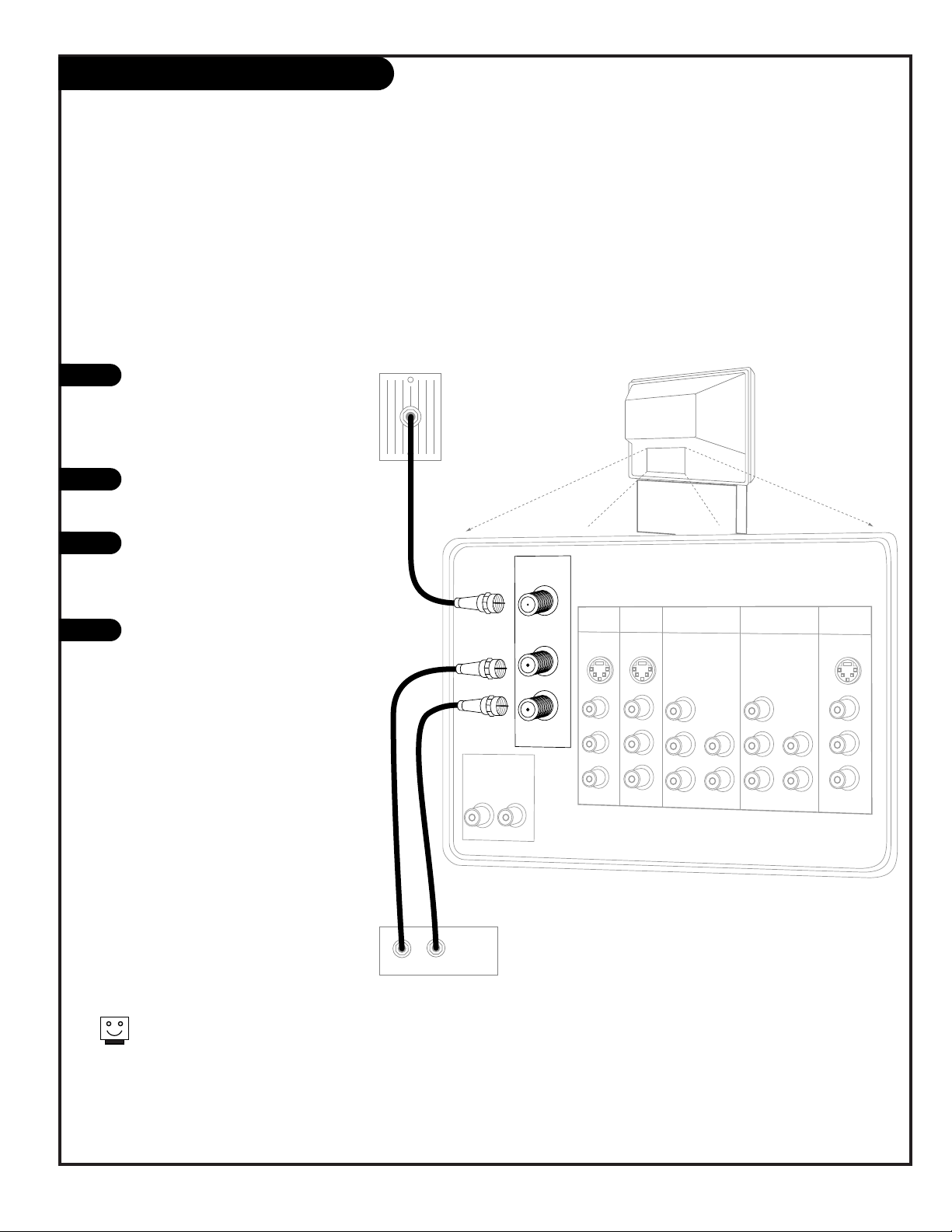
Hook Up Direct Cable TV or Antenna
Connect an off-air antenna
300 TO 75 OHM
ADAPTER
1
2
3
Locate the Antenna/Cable 1 jack on
the back of your Entertainment
Machine.
Connect the cable that runs from
the wall directly to this jack.
Turn to page 15 to continue setting
up your Entertainment Machine.
If you receive your RF signal through an
antenna that is several years old and connects with two small prongs, you will need
to purchase a 300 to 75 Ohm adapter. It
should be available from your local
electronics dealer.
Zenith recommends using a 75 Ohm cable
for your antenna connections in order to
prevent interference.
OR
Page 9
206-3594
PAGE 9
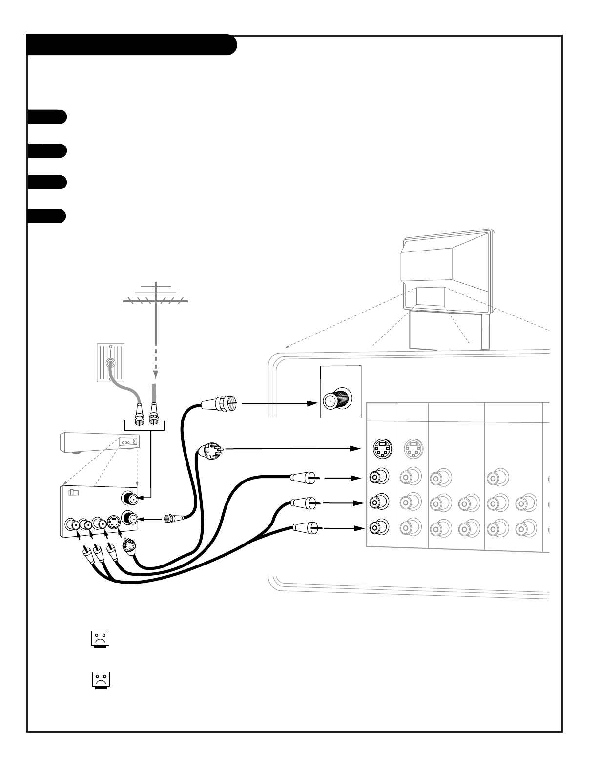
Hook Up Cable Box
1
2
3
4
Locate the Antenna/Cable 1 jack on
the back of your TV. Connect the
cable that runs from the wall directly to the jack. Now find the To Cable
Box jack.
Connect the cable from this jack to
the Input jack on the back of your
cable box.
Locate the Output jack on the back
of your cable box. Connect this to
the Antenna/Cable 2 jack on the
back of your TV.
To view the premium stations, set
the channel number on your cable
box to HBO, CINEMAX, SHOWTIME,
etc. Then press the Source button on
your remote and select the other
Cable source (Ant 2).
To view the non-premium channels
press the Source button and select
Ant 1. Then run Scan to check for all
available channels and store them in
memory.
Turn to page 15 to continue setting
up your Entertainment Machine.
Some cable services require the use of a cable box to decode premium channels and
pay-per-view. Using the “To Cable Box” to Decoder option, and programming your
remote, you can connect your cable box so that you only need your MBR remote to
control all the channels. By connecting cable directly to your Entertainment Machine,
then running it out to the cable box and back, you make the cable box another source
to choose from in the Source selection on your remote.
To receive premium channels, run
Auto Program on the second source
that is set to receive channels.
Cable TV
Wall Jack
Rf Coaxial Wire
(75ohm)
Cable Box
In
Out
VARIABLE
AUDIO OUT
R
L
ANTENNA/
CABLE 1
ANTENNA/
CABLE 2
TO CABLE
BOX
INPUT 1 INPUT 2
S-VIDEO
S-VIDEO
MONO/LRMONO/L
R
VIDEO
VIDEO
AUDIO
AUDIO
INPUT 3
INPUT 4
Y/VIDEO
P
B
PR
R
MONO/L
AUDIO
Y/VIDEO
P
B
PR
R
MONO/L
AUDIO
MONITOR
OUT
S-VIDEO
L
R
VIDEO
AUDIO
Page 10
PAGE 10
206-3594
Hook Up VCR
Connect your off-air antenna and VCR to your Entertainment Machine
VARIABLE
AUDIO OUT
R
L
ANTENNA/
CABLE 1
ANTENNA/
CABLE 2
TO CABLE
BOX
INPUT 1 INPUT 2
S-VIDEO
S-VIDEO
MONO/LRMONO/L
R
VIDEO
VIDEO
AUDIO
AUDIO
INPUT 3
INPUT 4
Y/VIDEO
P
B
PR
R
MONO/L
AUDIO
Y/VIDEO
P
B
PR
R
MONO/L
AUDIO
In
Out
Audio
Video
3 4
VCR
Back AV panel
A/V cables
not included
with TV
Cable TV
wall jack
Round wire
(75ohm)
RF coaxial wire
(75ohm)
Antenna
S-Video
OR
Or
Or
1
2
3
4
Locate the RF or VHF/UHF/CATV In jack on the back of your VCR. Connect the cable line coming
from your wall directly to this jack.
Locate the Antenna/Cable 1 jack on the back of your Entertainment Machine. Connect the cable
coming from the RF or VHF/UHF/CATV Out jack on the back of your VCR directly to this jack.
Find the composite video and audio jacks on the back of your VCR, and connect them following the instructions provided with your equipment.
You may connect either the composite video or the S-video cables to Inputs 1 or 2. (Do not
connect BOTH the composite and the S-Video cables to an input set of jacks. In the event
that you connect both composite and S-Video cables, only the S-video will work.)
Turn to page 15 to continue setting up your Entertainment Machine.
If you want to receive your signals on Channel 3 or 4, locate the Out
to TV jack on your VCR. Connect a cable from the Out to TV jack to the
Antenna/Cable 1 jack on the back of your Entertainment Machine.
For several pieces of equipment, edit the names under Source ID so
you don’t forget which is which. See page 31.
Note: Connect to either Input 1 or 2.
Page 11

PAGE 11
206-3594
Hook Up Cable Box with VCR
1
2
3
4
VARIABLE
AUDIO OUT
R
In
Out
Audio
Video
3 4
VCR
Back AV Panel
A/V cables
not included
with TV
Cable TV
Wall Jack
Round Wire
(75ohm)
S-Video
Or
Cable Box
In
Out
L
ANTENNA/
CABLE 1
ANTENNA/
CABLE 2
TO CABLE
BOX
INPUT 1 INPUT 2
S-VIDEO
S-VIDEO
MONO/LRMONO/L
R
VIDEO
VIDEO
AUDIO
AUDIO
INPUT 3
INPUT 4
Y/VIDEO
P
B
PR
R
MONO/L
AUDIO
Y/VIDEO
P
B
PR
R
MONO/L
AUDIO
Locate the RF or VHF/UHF/CATV In jack on the back of your VCR. Connect the cable line coming from your wall
directly to this jack.
Locate the Antenna/Cable 1 jack on the back of your TV. Connect the cable that runs from the RF or
VHF/UHF/CATV Out jack on the back of your VCR directly to this jack.
Now find the To Cable Box jack on your Entertainment Machine. Connect a cable from this jack to the Input
jack on the back of your cable box.
Locate the Output jack on the back of your cable box. Connect this to the Antenna/Cable 2 jack on the back of
your TV.
To view the premium stations, set the channel number on your cable box to HBO, CINEMAX, SHOWTIME, etc.
Then press the Source button on your remote and select the other Cable source (Ant 2).
To view the non-premium channels, press the Source button and select Ant 1. Then run Scan to check for all
available channels and store them in memory.
Find the composite video and audio jacks on the back of your VCR, and connect them as shown below to either
Input 1 or 2, following the instructions provided with your equipment.
You may connect either the composite video or the S-video cables to your Entertainment
Machine to inputs 1 or 2. (Do not connect BOTH the composite and the S- Video cables.
In the event that you connect both composite and S-Video cables, only S-video will work.)
Turn to page 15 to continue setting up your Entertainment Machine.
5
6
7
8
Note: Connect to either Input 1 or 2.
Page 12

VARIABLE
AUDIO OUT
R
L
ANTENNA/
CABLE 1
ANTENNA/
CABLE 2
TO CABLE
BOX
INPUT 1
S-VIDEO
S-VIDEO
MONO/LRMONO/L
R
VIDEO
VIDEO
AUDIO
AUDIO
INPUT 3
INPUT 4
R
MONO/L
AUDIO
Y/VIDEO
P
B
PR
R
MONO/L
AUDIO
MONITOR
OUT
S-VIDEO
L
R
VIDEO
AUDIO
INPUT 2
VARIABLE
AUDIO OUT
R
L
ANTENNA/
CABLE 1
ANTENNA/
CABLE 2
TO CABLE
BOX
INPUT 1 INPUT 2
S-VIDEO
S-VIDEO
MONO/LRMONO/L
R
VIDEO
VIDEO
AUDIO
AUDIO
INPUT 3
INPUT 4
Y/VIDEO
P
B
PR
R
MONO/L
AUDIO
Y/VIDEO
P
B
PR
R
MONO/L
AUDIO
MONITOR
OUT
S-VIDEO
L
R
VIDEO
AUDIO
Audio
L R
S-Video
A/V cables
not included
with TV
If you have a DVD Player
with Component Video, use
these jacks marked Y, Pb, and Pr.
DVD Player
Back AV Panel
R
Audio
L R
A/V cables
not included
with TV
DVD Player
Back A/V Panel
Component Video
Out
YPbPr
Y/VIDEO
P
B
PR
PAGE 12
206-3594
1
2
3
Hook Up DVD Player and HD Set Top Box
For several pieces of equipment, edit the names under Source
ID so you don’t forget which is which. See page 31.
Some high-end DVD players and High-Definition Set Top Boxes use a picture reproduction system called “component video.” If your DVD player or
High-Definition Set Top Box has component output, use these connections. Then go to the section on Component Input on page 29 to select
the color system for your DVD or High-Definition Set Top Box.
Find the audio and composite or S-Video jacks on the back of your DVD
Player and connect them as shown below, following the instructions provided with your equipment.
You may connect either the composite video or the S-Video cables to your
Entertainment Machine Inputs 1 or 2. (Do not connect both the composite and the S-Video. In the event
that you connect both composite
and the S-video cable, only the
S-Video will work.)
Use the SOURCE button on
your remote to choose the DVD
or Set Top box source.
Note: Connect to either Input 1 or 2.
Note: Connect to either Input 3 or 4.
Page 13
PAGE 13
206-3711
Hook Up External Stereo
1
2
3
4
Locate the Variable Out jacks on the back of your Entertainment
Machine and the Input jacks on the back of your stereo's amplifier.
Use appropriate audio cables to connect these jacks, making sure that
the right and left channels are matched correctly; right to right, left
to left.
Set up your speakers through your stereo, according to those directions.
Turn off the TV’s internal speakers using that option on the Audio
Menu. See page 39.
Send the sound from your Entertainment Machine to an
external audio amplifier system; use it to hear the audio
External stereo amplifier
Audio cables
not included
with TV
VARIABLE
AUDIO OUT
R
L
ANTENNA/
CABLE 1
ANTENNA/
CABLE 2
TO CABLE
BOX
INPUT 1 INPUT 2
S-VIDEO
S-VIDEO
MONO/LRMONO/L
R
VIDEO
VIDEO
AUDIO
AUDIO
INPUT 3
INPUT 4
Y/VIDEO
P
B
PR
R
MONO/L
AUDIO
Y/VIDEO
P
B
PR
R
MONO/L
AUDIO
MONITOR
OUT
S-VIDEO
L
R
VIDEO
AUDIO
To prevent damage to the speaker and avoid distorted sound, set the
volume control of the audio amplifier to a quiet or low setting and
adjust the sound on the TV, using the remote control or the front panel
volume controls.
Page 14

VARIABLE
AUDIO OUT
R
L
ANTENNA/
CABLE 1
ANTENNA/
CABLE 2
TO CABLE
BOX
INPUT 1 INPUT 2
S-VIDEO
S-VIDEO
MONO/LRMONO/L
R
VIDEO
VIDEO
AUDIO
AUDIO
INPUT 3
INPUT 4
Y/VIDEO
P
B
PR
R
MONO/L
AUDIO
Y/VIDEO
P
B
PR
R
MONO/L
AUDIO
MONITOR
OUT
S-VIDEO
L
R
VIDEO
AUDIO
Audio
Video
VCR
Back AV panel
A/V cables
not included
with TV
S-Video
Or
Or
PAGE 14
206-3806
Hook Up Monitor Out
1
2
Locate the Monitor Out jacks on the back of your Entertainment Machine and
the Input jacks on the back of your VCR.
Connect the Input jacks from your VCR to the Monitor Out jacks on the back of
your Entertainment Machine as shown in the diagram.
You may connect either the composite video or the S-video cables to your
Entertainment Machine. (Do not connect BOTH the composite and the S- Video
cables. In the event that you connect both composite and the S-Video cables,
only the S-video will work.)
Program your VCR to record from the Video (or S-Video) input. See your VCR
operating manual for details.
The Monitor Out jacks on your Entertainment Machine allow you to record to a second VCR!
NOTE: S-VIDEO out only works when recording an S-VIDEO input.
(You cannot use S-VIDEO out to record the ANT 1/2 input.)
Page 15

Use pages 7-14 to hook up your Entertainment Machine.
Plug your Entertainment Machine into a standard
120V 60Hz power outlet.
Remove the back of the remote and put in two “AA” batteries. Make sure batteries are properly installed (check the
+/– signs).
Turn on your Entertainment Machine by pressing the POWER
button on your remote.
Press the MENU button on your remote.
Choose Signal using the DOWN arrow button.
Activate the Signal Menu option by pressing the RIGHT
arrow button on your remote.
Choose the signal source for your Entertainment Machine. If
your signal comes from an outdoor antenna, leave set at
ANTENNA. If your signal comes from a cable TV service,
select CATV 1 by pressing the DOWN arrow button. Press
“select” to set (confirm) your choice, then press the MENU
button to return to the Setup Menu.
Continue to the next page to scan for available channels.
Trilingual Menus
Signal Antenna
Scan CATV 1
Channel Add/Del CATV 2
Channel Review
Clock Set
EZ Focus
Picture Formats
Trilingual Menus
Signal Antenna
Auto Program CATV 1
Channel Add/Del CATV 2
Channel Review
Clock Set
EZ Focus
Picture Formats
Trilingual Menus
Signal Antenna
Scan CATV 1
Channel Add/Del CATV 2
Channel Review
Clock Set
EZ Focus
Picture Formats
VideoSetup Special Audio Theater
QuitTo ExitTo Menu BarMenu
QuitTo ExitTo Menu BarMenu
QuitTo ExitTo Menu BarMenu
SEL
Setup
SEL
Press select to set
Setup
SEL
Press select to set
PAGE 15
206-3806
Signal Source Selection
Back of
Remote
1
2
3
4
5
7
8
6
mute
vol
ch
flshbk
pause
rew
f f
play
record
stop
skip
CC
quit
pip
menu
multi
sleep
c skip
pip ch
fav ch
theatr
Menu
Quit
Select
Up Arrow
Down Arrow
Left Arrow
Right Arrow
Page 16

PAGE 16
206-3806
Scan (Channel Search)
Press the MENU button on your remote to display the
Setup Menu. (If the Menu is already on-screen, skip
this step.)
Choose Scan mode using the DOWN arrow button on
your remote.
Press the RIGHT arrow button to choose Scan.
Press the SELECT button on your remote to begin
Scan (the channel search).
If certain CATV channels are not received clearly in CATV1
mode, set signal to CATV2 mode.
Continued from previous page.
Trilingual Menus
Signal
Scan Begin
Channel Add/Del
Channel Review
Clock Set
EZ Focus
Picture Formats
Installing
Channel 110
50% Complete
QuitTo ExitTo Menu BarMenu
QuitTo ExitTo Menu BarMenu
QuitTo ExitTo Menu BarMenu
Trilingual Menus
Signal
Scan Begin
Channel Add/Del
Channel Review
Clock Set
EZ Focus
Picture Formats
Trilingual Menus
Signal
Scan
Channel Add/Del
Channel Review
Clock Set
EZ Focus
Picture Formats
VIDEOSETUP AUDIO THEATER
SEL
SPECIAL
SEL
Press select to set
SETUP
VIDEOSETUP AUDIO THEATER
SEL
SPECIAL
1
2
3
4
1 2 3
4 5 6
7 8 9
0
mute
vol
ch
flshbk
pause
rew
f f
play
record
stop
skip
CC
quit
pip
tv
vcr
power
dvd
hd/stb
cable
menu
multi
tv
vcr
cable
hd/stb
light
dvd
sleep
mode
aspect
c skip
pip ch
display
fav ch
theatr
source
Menu
Quit
Select
Up Arrow
Down Arrow
Left Arrow
Right Arrow
Page 17

206-3806
PAGE 17
1 2 3
4 5 6
7 8 9
0
mute
vol
ch
flshbk
pause
rew
f f
play
record
stop
skip
CC
quit
pip
tv
vcr
power
dvd
hd/stb
cable
menu
multi
tv
vcr
cable
hd/stb
light
dvd
sleep
mode
aspect
c skip
pip ch
display
fav ch
theatr
source
remote control part number
MBR5045
924-10114
Remote Operating Mode
Indicator Lights
Light indicates the active mode
when a key is pressed.
Mode selection keys: TV,
VCR, CABLE, DVD, HD/STB
Switches remote operating mode to
control other devices.
Note: After pressing a Mode switch
key, wait 2 - 3 seconds before
pressing any other key.
ASPECT
Selects different picture
proportion formats.
POWER
Turns TV On and Off.
CH - CHANNEL (+/ -)
Tunes to next higher/lower
available channel.
MENU
Displays on-screen menus.
UP/DOWN/LEFT/RIGHT/SELECT
(Menu Operation Directional
Arrows and Select key)
Up/Down arrows choose, and
Left/Right arrows adjust menu
options. Press the bulls eye Select
button in the center of the directional arrows to confirm selection.
PIP CH
Channel tuning switch in Split
Screen mode. See Split Screen
section.
FLSHBK (FLASHBACK)
Returns to the previously
tuned channel.
SKIP I<<
Left chapter scan for DVD.
SKIP >>I
Right chapter scan for DVD.
NUMBER KEYPAD 0 - 9
Selects channels directly and
enters numerical values.
- (Digital Mode Dash)
Use as the dash when selecting
digital channel numbers.
VOL - (VOLUME) (+/-)
+ Increases the sound level.
- Decreases the sound level.
CC
Turns On/Off Closed
caption/text options.
VCR Function Keys
RECORD, STOP, PAUSE, REW
(Rewind), PLAY, FF (Fast
Forward) Still operate your VCR,
while remote is in TV operating
mode.
TV Mode Remote Key Functions
SOURCE
Selects available TV sources.
LIGHT
Lights keys for five seconds.
SLEEP (TIMER)
Sets a preset time for the TV
to turn itself off.
DISPLAY
Shows current on-screen settings.
QUIT
Leaves programming menus and
clears screen of displays.
MUTE
Press once for Soft Mute,
press again for full Mute.
THEATER
Direct access to theater modes.
FAVORITE CHANNEL
Select among 6 different channel
classifications.
*Note: Digital broadcasters can transmit multiple programs on a single channel. These
programs are distinguished by a unique “sub-channel” number, separated when entering
digits by the “—” button on your remote.
PIP
Turns PIP on and off.
C SKIP
Channel Skip. Tunes to last channel viewed. Tunes back to original
channel after 30, 60, 90, 120,
150, or 180 seconds.
MULTI
Turns “POP-3” feature on and off.
Page 18

PAGE 18
206-3711
On-Screen Display
STEREO
ST / SAP TV - PG DLSV
ANT 1 110
ABC
10 : 00 AM
PIP ANT 1 14
SKIP ( C. S. )
OFF 10:05 AM
SLEEP 0:01
STEREO
ST / SAP TV - PG DLSV
ANT 1 110
ABC
10 : 00 AM
May 14 2002
C. SKIP ( C. S. )
OFF 10:05 AM
SLEEP 0:01
TV
Normal
TV
Normal
AUDIO SELECTED
Displays signal’s audio setting.
CHANNEL SKIP
Shows that Channel Skip is
active.
SECURITY TIMER
Displays time that TV is set to
turn off.
SLEEP TIMER SET
Displays time left on Sleep Timer
before TV shut off.
MAIN PICTURE SOURCE
Displays Main Picture Source
(Active source highlighted).
MONTH/DATE/YEAR
Shows current month, date,
and year.
RATING BROADCAST
Displays the rating for the pro-
gram currently being broadcast.
CHANNEL LABEL
Displays channel label you
have chosen.
AUDIO BROADCAST
Displays signal’s audio broadcast.
TIME
Displays clock setting.
This page explains your on-screen display, press
DISPLAY on remote to show on screen
PICTURE FORMAT
Shows current Theater mode
setting.
Page 19

Mini glossary
MENU On-screen displays used to set up and operate TV features.
SEL (Select) Selection key used to confirm changes on the menus.
UP/DOWN Menu UP or DOWN directional arrows used to highlight menu
options.
LEFT/RIGHT Menu LEFT or RIGHT directional arrows used to “adjust”
some menu settings.
QUIT Exits menus and removes on-screen displays.
206-3711
Use the remote to access the on-screen menus
Press MENU on the remote control. Use the Right or Left directional arrow to highlight (change the text color to gold) the
name of one of the five main menus on your screen like the
SETUP menu.
Use the Up or Down directional arrow to highlight an option
like Contrast. You can highlight other menu options like Color
Temperature by pressing the UP or DOWN directional arrow
repeatedly.
Once the option is selected, in this case CONTRAST, use the
RIGHT or LEFT directional arrow to adjust the setting; the larger the number the more contrast, the lower the number, the
less contrast in the picture.
You can adjust the other menu options using the above procedure or if you are done changing the menu option settings,
press QUIT to remove the menus from the TV screen.
On-Screen Menu Operation
1
2
3
4
Additional instructions are usually included on the top and bottom of
the menu indicating which remote keys to use to move to the right,
move to the left, return to the original menu, and to exit the menu
etc.
pause
rew
f f
play
record
stop
skip
CC
quit
menu
sleep
fav ch
theatr
1/4
2
3
When chosen, menu title (shown here in gray for clarity)
and highlighted menu option fields change to a gold color
PAGE 19
4
Press the thumbstick center
bulls-eye “SELECT” (Shown as
SEL on the upper-left side of
menus) when required to set
your selection.
QuitTo ExitTo Menu BarMenu
QuitTo ExitTo Menu BarMenu
Contrast 75 %
Brightness 50%
Color 50%
Tint
Sharpness 50%
Reset
Advanced
Settings
Advanced Settings
Light Sentry
Auto Flesh
Weak Signal
Color Temperature
Cool
Medium
Warm
SEL
Press select to set
VIDEO
VIDEOSETUP AUDIO THEATER
SEL
SPECIAL
“To Menu Bar” indicates that if you press MENU,
TV returns to main menu selection options
“Sel” indicates that Select is the center bulls-eye on
remote. Select is used to activate menu selections.
Page 20

PAGE 20
206-3806
Sources/Equipment Hookup Options
1
Choose the picture and sound source you want to see and hear
On the remote, press SOURCE repeatedly to choose from
the available viewing sources connected to the TV.
Antenna 1 - 2: Antenna/Cable inputs on TV back near
Jackpack, Over-the-Air Antenna or Cable service signal
source.
Input 1: on TV Rear Jackpack,
Set of Composite Audio/Video Input jacks.
Input 2: on TV Rear Jackpack,
Set of Composite Audio/Video Input jacks.
Input 3: on TV Rear Jackpack,
Set of Component/Composite Audio/Video Input jacks.
Input 4: on TV Rear Jackpack,
Set of Component/Composite Audio/Video Input jacks.
Input 5: on TV Front Jackpack,
Set of Composite Audio/Video Input jacks.
VARIABLE
AUDIO OUT
R
L
ANTENNA/
CABLE 1
ANTENNA/
CABLE 2
TO CABLE
BOX
INPUT 1 INPUT 2
S-VIDEO
S-VIDEO
MONO/LRMONO/L
R
VIDEO
VIDEO
AUDIO
AUDIO
INPUT 3
INPUT 4
Y/VIDEO
P
B
PR
R
MONO/L
AUDIO
Y/VIDEO
P
B
PR
R
MONO/L
AUDIO
MONITOR
OUT
S-VIDEO
L
R
VIDEO
AUDIO
Input 5
S-Video Video L/Mono R
AUDIO/VIDEO OUT
VIDEO
R -AUDIO-L
AUDIO/VIDEO OUT
VIDEO
R -AUDIO-L
AUDIO IN
R -AUDIO-L
AUDIO/VIDEO OUT
VIDEO
R -AUDIO-L
AUDIO IN
R -AUDIO-L
Camcorder
Component
Video
VCR
S-Video VCR
DVD Player
Other
Typical Viewing Sources
The source equipment you intend to view should be turned on.
Inputs 3 and 4 (Y-VIDEO) can also be used for standard video input.
Connection Notes
• Be sure to insert connection cord plugs securely when
connecting to front panel jacks, or the played back
image may be abnormal.
• For S-Video, use the S-Video cable in place of the
standard video cable.
• S-Video Monitor Out only works when an S-Video
device is connected to either Inputs 1, 2, or 5.
• For monaural VCR sound output, insert the VCR audio
out cable into the Left audio in jack on the TV.
Page 21

PAGE 21
206-3806
Front Control Panel/Connection Jacks
To access the menus, press the MENU button on the panel. Also use MENU as the
Select key when required.
Use the VOLUME Left/Right buttons as
the LEFT/RIGHT arrow buttons on your
remote.
Use the CHANNEL Up/Down buttons as
the UP/DOWN arrow buttons on your
remote.
Push the QUIT button to return to normal
TV viewing.
Press the SOURCE button to cycle through
all sources.
Refer to the menu pages for using the
on-screen menus.
The CHANNEL and VOLUME buttons work
just as they do on your remote control.
Auto Demo is activated by pressing the
POWER button on the front panel and
holding down on the button. To turn Auto
Demo off, press the POWER button once.
There are four jacks on the front panel of your
Entertainment Machine that make connecting
Audio/Video equipment like video games and
camcorders very simple.
The jacks are identical to those found on the
back of your Entertainment Machine. This means
that any equipment that connects to those
types of jacks on the rear jack connections
panel, can also be connected to the front panel.
To select the front jacks as the signal source,
use the SOURCE button on your remote. To
change the name of the front video source,
Input 5, see page 31.
1
2
3
4
5
Use the front control panel to operate the TV’s basic features and the front
Audio/Video source input panel jacks to make temporary connections
S-Video Video L/Mono R
select
5
2
3
4
1
Page 22

PAGE 22
206-3806
On-Screen Menus Overview
Descriptions of the on-screen menus
Using MENU, the Up/Down/Left/Right arrows, and the thumbstick bulls eye (Select),
the user can access the following menus.
SETUP MENU Adjust the basic characteristics of your Entertainment Machine.
Trilingual Menus 24 Pick the language (English, French, Spanish) that you want the on-screen menus to appear in.
Signal 15 Specify the type of incoming Signal Source (Antenna or Cable) for the Antenna/Cable 1 jack.
Scan 16 Automatically find and store active channels to tune to using Channel Up/Down.
Channel Add/Del 25 Manually pick and choose which active channels will appear when using Channel Up/Down.
Channel Review 26 Review the labels and Parental Controls you have placed on your channels.
Clock Set 27 Set the Clock on your Entertainment Machine.
EZ Focus 28 Use to have the TV automatically adjust the color convergence.
Picture Formats 29 Choose the picture aspect style for your DVD player or High Definition Set-top Box source.
SPECIAL MENU Go beyond basics and customize your Entertainment Machine’s features.
Channel Labels 30 Label your channels with their network names (ABC, CBS, HBO, etc.).
Source ID 31 Customize the names of your sources by either selecting a preset label or making your own.
Favorite Channels 32 Choose your Favorite Channels according to their category: Movies, Sports, News, Sitcoms,
Music, or Custom.
Parental Control 33 Allows parents to block program content with the use of a password.
Security Timer 35 Program up to four separate times for your Entertainment Machine to turn itself on or off, or to
turn itself off after a certain amount of time.
Captions 36 Choose a captioning or text option for your TV.
Background 37 Change the background of the on-screen menus to solid or shaded.
Page 23

PAGE 23
206-3806
On-Screen Menus/Displays Overview
Menu Name Page Menu Description
VIDEO MENU 3 8 Adjust your picture for any viewing situation. Your options are: Contrast, Brightness, Color, Tint,
Sharpness, Reset and Advanced Settings: Light Sentry, Auto Flesh, Weak Signal,
Color Temperature: Cool, Medium, Warm.
AUDIO MENU 3 9 Customize the sound to suit your room and your taste. Your options are: Bass, Treble, Balance,
Reset and Advanced Settings: Stereo, Mono, Second Audio Program, Internal Speakers,
Auto Noise Cancel, Loudness, and SoundRite.
THEATER MENU 4 0 Select the right audio and video automatic configuration setup that optimize your TV’s
performance for TV, Movies, Music, Sports, or Reset.
Select Surround sound options.
Displays
POP-3 4 1 Show a continuous 3-channel presentation in numerical series on your Entertainment Machine.
PIP SCREEN 4 3 Display Picture-in-Picture to show two different channels at the same time on your
Entertainment Machine.
Page 24

206-3806
PAGE 24
Trilingual Menus
1
2
3
4
5
Trilingual Menus English
Signal Francais
Scan Español
Channel Add/Del
Channel Review
Clock Set
EZ Focus
Picture Formats
Trilingual Menus English
Signal Francais
Scan Español
Channel Add/Del
Channel Review
Clock Set
EZ Focus
Picture Formats
Trilingual Menus English
Signal Francais
Scan Español
Channel Add/Del
Channel Review
Clock Set
EZ Focus
Picture Formats
QuitTo ExitTo Menu BarMenu
QuitTo ExitTo Menu BarMenu
QuitTo ExitTo Menu BarMenu
VIDEOSETUP AUDIO THEATER
SEL
SPECIAL
SEL
Press select to set
SETUP
SEL
Press select to set
SETUP
Choose the language you want the on-screen
menus to appear in; English, French, or Spanish
Press MENU to access the Setup menu.
Use the DOWN arrow to choose Trilingual.
Press the RIGHT arrow button to activate the
Language menu option.
Use the UP/DOWN arrow button to choose your
language preference for the on-screen menus,
press Select to set and confirm your choice.
Press QUIT to exit and save your choice.
1 2 3
4 5 6
7 8 9
0
mute
vol
ch
flshbk
pause
rew
f f
play
record
stop
skip
CC
quit
pip
tv
vcr
power
dvd
hd/stb
cable
menu
multi
tv
vcr
cable
hd/stb
light
dvd
sleep
mode
aspect
c skip
pip ch
display
fav ch
theatr
source
Menu
Quit
Select
Up Arrow
Down Arrow
Left Arrow
Right Arrow
Page 25

PAGE 25
206-3806
Channel Add/Del (Delete)
1
2
3
4
5
Customize your channel selection list: Add Channels not
found by Scan (Channel Search), Delete channels you don’t
watch. Channels will appear when using Channel Up/Down
Trilingual Menus
Signal Channel 03
Scan Add
Channel Add/Del Erase
Channel Review Next Channel
Clock Set Ch Ch
EZ Focus Or # Keys
Picture Formats
Trilingual Menus
Signal
Scan Channel 03
Channel Add/Del Add
Channel Review Erase
Clock Set
EZ Focus
Picture Formats
QuitTo ExitTo Menu BarMenu
QuitTo ExitTo Menu BarMenu
QuitTo ExitTo Menu BarMenu
Trilingual Menus
Signal Channel 03
Scan Add
Channel Add/Del Erase
Channel Review Next Channel
Clock Set Ch Ch
EZ Focus Or # Keys
Picture Formats
VIDEOSETUP AUDIO THEATER
SEL
SPECIAL
SEL
Press select to set
SETUP
SEL
Press select to set
SETUP
Press the MENU button on your remote to access the
Setup menu.
Use the UP/DOWN arrow to choose Channel Add/Del.
Press the RIGHT arrow button to activate the Channel
Add/Del menu option.
Use the UP/DOWN arrow button to choose the Add or
Delete option for the currently chosen channel, press
Select to set and confirm your choice.
Press QUIT to exit and save your choice or use the
Channel UP/DOWN buttons/numbers to choose another
channel to Add or Erase.
1 2 3
4 5 6
7 8 9
0
mute
vol
ch
flshbk
pause
rew
f f
play
record
stop
skip
CC
quit
pip
tv
vcr
power
dvd
hd/stb
cable
menu
multi
tv
vcr
cable
hd/stb
light
dvd
sleep
mode
aspect
c skip
pip ch
display
fav ch
theatr
source
Menu
Quit
Select
Up Arrow
Down Arrow
Left Arrow
Right Arrow
Page 26

206-3806
PAGE 26
Channel Review
Press MENU to access the Setup menu.
Use the UP/DOWN arrow to choose the Channel
Review option.
Use the RIGHT arrow button to activate the Channel
Review menu option.
Use the UP/DOWN arrow button to cycle through
your channel list and review the settings. (Each
press of Up/Down arrows will display the next eight
channels.)
Press QUIT to exit.
Review channel settings on your Entertainment Machine
QuitTo ExitTo Menu BarMenu
CHANNEL REVIEW Ant 1
Ch Id Scan Lock
1 * * * * ON ON
2 * * * * - - - 3 * * * * - - - 4 * * * * - - - 5 * * * * - - - 6 * * * * - - - 7 * * * * - - - 8 * * * * - - - -
Trilingual Menus
Signal
Scan
Channel Add/Del
Channel Review
Clock Set
EZ Focus
Picture Formats
QuitTo ExitTo Menu BarMenu
VIDEOSETUP AUDIO THEATER
SEL
SPECIAL
VIDEOSETUP AUDIO THEATER
SEL
SPECIAL
1
2
3
4
5
1 2 3
4 5 6
7 8 9
0
mute
vol
ch
flshbk
pause
rew
f f
play
record
stop
skip
CC
quit
pip
tv
vcr
power
dvd
hd/stb
cable
menu
multi
tv
vcr
cable
hd/stb
light
dvd
sleep
mode
aspect
c skip
pip ch
display
fav ch
theatr
source
Menu
Quit
Select
Up Arrow
Down Arrow
Left Arrow
Right Arrow
Page 27

PAGE 27
206-3806
Clock Set
1
2
3
4
5
12 : 00 Am
May 02 2002
TO SET TIME
Trilingual Menus
Signal
Scan
Channel Add/Del
Channel Review
Clock Set
EZ Focus
Picture Formats
QuitTo ExitTo Menu BarMenu
QuitTo ExitTo Menu BarMenu
SEL
Trilingual Menus
Signal
Scan
Channel Add/Del
Channel Review
Clock Set
EZ Focus
Picture Formats
VIDEOSETUP AUDIO THEATER
SEL
SPECIAL
SETUP
Press the MENU button on your remote to
access the Setup menu.
Use the UP/DOWN arrow to choose Clock Set.
Use the RIGHT arrow button to set the clock on
your Entertainment Machine.
Use the RIGHT arrow button to choose first the
time option and use the UP/DOWN arrow buttons to adjust time options. Press the RIGHT
arrow button and then use the UP/DOWN arrow
buttons to adjust month/date/year options.
Press QUIT to save and exit.
Set the clock on your Entertainment Machine
1 2 3
4 5 6
7 8 9
0
mute
vol
ch
flshbk
pause
rew
f f
play
record
stop
skip
CC
quit
pip
tv
vcr
power
dvd
hd/stb
cable
menu
multi
tv
vcr
cable
hd/stb
light
dvd
sleep
mode
aspect
c skip
pip ch
display
fav ch
theatr
source
Menu
Quit
Select
Up Arrow
Down Arrow
Left Arrow
Right Arrow
Page 28

PAGE 28
206-3711
EZ Focus (Color Convergence)
1
2
3
4
Trilingual Menus
Signal
Scan
Channel Add/Del
Channel Review
Clock Set
EZ Focus
Picture Formats
QuitTo ExitTo Menu BarMenu
VIDEOSETUP AUDIO THEATER
SEL
SPECIAL
Press the MENU button on your remote to access the Setup menu.
Use the UP/DOWN arrow to choose EZ Focus.
Press the RIGHT arrow button to go to the EZ Focus convergence
menu.
Press SELECT on the thumbstick to go to EZ FOCUS menu.
Press MENU repeatedly to choose the color to adjust: Red or Blue.
There are 9 color convergence points. Align the Middle Center
point first. Press 5 on the number keypad to select the Middle
Center convergence point. Use the thumbstick, up/down/left/right
arrows to move the color bar so that it lines up exactly over
Green. (Green is stationary and does not move.)
Adjust the other convergence points by selecting them with the
number keypad, press the numbers indicated to select:
1=Upper Left 2=Upper Center 3=Upper Right
4=Middle Left 5=Middle Center 6=Middle Right
7=Bottom Left 8=Bottom Center 9=Bottom Right
Press MENU to change the color. Align the selected color convergence points as instructed above. When convergence is correct,
the convergence point color is white.
Press MULTI or QUIT to remove color convergence menu and store
your color convergence changes. (To return to the previous color
convergence alignment, press POWER or PIP. No convergence
changes will be stored and the TV will revert back to the previous
convergence setup when it is turned on again.)
Adjust red, blue, and green color convergence for optimum
picture appearance
Red, Blue, over Green.
Correct Convergence=White
5
Page 29

PAGE 29
206-3711
Picture Formats
1
2
3
4
5
Picture Formats Ant 1 26
Aspect Style Aspect 1
Aspect 2
Aspect 3
Aspect 4
TRU-HD
V. Position +4
Comp. Color Type HDTV
SDTV/DVD
Video Display 1080i
540p
Trilingual Menus
Signal
Scan
Channel Add/Del
Channel Review
Clock Set
EZ Focus
Picture Formats
QuitTo ExitTo Menu BarMenu
QuitTo ExitTo Menu BarMenu
SEL
Press select to set
VIDEOSETUP AUDIO THEATER
SEL
SPECIAL
SETUP
Choose the source you want to set the picture format for.
Press the MENU button on your remote to access the Setup
menu.
Use the UP/DOWN arrow to choose Picture Formats.
Use the RIGHT arrow button to access the Picture formats
Menu.
Choose and set the options based on your equipment’s signal
requirements for high-definition or standard NTSC sources.
Aspect Style Aspect 1, Aspect 2, Aspect 3,
Aspect 4, Aspect 5, TRU-HD
V. Position Image vertical position on screen
Comp. Color Type HDTV, SDTV/DVD
Video Display 1080i, 540p
Press SELECT to set and confirm your settings.
Press QUIT to save and exit.
Fine-tune High Definition and standard NTSC analog
signal source images
6
1 2 3
4 5 6
7 8 9
0
mute
vol
ch
flshbk
pause
rew
f f
play
record
stop
skip
CC
quit
pip
tv
vcr
power
dvd
hd/stb
cable
menu
multi
tv
vcr
cable
hd/stb
light
dvd
sleep
mode
aspect
c skip
pip ch
display
fav ch
theatr
source
Menu
Quit
Select
Up Arrow
Down Arrow
Left Arrow
Right Arrow
7
Note: 1080i signal source settings are fixed while other signal
source formats are adjustable. (1080i=1080i)
(TV converts 720p to 540p, 480p to 540p, 480i to 540p.)
Page 30

PAGE 30
206-3806
Tune to a channel you want to label.
Press MENU on your remote and then use the
RIGHT/LEFT arrow button to access the Special Menu.
Use the UP/DOWN arrow to choose Channel Labels.
Press the RIGHT arrow button to activate the Channel
Labels option.
At this point you have three options:
• Select a pre-set channel label by choosing Ch Labels.
• Customize a channel label by choosing Custom Ch.
• Delete a channel label entirely by choosing Reset.
Use the UP/DOWN arrows to choose an option.
If you chose Ch Labels, press the RIGHT arrow button
to access the preset channel label list and scroll
through this list using the UP/DOWN arrow buttons.
When you find the appropriate label for the channel,
press the SELECT button.
If you select Custom Channel, press the RIGHT arrow
button once and then use the UP/DOWN arrow buttons
to select individual letters and LEFT/RIGHT arrow buttons to choose placement of letters.
If you wish to delete a channel, choose Reset using
the UP/DOWN arrow buttons from Step 5, and then
press the SELECT button on your remote. You will be
asked “Are You Sure?” press SELECT again to delete.
Use CHANNEL UP/DOWN buttons or the NUMBER KEYPAD and choose another channel to label. Repeat steps
5-6-7 for all channels you wish to label.
Press QUIT to save and exit.
Channel Labels
X X X X (Custom)
Channel Labels
Source I D
Favorite Channels
Parental Control
Security Timer
Captions
Background
Channel Labels
Ch 03 X X X X
Ch Labels
Custom
Reset
QuitTo ExitTo Menu BarMenu
QuitTo ExitTo Menu BarMenu
Next Ch
Ch Ch
Or #Keys
To Change Letter
Channel Labels
Ch 03 X X X X
Ch Labels
Custom Ch.
Reset
QuitTo ExitTo Menu BarMenu
Next Ch
Ch Ch
Or #Keys
ABC
CBS
ESPN
HBO
NBC
SHOW
To Change Letter
Channel Labels
Ch 03 X X X X
Ch Labels
Custom
Reset
QuitTo ExitTo Menu BarMenu
QuitTo ExitTo Menu BarMenu
Next Ch
Ch Ch
Or #Keys
SEL
SEL
VIDEOSETUP AUDIO THEATER
SEL
SPECIAL
VIDEOSETUP AUDIO THEATER
SEL
SPECIAL
SPECIAL
SPECIAL
1
2
3
4
5c
Use the preset labels to name the channels or create your
own channel labels on your Entertainment Machine
5
5a
5b
6
7
Page 31

PAGE 31
206-3711
Source ID
1
2
3
4
5
IN 1 IN 2 IN 5
IN 3 IN 4
Source List
Custom
Reset
VCR 1
CD
DVD
TAPE
LD
AUX
Channel Labels
Source I D
Favorite Channels
Parental Control
Security Timer
Captions
Background
QuitTo ExitTo Menu BarMenu
QuitTo ExitTo Menu BarMenu
QuitTo ExitTo Menu BarMenu
SEL
Press select to set
SEL
Press select to set
VIDEOSETUP AUDIO THEATER
SEL
SPECIAL
SPECIAL
SPECIAL
Source I.D.
Source I.D.
IN 1 IN 2 IN 5
IN 3 IN 4
Source List
Custom
Reset
Press MENU and the RIGHT/LEFT arrow button to
access the Special Menu.
Use the UP/DOWN arrow to select Source ID.
Press the RIGHT arrow button to activate the Source
ID option.
Use the RIGHT arrow button to choose In 1, In 2,
In 3, In 4, or In 5 (for front video jacks).
Use the UP/DOWN arrow buttons to go to Source List
to choose a pre-set Source identification, go to
Custom to create your own label, or pick Reset to
clear all labels.
If you chose Source List, press the RIGHT arrow button
to access the list and then use the UP/DOWN arrow
buttons to pick an ID from the list. Press SELECT to
save your choice.
If you wish to customize your source ID, go to Custom
(from Step 5), then press the RIGHT arrow button.
Cycle through the character choices using the
UP/DOWN buttons and cycle through the character
slots using the RIGHT arrow button. Press QUIT to
save your choice and exit.
Note: Use * for blank spaces.
To delete a Source ID, select Reset (from Step 5), then
press the SELECT button. You will be asked “Are You
Sure?” Press SELECT again and then press QUIT to save
and exit.
Note: When you label Input 1, Input 2, etc. the TV
will automatically change to the source of the last
source labeled. To return to your original viewing
source, press the Source button on the remote
repeatedly until you see the picture you were originally watching.
Choose preset names or create your own titles for the available picture/sound input
sources on your Entertainment Machine
6
7
8
Page 32

PAGE 32
206-3711
Press MENU and then RIGHT/LEFT arrow button to
access the Special Menu.
Use the UP/DOWN arrow to choose Favorite Channels.
Press the RIGHT arrow button to activate Favorite
Channels option.
Use the RIGHT arrow button to choose a Favorite
Channels category such as Movies, Sports, News,
Sitcom, Music or Custom, or use Up/Down to create
your own category.
Once you have chosen a category, press the DOWN
arrow button to pick a slot for the Favorite Channel in
that category.
Use the NUMBER keypad to enter the channel number
you want to include in that category. Wait three seconds and the channel number will go into the first
inset to the right. Use the UP/DOWN arrow buttons to
choose the next channel number entry. Repeat these
steps for all categories.
To access your favorite channels categories, simply
press the RIGHT arrow button repeatedly while watching TV. Use the UP/DOWN arrow buttons to scroll
through the Favorite Channels you have set up.
While in Favorite Channels Mode, press the MENU button on your remote and after a short time you will see
three channel (Pop-3) still frame insets representing
three of the six Favorite channels you have selected
for that category to the right of your viewing area.
Favorite Channels
QuitTo ExitTo Menu BarMenu
QuitTo ExitTo Menu BarMenu
MOVIES SPORTS NEWS
6
Channel Labels
Source I D
Favorite Channels
Parental Control
Security Timer
Caption/Text
Background
QuitTo ExitTo Menu BarMenu
Favorite Channels
QuitTo ExitTo Menu BarMenu
Favorite Channels
VIDEOSETUP AUDIO THEATER
SEL
SPECIAL
VIDEOSETUP AUDIO THEATER
SEL
SPECIAL
VIDEOSETUP AUDIO THEATER
SEL
SPECIAL
VIDEOSETUP AUDIO THEATER
SEL
SPECIAL
MOVIES SPORTS NEWS
MOVIES SPORTS NEWS
Favorite Channels
1
2
3
4
5
6
7
Movies
3
6
8
10
14
22
3
6
8
Group your favorite channels into categories
Notes
• Favorite Channels are only
available on ANT 1 source.
• If Parental Control Ratings
are locked, it will disable
multiple channel insets
(including the Favorite
Channels POP-3 insets).
• When POP-3 favorite
channel is on, Closed Caption
option will not appear.
• If Closed Caption is set to
Auto and Mute is on, Favorite
Channels cannot be accessed.
Page 33

PAGE 33
206-3711
Parental Control Overview
Overview
Parental Control offers the user a wide variety of options and settings that restrict or “block” the programming that can
appear on the TV. Parental Control allows the user the capability of defining which program rating they consider acceptable, to the younger or more sensitive viewer. It can be preset and turned either on or off by the user who specifies the
secret 4-number code, the password. Viewer ratings are specified for both TV and the motion picture industry; both rating
systems should be used for complete coverage. These ratings are based mainly on children’s ages. See the Parental Control
menu and submenus example on the next page.
Things to Consider before Setting Up Parental Control View or Block options
• Determine which rating you consider acceptable to the viewer. (For example, if you choose TV-PG, all more restrictive
ratings will be automatically blocked; the viewer will not be able to see: TV-PG, TV-14, or TV-MA rated programming.)
• Do you want to block individual channels or input sources? (Blocks the signal sent by the equipment, such as a VCR,
connected to the TV Audio/Video input jacks.) Or leave unblocked, then choose allowable ratings.
• Lock the front panel controls so they cannot be used with the Front Panel Lock option.
• Select a secret password; in the Set Password option. Use the number keys on the remote. Don’t forget the password, it
is the only way you can access the Parental Control menu and change rating selections, or turn Parental Control off.
TV PARENTAL GUIDELINE RATING SYSTEM
TV-G General Audience Considered suitable for all audiences; children may watch unattended.
TV-PG Parental Guidance Suggested Unsuitable for younger children, may contain: Suggestive Dialog, Bad Language, Sex, and Violence Scenes.
TV-14 Parents Strongly Cautioned Unsuitable for children under 14, may contain: Strong Dialog, Bad Language, Sex, and Violence Scenes.
TV-MA Mature Audience Only Adults only, may contain: Strong Dialog, Bad Language, Sex, and Violence Scenes.
CHILDREN’S CLASSIFICATIONS
TV-Y Children Considered suitable for all children under 7 years old.
TV-Y7 Children 7 and over Considered suitable for children over 7, may contain Fantasy Violence Scenes.
MOTION PICTURE ASSOCIATION OF AMERICA (MPAA) RATING SYSTEM
G General Audiences Content not offensive to most viewers.
PG Parental Guidance Content is such that parents may not want their children to view the program.
Suggested
PG-13 Parental Guidance Program is inappropriate for preteens, with a greater degree of offensive material
Suggested than a PG rated program.
R Restricted viewing Not for children under age 17. Strong elements of sex and/or violence.
NC-17 Restricted Viewing Not for children under age 17 under any circumstances. Strong sexual content.
X Hard Core Films Same as NC-17 rating.
Note: Zenith Electronics Corporation is not liable for any program content that appears when using this rating system; as always, user
discretion is advised.
Page 34

PAGE 34
206-3806
Press MENU and then use the RIGHT/LEFT arrow button
to access the Special Menu.
Use the UP/DOWN arrow to choose Parental Control
and then press the RIGHT arrow button to activate
Parental Control.
When prompted, enter the default code 7777 from the
number keypad. If you wish to change the code, select
“Change Secret Code” and enter the new code through
the number keypad. If you forget your code, just reenter “7777” to reset to factory preset code.
Use the UP/DOWN arrow button to choose your Block
options, press SELECT to confirm your choice:
• Channel: Selects the channel you wish to restrict.
(This option only works if TV is tuned to Antenna 1
or Antenna 2)
• Video Lock: Selects the Video Inputs to be blocked.
(This option only works if TV is tuned to a video
source.)
• Quick Lock: Blocks CH3 and CH4 on ANT 1 and 2, as
well as all 3 video input jacks.
• Front Panel Lock: Blocks front panel controls from
being used. Only Power button will work when this
feature is on.
Now you will set the Ratings for the channel you wish
to block. Press the UP/DOWN arrows to select the following rating formats and press the RIGHT arrow button to activate each rating menu:
• Movie Ratings: Sets ratings based on MPAA ratings
system.
• TV Ratings: Sets ratings based on the age of viewer
and content of programming.
• Canadian Ratings (Eng): Sets age ratings for
Canadian broadcasting (Eng).
• Canadian Ratings (Frn): Sets age ratings for
Canadian broadcasting (Frn).
For each rating menu, use the UP/DOWN arrow buttons
to choose the level of rating you wish to block.
Press the SELECT button to lock or unlock the rating
selection.
Press QUIT to save and exit.
Parental Control Setup
1
2
3
4
5
QuitTo ExitTo Menu BarMenu
QuitTo ExitTo Menu BarMenu
QuitTo ExitTo Menu BarMenu
* * * * Enter Secret Code
Channel 03
Video Lock
Quick Lock
Front Panel Lock
Movie Ratings
TV Ratings
Canadian Ratings (Eng)
Canadian Ratings (Frn)
Use number buttons to
enter secret code
Channel Labels
Source I D
Favorite Channels
Parental Control
Security Timer
Captions
Background
* * * * Enter Secret Code
Channel 03
Video Lock
Quick Lock
Front Panel Lock
Movie Ratings
TV Ratings
Canadian Ratings (Eng)
Canadian Ratings (Frn)
Press select to set
SEL
SEL
VIDEOSETUP AUDIO THEATER
SEL
SPECIAL
SPECIAL
Parental Control
Parental Control
6
7
Using Parental Control Notes
• Select the input source first in order to use Video
lock; press the source button repeatedly on the
remote until you select Input 1, Input 2, Input 3,
Input 4, or Input 5. The same applies to unlocking
the Video Lock.
• If Ant 1 and Ant 2 are set to the same signal
source mode, and if a channel is locked, it is locked
on both Ant 1 and Ant 2 inputs.
• Be sure the TV’s internal clock is set before using
any Parental Control options.
• Text automatically appears on the screen to indicate if Parental Control (Child Lock) is activate.
Restrict programming/input sources available to your TV’s viewers
8
Page 35

PAGE 35
206-3711
Security Timer
QuitTo ExitTo Menu BarMenu
QuitTo ExitTo Menu BarMenu
1234
- - : - - Am TV On
- - : - - Am TV Off
Mon (Day of Week)
- - Channel
Once
Daily
Weekly
Off
Security Timer
Channel Labels
Source I D
Favorite Channels
Parental Control
Security Timer
Captions
Background
SEL
Press select to set
VIDEOSETUP AUDIO THEATER
SEL
SPECIAL
SPECIAL
1
2
3
4
5
Press MENU and use the RIGHT/LEFT arrow button to access the
Special Menu.
Use the UP/DOWN arrow to choose Security Timer. Press the RIGHT
arrow button to go to the Security Timer option.
You may set up to four ON/OFF times for your TV. Use the RIGHT arrow
button to choose 1-4, then press the DOWN arrow button to go to the
TV On Time option.
Press the RIGHT arrow to set On time. Set time using the LEFT/RIGHT
and UP/DOWN arrow buttons (the same way you set the TV’s clock).
Press the LEFT arrow button repeatedly until the cursor appears to the
left of the current line item.
Use the DOWN arrow button to choose Day, press the RIGHT arrow. Use
the UP/DOWN arrow to choose which day of the week (if necessary).
Press the LEFT arrow button repeatedly until the cursor appears to the
left of the current line item.
Use the DOWN arrow to choose Channel. Set the channel for the TV to
tune to by entering the channel number using the number keypad.
Press the LEFT arrow button repeatedly until the cursor appears to the
left of the current line item.
Use the UP/DOWN arrow buttons to choose Once, Daily, Weekly or Off.
Press SELECT to confirm your selection.
Repeat steps 3-8 for three more “events” or press QUIT to save and
exit.
Use the Security Timer to program your TV to turn on, tune to the
preset channel, and then turn off automatically at the times specified
6
7
8
9
10
11
mute
vol
ch
flshbk
pause
rew
f f
play
record
stop
skip
CC
quit
pip
menu
multi
sleep
c skip
pip ch
fav ch
theatr
Menu
Quit
Select
Up Arrow
Down Arrow
Left Arrow
Right Arrow
Using Security Timer Notes
• Security Timer is designed to program the TV to
turn on and off automatically. If the On Timer turned
the TV on and you change channels, the Off timer is
deactivated -- then if no remote key is pressed, the
TV turns off automatically after three hours.
CAUTION: For safety reasons, it is not recommended to use the Security Timer feature
to turn your TV on and off while no one is
at home.
Page 36

PAGE 36
206-3711
Captions
QuitTo ExitTo Menu BarMenu
QuitTo ExitTo Menu BarMenu
Channel Labels
Source I D
Favorite Channels
Parental Control
Security Timer
Captions
Background
Display
Off On Auto
Mode
C. C. Text
Channel
12
Captions
SEL
Press select to set
VIDEOSETUP AUDIO THEATER
SEL
SPECIAL
SPECIAL
1
2
3
4
5
Press MENU and the RIGHT/LEFT arrow button to access
the Special Menu.
Use the UP/DOWN arrow to choose Captions. Press the
RIGHT arrow button to activate Captions option.
Use the LEFT/RIGHT arrow to choose Display Off, On, or
Auto option. Press Select to turn captions Display On,
Off, or Auto.
On Caption/text option appears (if available on
program).
Off Caption/text option does not appear.
Auto Caption/text option appears when sound is
muted.
Press the DOWN arrow button to choose the mode,
“C. C.” for Closed Captions or “Text” for Text. Use the
RIGHT arrow button to choose and press Select to set.
Press the DOWN arrow button to go to the Channel
option. Use the RIGHT arrow to specify caption/text
Channel 1 or Channel 2. (Usually this option is set to
Channel 1.) Press Select to set and confirm your choice.
Press QUIT to save and exit.
If the POP-3 feature is displayed on the screen, the selected
Closed Caption option will not appear.
Set the Caption/Text options for your Entertainment Machine
6
1 2 3
4 5 6
7 8 9
0
mute
vol
ch
flshbk
pause
rew
f f
play
record
stop
skip
CC
quit
pip
tv
vcr
power
dvd
hd/stb
cable
menu
multi
tv
vcr
cable
hd/stb
light
dvd
sleep
mode
aspect
c skip
pip ch
display
fav ch
theatr
source
Menu
Quit
Select
Up Arrow
Down Arrow
Left Arrow
Right Arrow
Page 37

PAGE 37
206-3711
Background
1
2
3
4
QuitTo ExitTo Menu BarMenu
QuitTo ExitTo Menu BarMenu
VIDEOSETUP AUDIO THEATER
SEL
SPECIAL
SEL
Press select to set
SPECIAL
Channel Labels
Source I D
Favorite Channels
Parental Control
Security Timer
Captions
Background Solid
Shaded
Channel Labels
Source I D
Favorite Channels
Parental Control
Security Timer
Captions
Background Solid
Shaded
Press MENU and use the RIGHT/LEFT arrow button to
access the Special Menu.
Use the UP/DOWN arrow to choose Background. Press the
RIGHT arrow button to activate the Background option.
Use the UP/DOWN arrow to choose Solid or Shaded.
Solid Picture is not visible.
Shaded Picture is visible through translucent menu.
Press QUIT to save and exit.
Select Solid or Shaded for the menu backgrounds
1 2 3
4 5 6
7 8 9
0
mute
vol
ch
flshbk
pause
rew
f f
play
record
stop
skip
CC
quit
pip
tv
vcr
power
dvd
hd/stb
cable
menu
multi
tv
vcr
cable
hd/stb
light
dvd
sleep
mode
aspect
c skip
pip ch
display
fav ch
theatr
source
Menu
Quit
Select
Up Arrow
Down Arrow
Left Arrow
Right Arrow
Page 38

PAGE 38
206-3806
Video Menu
QuitTo ExitTo Menu BarMenu
QuitTo ExitTo Menu BarMenu
Contrast 75 %
Brightness 50%
Color 50%
Tint
Sharpness 50%
Reset
Advanced
Settings
Advanced Settings
Light Sentry
Auto Flesh
Weak Signal
Color Temperature
Cool
Medium
Warm
SEL
Press select to set
VIDEO
VIDEOSETUP AUDIO THEATER
SEL
SPECIAL
1
2
3
4
5
6
Press MENU and use the RIGHT/LEFT arrow to access the Video Menu.
Use the UP/DOWN arrow to choose one of the following options. Press
the RIGHT/LEFT arrow button to activate that option (For these items
only, the adjustment bar will drop to the bottom of the screen, continue with normal operation.):
• Contrast: Changes the amount of difference between black levels and white
levels in your picture.
• Brightness: Increases or decreases the amount of white in your picture.
• Color: Adjust levels of all colors.
• Tint: Adjust the relative amounts of the color red and green in your picture.
• Sharpness: Raise or lower the definition of the picture. The lower the level,
the softer the image will appear.
• Reset: To return setting to original levels.
Use the UP/DOWN arrow to choose Reset (Reset restores the levels to their
original settings). Press SELECT to confirm your choice.
Use the UP/DOWN arrow to choose Advanced Settings. Press the RIGHT
arrow button to activate the Advanced Settings menu.
Use the UP/DOWN arrow to choose from the following options. Press
SELECT to confirm your choice:
• Light Sentry: Automatically monitors and adjusts contrast depending on room
lighting to produce a more natural picture. Also adjusts Auto Flesh Tone and
Video Filter depending on signal.
• Auto Flesh: Automatically monitors and adjusts the color to maintain constant
color levels even after a program or channel changes.
• Weak Signal: Automatically reduces conspicuous noise in the picture without
degrading picture quality.
Use the UP/DOWN arrow to choose the following options. Press the
RIGHT arrow button to choose a setting for this option:
• Color Temperature: Set this to Warm for hotter colors such as red, set to Cool
for less intense colors with more blue, or Medium for normal color appearance.
Press QUIT to save and exit.
Customize the picture appearance
7
mute
vol
ch
flshbk
pause
rew
f f
play
record
stop
skip
CC
quit
pip
menu
multi
sleep
c skip
pip ch
fav ch
theatr
Menu
Quit
Select
Up Arrow
Down Arrow
Left Arrow
Right Arrow
Video Menu Notes
• It may be necessary to adjust TINT for optimum
picture quality, when viewing component video
sources (Y-P
BPR) connected to Inputs 3/4.
• When viewing component video sources
(Y-P
BPR) connected to Inputs 3/4, if the TINT and
COLOR in the picture appear to be abnormal,
check to be sure that the correct Component Color
Type is selected for the Picture Formats option on
the Setup menu.
Page 39

PAGE 39
206-3711
Audio Menu
1
2
3
4
Bass 75 %
Treble 50%
Balance 50%
Reset
Advanced
Settings
Advanced Settings
Stereo
Mono
Second Audio Program
Internal Speakers
Auto Noise Cancel
Loudness
SoundRite
QuitTo ExitTo Menu BarMenu
QuitTo ExitTo Menu BarMenu
VIDEOSETUP AUDIO THEATER
SEL
SPECIAL
VIDEOSETUP AUDIO THEATER
SEL
SPECIAL
Press MENU and use the RIGHT/LEFT arrow button to access the
Audio Menu.
Use the UP/DOWN arrow to choose one of the following options.
Use the RIGHT/LEFT arrow buttons to adjust that option.
• Bass: Increase/decrease lower-end sounds.
• Treble: Increase/decrease higher-end sounds.
• Balance: Allows you to put the sound more to the left or right channel.
Use the UP/DOWN arrow to choose Reset (Reset restores the levels to
their original settings). Press SELECT to confirm your choice.
Use the UP/DOWN arrow to choose Advanced Settings. Press the
RIGHT arrow button to activate the Advanced Settings menu.
Use the UP/DOWN arrow to choose from the following options.
Press SELECT to confirm your choice:
• Stereo: Activate stereo sound.
• Mono: Activate mono sound.
• Second Audio Programming: Activates separate audio channel avail-
able with some programming.
• Internal Speakers: This function is useful when first setting up exter-
nal speakers, or if you prefer to use only speakers from a separate
stereo system.
• Auto Noise Cancel: Use to eliminate the noise between stations.
• Loudness: This function will improve the quality of both low and high
frequency sounds when listening at low volume levels.
• SoundRite: This function will automatically adjust volume so each
channel has the same average volume level.
Press QUIT to save and exit.
Not all programming is broadcast in stereo sound, or has Second
Audio Programming/SAP.
Programming that doesn’t broadcast SAP may be silent when you
set your Entertainment Machine on this setting.
Customize the sound to your preference
1 2 3
4 5 6
7 8 9
0
mute
vol
ch
flshbk
pause
rew
f f
play
record
stop
skip
CC
quit
pip
tv
vcr
power
dvd
hd/stb
cable
menu
multi
tv
vcr
cable
hd/stb
light
dvd
sleep
mode
aspect
c skip
pip ch
display
fav ch
theatr
source
Menu
Quit
Select
Up Arrow
Down Arrow
Left Arrow
Right Arrow
5
Page 40

PAGE 40
206-3711
Theater Modes Menu
Theater Modes
Surround SRS
BBE
QuitTo ExitTo Menu BarMenu
QuitTo ExitTo Menu BarMenu
Theater Modes TV
Surround Movies
Music
Sports
Reset
THEATER
SEL
SEL
Press select to set
THEATER
VIDEOSETUP AUDIO
SPECIAL
1
2
3
4
5
6
1 2 3
4 5 6
7 8 9
0
mute
vol
ch
flshbk
pause
rew
f f
play
record
stop
skip
CC
quit
pip
tv
vcr
power
dvd
hd/stb
cable
menu
multi
tv
vcr
cable
hd/stb
light
dvd
sleep
mode
aspect
c skip
pip ch
display
fav ch
theatr
source
Menu
Quit
Select
Up Arrow
Down Arrow
Left Arrow
Right Arrow
Press MENU and then the RIGHT/LEFT arrow button to
access the Theater menu.
Press DOWN arrow button to access the Theater Modes or
Surround.
To change Theater Modes, press RIGHT arrow button to
choose Theater Modes option.
Use the UP/DOWN arrow buttons to choose which mode you
prefer. Each is a preset setup designed to enhance your
viewing experience.
Use the UP/DOWN arrow to choose Reset (Reset restores the
levels to their original settings). Press SELECT to confirm
your choice.
To activate SRS® or BBE®, choose the Surround option, then
choose SRS and/or BBE. Turn them on or off depending on
your preference.
Press SELECT to set and confirm your choice(s).
Press QUIT to save and exit.
SRS retrieves the spatial information from any stereo recording and
restores the original three-dimensional sound field. As a result, the
reproduced sound is much closer to that of a live performance.
SRS and the symbol are trademarks of SRS labs, Inc.
SRS technology is incorporated under license from SRS Labs, Inc.
®
Set Theater Modes to your preference
7
8
Licensed by BBE Sound, Inc. under USP4638258 and 4482866. BBE
and the symbol are registered trademarks of BBE Sound, Inc.
BBE improves the sound from all audio sources, providing a more
complete high-definition reproduction of the original performance.
Page 41

PAGE 41
206-3806
10
11
12
POP-3 (Picture-On-Picture) Overview
POP-3 shows multiple channels on the screen
Main Picture POP-3 Channels
1
2
With the TV on and Ant 1 source shown on-screen, press
MULTI on the remote to turn on the POP-3 feature.
POP-3 shows three additional channels on the right side of
the screen. The multi-channel display also includes the
channel number for reference. POP-3 will continue to display all the channels continuously, three channels
at-a-time.
Press MULTI again to turn POP-3 off.
1 2 3
4 5 6
7 8 9
0
mute
vol
ch
flshbk
pause
rew
f f
play
record
stop
skip
CC
quit
pip
tv
vcr
power
dvd
hd/stb
cable
menu
multi
tv
vcr
cable
hd/stb
light
dvd
sleep
mode
aspect
c skip
pip ch
display
fav ch
theatr
source
MULTI
POP-3 is only available on Antenna/Cable 1 source.
Closed Captioning will not appear if POP-3 is active.
Page 42

Ant 1 32
Ant 1 26
PAGE 42
206-3711
PIP Overview and Setup
PIP shows two live channels on the screen at the same time
Ant 1 Source
Main Picture
Channel 32
1
3
With the TV on and Ant 1 source shown on-screen, press
PIP on the remote to turn PIP (Picture-in-Picture) on.
Press PIP CH to switch from main screen channel tuning to
the PIP inset picture channel tuning.
Tune to a channel for the PIP inset picture.
Press PIP CH to switch channel tuning back to the main
screen.
Press PIP again to remove the PIP picture and return to one
channel viewing.
1 2 3
4 5 6
7 8 9
0
mute
vol
ch
flshbk
pause
rew
f f
play
record
stop
skip
CC
quit
pip
tv
vcr
power
dvd
hd/stb
cable
menu
multi
tv
vcr
cable
hd/stb
light
dvd
sleep
mode
aspect
c skip
pip ch
display
fav ch
theatr
source
PIP
2
4
5
PIP CH
Ant 1 Source
PIP Picture
Channel 26
Note: Use Thumbstick
to move PIP inset.
Page 43

PAGE 43
206-3806
1 2 3
4 5 6
7 8 9
0
mute
vol
ch
flshbk
pause
rew
f f
play
record
stop
skip
CC
quit
pip
tv
vcr
power
dvd
hd/stb
cable
menu
multi
tv
vcr
cable
hd/stb
light
dvd
sleep
mode
aspect
c skip
pip ch
display
fav ch
theatr
source
The device you want to program the remote to
operate should be turned ON.
On the next two pages are the Name Brand Product
Programming Codes, find the type of device you’re
programming and then find the brand name. Write
down the three-number codes.
Push the mode key with the name of the device
you’re programming (VCR, CABLE, DVD, HD/STB).
Hold down the mode key (VCR, CABLE, DVD,
HD/STB) until the indicator light turns on, continue
holding down the mode key.
Using the NUMBER keypad, enter the three-number
Brand Code found in the chart on the Brand Code
reference pages (following two pages). The indicator light will flash three times and turn off if the
code was accepted. Release the mode key.
Point the remote at the device and press the
POWER key. The device should turn off. If not, try
the other 3-number codes listed and continue from
step three.
Your Zenith remote control may not operate all devices.
1
2
3
4
5
6
Indicator Lights
6
5
Programming the Remote
Program your remote to operate a variety of Audio/Video devices
Mode / Product Compatibility
TV VCR CABLE DVD HD/STB
TVs VCRs Cable Boxes, Audio CD, Video Disk Set-top
Satellite Audio Tape Decks Boxes
Receivers Audio Tuners
Audio Amplifiers
3/4
Page 44

PAGE 44
206-3594-0
TVs
VCRs
Daewoo . . . . . . . 149
Zenith . . . . . . . . 101 121 149 152
TV/VCR Combination Codes
Adventura TV/VCR . 154
Daewoo TV/VCR . . 148
Funai TV/VCR. . . . 154
Goldstar TV/VCR. . 153 172
Symphonic TV/VCR 154
Zenith TV/VCR . . . 150 152 153 154
172
Admiral . . . . . . . 261
Akai . . . . . . . . . . 292 717 718 719
720
Audio Dynamics . . 726
Bell & Howell . . . . 247
Broksonic . . . . . . 221 250 255 729
Candle . . . . . . . . 727
Canon . . . . . . . . . 704
Capeheart . . . . . . 728
Citizen . . . . . . . . 727
Craig . . . . . . . . . 212
Curtis Mathes . . . 259 266 725 727
Daewoo . . . . . . . 244 246 248 254
703 729
Daytron . . . . . . . 246
DBX . . . . . . . . . . 726
Electrochrome. . . . 730
Emerson . . . . . . . 203 221 243 250
293 721 722 729
730 731 732
Fisher . . . . . . . . . 211 212 213 247
265 274
General Electric . . 216 220 266 282
701 702 725
Go Video . . . . . . . 256 262 263 700
Goldstar . . . . . . . 253
Harmon Kardon. . . 296
Hitachi . . . . . . . . 257 270 273 292
705 706 707 708
J.C. Penny . . . . . . 268 726
Jensen . . . . . . . . 292
JVC . . . . . . . . . . 224 225 258 268
292 299 726
Kenwood . . . . . . . 268 292 726 727
Magnavox . . . . . . 275
Marantz . . . . . . . 267 268 726 727
Memorex . . . . . . . 212 298
MGA . . . . . . . . . . 297 730
Mitsubishi . . . . . . 276 277 278 279
280 296 297 730
Montgomery Ward 216 219 249 291
730
MultiTech. . . . . . . 727
NEC . . . . . . . . . . 267 268 269 281
292 709 726
Orion . . . . . . . . . 250
Panasonic . . . . . . 245 251 259 713
714 715 716
Pentax . . . . . . . . 708 727
Philco. . . . . . . . . 275
Pioneer . . . . . . . 210 282 726
Portland . . . . . . . 246 727
ProScan . . . . . . . 216 260 266 282
725
Quasar . . . . . . . . 259 295
Radio Shack . . . . . 213 265 730
RCA . . . . . . . . . . 216 220 228 240
242 249 260 266
282 283 284 285
286 287 288 708
710 711 725
Realistic . . . . . . . 212 213 265 730
Saisho. . . . . . . . . 722
Salora . . . . . . . . . 297
Samsung . . . . . . . 220 230
Sansui . . . . . . . . 289 292 709 726
Sanyo . . . . . . . . 212 247 294
Scott . . . . . . . . . 243 290 729
Sears . . . . . . . . . 211 212 213 265
274
Sharp . . . . . . . . . 261 730
Signature 2000 . . . 216 219 249
Sony . . . . . . . . . 232 723 724
Sylvania . . . . . . . 275 297
Tatung . . . . . . . . 268 292
Teac . . . . . . . . . . 268
Teknika . . . . . . . . 272
Toshiba . . . . . . . . 213 274 290 297
Vector Research . . 726 727
Victor . . . . . . . . . 726
Video Concepts . . . 726 727
XR - 1000 . . . . . . 243
Yamaha. . . . . . . . 726
Zenith . . . . . . . . 201 224 225 229
Programming Codes
Cable Boxes
Allegro . . . . . . . . 358 362
Allegro A-B Switch 361
Archer . . . . . . . . 325
Century . . . . . . . . 325
Citizen . . . . . . . . 325
Comtronic . . . . . . 326
Everquest. . . . . . . 379
Garrard . . . . . . . . 325
Gemini . . . . . . . . 305 331 338
General Electric. . . 367
General Instrument 304 305 306 307
308 309 310 318
Hamlin . . . . . . . . 302 303 345 365
366
Jasco . . . . . . . . . 325
Jerrold . . . . . . . . 304 307 308 309
310 318 360 363
Kale Vision . . . . . 335
Macom . . . . . . . . 321
Magnavox . . . . . . 327 334
NSC . . . . . . . . . . 335 339 368 369
370
Oak . . . . . . . . . . 311 332 342
Panasonic . . . . . . 313 320
Philips . . . . . . . . 325 327 347 350
352 354 355
Pioneer . . . . . . . . 315 343
RCA . . . . . . . . . . 341
Regency . . . . . . . 329
Samsung . . . . . . . 326 335
Scientific Atlanta 316 323 336 337
364
Signal. . . . . . . . . 326
SL Marx. . . . . . . . 326
Sprucer . . . . . . . . 313
Standard Comp . . . 335
Stargate . . . . . . . 326 379
Teleview . . . . . . . 326
Texscan . . . . . . . 339 356 371
Tocom . . . . . . . . 317 318 346
Unika . . . . . . . . . 325 348 362
Universal . . . . . . 325 358 362
Vid Tech . . . . . . . 340
Video Way . . . . . . 349
Viewstar . . . . . . . 327 354 355 372
Zenith HT-2000. . . 353
Zenith PM . . . . . . 374
Page 45

PAGE 45
206-3594
Programming Codes
DVD Players
Audio CD Players
Audio Tape Decks
Audio Tuners/Amps
Alphastar. . . . . . . 516
Chaparral. . . . . . . 501 502
Cheyenne. . . . . . . 502
Dishnet . . . . . . . . 515
Drake . . . . . . . . . 503
General Electric. . . 510 517
General Instrument 504 505
Hitachi . . . . . . . . 519 520
Hughes Network . . 514
JVC . . . . . . . . . . 518
Macom . . . . . . . . 314
Magnavox . . . . . . 521
Phillips . . . . . . . . 521
PrimeStar. . . . . . . 513
ProScan. . . . . . . . 510 517
RCA DSS . . . . . . . 373
RCA . . . . . . . . . . 510 517
Realistic . . . . . . . 506
Sierra I . . . . . . . . 502
Sierra II . . . . . . . 502
Sierra III. . . . . . . 502
Sony. . . . . . . . . . 511
STS1. . . . . . . . . . 507
STS3. . . . . . . . . . 508
Toshiba . . . . . . . . 509 512
Uniden . . . . . . . . 522
United . . . . . . . . 344
Zenith Drake. . . . . 312 330
Zenith Satellite . . 328 351 378 500
ADC . . . . . . . . . . 940
ADO . . . . . . . . . . 939
Aiwa. . . . . . . . . . 938
Akai . . . . . . . . . . 937
Denon . . . . . . . . 935
Dynatech. . . . . . . 953
Emerson . . . . . . . 952
Fisher . . . . . . . . . 438 933 951
GE . . . . . . . . . . . 932
Goldstar . . . . . . . 460
Hitachi . . . . . . . . 950
JVC . . . . . . . . . . 949 954
Kenwood . . . . . . 441 931 948
Luxman . . . . . . . . 930
Magnavox . . . . . . 421 422 433 434
Marantz. . . . . . . . 929 947
MCS . . . . . . . . . . 928
Mitsubishi . . . . . . 927
Nakamichi . . . . . . 925 926
Onkyo . . . . . . . . 923 924 946
Optimus . . . . . . . 920 921 922
Panasonic . . . . . . 431 432 945
Phillips . . . . . . . . 421 433 434
Pioneer . . . . . . . . 431 435 944
Quasar . . . . . . . . 432
Radio Shack . . . . . 431 441
RCA . . . . . . . . . . 437 943
Sanyo . . . . . . . . . 438 439
Sears . . . . . . . . . 936
Sharp . . . . . . . . . 441 442
Sherwood . . . . . . 449
Sony. . . . . . . . . . 420 443 444 445
934
Soundesign . . . . . 461 498 901 902
Sylvania . . . . . . . 433
Teac . . . . . . . . . 418 419
Technics . . . . . . . 432
Toshiba . . . . . . . . 915
Yahama. . . . . . . . 414 941 942
Zenith . . . . . . . . 460 461 498 901
902
Zenith CD Recorder 415
Sony. . . . . . . . . . 452
Citizen . . . . . . . . 914
GE . . . . . . . . . . . 916
Goldstar . . . . . . . 460 474
Hitachi . . . . . . . . 919
JVC . . . . . . . . . . 908
Kenwood . . . . . . . 484
Luxman . . . . . . . . 467
Marantz. . . . . . . . 903 913
Memorex . . . . . . . 485
Nad . . . . . . . . . . 904
Nakamichi . . . . . . 493
Onkyo . . . . . . . . 471 906
Optimus . . . . . . . 905
Panasonic . . . . . . 912
Pioneer . . . . . . . . 470 485 907
Proton . . . . . . . . 910
Quasar . . . . . . . . 912
RCA . . . . . . . . . . 909
Sharp . . . . . . . . . 483 917 918
Sherwood . . . . . . 900
Sony. . . . . . . . . . 486 489 490
491 492
Soundesign . . . . . 461 498 901
902
Techniques. . . . . . 912
Toshiba . . . . . . . . 915
Victor . . . . . . . . . 908
Zenith . . . . . . . . 460 461 498
901 902
Satellite Receivers
JVC . . . . . . . . . . 965
Mitsubushi. . . . . . 964
Pioneer . . . . . . . . 963
Sony. . . . . . . . . . 962
Toshiba . . . . . . . . 961
Zenith. . . . . . . . . 960
HD/Set-top Boxes
Echostar . . . . . . . 805
Hughes . . . . . . . . 803
Philips . . . . . . . . 802
RCA . . . . . . . . . . 804
Sony. . . . . . . . . . 801
Zenith. . . . . . . . . 800
Page 46

PAGE 46
206-3711
A list of key functions by mode for your remote control
Remote Operating Mode Key Functions
KEY NAME TV Mode VCR Mode Cable Mode DVD Mode HD/STB Mode
source TV Sources TV Sources TV Sources TV Sources TV Sources
light Lights Keys 5 Seconds Lights Keys 5 Sec Lights Keys 5 Sec Lights Keys 5 Sec Lights Keys 5 Sec
power TV On/Off VCR On/Off Cable Box On/Off DVD On/Off HD/STB On/Off
tv Selects TV Selects TV Selects TV Selects TV Selects TV
vcr Selects VCR Selects VCR Selects VCR Selects VCR Selects VCR
cable Selects Cable Selects Cable Selects Cable Selects Cable Selects Cable
dvd Selects DVD Selects DVD Selects DVD Selects DVD Selects DVD
hd/stb Selects HD/STB Selects HD/STB Selects HD/STB Selects HD/STB Selects
HD/STB/direcTV
aspect Selects Aspect Ratio N/A N/A N/A Selects Aspect Ratio
Formats Formats
1 TV Digit 1 VCR Digit 1 Cable Digit 1 DVD Digit 1 HD/STB Digit 1
2 TV Digit 2 VCR Digit 2 Cable Digit 2 DVD Digit 2 HD/STB Digit 2
3 TV Digit 3 VCR Digit 3 Cable Digit 3 DVD Digit 3 HD/STB Digit 3
4 TV Digit 4 VCR Digit 4 Cable Digit 4 DVD Digit 4 HD/STB Digit 4
5 TV Digit 5 VCR Digit 5 Cable Digit 5 DVD Digit 5 HD/STB Digit 5
6 TV Digit 6 VCR Digit 6 Cable Digit 6 DVD Digit 6 HD/STB Digit 6
7 TV Digit 7 VCR Digit 7 Cable Digit 7 DVD Digit 7 HD/STB Digit 7
8 TV Digit 8 VCR Digit 8 Cable Digit 8 DVD Digit 8 HD/STB Digit 8
9 TV Digit 9 VCR Digit 9 Cable Digit 9 DVD Digit 9 HD/STB Digit 9
0 TV Digit 0 VCR Digit 0 Cable Digit 0 DVD Digit 0 HD/STB Digit 0
- N/A N/A Cable/Satellite Dash DVD Zoom HD/STB Dash
display TV Display VCR Memory N/A DVD Display N/A
mute TV Mute TV Mute TV Mute TV Mute/Sound TV Mute
volume (up) TV Volume Up TV Volume Up TV Volume Up TV Volume Up TV Volume Up
volume (down) TV Volume Down TV Volume Down TV Volume Down TV Volume Down TV Volume Down
channel (up) TV Channel Up VCR Channel Up Cable Channel Up DVD Skip>> HD/STB Channel Up
channel (down) TV Channel Down VCR Channel Down Cable Channel Down DVD Skip << HD/STB Channel Down
flashbk TV Flashback TV Flashback Cable Flashback DVD Return HD/STB Flashback
pip TV PIP Screen On/Off VCR+ Cable/Sat Day Up DVD Marker N/A
multi TV POP-3 Multi On/Off VCR Search Cable/Sat Day Down DVD Repeat a-b N/A
pip ch TV PIP Channel VCR Display N/A DVD Marker Search STB Signal
Tuning Switch
c skip Channel Skip VCR am/pm N/A DVD Clear N/A
sleep TV Sleep Timer VCR Timer Cable/Sat Timer DVD Repeat Chap N/A
cc TV Closed Captions TV Closed Captions Cable/Sat Page Up DVD Sub Title N/A
Page 47

PAGE 47
206-3594
fav ch (Channel) TV Favorite Channels VCR Channel Map Cable Page Down N/A N/A
quit TV Menu Quit VCR Quit Cable Quit DVD Resume HD/STB Quit
up arrow TV Select Up VCR Select Up Cable/Sat Up Arrow DVD Up Arrow HD/STB Up Arrow
down arrow TV Select Down VCR Select Down Cable/Sat Down Arrw DVD Down Arrow HD/STB Down arrow
left arrow TV Adjust Left VCR Tracking Down Cable/Sat Left Arrow DVD Left Arrow HD/STB Left arrow
Favorite Channels
right arrow TV Adjust Right VCR Tracking Up Cable/Sat Right Arrw DVD Right Arrow HD/STB Right arrow
Favorite Channels
Push “Select”
¤ TV Menu Item Select VCR Enter Cable/Sat Enter DVD Enter HD/STB Enter
menu TV Menu VCR Menu Cable/Sat Menu DVD Menu HD/STB Menu
Disc Menu
theater TV Theater Modes N/A Cable/Sat Info DVD Open Close HD/STB Info
record VCR Record VCR Record Cable/Sat Buy DVD Angle N/A
stop VCR Stop VCR Stop VCR Stop DVD Stop/Eject VCR Stop
I<< skip DVD Skip I<< DVD Skip I<< DVD Skip I<< DVD Skip I<< DVD Skip I<<
skip >>I DVD Skip >>I DVD Skip >>I DVD Skip >>I DVD Skip >>I DVD Skip >>I
pause VCR Pause VCR Pause Cable/Sat Guide DVD Pause HD/STB Guide
rew (rewind) VCR Rewind VCR Rewind VCR Rewind DVD Scan << VCR Rewind
play VCR Play VCR Play VCR Play DVD Play VCR Play
ff VCR Fast Forward VCR Fast Forward VCR Fast Forward DVD Scan >> VCR Fast Forward
Reference: MBR5045, 924-10114
KEY NAME TV Mode VCR Mode Cable Mode DVD Mode HD/STB Mode
Remote Operating Mode Key Functions
Page 48

PAGE 48
206-3594
Routine TV cabinet and screen cleaning
Maintenance
1. Here’s a great way to keep the dust off the screen for a while. Wet a soft cloth in a mixture of lukewarm water
and a little fabric softener or dish washing detergent. Wring the cloth until it’s almost dry, and then use it to
wipe the screen.
2. Make sure the excess water is off the screen, and then let it air-dry before turning the TV on.
1. Use a soft cloth with a mild soap solution to wipe the cabinet. (Don’t use any harsh, industrial strength variety
of cleaner.)
2. Rinse the cloth and wipe the cabinet again.
3. Let the cabinet air-dry before turning the TV on.
Use a quality wood cleaner and polish. This will protect the TV from dirt and dust, as well as keep the cabinet
looking new.
If you leave your TV dormant (Off) for a long time (such as a vacation), it’s a good idea to unplug the power cord
to protect against possible damage from lightning or power surges. If you use an off-air antenna, you may also
want to disconnect it from the back of your TV before leaving.
Screen Cleaning
Extended Absence
If you unplug the TV, you may have to reset the clock using the Clock Set menu described earlier. See
page 27.
Cabinet Cleaning
Wood Cabinet
Careful and regular cleaning can extend the the useful service life of the TV. Be sure to turn the power off and pull out
the plug before you begin any cleaning.
Page 49

PAGE 49
206-3594
Troubleshooting
Some quick and easy tips to resolving problems
Symptoms Possible Cause(s) Possible Solution(s) See page(s)
Power
No Power. • AC Power Cord not connected. -Connect power cord. Try a different power outlet.
• Local power failure? -Contact power company for information.
No Source image. • Source turned off. -Turn Source equipment on.
• Source not selected. -Use SOURCE to choose correct picture and sound source. 17
Clock Time
Clock time is wrong. • Wrong time set. -Set clock to correct time. 27
Picture Reception
Poor or no picture. • TV station problems. -Try a different channel. 17/21
• Video menu not adjusted properly. -Check Video menu option settings. 38
Local interference. • Check for disturbing source. The following may cause image problems or distortion:
Electrical appliances, powerful lights, cars, trucks; computers or
portable phones; medical equipment; VCR to close to TV, etc.
• Appliance too close to TV. -If possible increase the distance between your Entertainment
Machine and the offending appliance. Or shut one of them off.
Poor or no color. • Sub-standard broadcast. -Try a different channel. 17/21
• Sub-standard cable signal. -Notify cable company of reception problem.
Picture wobbles or drifts. • CATV wire not connected or loose. -Make or tighten connection. 6 - 12
• Local interference. -Try different channel. Turn off interfering appliance. 17/21
• Scrambled CATV channel. -Tune to unscrambled channel. 17/21
No CATV reception. • Cable wire not connected. -Connect cable to Antenna/Cable. 6 - 12
• Cable service interrupted. -Contact cable service.
• Antenna set, not Cable (CATV). -Select Cable in Signal Source menu. 15
Images in picture distorted. • Wrong aspect ratio. -Use ASPECT to change to correct picture proportion. 17
Poor or no sound. • Audio muted. -Press MUTE or VOL (Volume) + key to increase sound level. 17
• Broadcast problem. -Tune to a different channel. 17/21
• Internal Speakers turned off. -Turn Internal Speakers on in Audio Menu. 39
TV turns On. • Security Timer turned TV On. -Cancel Security Timer, and/or turn TV off. 35
TV turns Off. • Security Timer turned TV Off. -Turn TV back on. 17/21
• Sleep Timer turned TV Off. -Turn TV back on. 17/21
No Closed Captions or Text. • Not available on program. -Check local TV listings to see if available on broadcast. 36
-Relocate over-the-air antenna.
-Try a different channel with Closed Captions or Text.
• Not turned on. -Pick a Closed Caption or Text option and turn Captions on. 36
Captions appear when • EZ Mute selected. -Set Captions option to off. 36
sound is muted.
Page 50

PAGE 50
206-3806
Troubleshooting (Continued)
Some quick and easy tips to resolving problems
Symptoms Cause(s) Possible Solution(s) Page(s)
Using Remote Control
Remote does not work. • Wrong mode selected. -Press correct mode key to change mode (TV for TV operation.) 17
• Not aimed at remote sensor. -Point remote at Front Control Panel. 21
• Remote too far from TV or -Move remote closer to TV or darken room.
too much light in room.
• IR path to TV interrupted. -Remove obstructions.
• Weak batteries. -Replace batteries. 15
• Wrong battery polarity. -Check that “+” and “-” match in battery compartment. 15
Mode did not switch. • Mode switch takes 3 seconds. -After pressing a mode key, wait 3 seconds before any key presses.
Remote does not operate • Product Mode not programmed. -Program for other equipment: VCR, DVD, STB etc. 43 - 47
accessory product. • Product not IR controlled. -Remote only controls IR equipment.
Menu Operation
Menu options can’t be • Software lock-up. -Unplug power cord for 5 minutes to unlock software.
changed or selected. (Reset clock if necessary.)
Security Timers do not work. • “Off” selected on menu. -Choose “On” to make timer(s) work. 35
• Clock not set. -Set clock. 27
Not able to add a 3-digit • Did not pause for two dashes. -Press the 1st digit of your channel number, wait until
channel number. 2 dashes appear to the right of your number than add the
other two digits.
Picture Viewing Problems
Image looks wrong. • Wrong Video Menu Aspect Ratio. -Use correct aspect ratio for source’s image: 16x9 or 4x3. 29
Snowy or Poor Picture • Wrong Ant. connection/location. -Move antenna, check connection/location.
-Check cable input.
• TV/VCR button set wrong. -Set TV/VCR button on your VCR correctly.
• Wrong tuning mode. -Are you in TV or cable tuning mode, and should be in the other?
• Wrong output channels selected. -Make sure output channels tuned on all A/V equipment are on the
same channel (3 or 4).
• Loose connection. -Check that all connections are tight. 7 - 14
Picture has a big black box • Caption/Text mode turned on. -The CC (closed caption) option may be in Text 1, 2, mode. 36
on it, but the sound is O.K. -Select Caption 1, or OFF in the Captions, Caption/Text menu.
Parental Control Problems
Program content does not • Viewing has been restricted. -Key-in password and turn Block (Restrictions) off. 33/34
appear on-screen. -Set restriction options in Parental Control menu to Off. 33/34
-Set Lock On/Off options to Off in Parental Control menu. 33/34
• Don’t know password. -Tune to channel without restrictions. 17/21
Front Panel doesn’t work. • Front Panel locked. -Unlock Front Panel on Parental Control menu. 34
Can’t view video sources. • Video Inputs blocked. -Unblock video inputs on Parental Control menu. 34
• Quick Lock on. -Unlock Quick Lock on Parental Control menu. 34
Can’t lock Video Lock • Wrong source, not Video. -Exit out of Parental Control menu. Press the source button on
feature in parental control. your remote and change the source to Video 1. Then you can
reenter the parental control menu and lock the video lock.
You must use this same process to unlock the video lock.
Page 51

PAGE 51
206-3594
Troubleshooting (Continued)
Symptoms Cause(s) Possible Solution(s) Page(s)
Sound/Audio Problems
Normal picture but no • Check volume levels. -Make sure the TV sound is not muted. 17
sound. • Try another channel. -The problem may be the broadcast, not your TV. 17/21
• A/V cables incorrectly connected. -Install the Audio cables correctly. 6 - 14
• Audio Out cables installed wrong. -Install external amplifier cables correctly. 14
• Internal Speakers turned off. -Turn internal speakers on in the Audio menu. 39
• No SAP signal. -If the Audio Mode is set to SAP, the channel may not
have an SAP program.
HD/DVD Problems
Picture looks wrong. • Wrong picture format. -Use correct aspect ratio for source’s image: 17/29
Normal, Wide, Zoom, etc. Press ASPECT repeatedly.
No picture or sound. • Wrong source selected on TV. -Select correct source equipment. 17
• Source equipment turned off. -Turn source equipment on.
• Tape or Disk not playing. -Press “PLAY” on source equipment.
• Try another channel. -The problem may be with the broadcast, not your TV. 17/21
• Wires incorrectly connected. -Install wires correctly on TV and equipment. 6 - 14
Menu Operation Problems
TV does not change menu • Select not pushed. -Be sure to press “Select” thumbstick center bulls-eye 17/19
option. when required as shown on menus.
• Remote in wrong mode. -Press TV to put remote into TV operating mode. 17
• Software lock-up. -Disconnect TV power cord from power outlet for 5 minutes.
• Parental Control on. -Turn Parental Control blocks off.
POP-3 / Split Screen Problems
TV screen shows 3 channels • POP-3 feature is on. -Press MULTI on remote to turn feature off. 17
on right side of screen.
TV screen shows 2 pictures. • PIP Screen feature is on. -Press PIP on remote to turn feature off. 17
Channel Tuning Problems
Can’t tune channels. • ANT 1 source not selected. -Press SOURCE on remote to show ANT 1 channels. 17
Can’t tune to a particular • Channel was deleted. -Reinstall channel to channel scan on Add/Del menu. 25
channel using CH Up/Down.
Page 52

PAGE 52
206-3711
Glossary
A list of definitions for some of the words found in this guide
75 OHM RF CABLE The wire that comes from an off-air antenna or cable service provider. The end looks like a hex-shaped nut with a
wire sticking through the middle. It screws onto the threaded jack on the back of the TV.
300 TO 75 OHM A small device that connects a two-wire
300 ohm antenna to a 75 ohm RF jack.
ADAPTER They are usually about an inch long with two screws on one end and a round opening with a wire sticking out on
the other end.
A/V CABLES Audio/Video cables. Three cables bunched together—right audio (red), left audio (white), and video (yellow).
A/V cables are used for stereo playback of videocassettes and for higher quality picture and sound from other
A/V devices.
A/V DEVICE Any device that produces video or sound (VCR, DVD, cable box, or television).
ADDED Lets you add new channels to channel scan list that you'll scroll through using CH Up/Down.
AMPLIFIER An electronic device that amplifies sound from a television, CD player, VCR, DVD or other A/V equipment.
ANTENNA The physical receiver of television signals sent over the air. A large metal piece of equipment does not always have
to be visible for your home to be using an antenna.
ERASE Lets you remove channels from the channel scan list that you’ll scroll through using Ch Up/Down.
INPUT Refers to the jack that receives a signal from a TV, VCR, or other A/V device.
JACK An input or output connection on the back of a TV, VCR, or other A/V device.
MONO SOUND Mono (monaural) sound is one channel of sound. With more than one speaker, all the speakers play the same audio.
OUTPUT Refers to the jack that sends a signal out of a VCR, DVD, or other A/V device.
SCAN Auto Program (channel search) automatically finds the channels available in your area.
2ND AUDIO Second Audio Programming (SAP) is another, separate, audio channel available with some programming.
PROGRAMMING/SAP Choosing SAP often refers to listening to audio in another language, such as Spanish or French.
SIGNAL Picture and sound traveling through a cable, or over the air, to your television screen.
STEREO SOUND Stereo (Stereophonic) sound refers to audio that’s divided into right and left sides or channels.
TUNER Device that picks up the signal and turns it into picture and sound.
Page 53

PAGE 53
206-3594
Notes
Page 54

PAGE 54
206-3594
Notes
Page 55

PAGE 55
206-3594
Notes
Page 56

Zenith will repair or replace your product, at Zenith’s option, if it proves to be defective in material or workmanship
under normal use, during the warranty period listed below from the date of original consumer purchase. This war-
ranty is available only to the original, end user purchaser of the product and effective only when used in the
United States, excluding U.S. Territories.
THIS WARRANTY IS IN LIEU OF ANY OTHER WARRANTY, EXPRESSED OR IMPLIED, INCLUDING WITHOUT LIMITATION, ANY WARRANTY OF MERCHANTABILITY OR FITNESS FOR A PARTICULAR PURPOSE. TO THE EXTENT ANY
IMPLIED WARRANTY IS REQUIRED BY LAW, IT IS LIMITED IN DURATION TO THE EXPRESSED WARRANTY PERIOD
ABOVE. ZENITH WILL NOT BE LIABLE FOR ANY INCIDENTAL, CONSEQUENTIAL, INDIRECT, SPECIAL OR PUNITIVE
DAMAGES OF ANY NATURE, EVEN IF ADVISED OF THE POSSIBILITY OF SUCH DAMAGES, INCLUDING WITHOUT
LIMITATION LOST PROFITS, LOST OR CORRUPTED PROGRAMMING OR DATA, OR ANY OTHER DAMAGE WHETHER
BASED IN CONTRACT, TORT OR OTHERWISE. Some states do not allow the exclusion or limitation of incidental or
consequential damages or limitations on how long an implied warranty lasts, so the above exclusion or limitation
may not apply to you. This warranty gives you specific legal rights and you may also have other rights that vary
from state to state.
THIS LIMITED WARRANTY DOES NOT APPLY:
• To damages or operating problems that result from shipping, installation, adjustment of user controls, calibration,
maintenance or failure to maintain, or separate system components.
• To damages or operating problems that result from normal wear and tear, misuse, abuse, operation outside environmental specifications or contrary to the requirements and precautions in the Operating Guide, accident, lightening strikes or other natural causes, modification or alteration, incorrect electrical current or voltage, signal reception or input, computer software, or institutional or commercial use.
Therefore, you pay for the cost of repair or replacement under these circumstances.
CUSTOMER ASSISTANCE NUMBERS:
WARRANTY PERIOD:
Labor: One Year from date of purchase.
Parts: One Year from the date of purchase.
Projection Two Years from date of purchase.
Tubes:
HOW SERVICE IS HANDLED:
In-Home service: Please retain your bill of sale for
proof of warranty.
Please call 1-877-9Zenith (1-877-993-6484)
to locate your nearest Zenith Authorized Service
Center. Repair parts or a replacement TV may be new
or remanufactured. Please see below for further
information.
To prove warranty coverage:
Retain your dated sales receipt to prove date of purchase. Legible copy of your sales receipt must be submitted at
the time warranty service is provided.
To obtain where-to-buy, nearest Authorized Service Center, product assistance or customer assistance:
Call 1-877-9Zenith (1-877-993-6484) (Mon. - Fri. 7:00 AM to 8:00 PM and Sat. 8:00 AM to 5:00 PM CT)
Please select the appropriate option from the menu.
Zenith Electronics Corporation
Rear Projection TV Limited Warranty-USA
© Copyright 2002 Zenith Electronics Corporation
206-3806
Issue*
WRTY-PRJ6-01
H463062
 Loading...