

Page 1

LG
Synchro
Air Conditioner
SERVICE MANUAL
LG
CAUTION
website http://www.lgservice.com
e-mail http://www.lgeservice.com/techsup.html
• BEFORE SERVICING THE UNIT, READ THE SAFETY
PRECAUTIONS IN THIS MANUAL.
• ONLY FOR AUTHORIZED SERVICE PERSONNEL.
Page 2

2 Synchro Air Conditioner
Synchro Air Conditioner Service Manual
TABLE OF CONTENTS
Model Number Nomenclature......................................................................3
Safety Precautions .......................................................................................4
Model Names...............................................................................................11
External Appearance..................................................................................12
Dimensions .................................................................................................13
Product Specifications...............................................................................21
Combination table ......................................................................................25
Installation...................................................................................................26
Operation ....................................................................................................61
Control Devices and Function...................................................................76
Schematic Diagram ....................................................................................89
Piping Diagrams .......................................................................................100
Troubleshooting Guide.............................................................................105
(3-way) Valve ............................................................................................126
Function ....................................................................................................130
Exploded View & Replacement Parts List..............................................147
Page 3
Service Manual 3
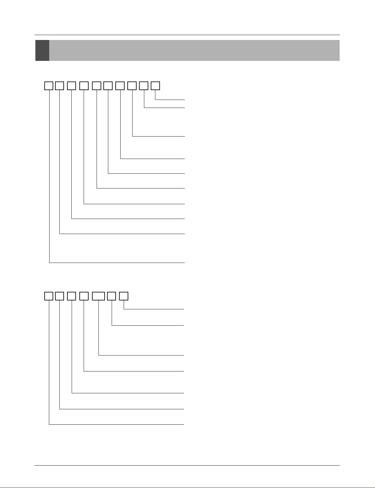
Model Number Nomenclature
Model Number Nomenclature
Indoor Unit
Outdoor Unit
A T N H 18 6 E L F B
Serial Number
Function
A : Basic
E : E/Grille
F : Plasma + Elevation grille
Panel type
Cassette L : Basic panel, W : Wooden panel
Duct : L
Chassis type
Cassette : E/F/D, Convertible : E/B, Duct : H/G/R
Electrical Rating
6 : 1Ø 220-240V ,50Hz
Nominal Cooling Capacity in Btu/h
Ex)18,000Btu/h '18', 24,000Btu/h '24'
Model Type
H : Heat Pump
Unit Type
N : Indoor Unit U : Outdoor Unit
Indoor Unit Type
T : Ceiling Cassette
V : Ceiling&Floor(Convertible)
B : Ceiling Concealed Duct
Refrigerent Type
A : R410A, L : R22
A U U H 100 8 0
Air Discharge Type
0 : Top discharge, A : Side discharge
Electrical Rating(Volt/Hertz/Phase)
1 : 115 / 60 / 1 2 : 220 / 60 / 1
3 : 208-230 / 60 / 1 5 : 200-220 / 50 / 1
6 : 220-240 / 50 / 1 8 : 380-415 / 50 / 3
Nominal Cooling Capacity in Btu/h
Ex)72,000Btu/h '72', 100,000Btu/h '100'
Model Type
W : DC Inverter Heat Pump(MPS Inverter)
H : Conventional Heat Pump(MPS Variable)
Unit Type
N : Indoor Unit, U : Outdoor Unit
Indoor Unit Type
2/3/4 : Multi Room, U : Universal, B : Duct, T : Cassette
Refrigerent Type
A : R410A, L : R22
Page 4
4 Synchro Air Conditioner
Safety Precautions
Safety Precautions
To prevent injury to the user or other people and property damage, the following instructions must
be followed.
■ Incorrect operation due to ignoring instruction will cause harm or damage. The seriousness is
classified by the following indications.
■ Meanings of symbols used in this manual are as shown below.
This symbol indicates the possibility of death or serious injury.
This symbol indicates the possibility of injury or damage to properties only.
Be sure not to do.
Be sure to follow the instruction.
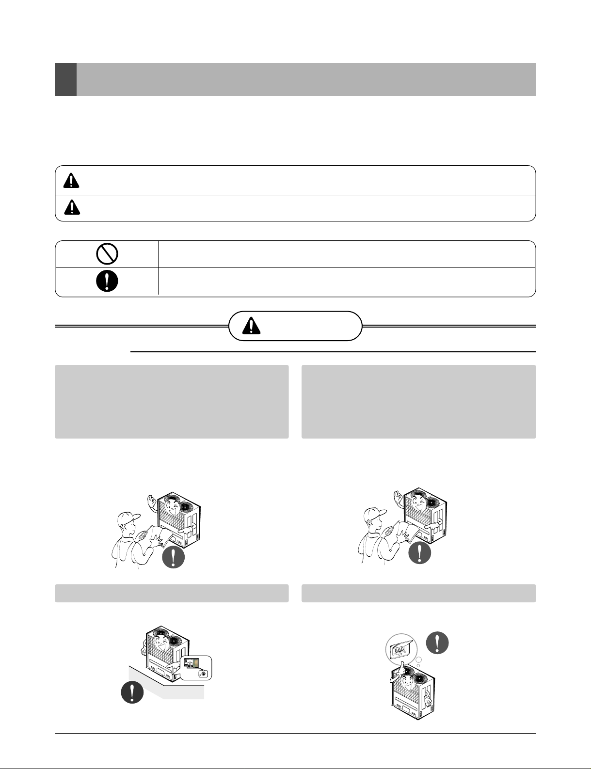
WARNING
■ Installation
Have all electric work done by a licensed
electrician according to "Electric Facility
Engineering Standard" and "Interior Wire
Regulations" and the instructions given in
this manual and always use a special circuit.
• If the power source capacity is inadequate or
electric work is performed improperly, electric
shock or fire may result.
Ask the dealer or an authorized technician to
install the air conditioner.
• Improper installation by the user may result in
water leakage, electric shock, or fire.
Always ground the product.
• There is risk of fire or electric shock.
Always intstall a dedicated circuit and breaker.
• Improper wiring or installation may cause fire or
electric shock.
WARNING
CAUTION
Page 5
Service Manual 5
Safety Precautions
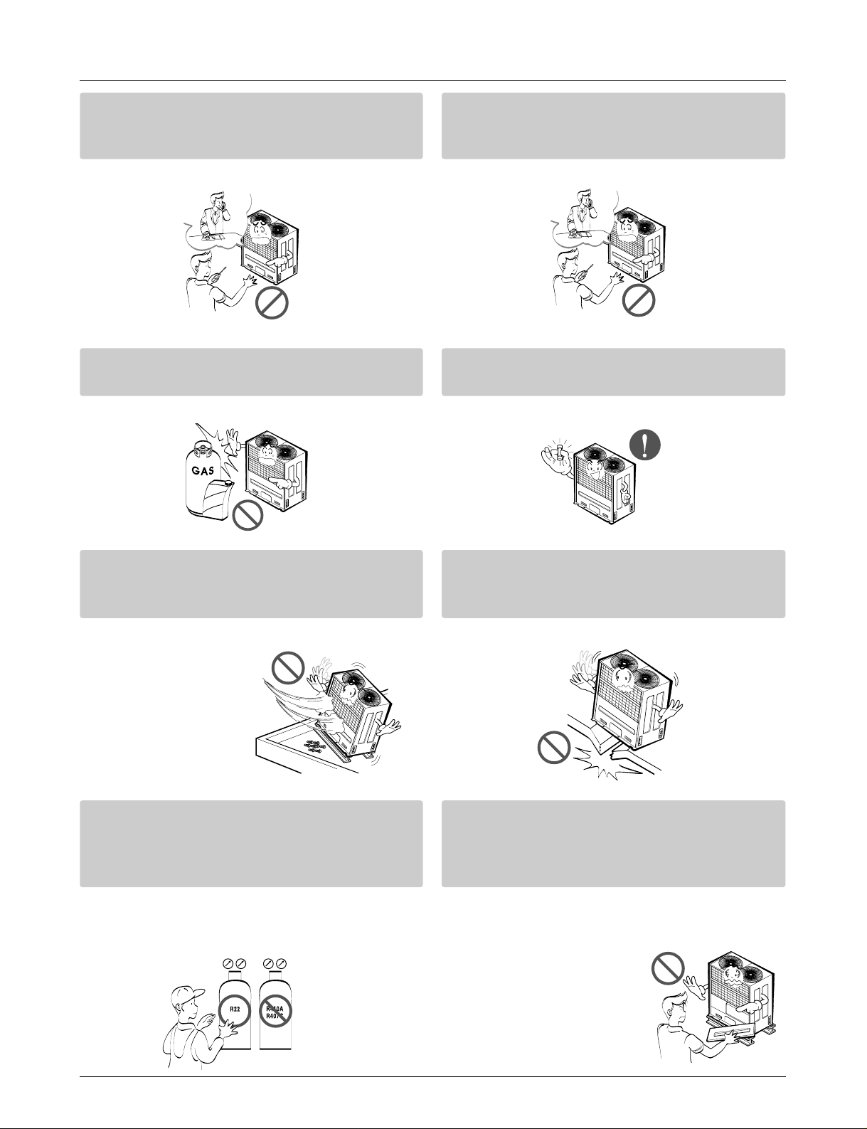
For re-installation of the installed product,
always contact a dealer or an Authorized
Service Center.
• There is risk of fire, electric shock, explosion, or
injury.
Do not install, remove, or re-install the unit
by yourself (customer).
• There is risk of fire, electric shock, explosion, or
injury.
Do not store or use flammable gas or
combustibles near the air conditioner.
• There is risk of fire or failure of product.
Use the correctly rated breaker or fuse.
• There is risk of fire or electric shock.
Prepare for strong wind or earthquake and
install the unit at the specified place.
• Improper installation may cause the unit to topple and result in injury.
Do not install the product on a defective
installation stand.
• It may cause injury, accident, or damage to the
product.
When installing and moving the air conditioner to another site, do not charge it with a
different refrigerant from the refrigerant
specified on the unit.
• If a different refrigerant or air is mixed with the
original refrigerant, the refrigerant cycle may
malfunction and the unit may be damaged.
Do not reconstruct to change the settings of
the protection devices.
• If the pressure switch, thermal switch, or other
protection device is shorted and operated
forcibly, or parts other than
those specified by LGE are
used, fire or explosion may
result.
Gasolin
Page 6
6 Synchro Air Conditioner
Safety Precautions
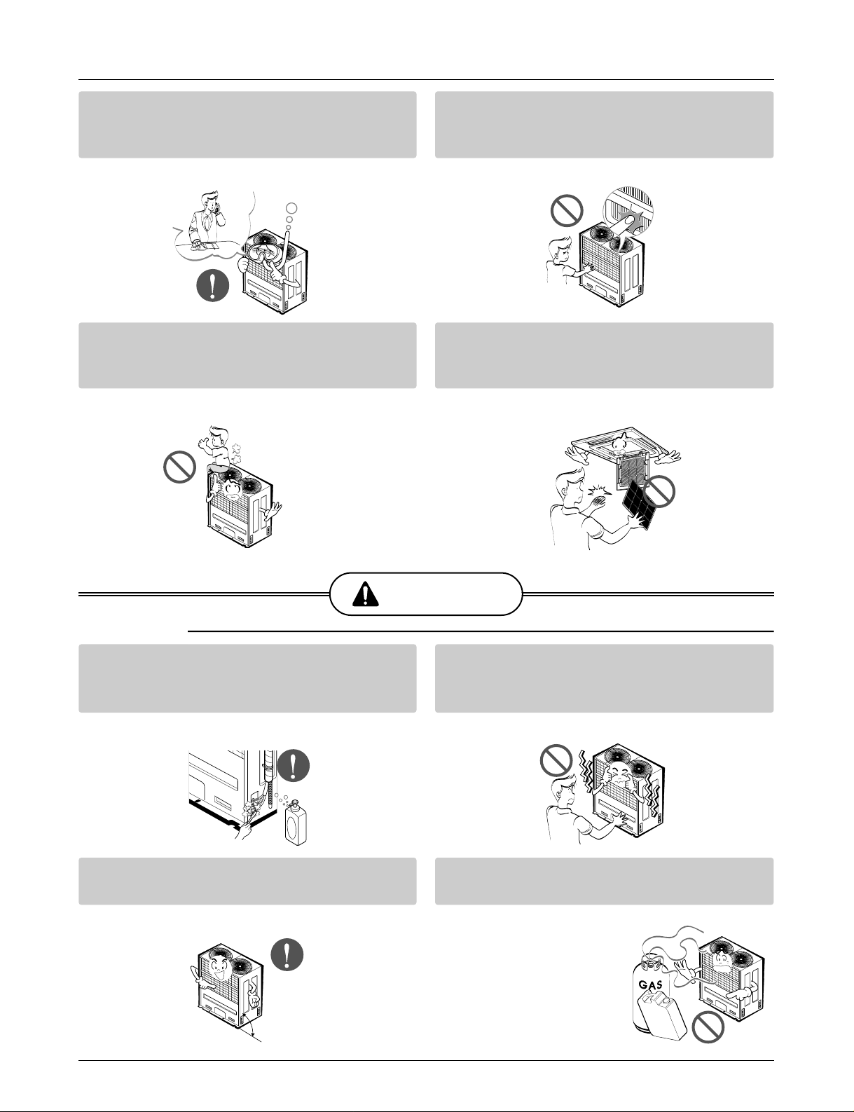
Ventilate before operating air conditioner
when gas leaked out.
• It may cause explosion, fire, and burn.
Securely install the cover of control box and
the panel.
• If the cover and panel are not installed securely,
dust or water may enter the outdoor unit and fire
or electric shock may result.
If the air conditioner is installed in a small room, measures must be taken to prevent the
refrigerant concentration from exceeding the safety limit when the refrigerant leaks.
• Consult the dealer regarding the appropriate measures to prevent the safety limit from being exceeded. Should the refrigerant leak and cause the safety limit to be exceeded, harzards due to lack of oxygen in the room could result.
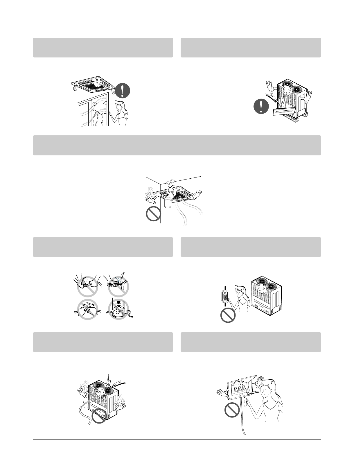
■ Operation
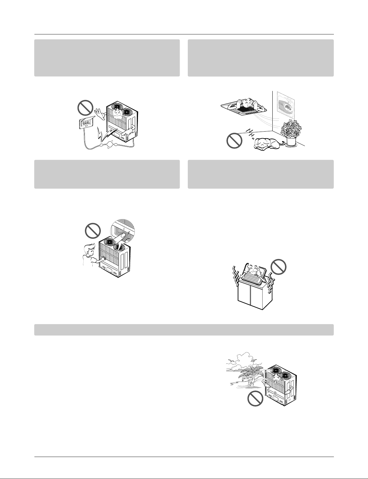
Do not damage or use an unspecified power
cord.
• There is risk of fire, electric shock, explosion, or
injury.
Use a dedicated outlet for this appliance.
• There is risk of fire or electrical shock.
Be cautious that water could not enter the
product.
• There is risk of fire, electric shock, or product
damage.
Do not touch the power switch with wet
hands.
• There is risk of fire, electric shock, explosion, or
injury.
Page 7
Service Manual 7
Safety Precautions
When the product is soaked (flooded or
submerged), contact an Authorized Service
Center.
• There is risk of fire or electric shock.
Be cautious not to touch the sharp edges
when installing.
• It may cause injury.
Take care to ensure that nobody could step
on or fall onto the outdoor unit.
• This could result in personal injury and product
damage.
Do not open the inlet grill of the product during operation. (Do not touch the electrostatic
filter, if the unit is so equipped.)
• There is risk of physical injury, electric shock, or
product failure.
CAUTION
■ Installation
Always check for gas (refrigerant) leakage
after installation or repair of product.
• Low refrigerant levels may cause failure of
product.
Do not install the product where the noise or
hot air from the outdoor unit could damage
the neighborhoods.
• It may cause a problem for your neighbors.
Keep level even when installing the product.
• To avoid vibration or water leakage.
Do not install the unit where combustible gas
may leak.
• If the gas leaks and accumulates around the
unit, an explosion may result.
90˚
Gasolin
Page 8
8 Synchro Air Conditioner
Safety Precautions
Use power cables of sufficient current
carrying capacity and rating.
• Cables that are too small may leak, generate
heat, and cause a fire.
Do not use the product for special purposes,
such as preserving foods, works of art, etc. It
is a consumer air conditioner, not a precision
refrigeration system.
• There is risk of damage or loss of property.
Keep the unit away from children. The heat
exchanger is very sharp.
• It can cause the injury, such as cutting the finger.
Also the damaged fin may result in degradation
of capacity.
When installting the unit in a hospital, communication station, or similar place, provide
sufficient protection against noise.
•
The inverter equipment, private power generator,
high-frequency medical equipment, or radio communication equipment may cause the air conditioner to operate erroneously, or fail to operate. On the
other hand, the air conditioner may affect such
equipment by creating noise that disturbs medical
treatment or image broadcasting.
Do not install the product where it is exposed to sea wind (salt spray) directly.
• It may cause corrosion on the product. Corrosion, particularly on the condenser and evaporator fins,
could cause product malfunction or inefficient operation.
Page 9

Service Manual 9
Safety Precautions
■ Operation
Do not use the air conditioner in special
environments.
• Oil, steam, sulfuric smoke, etc. can significantly
reduce the performance of the air conditioner or
damage its parts.
Do not block the inlet or outlet.
• It may cause failure of appliance or accident.
Make the connections securely so that the
outside force of the cablemay not be applied
to the terminals.
• Inadequate connection and fastening may generate heat and cause a fire.
Be sure the installation area does not deteriorate with age.
• If the base collapses, the air conditioner could
fall with it, causing property damage, product
failure, or personal injury.
Install and insulate the drain hose to ensure that water is drained away properly based on the
installation manual.
• A bad connection may cause water leakage.
Be very careful about product transportation.
• Only one person should not carry the product if it weighs more
than 20 kg.
• Some products use PP bands for packaging. Do not use any PP
bands for a means of transportation. It is dangerous.
• Do not touch the heat exchanger fins. Doing so may cut your fingers.
• When transporting the Outdoor Unit, suspending it at the specified
positions on the unit base. Also support the Outdoor Unit at four
points so that it cannot slip sideways.
Page 10
10 Synchro Air Conditioner
Safety Precautions
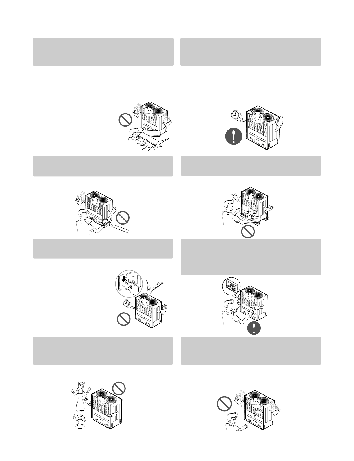
Safely dispose of the packing materials.
•
Packing materials, such as nails and other metal or
wooden parts, may cause stabs or other injuries.
•
Tear apart and throw away plastic packaging bags
so that children may not play with them. If children
play with a plastic bag which was
not torn apart, they face the
risk of suffocation.
Turn on the power at least 12 hours before
starting operation.(In case of outdoor
temperature 5°C below)
• Starting operation immediately after turning on
the main power switch can result in severe
damage to internal parts. Keep the power switch
turned on during the operational season.
Do not touch any of the refrigerant piping
during and after operation.
• It can cause a burn or frostbite.
Do not operate the air conditioner with the
panels or guards removed.
• Rotating, hot, or high-voltage parts can cause
injuries.
Do not directly turn off the main power
switch after stopping operation.
• Wait at least 5 minutes before turning off the
main power switch.
Otherwise it may result in
water leakage or other
problems.
Auto-addressing should be done in condition of
connecting the power of all indoor and outdoour
units. Auto-addressing should also be done in
case of changing the Indoor Unit board(PCB).
Use a firm stool or ladder when cleaning or
maintaining the air conditioner.
• Be careful and avoid personal injury.
Do not insert hands or other objects through
the air inlet or outlet while the air conditioner
is plugged in.
• There are sharp and moving parts that could
cause personal injury.
Page 11
Service Manual 11
Model Names
Model Names
Indoor Unit
Outdoor Unit
Branch Kit
TE
Ceiling Cassette 4-Way TF
TD
Ceiling & Floor(Convertible)
VE
VB
BH
Ceiling Concealed Duct BG
BR
Model Name
Nominal Capacity[Btu/h(Kw)]
Chassis
Name
Type
12,000
(3.5)
18,000
(5.3)
24,000
(7.0)
30,000
(8.8)
36,000
(10.6)
48,000
(14.1)
60,000
(17.6)
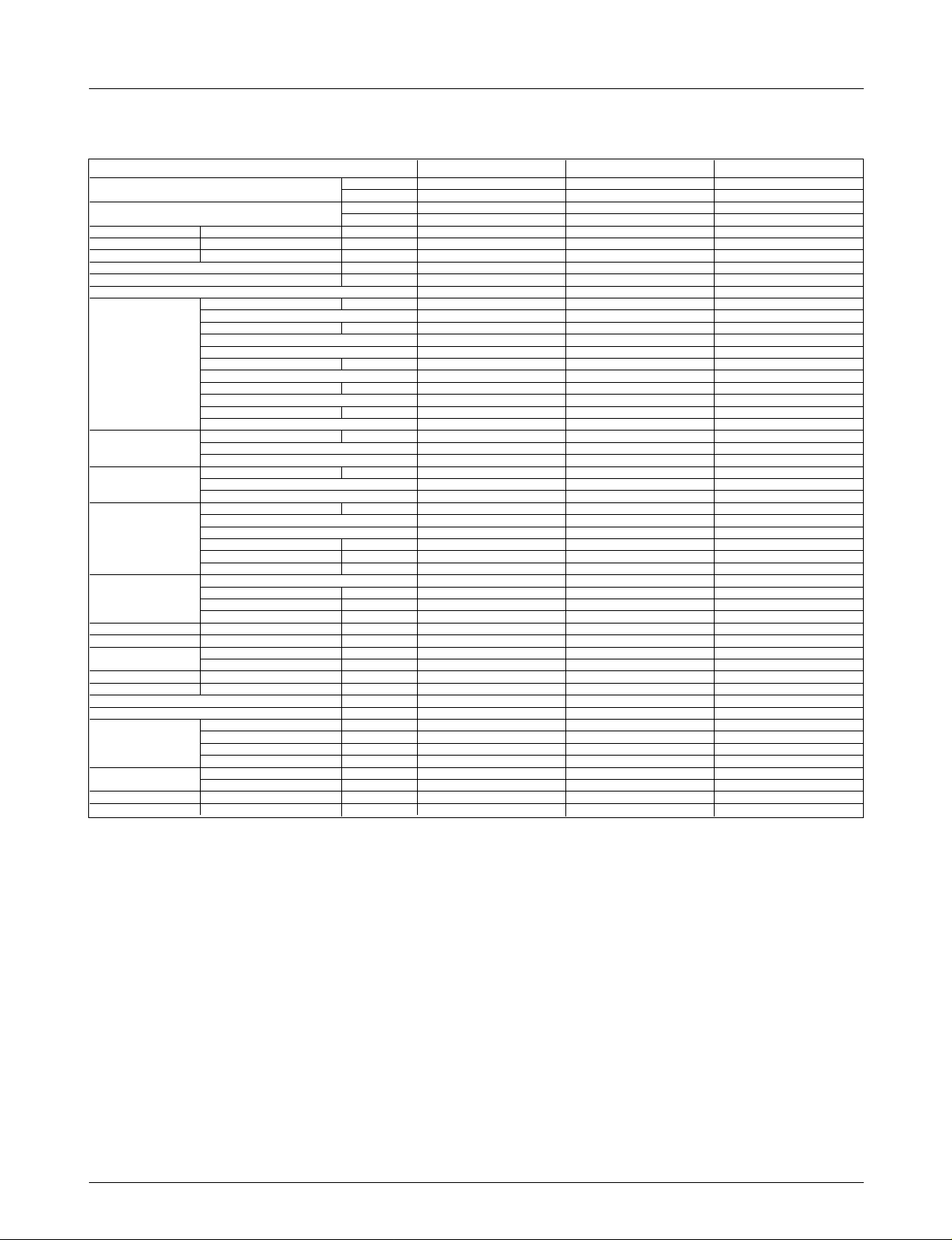
ATNH126ELFC ATNH186ELFC - - - -
- - ATNH246FLFC ATNH306FLFC - -
- - - - ATNH366DLFC ATNH486DLFC ATNH606DLFC
AVNH126ELAC - - - - -
- AVNH186BLAC AVNH246BLAC AVNH306BLAC - -
- ABNH186HLAC ABNH246HLAC - - -
- - - ABNH306GLAC ABNH366GLAC -
- - - - - ABNH486RLAC ABNH606RLAC
Indoor Unit
UH AUUH488C - - -
MPS Variable UY - - AUUH 728C -
UW - - - AUUH1008C
Model Name
Nominal Capacity[Btu/h(Kw)]
Type
Chassis
Name
48,000
(14.0)
60,000
(17.6)
72,000
(21.1)
100,000
(29.0)
Outdoor Unit
Name of accessory
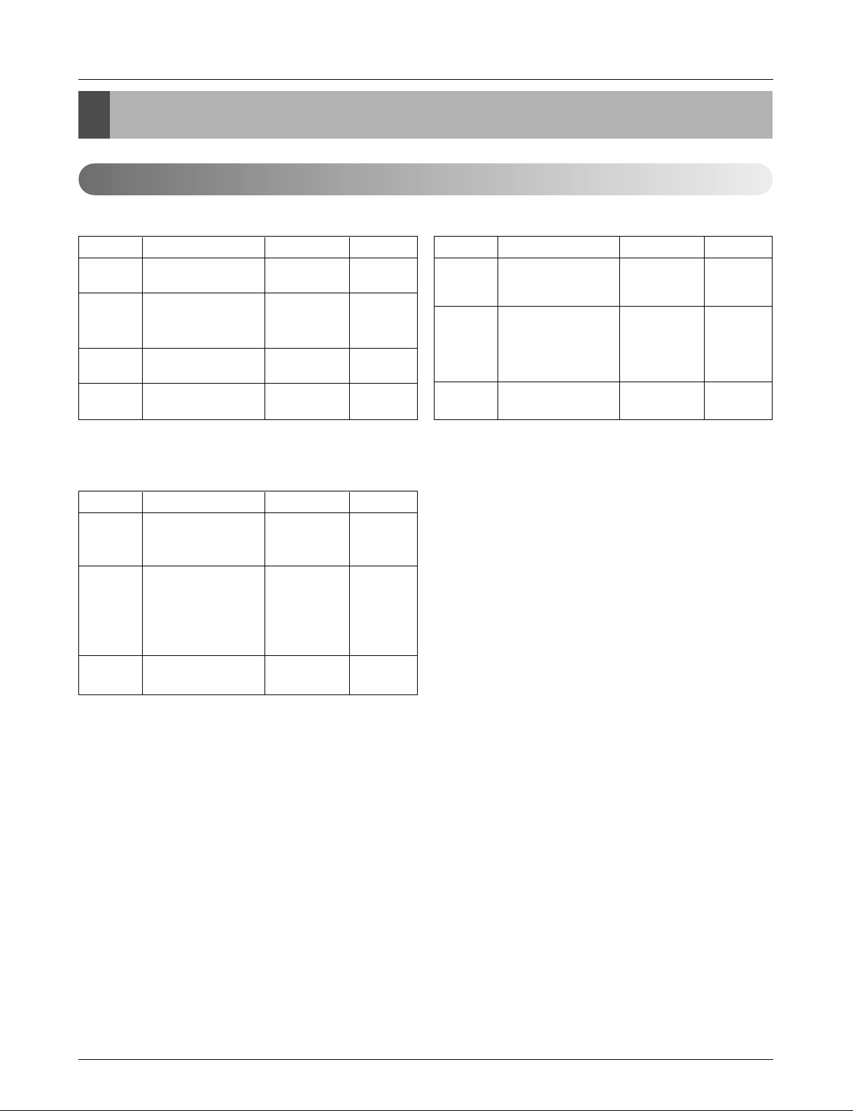
Model No. Indoor classification Capacity Ratio(%) Remark
PMUB11A
"Synchro" Duo
50:50(1:1)
PMUB23A 40:60(2:3) Unbalance type
Branch Kit
PMUB111A 33:33:33(1:1:1)
PMUB112A "Synchro" Trio 25:25:50(1:1:2) Unbalance type
PMUB122A 20:40:40(1:2:2) Unbalance type
PMUB1111A "Synchro" Quartet 25:25:25:25(1:1:1:1)
Page 12
12 Synchro Air Conditioner
External Appearance
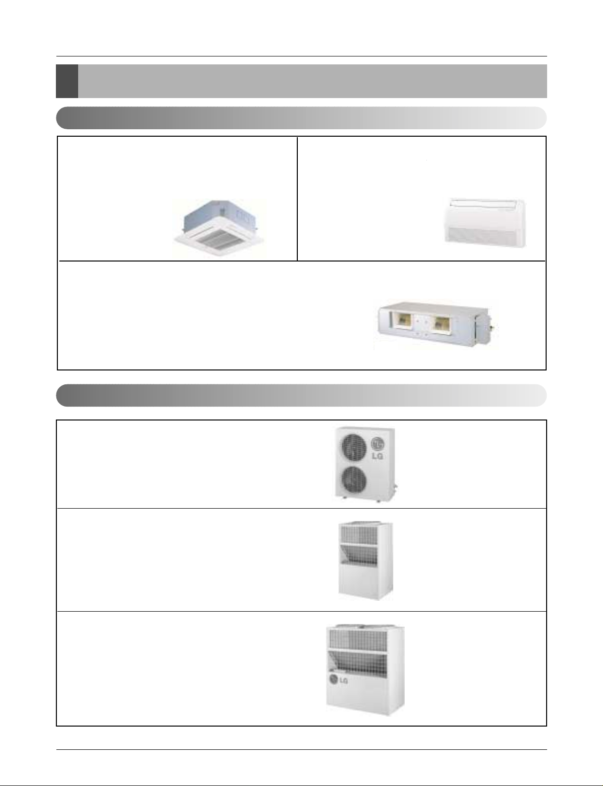
External Appearance
Indoor Unit
Outdoor Unit
Ceiling Cassette-4Way Ceiling & Floor(Convertible)
Ceiling Concealed Duct
ATNH126ELFC / ATNH186ELFC
ATNH246FLFC / ATNH306FLFC
ATNH366DLFC / ATNH486DLFC
ATNH606DLFC
AVNH126ELAC / AVNH186BLAC
AVNH246BLAC / AVNH306BLAC
ABNH186HLAC / ABNH246BHLAC
ABNH306GLAC / ABNH366BGLAC
ABNH486RLAC / ABNH606RLAC
AUUH728C
AUUH488C
AUUH1008C
Page 13
Service Manual 13
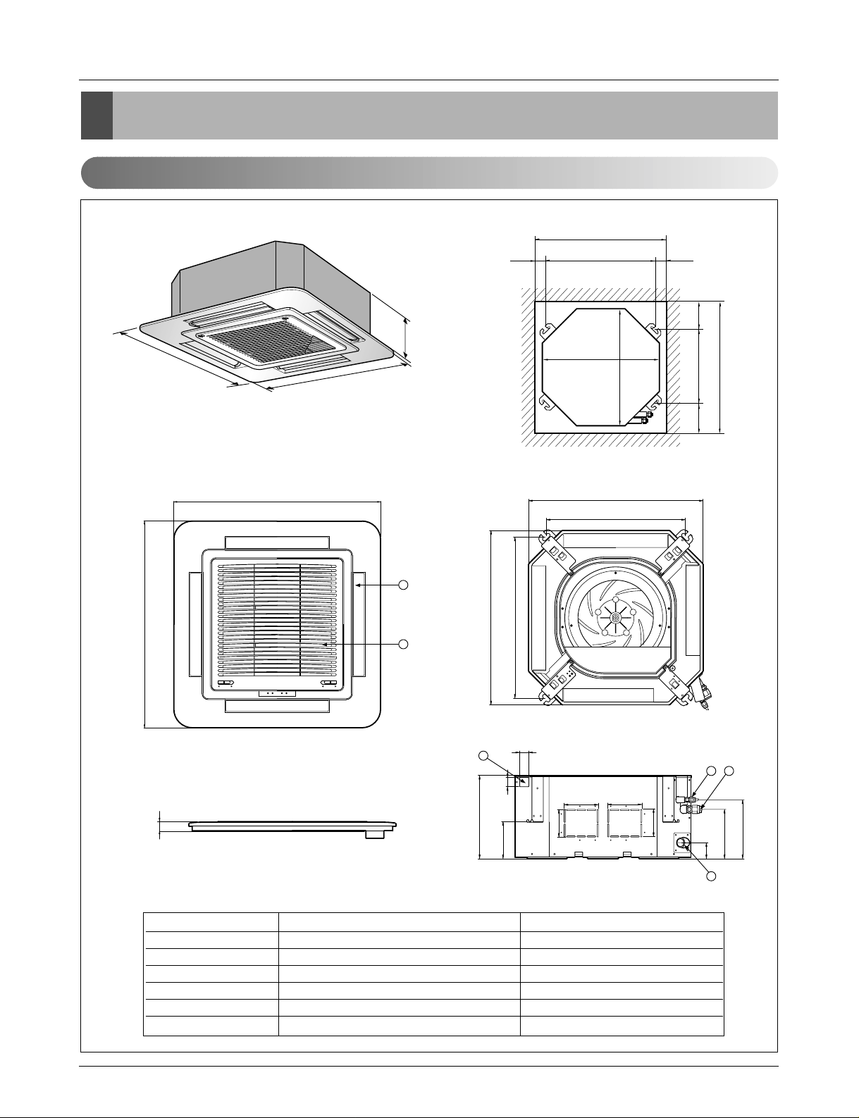
Dimensions
Dimensions
Indoor Unit
CLOSE OPEN OPEN CLOSE
269
670
30
570
269
190.5
160
52
90
90
120.4
30
521
670
570
450
40
110 110
670
670
4
132
5
6
Unit:mm
570 Unit size
570 Unit size
450 (Hanging bolt)
7575
600 (Ceiling opening)
600 (Ceiling opening)
521(Hanging bolt)
39.5
39.5
1. Cassette Type - TE(12K/18K)
(unit : mm)
Number Name Descripition
1 Liquid pipe connection ø6.35 flare
2 Gas pipe connection
12k: ø9.52, 18k: ø12.7 flare
3 Drain pipe connection
4 Power supply connection
5 Air discharge grill
6 Air suction grill
Page 14
14 Synchro Air Conditioner
Dimensions
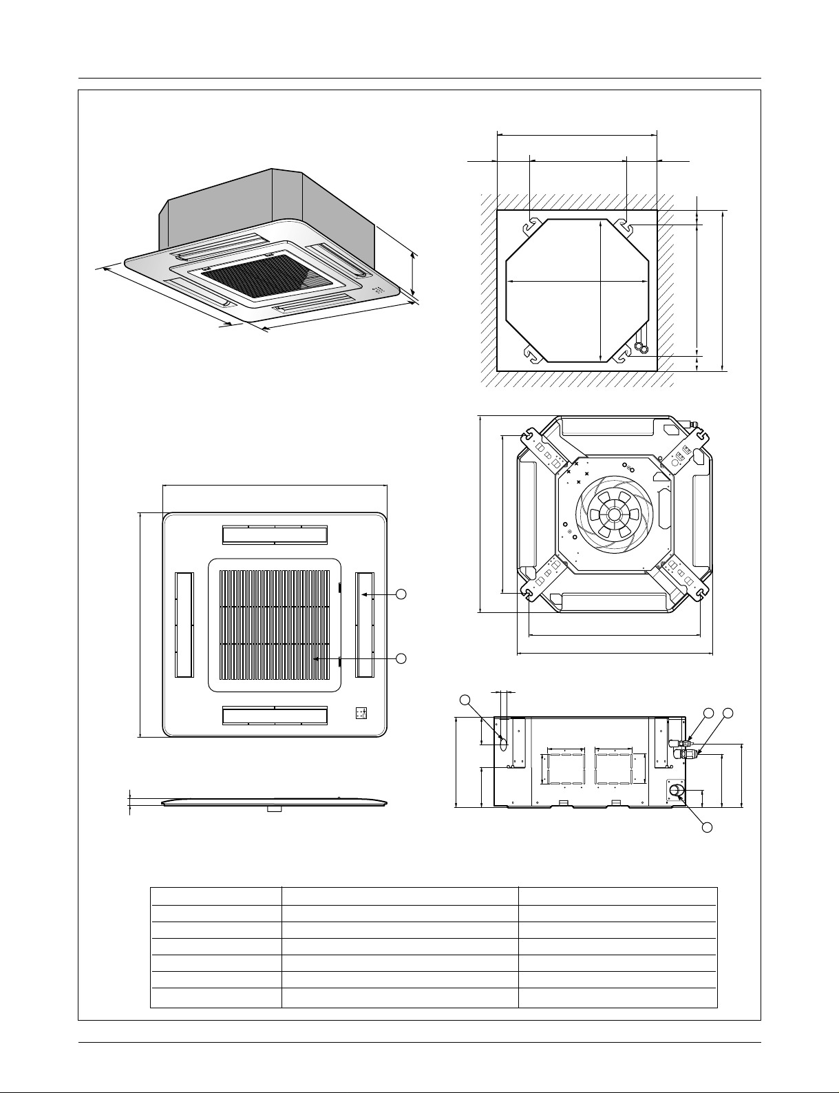
2. Cassette Type - TF (24K/30K)
292
850
850
850
850
744
658
572
744
292
212
150
54
90
90
192 117
70
110 110
4
132
5
6
Unit:mm
744 Unit size
744 Unit size
658 (Hanging bolt)
6666
790 (Ceiling opening)
790 (Ceiling opening)
572(Hanging bolt)
109
109
30
(unit : mm)
Number Name Descripition
1 Liquid pipe connection ø6.35 flare
2 Gas pipe connection
24K: ø12.7, 30K: ø15.88 flare
3 Drain pipe connection
4 Power supply connection
5 Air discharge grill
6 Air suction grill
Page 15
Service Manual 15
Dimensions
288
950
950
950
950
290
210.5
180
52
140
40
110
30
90
90
110
55
840
785
840
678
Fresh Air Inlet
Unit:mm
840 Unit size
840 Unit size
672 (Hanging bolt)
101.5101.5
875 (Ceiling opening)
875 (Ceiling opening)
785 (Hanging bolt)
45
45
4
5
6
1
3
2
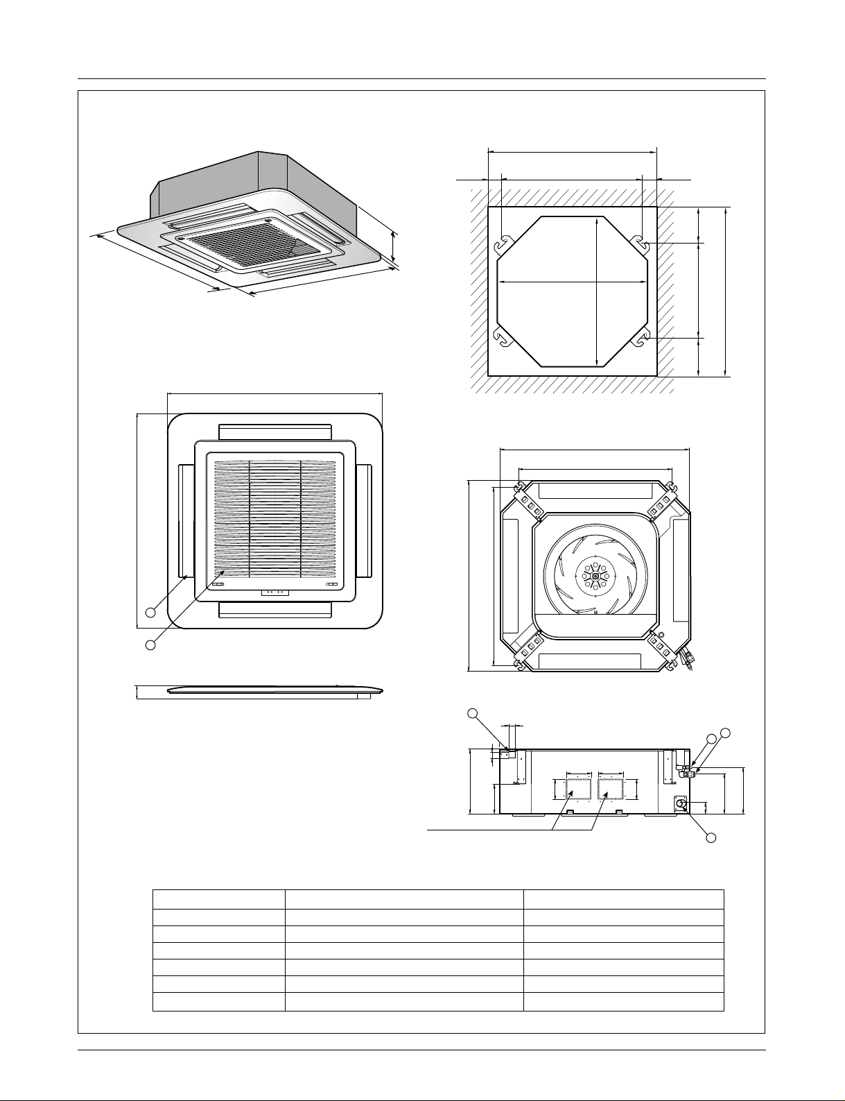
(unit : mm)
Number Name Descripition
1 Liquid pipe connection
36K: ø6.35, 48K/60K: ø9.52 flare
2 Gas pipe connection
36K: ø15.88, 48K/60K: ø19.05 flare
3 Drain pipe connection
4 Power supply connection
5 Air discharge grill
6 Air suction grill
3. Cassette Type - TD(36K/48K/60K)
Page 16
16 Synchro Air Conditioner
Dimensions
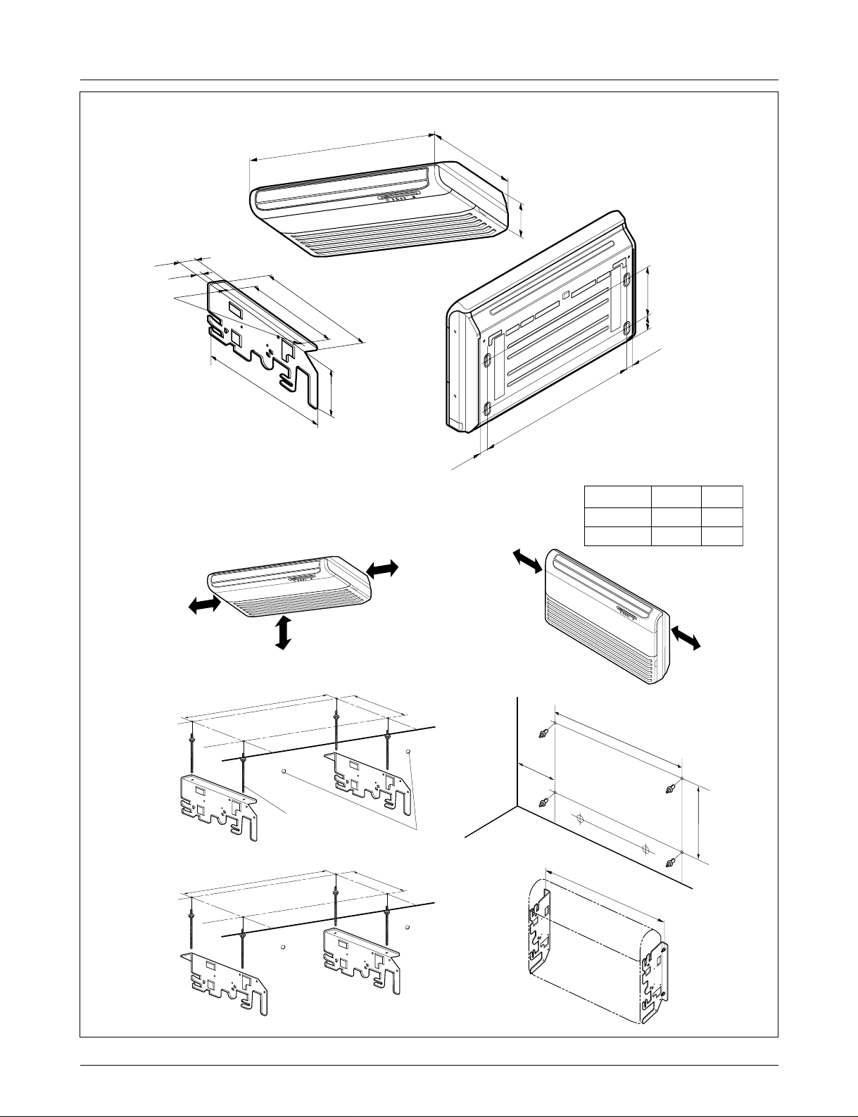
4. Ceiling & Floor(Convertible) - VB(18K/24K), VE(12K)
63
Ø10 Stud Bolt hole
1200
R
38
392
265
468
175
(Installation Plate)
615
205
076
1
(Rear Side)
250
128
36
(Unit: mm)
More than
20cm
36
More than
20cm
Note:
1. Pipe Specification(mm)
GasLiquidModel
Ø 12.7Ø 6.3518k, 24k
Ø 15.88Ø 6.3530k
More than
20cm
More than eye-level
R
(Ceiling installation)
1076
Suspension bolt
(W3/8 or M10)
1236
265
Center-line for the
piping hole
265
(Floor/Wall installation)
more than
260
1236
1076
More than
R
20cm
265
Page 17
Service Manual 17
Dimensions
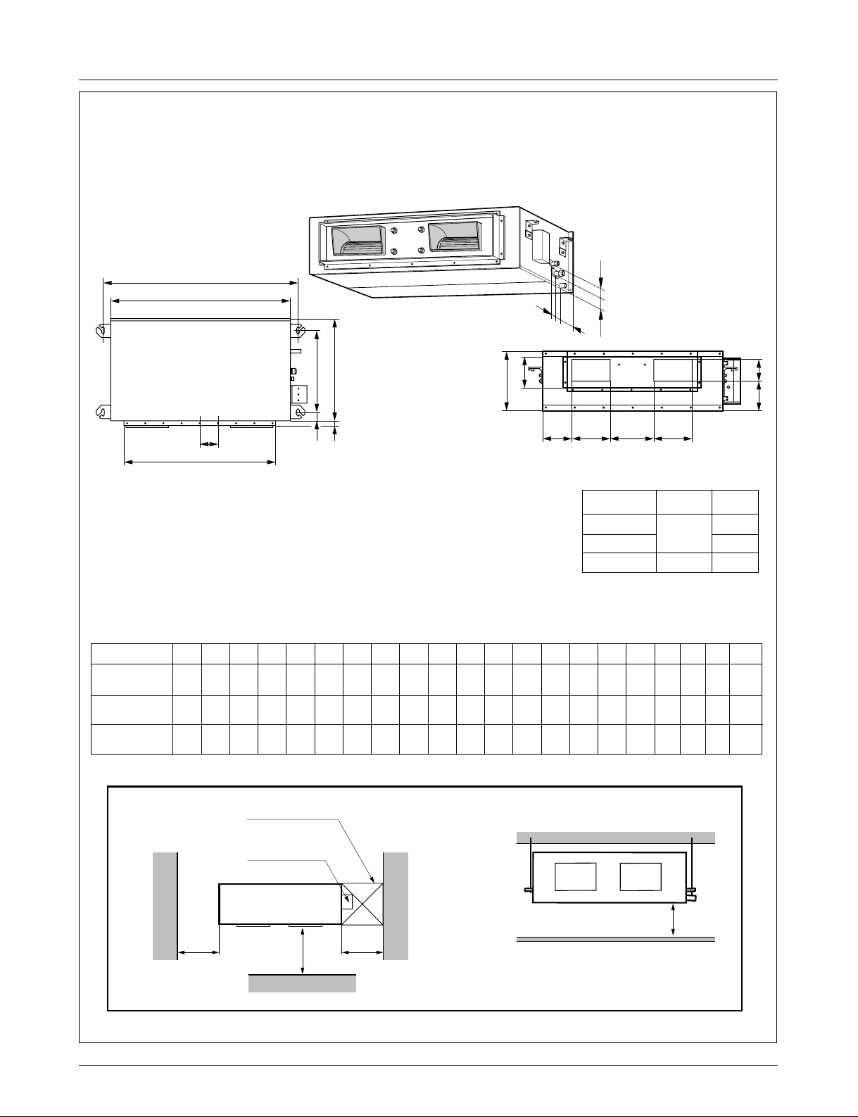
Top view
(unit: mm)
Front view
600600
Front
Inspection hole
※Suitable dimension "H" is necessary
to get a slope to drain as figure.
(600X600)
Control box
1000
H
l
i
h
j
k
A
H
CD
EF
B
(G)
ab c d
K
J
fe
Ø 12.7
Ø 15.88
Ø 6.35
Ø 9.52
18, 24k
30, 36
Ø 19.05
48, 60k
k
GasLiquidModel
1. Pipe Specification(mm)
Note:
C D E F (G) H J K a b c d e f h i j k l
355 45.5 450 30 87 750 163 260 61.5 243 212.3 243 110 130 52 66 81 30 158.5
355 45.5 450 30 87 830 186 298 229.5 243 232 243 116 160 53 59 81 19 158.5
477 56 590 30 120 1006 294 380 215 279 241 279 185 168 51 98 83 17 172
Capacity A B
932 882
1232 1182
1282 1230
ABNH186HLAC
ABNH246HLAC
ABNH306GLAC
ABNH366GLAC
ABNH486RLAC
ABNH606RLAC
(Unit: mm)
5. Ceiling Concealed Duct - BH(18K/24K), BG(30K/36K), BR(48K/60K)
Page 18
18 Synchro Air Conditioner
Dimensions
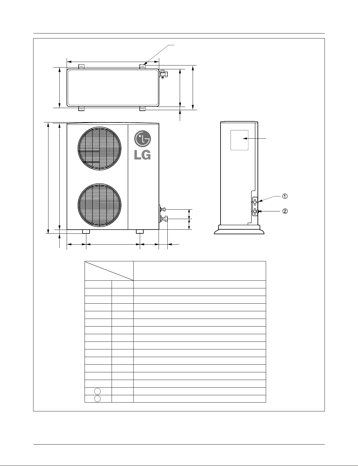
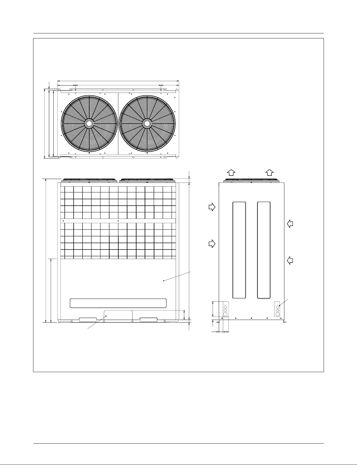
AUUH488C
L3
H
L4
W
4-hole for anchor bolts
D
L1
L2
L11
Control cover
Liquid side
3-way valve
Gas side
3-way valve
L5
L6L7 L8 L9
Model
Dimensions
AUUH488C
Wmm 900
Hmm 1
Dmm
L1 mm
L2 mm
L3 mm
L4 mm
L5 mm
L6 mm
L7 mm
L8 mm
L9 mm
L10 mm
L11
1
2
mm
mm Ø9.52
mm Ø19.05
L10
,165
370
460
45
410
1,135
30
550
175
175
112
120
83
Page 19
Service Manual 19
Dimensions
AUUH728C
Air
inlet
Air
inlet
Air outlet
Service Panel
(Unit : mm)
Knockout hole
(For the control wiring,
the power supply,
refrigerant connecting
pipe)
Knockout hole
(For the control wiring, the power supply,
refrigerant connecting pipe)
153
15
690
40
144428
100
220
1512
670
730
153
806
500(bolt hole)
700(bolt hole)
Page 20
20 Synchro Air Conditioner
Dimensions
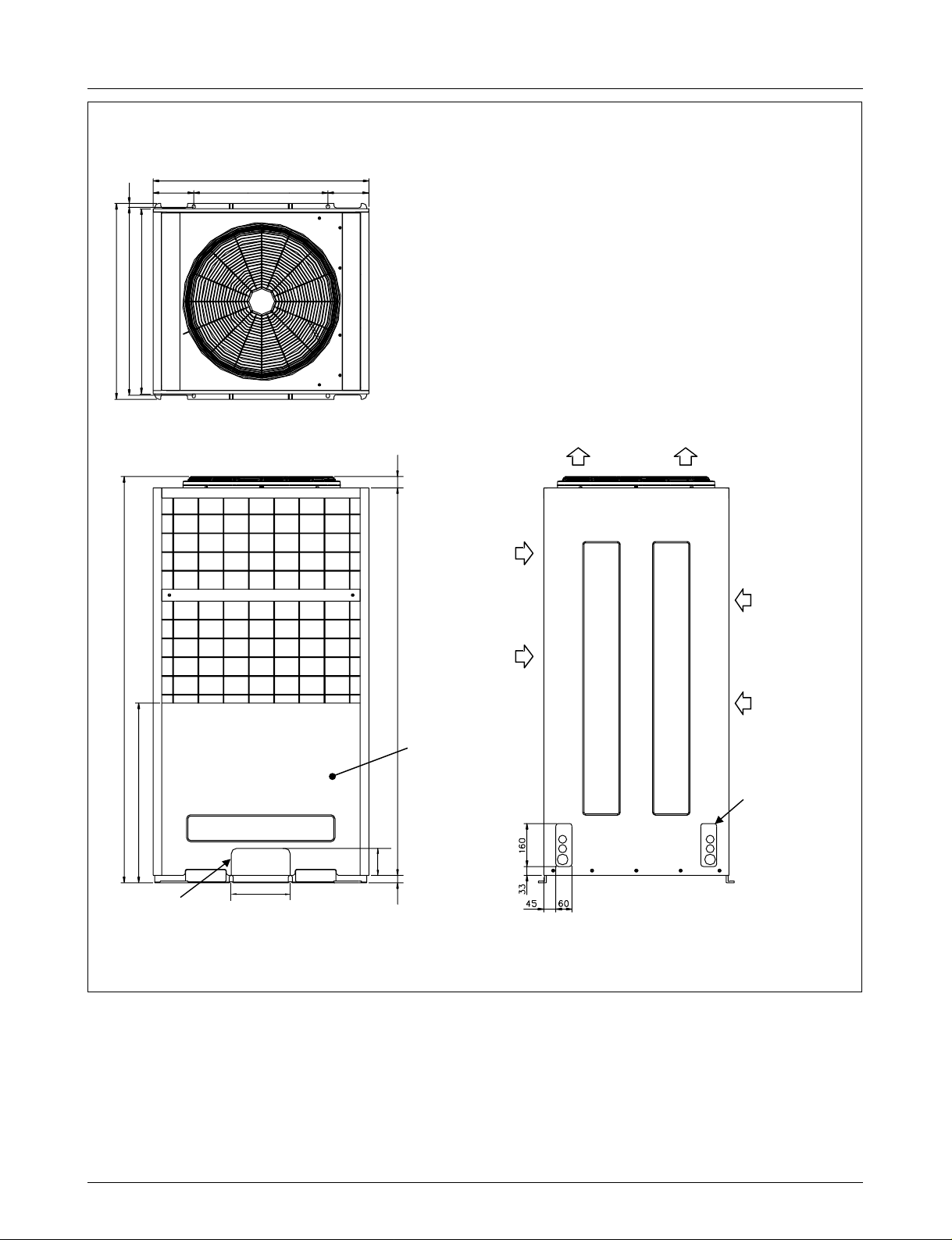
AUUH1008C
15
730
700(bolt hole)
1555
190 900(bolt hole)
690
1280
190
48
Air outlet
Air
inlet
Air
inlet
Service Panel
670
Knockout hole
(For the control wiring,
the power supply,
refrigerant connecting
pipe)
Knockout hole
100
63 1444
33 160
45
60
(For the control wiring, the power supply,
refrigerant connecting pipe)
Page 21
Service Manual 21
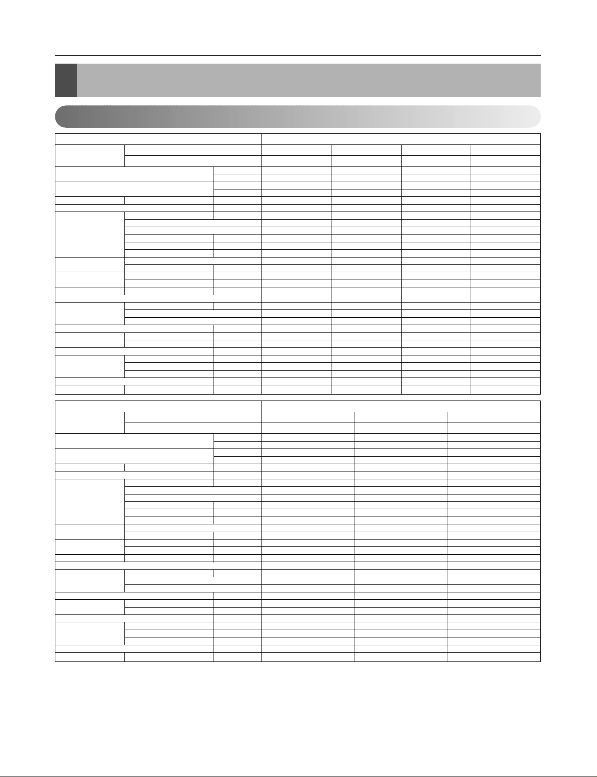
Product Specifications
3024(3517) 4536(5275) 6048(7033) 7056(8205)
12000 18000 24000 28000
3478(4044) 5116(5949) 6955(8089) 8114(9437)
13800 20300 27600 32200
9.5/8/7(336/283/247) 13/12/11(459/424/388) 15/14/13(523/494/459) 19/17/15(671/600/550)
18~30/16~30 18~30/16~30 18~30/16~30 18~30/16~30
18.3 22.4 40.3 48.6
IC-9630LGAE IC-9630LGAC OBM-3502P2 OBM-4105P2
6666
75 90 121 146
0.35 0.75 0.53 0.67
2.5/440 2.5/440 4/440 4/440
Turbo Fan Turbo Fan Turbo Fan Turbo Fan
1/13.0(330) 1/13.0(330) 1/15.0(382) 1/15.0(382)
670/620/550 720/670/620 600/540/480 650/600/550
670/620/550 720/670/620 600/540/480 650/600/550
38 / 35 / 32 41 / 39 / 37 43 / 41 / 39 45 / 42 / 39
Thermistor Thermistor Thermistor Thermistor
0.275(7.0) 0.275(7.0) 0.275(7.0) 0.275(7.0)
19 19 21 21
2R11C 2R11C 2R12C 2R12C
1.2 2.4 3 3.3
22.4*10.5*22.4 (570*269*570) 22.4*10.5*22.4 (570*269*570) 29.3*11.5*29.3 (744*292*744) 29.3*11.5*29. (744*292*744)
26.4*1.2*26.4 (670*30*670) 26.4*1.2*26.4 (670*30*670) 33.5*1.2*33.5 (850*30*850) 33.5*1.2*33.5 (850*30*850)
19(41.9) 19(41.9) 24(52.9) 24(52.9)
1/4(6.35) 1/4(6.35) 1/4(6.35) 1/4(6.35)
3/8(9.52) 1/2(12.7) 1/2(12.7) 5/8(15.88)
1.26(32) 1.26(32) 1.26(32) 1.26(32)
25.2*13.0*25.2 (640*330*640) 25.2*13.0*25.2 (640*330*640) 32.6*14.4*32.6 (828*365*828) 32.6*14.4*32.6 (828*365*828)
189/378 189/378 84/168 84/168
Rated Cooling Capacity kcal/hr(W)
Btu/hr
Ratedl Heating Capacity kcal/hr(W)
Btu/hr
Air Circulation Indoor(H/M/L)
CMM(CFM)
Setting temperature range °C
Fan motor Output W
Model
No. of Poles
Input W
Running Current A
Capacitor µF/Vac
Fan Type
No. Used / Diameter EA/inch(mm)
Fan RPM Cooling(H/M/L) rpm
Heating(H/M/L) rpm
Noise Level
(Sound Press,1m)
H/M/L dBA
Temperature controller
Coil Tube Size (OD) inch(mm)
Fins per inch
No. of Rows & Column
Dehumidification Rate l/h
Dimensions (W*H*D) Indoor inch(mm)
Panel inch(mm)
Net Weight kg(lbs)
Piping Liquid inch(mm)
Connection Gas inch(mm)
Drain hose (ID Ø)mm
Packing Dimension (W*H*D) inch(mm)
Stuffing Quantity
Without(Without) S/Parts 20/40ft
Ceiling Cassette - 4way
ATNH126ELFC
PT-HEC1
ATNH186ELFC
PT-HEC1
ATNH246FLFC
PT-HFC(F)
ATNH306FLFC
PT-HFC(F)
Indoor Unit Type
Model Indoor unit
Decoration panel
9072(10549) 12095(14067) 14112(16412)
36000 48000 56000
10433(12130) 13305(15474) 15523(18053)
41400 52800 61600
25/23/21(883/812/742) 30/28/26(1059/988/918) 34/32/30(1200/1130/1059)
18~30/16~30 18~30/16~30 18~30/16~30
52.5 58.5 107
IC-1630LGPJ IC-1640LGPH IC-14640LGPM
66 6
175 195 237
0.76 1.5 1.8
4/440 6/400 6/400
Turbo Fan Turbo Fan Turbo Fan
1/18.1(460) 1/18.1(460) 1/18.1(460)
550/510/470 600/555/520 700/650/600
550/510/470 600/555/520 700/650/600
40 / 38 / 36 43 / 41 / 39 50 / 47 / 43
Thermistor Thermistor Thermistor
0.275(7.0) 0.275(7.0) 0.275(7.0)
21 21 21
2R 12C 2R 12C 2R 12C
4 5.5 6.5
33.1*11.3*33.1 (840*288*840) 33.1*11.3*33.1 (840*288*840) 33.1*11.3*33.1 (840*288*840)
37.4*1.2*37.4 (950*30*950) 37.4*1.2*37.4 (950*30*950) 37.4*1.2*37.4 (950*30*950)
32(70.4) 32(70.4) 32(70.4)
1/4(6.35) 3/8(9.52) 3/8(9.52)
5/8(15.88) 3/4(19.05) 3/4(19.05)
1.26(32) 1.26(32) 1.26(32)
36.4*13.8*36.4 (925*350*925) 36.4*13.8*36.4 (925*350*925) 36.4*13.8*36.4 (925*350*925)
72/144 72/144 72/144
Rated Cooling Capacity kcal/hr(W)
Btu/hr
Ratedl Heating Capacity kcal/hr(W)
Btu/hr
Air Circulation Indoor(H/M/L)
CMM(CFM)
Setting temperature range °C
Fan motor Output W
Model
No. of Poles
Input W
Running Current A
Capacitor µF/Vac
Fan Type
No. Used / Diameter EA/inch(mm)
Fan RPM Cooling(H/M/L) rpm
Heating(H/M/L) rpm
Noise Level
(Sound Press,1m)
H/M/L dBA
Temperature controller
Coil Tube Size (OD) inch(mm)
Fins per inch
No. of Rows & Column
Dehumidification Rate l/h
Dimensions (W*H*D) Indoor inch(mm)
Panel inch(mm)
Net Weight kg(lbs)
Piping Liquid inch(mm)
Connection Gas inch(mm)
Drain hose (ID Ø)mm
Packing Dimension (W*H*D) inch(mm)
Stuffing Quantity
Without(Without) S/Parts 20/40ft
Ceiling Cassette - 4way
ATNH366DLFC
PT-HDC1
ATNH486DLFC
PT-HC1
ATNH606DLFC
PT-HDC1
Indoor Unit Type
Model Indoor unit
Decoration panel
Product Specifications
Indoor Unit
Notes:
1. Capacities are based on the following conditions:
Cooling : - Indoor Temperature 27˚C(80.6˚F) DB / 19˚C(66.2˚F) WB
- Outdoor Temperature 35˚C(95˚F) DB / 24˚C(75.2˚F) WB
- Interconnecting Piping Length 7.5m
- Level Difference of Zero.
Heating : - Indoor Temperature 20˚C(68˚F) DB / 15˚C(59˚F) WB
- Outdoor Temperature 7˚C(44.6˚F) DB / 6˚C(42.8˚F) WB
- Interconnecting Piping Length 7.5m
- Level Difference of Zero.
2. Capacities are Net Capacities.
3. Due to our policy of innovation some specifications may be changed without notification.
Page 22
22 Synchro Air Conditioner
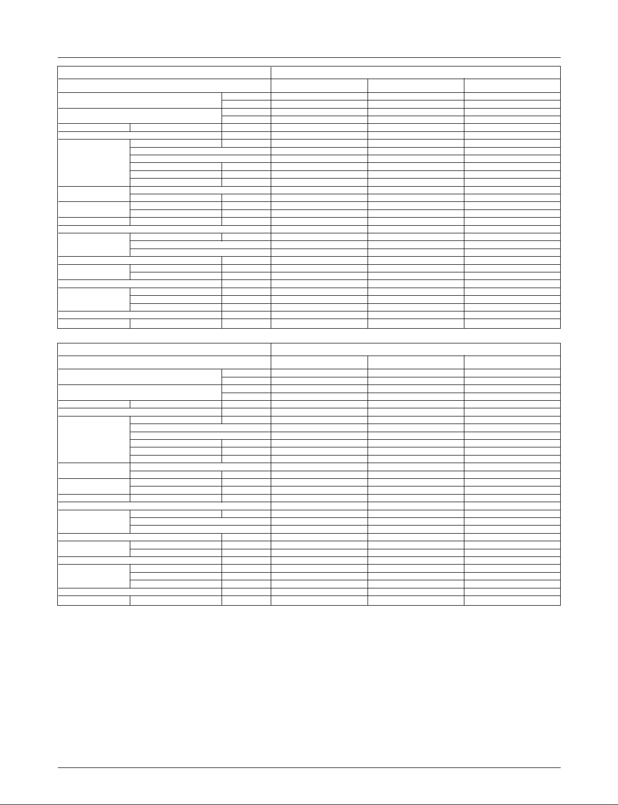
Product Specifications
4536(5275) 6048(7034) 7560(8791)
18000 24000 30000
5116(5949) 6955(8089) 8694(10110)
20300 27600 34500
16.5/14.5/13(583/512/459) 18/16.5/14(636/583/494) 26.5/23/20(936/812/706)
8810
18~30/16~30 18~30/16~30 18~30/16~30
118 118 211
IC-13450LG13C IC-13450LG13C IC-13450LG13J
44 4
180 180 300
0.92 0.92 1.34
6/370 6/370 6/370
Sirocco Fan Sirocco Fan Sirocco Fan
2/6.97(177) 2/6.97(177) 2/6.97(177)
1350/1310/1270 1410/1350/1250 1415/1360/1290
1350/1310/1270 1410/1350/1250 1415/1360/1290
36 / 34 /32 38 / 36 /34 40 / 38 /35
Thermistor Thermistor Thermistor
0.275(7.0) 0.275(7.0) 0.275(7.0)
21 21 21
2R 10C 3R 10C 3R 12C
2 2.5 3.3
34.6*10.2*17.7 (880*260*450) 34.6*10.2*17.7 (880*260*450) 46.5*11.7*17.7 (1180*298*450)
35(77.2) 35(77.2) 38(84)
1/4(6.35) 1/4(6.35) 1/4(6.35)
1/2(12.7) 1/2(12.7) 5/8(15.88)
25.4 25.4 25.4
44.7*13.4*22.0 (1135*340*565) 44.7*13.4*22.0 (1135*340*565) 56.5*14.8*22.9 (1435*375*582)
120/252 120/252 95/191
Rated Cooling Capacity kcal/hr(W)
Btu/hr
Ratedl Heating Capacity kcal/hr(W)
Btu/hr
Air Circulation Indoor(H/M/L)
CMM(CFM)
Setting temperature range °C
Fan motor Output W
Model
No. of Poles
Input W
Running Current A
Capacitor µF/Vac
Fan Type
No. Used / Diameter EA/inch(mm)
Fan RPM Cooling(H/M/L) rpm
Heating(H/M/L) rpm
Noise Level
(Sound Press,1m)
H/M/L dBA
Temperature controller
Coil Tube Size (OD) inch(mm)
Fins per inch
No. of Rows & Column
Dehumidification Rate l/h
Dimensions (W*H*D) Indoor inch(mm)
Panel inch(mm)
Net Weight kg(lbs)
Piping Liquid inch(mm)
Connection Gas inch(mm)
Drain hose (ID Ø)mm
Packing Dimension (W*H*D) inch(mm)
Stuffing Quantity
Without(Without) S/Parts 20/40ft
Ceiling Concealed Duct - High Static
ABNH186HLAC ABNH246HLAC ABNH306GLAC
Indoor Unit Type
Model
9072(10549) 12095(14067) 14112(16412)
36000 48000 56000
10433(12130) 13305(15474) 15523(18053)
41400 52800 61600
32/29/26(1130/1024/918) 40/35/30(1413/1236/1059) 50/45/40(1766/1413/1236)
10 15 15
18~30/16~30 18~30/16~30 18~30/16~30
272 431 431
IC-13470LG13A Y002276-1 Y002276-1
44 4
323 818 818
1.42 3.65 3.65
6/370 15/450 15/450
Sirocco Fan Sirocco Fan Sirocco Fan
2/6.97(177) 2/9.1(230) 2/9.1(230)
1415/1360/1290 1063/1035/983 1113/1063/1035
1415/1360/1290 1063/1035/983 1113/1063/1035
42 / 39 /36 44/42/40 46/44/42
Thermistor Thermistor Thermistor
0.275(7.0) 0.375(9.52) 0.375(9.52)
21 19 19
3R 12C 3R13C 4R13C
4 6 6.5
46.5*11.7*17.7 (1180*298*450) 48.4*15.0*23.2 (1230*380*590) 48.4*15.0*23.2 (1230*380*590)
38(84) 60(132) 60(132)
1/4(6.35) 3/8(9.52) 3/8(9.52)
5/8(15.88) 3/4(19.05) 3/4(19.05)
25.4 25.4 25.4
56.5*14.8*22.9 (1435*375*582) 56.9*17.9*27.6 (1445*455*700) 56.9*17.9*27.6 (1445*455*700)
95/191 57/120 57/120
Rated Cooling Capacity kcal/hr(W)
Btu/hr
Ratedl Heating Capacity kcal/hr(W)
Btu/hr
Air Circulation Indoor(H/M/L)
CMM(CFM)
Setting temperature range °C
Fan motor Output W
Model
No. of Poles
Input W
Running Current A
Capacitor µF/Vac
Fan Type
No. Used / Diameter EA/inch(mm)
Fan RPM Cooling(H/M/L) rpm
Heating(H/M/L) rpm
Noise Level
(Sound Press,1m)
H/M/L dBA
Temperature controller
Coil Tube Size (OD) inch(mm)
Fins per inch
No. of Rows & Column
Dehumidification Rate l/h
Dimensions (W*H*D) Indoor inch(mm)
Panel inch(mm)
Net Weight kg(lbs)
Piping Liquid inch(mm)
Connection Gas inch(mm)
Drain hose (ID Ø)mm
Packing Dimension (W*H*D) inch(mm)
Stuffing Quantity
Without(Without) S/Parts 20/40ft
Ceiling Concealed Duct - High Static
ABNH366GLAC ABNH486RLAC ABNH606RLAC
Indoor Unit Type
Model
Notes:
1. Capacities are based on the following conditions:
Cooling : - Indoor Temperature 27˚C(80.6˚F) DB / 19˚C(66.2˚F) WB
- Outdoor Temperature 35˚C(95˚F) DB / 24˚C(75.2˚F) WB
- Interconnecting Piping Length 7.5m
- Level Difference of Zero.
Heating : - Indoor Temperature 20˚C(68˚F) DB / 15˚C(59˚F) WB
- Outdoor Temperature 7˚C(44.6˚F) DB / 6˚C(42.8˚F) WB
- Interconnecting Piping Length 7.5m
- Level Difference of Zero.
2. Capacities are Net Capacities.
3. Due to our policy of innovation some specifications may be changed without notification.
Page 23
Service Manual 23
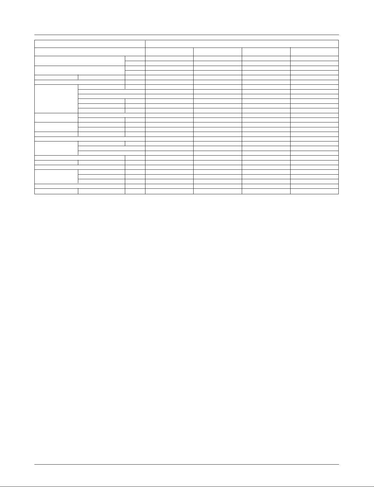
Product Specifications
Rated Cooling Capacity kcal/hr(W)
Btu/hr
Ratedl Heating Capacity kcal/hr(W)
Btu/hr
Air Circulation Indoor(H/M/L)
CMM(CFM)
Setting temperature range °C
Fan motor Output W
Model
No. of Poles
Input W
Running Current A
Capacitor µF/Vac
Fan Type
No. Used / Diameter EA/inch(mm)
Fan RPM Cooling(H/M/L) rpm
Heating(H/M/L) rpm
Noise Level
(Sound Press,1m)
H/M/L dBA
Temperature controller
Coil Tube Size (OD) inch(mm)
Fins per inch
No. of Rows & Column
Dehumidification Rate l/h
Dimensions (W*H*D) Indoor inch(mm)
Net Weight kg(lbs)
Piping Liquid inch(mm)
Connection Gas inch(mm)
Drain hose (ID Ø)mm
Packing Dimension (W*H*D) inch(mm)
Stuffing Quantity
Without(Without) S/Parts 20/40ft
3024(3517) 4536(5274) 6048(7032) 6653(7377)
12000 18000 24000 26400
3478(4044) 5116(5949) 6955(8089) 7635(8880)
13800 20300 27600 30300
10.0/8.3/6.5(353/293/230) 13.5/12/11(477/424/388) 15/13.5/12(530/477/424) 18/16/14(636/564/494)
18~30/16~30 18~30/16~30 18~30/16~30 18~30/16~30
17.5 30 35 42.5
IC-18422LG31A IC-9430LGCG IC-9430LGCE OBM-3019P2
4444
43 53 63 81
0.23 0.23 0.27 0.38
1.5/370 1.5/370 1.5/370 1.5/370
Cross Flow Fan Cross Flow Fan Cross Flow Fan Cross Flow Fan
1/3.7(95) 1/3.1(80) 1/3.1(80) 1/3.1(80)
1240/1120/900 1090/990/890 1160/1060/960 1220/1110/1010
1240/1120/900 1090/990/890 1160/1060/960 1220/1110/1010
40 / 36 / 31 43 / 40 / 37 45 / 42 / 39 45 / 42 / 39
Thermistor Thermistor Thermistor Thermistor
0.197(5.0) 0.275(7.0) 0.275(7.0) 0.275(7.0)
20 18 20 20
2R 12C 2R 12C 2R 14C 2R 14C
1.2 2.3 3.2 3.5
35.4*7.9*19.3 (900*200*490) 47.2*8.1*24.2 (1200*205*615) 47.2*8.1*24.2 (1200*205*615) 47.2*8.1*24.2 (1200*205*615)
12(26.5) 30(66.1) 30(66.1) 30(66.1)
1/4(6.35) 1/4(6.35) 1/4(6.35) 1/4(6.35)
3/8(9.52) 1/2(12.7) 1/2(12.7) 5/8(15.88)
20 20 20 20
38.2*11.2*22.2 (970*285*565) 50.8*11.4*27.4 (1272*290*696) 50.8*11.4*27.4 (1272*290*696) 50.8*11.4*27.4 (1272*290*696)
189/383 102/219 102/219 102/219
Ceiling & Floor (Convertible)
AVNH126ELAC AVNH186BLAC AVNH246BLAC AVNH306BLAC
Indoor Unit Type
Model
Notes:
1. Capacities are based on the following conditions:
Cooling : - Indoor Temperature 27˚C(80.6˚F) DB / 19˚C(66.2˚F) WB
- Outdoor Temperature 35˚C(95˚F) DB / 24˚C(75.2˚F) WB
- Interconnecting Piping Length 7.5m
- Level Difference of Zero.
Heating : - Indoor Temperature 20˚C(68˚F) DB / 15˚C(59˚F) WB
- Outdoor Temperature 7˚C(44.6˚F) DB / 6˚C(42.8˚F) WB
- Interconnecting Piping Length 7.5m
- Level Difference of Zero.
2. Capacities are Net Capacities.
3. Due to our policy of innovation some specifications may be changed without notification.
Page 24
24 Synchro Air Conditioner
Product Specifications
Cooling Capacity kcal/hr(W)
Btu/hr
Heating Capacity kcal/hr(W)
Btu/hr
Input Cooling/Heating W
Running Current Cooling/Heating A
Starting Current Cooling/Heating A
Power Supply Ø,V,Hz
Power Factor %
Number of Connectable Indoor Units
Compressor Locked Rotor Amp. A
Type
Quantity No
Model
Maker
Capacity kcal/hr(Btu/hr)
Motor Type
Motor Input W
Oil Type
Oil Charge cc
O.L.P Type(model name)
Refrigerant Charge * g(oz)
Type
Control
Outdoor Coil Tube Size (OD) inch(mm)
Fins per inch
No. of Rows & Column/No.
Outdoor fan motor Output W
Model
No. Used / No. of Poles
Input W
Running Current A
Capacitor µF/Vac
Outdoor Fan Type
No. Used / Diameter EA/inch(mm)
Discharge Side / Top
Speed rpm
Air Circulation Outdoor CMM(CFM)
Noise Level(Sound Press,1m)
Outdoor dB(A)±1
SVC Valve Liquid inch(mm)
Gas inch(mm)
Dimensions W*H*D inch(mm)
Net Weight Outdoor kg(lbs)
Power Supply Cable No.* mm
2
Connecting Cable No.* mm
2
Max Interunit Total Piping m
Piping Length Total Main Piping m
Total Branch Piping m
For One Room m
Max. Installation Indoor Unit - Outdoor Unit m
Height Difference Indoor Unit - Indoor Unit m
Packing Dimension (W*H*D) inch(mm)
Stuffing Quantity With(Without) S/Parts 20/40ft
12096(14607) 18144(21101) 24192(28135)
48000 72000 96000
13305(15474) 19958(23211) 27820(32355)
52800 79200 110400
5300 / 5050 8000 / 7700 11100 / 11000
10.0 / 9.5 14.7 / 14.4 20 / 19.7
---
3,380~415,50 3,380~415,50 3,380~415,50
82 80 83
Single / Duo / Trio / Quartet Duo / Trio / Quartet Duo / Trio / Quartet
42 at 420V 24 / 27 63 at 420V
Rotary Rotary Scroll
232
GPT330YAA 5JS290PBA21 AR061YAA
LG Matsushita Electric LG
6854(27200) at 50Hz & 380V 6376(25301) at 50Hz & 380V 12625(50100) at 50Hz & 380V
Three Phase Induction Motor Three Phase Induction Motor Three Phase Induction Motor
2550 2680 5330
FVC68D(PVE) FV50S(PVE) FVC68D(PVE)
1200 1130 1800
Internal Type(UBUKATA) IT(Internal Thermostat) Internal Type(UP18TA057)
4200(148.1) 7100(250.4) 7800(275.1)
R-410A R-410A R-410A
L.E.V L.E.V L.E.V
0.276(7.0) 0.276(7.0) 0.276(7.0)
17 17 18
2R 52C
2R 17C + 3R 36C + 2R 17C + 2R 36C 2R 17C + 1R 36C + 2R 17C + 2R 36C
70 271 271
AMR071B9 ARE676E01 ARE676E01
2/6 1/6 2/6
168 429 429
- 1.87 1.87
6/370 10/370 10/370
Propeller Propeller Propeller
2/18.1(460) 1/20.7(526) 2/20.7(526)
Side Discharge Top Discharge Top Discharge
900 850 850
53(1872*2) 90(3179) 185(6533)
56 58 60
3/8 (9.52) 3/8 (9.52) 1/2 (12.7)
3/4 (19.05) 1 (25.4) 1 (25.4)
35.4*45.8*14.5(900*1165*370) 31.5*56.7*27.1(800*1440*690) 50.4*56.7*27.1(1280*1440*690)
105(231) 150(331) 299(659)
5*5.5 (Includes earth) 5*5.5 (Includes earth) 5*5.5 (Includes earth)
4*0.75 (Includes earth) 4*0.75 (Includes earth) 4*0.75 (Includes earth)
110 110 110
50 50 50
60 60 60
15 15 15
30 30 30
111
41.7*48.0*18.3(1060*1220*465) 34.4*61.0*29.7(875*1550*755) 53.1*62.6*29.9(1350*1590*760)
27 / 55 18 / 39 12 / 25
AUUH488C AUUH728C AUUH1008C
Model
Notes:-
1. Capacities are based on the following conditions:
Cooling: - Indoor Temperature 27˚C(80.6ÜV) DB /19˚C(66.2ÜV) WB
- Outdoor Temperature 35˚C(95ÜV) DB /24˚C(75.2ÜV) WB
Heating: - Indoor Temperature 20˚C(68ÜV) DB / 15˚C(59ÜV) WB
- Outdoor Temperature 7˚C(44.6ÜV) DB / 6˚C(42.8ÜV) WB
Piping Length - Interconnecting Pipe Length 7.5m(25ft)
- Level Difference of Zero
2. * : Full factory charge is shipped in the outdoor unit. Chargeless for 30m of piping length.
3. Due to our policy of innovation some specifications may be changed without notification.
Page 25
Service Manual 25
Combination table
Combination table
MPS Variable
AUUH728CAUUH488C
Synchro Combination(k Btu/h) Total(k Btu/h) Branch Kit
Duo(2 Unit)
Trio(3 Unit)
Quartet
(4 Unit)
30 + 36(2:3)
36 + 36(1:1)
18 + 24 + 24(1:2:2)
18 + 18 + 36(1:1:2)
24 + 24 + 24(1:1:1)
24 + 24 + 30(1:1:2)
18 + 18 + 18 + 18
(1:1:1:1)
68
72
66
72
72
78
72
PMUB122A
PMUB112A
PMUB111A
PMUB112A
PMUB1111A
PMUB23A
PMUB11A
Synchro Combination(k Btu/h) Total(k Btu/h) Branch Kit
Single
(1 Unit)
Trio
(3 Unit)
Duo
(2 Unit)
Quartet
(4 Unit)
48
18 + 18 + 18 (1:1:1)
12 + 12 + 12 + 12 (1:1:1:1)
18 + 24 (2:3)
24 + 24 (1:1)
24 + 30 (2:3)
48
54
42
48
54
48
PMUB23A
PMUB11A
PMUB23A
PMUB1111A
PMUB111A
-
AUUH1008C
Synchro Combination(k Btu/h) Total(k Btu/h) Branch Kit
Duo(2 Unit)
Trio(3 Unit)
Quartet
(4 Unit)
36 + 48 (2:3)
36 + 60 (2:3)
48 + 48 (1:1)
24 + 24 + 36(1:1:2)
24 + 24 + 30(1:1:2)
30 + 30 + 30(1:1:1)
30 + 30 + 36(1:1:2)
30 + 36 + 36(1:2:2)
24 + 24 +24 + 24
(1:1:1:1)
84
96
96
84
84
90
96
102
96
PMUB112A
PMUB112A
PMUB111A
PMUB112A
PMUB122A
PMUB1111A
PMUB23A
PMUB23A
PMUB11A
Page 26
26 Synchro Air Conditioner
Installation
Installation
Indoor Unit_Cassette Type
• Please read this instruction sheet completely before installing the product.
• When the power cord is damaged, replacement work shall be performed by authorized personnel only.
• Installation work must be performed in accordance with the national wiring standards by authorized personnel only.
Required Parts Required Tools
• Connecting cable
• Pipes: Gas side
Liquid side
• Hanging Bolt
(W 3/8 or M10 length 650mm)
• Insulated drain hose
• Additional Drain hose
(Inner Diameter...........................32mm)
• Level
• Screw driver
• Electric drill
• Hole core drill (ø70mm)
• Flaring Tools set
• Torque Wrenches
• Hexagonal Wrench (4mm, 5mm)
• Gas-leak detector
• Owner’s Manual
• Thermometer
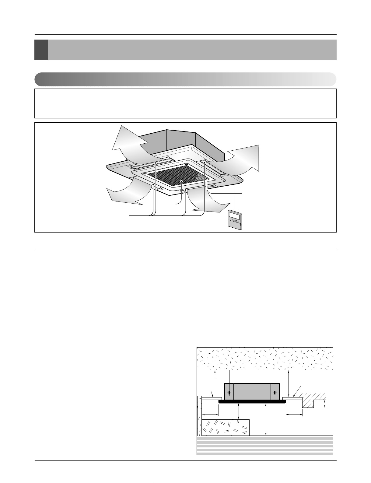
1. Selection of the best location
• There should not be any heat source or steam near the
unit.
• There should not be any obstacles to the air circulation.
• There should be provision of easy condensate drain.
• Taking into accounting the noise prevention criteria,
spot the installation location.
• Do not install the unit near the door way.
• Keep proper distances, of the unit, from ceiling, fence,
floor, walls and other obstacles as shown in figure.
• The indoor unit must have the maintenance space.
Unit:cm
Ceiling
Ceiling Board
Ceiling Board
30 or more
Above 250
400 or less
100
or more
50 or
more
50 or
more
30 or less
Floor
Read completely, than follow step by step.
Anti-bacteria filter
Air
Air Outlet
Intake
Page 27
Service Manual 27
Installation
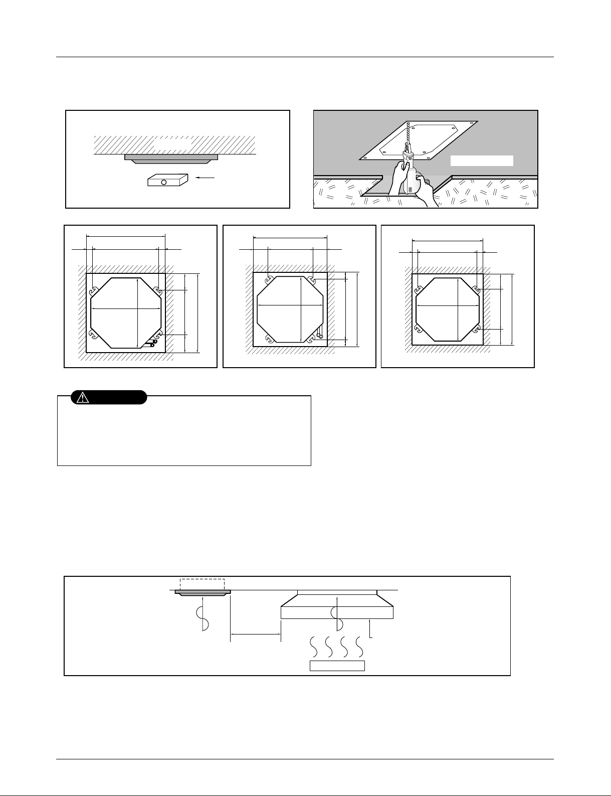
2. Ceiling opening dimensions and hanging bolt location
NOTE:
• Avoid the following installation location.
1. Such places as restaurants and kitchen where considerable amount of oil steam and flour is generated.
These may cause heat exchange efficiency reduction, or water drops, drain pump mal-function.
In these cases, take the following actions;
• Make sure that ventilation fan is enough to cover all noxious gases from this place.
• Ensure enough distance from the cooking room to install the air conditioner in such a place where it may not suck oily steam.
Ceiling board
Level gauge
Ceiling
Unit:mm
570 Unit size
570 Unit size
672 (Hanging bolt)
7575
600 (Ceiling opening)
600 (Ceiling opening)
521(Hanging bolt)
39.5
39.5
TE Model TF Model TD Model
Unit:mm
744 Unit size
744 Unit size
658 (Hanging bolt)
6666
790 (Ceiling opening)
790 (Ceiling opening)
572(Hanging bolt)
109
109
Unit:mm
840 Unit size
840 Unit size
672 (Hanging bolt)
101.5101.5
875 (Ceiling opening)
875 (Ceiling opening)
785(Hanging bolt)
45
45
• The dimensions of the paper pattern for installation are the same as those of the ceiling opening dimensions.
• This air-conditioner uses a drain pump.
• Install the unit horizontally using a level gauge.
• During the installation, care should be taken not to
damage electric wires.
2. Avoid installng air conditioner in such places where cooking oil or iron powder is generated.
3. Avoid places where inflammable gas is generated.
4. Avoid place where noxious gas is generated.
5. Avoid places near high frequency generators.
Use the ventilation fan
for smoke-collecting
hood with sufficient
capacity.
Cooking table
Air conditioner
Take enough
distance
• Select and mark the position for fixing bolts and
piping hole.
• Decide the position for fixing bolts slightly tilted to
the drain direction after considering the direction
of drain hose.
• Drill the hole for anchor bolt on the wall.
CAUTION
Page 28

28 Synchro Air Conditioner
Installation
Set screw of
paper pattern (4 pieces)
Paper pattern
for installation
Ceiling board
150mm
Adjust the same height
Ceiling board
Ceiling
Flat washer for M10
(accessory)
Keep the length of the bolt
from the bracket to 40mm
Open the ceiling board
along the outer edge of the
paper pattern.
Flat washer for M10
(accessory)
Hanging bolt
(W3/8 or M10)
Nut
(W3/8 or M10)
Nut
(W3/8 or M10)
Spring washer
(M10)
Air Conditioner body
• The following parts are local purchasing.
Hanging Bolt - W 3/8 or M10
Nut - W 3/8 or M10
Spring Washer - M10
Plate Washer - M10
• Tighten the nut and bolt to prevent unit from
falling off.
3. Wiring Connection
• Open the control box cover and connect the remote control cord and Indoor power wires.
Make sure that the screws of the terminal are free from looseness.
CAUTION
Indoor
power cord
Remote
controller
cord
Control box cover
Control box cover
fitting screw(2 units)
[Air inlet side view]
Terminal Block in Indoor
1(L) 2(N) 3
WARNING
Connected to outdoor unit
Page 29
Service Manual 29
Installation
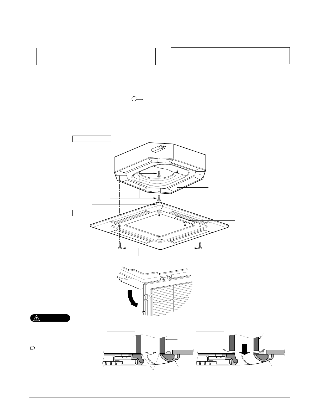
4. Installation of Decoration Panel
1. Temporarily fix two decoration panel fixing screws (hexagon M5 screw) on the unit body. (Tighten by
amount 10mm in length.)
The fixing screws (hexagon M5 screw) are included the indoor unit box.
2. Remove the air inlet grille from the decoration panel. (Remove the hook for the air inlet grille cord.)
3. Hook the decoration panel key hole ( ) on the screws fixed in step above, and slide the panel so
that the screws reach the key hole edge.
4. Retighten completely two temporarily fixed screws and other two screws. (Total 4 screws)
5. Connect the louver motor connector and display connector.
6. After tightening these screws, install the air inlet grille (including the air filter).
Decoration panel fixing screws
(hexagon M5 screws)
Temporally fitting at 2 places
(Tightening about 10mm)
Control box cover
Piping side
Inlet GrilleInlet GrilleInlet Grille
Inlet GrilleInlet Grille
Louver motor
Decoration panel fixing screws
(Hexagon M5 screw)
Air conditioner unit
Decoration panel
Key holes
Display
Lead wire for
louver motor and
display
The decoration panel has its installation
direction.
Before installing the decoration panel,
always remove the paper template.
Install certainly the decoration
panel.
Cool air leakage causes sweating.
Water drops fall.
Air conditioner
unit
Ceiling
board
Decoration panel
Decoration
panel
Fit the insulator (this part) and
be careful for cool air leakage
Good example
Air
Cool air leakage
(no good)
Bad example
Ceiling
board
Air conditioner unit
CAUTION
Page 30
30 Synchro Air Conditioner
Installation
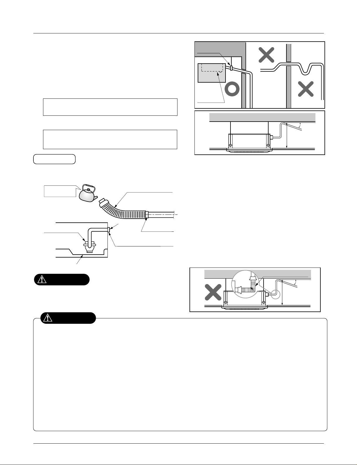
5. Indoor Unit Drain Piping
• Drain piping must have down-slope (1/50 to 1/100): be sure
not to provide up-and-down slope to prevent reversal flow.
• During drain piping connection, be careful not to exert extra
force on the drain port on the indoor unit.
• The outside diameter of the drain connection on the indoor
unit is 32mm.
•
Be sure to install heat insulation on the drain piping.
Piping material: Polyvinyl chloride pipe VP-25
and pipe fittings
The air conditioner uses a drain pump to drain water.
Use the following procedure to test the drain pump operation:
• Connect the main drain pipe to the exterior
and leave it provisionally until the test
comes to an end.
• Feed water to the flexible drain hose and
check the piping for leakage.
• Be sure to check the drain pump for normal
operating and noise when electrical wiring
is complete.
• When the test is complete, connect the
flexible drain hose to the drain port on the
indoor unit.
Heat insulation material: Polyethylene foam with
thickness more than 8 mm.
Drain test
Maintenance
drain port
Upward
routing
not allowed
Pipe clamp
Indoor unit
1/50~1/100
MAX 700mm
Feed water
Drain Pump
Drain pan
Flexible drain hose
(accessory)
Main
drain pipe
Glue the joint
Drain
port
Drain hose connection
Use the clip (accessory)
CAUTION
The supplied flexible drain hose should not be curved,
neither screwed. The curved or screwed hose may
cause a leakage of water.
1/50~1/100
MAX 700mm
Flexible drain hoseFlexible drain hose
After the confirmation of the above conditions, prepare the wiring as follows:
1) Never fail to have an individual power specialized for the air conditioner. As for the method of wiring, be guided by the
circuit diagram pasted on the inside of control box cover.
2) Provide a circuit breaker switch between power source and the unit.
3) The screw which fasten the wiring in the casing of electrical fittings are liable to come loose from vibrations to which the
unit is subjected during the course of transportation. Check them and make sure that they are all tightly fastened. (If they
are loose, it could give rise to burn-out of the wires.)
4) Specification of power source
5) Confirm that electrical capacity is sufficient.
6) Be sure that the starting voltage is maintained at more than 90 percent of the rated voltage marked on the name plate.
7) Confirm that the cable thickness is as specified in the power sources specification.
(Particularly note the relation between cable length and thickness.)
8) Never fail to equip a leakage breaker where it is wet or moist.
9) The following troubles would be caused by voltage drop-down.
• Vibration of a magnetic switch, damage on the contact point there of, fuse breaking, disturbance to the normal function of a
overload protection device.
• Proper starting power is not given to the compressor.
CAUTION
Page 31

Service Manual 31
Installation
6. Accessories
Name
Quantity
Shape
for gas pipe
for liquid pipe
Clamp metal
1 EA
Insulation for
fitting
1 SET
Drain hose
1 EA
Clamp
8 EA
Washer for
hanging backet
8 EA
(Other)
Optional Accessories(For Unit)
Standard Accessories
• Paper pattern for
installation
• Owner's manual
• Installation manual
No. Item Type Model No.
Component Parts
• Wireless remote control : 1EA
• Holder : 1EA
• Battery : 2EA
• Screw : 2EA
• Simple central controller
• Manual
• Deluxe central controller
• Manual
• Program CD
• Hard lock key, Manual
• PCB & Wire assembly
• Installation manual
(For all central control)
• PCB & Wire assembly
(For Deluxe, PC Based central
control)
• Front panel assembly
• Remote controller
• Manual
1
2
3
4
Wireless remote
control
With air purifying
function
AHWRHD
Central control
Simple
Deluxe
PC Based
PQCSA101S0
PQCSW501A0
PQCSW502A0
PQCSS501A0
PQCSS502A0
Gateway
PI485
CNU
PHNFP14A0
PQNFG00A0
Elevation Grille
Kit
Decoration
panel
PT-HEF
PT-HFF
PT-HDF
Page 32

32 Synchro Air Conditioner
Installation
Ceiling & Floor(Convertible) Type
• Please read this instruction sheet completely before installing the product.
• When the power cord is damaged, replacement work shall be performed by authorized personnel only.
• Installation work must be performed in accordance with the national wiring standards by authorized personnel only.
Required Parts Required Tools
• Installation Plate
• Four Type “A” screws
• Connecting cable
• Level
• Screw driver
• Electric drill
• Hole core drill (ø70mm)
• Pipes: Gas side ..........Ø9.52, Ø12.7, Ø15.88mm
Liquid side.............................................Ø6.35mm
• Insulated drain hose
• Insulation materials
• Flaring Tools set
• Specified Torque Wrenches
1.8kg·m...........................Liquid side piping
5.5kg·m .............................Gas side piping
Spanner .....................................Half union
• Specified Torque Wrenches
1.8kg·m...........................Liquid side piping
5.5kg·m..............................Gas side piping
• Hexagonal Wrench (4mm)
• Gas-leak Detector
• Two type “B” screws • Owner’s Manual
• Thermometer
Installation Plate (VB, 2pcs)
-1 Installation Plate (VE, 1pc)
Washer Bolt (M8 L25, 4pcs, type "A")
Floor Mount Bracket (1pcs)
Drain Hose, Insulated
Drain Hose Hanger and screw
Suspension Bolt
Bolts for Mount Bracket
Connecting Tube(mm)
• Gas side : Ø12.7, Ø15.88
• Liquid side : Ø6.35
Connecting Cable
Drain Hose Extended
Installation Parts Provided
The other Installation Parts Needed
1-1
6
5
(Floor Mounting)
(Ceiling/Wall Mounting)
7
1
2
3
4
Page 33

Service Manual 33
Installation
1. Selection of the best location
• There should not be any heat source or steam near the
unit.
• There should not be any obstacles to the air circulation.
• There should be provision of easy condensate drain.
• Taking into accounting the noise prevention criteria, spot
the installation location.
• Do not install the unit near the door way.
• Keep proper distances, of the unit, from ceiling, fence,
floor, walls and other obstacles as shown in figure.
• The indoor unit must have the maintenance space.
More than
20cm
More than eye-level
More than
20cm
R
R
More than
20cm
More than
20cm
(Ceiling installation)
(Floor/Wall installation)
2. Wiring connection
1) Connecting cables to the Indoor Unit
1. Remove the Air guide - L by loosening 2 screws after
removing the Inlet grille from the Indoor unit.
2. Connect the wires to the terminals on the control board
individually according to the outdoor unit connection.
• Ensure that the color of the wires of outdoor unit and
the terminal No. are the same as those of indoor unit
respectively
AIR GUIDE-L
INDOOR UNIT
Control
Panel
1
2
Clamp
Terminal Block in Indoor
1(L) 2(N) 3 4
Connected to outdoor unit
2) Clamping of cables
1) Arrange 2 power cables on the control panel.
2) First, fasten the steel clamp with a screw to the inner boss of control panel.
3) For the cooling model, fix the other side of the clamp with a screw strongly.
For the heat pump model, put the 0.75mm2cable(thinner cable) on the clamp and tighten it with a plastic clamp to the
other boss of the control panel.
4) In Australia, the length of power supply cord measured from the entry of the power supply cord to the middle of live pin
on the power plug should be over 1.8m.
R
Page 34

34 Synchro Air Conditioner
Installation
Drain hose
Ceiling
Ceiling
Ceiling
CAUTION
Front of view
Side of view
1. Install declination of the indoor unit is very important for the drain of the convertible type air
conditioner.
2. Minimum thickness of the insulation for the connecting pipe shall be 7mm.
3. If the Installation Plates are fixed to horizontal line, the indoor unit after installing will be declined
to the bottomside.
• The unit must be horizontal or declined to the drain hose connected when finished installation.
• The unit must be declined to the bottomside of the unit when finished installation.
Page 35

Service Manual 35
Installation
After the confirmation of the above conditions, prepare the wiring as follows:
1) Never fail to have an individual power specially for the air conditioner. As for the method of
wiring, be guided by the circuit diagram pasted on the inside of control box cover.
2) Provide a circuit breaker switch between power source and the unit.
3) The screw which fasten the wiring in the casing of electrical fittings are liable to loose due to
vibrations to which the unit is subjected during the course of transportation. Check them and
make sure that they are all tightly fastened. (If they are loose, it could give rise to burn-out of the
wires.)
4) Specification of power source
5) Confirm that electrical capacity is sufficient.
6) Be sure that the starting voltage is maintained at more than 90 percent of the rated voltage
marked on the name plate.
7) Confirm that the cable thickness is as specified in the power sources specification.
(Particularly note the relation between cable length and thickness.)
8) Never fail to equip a leakage breaker where it is wet or moist.
9) The following troubles would be caused by voltage drop-down.
• Vibration of a magnetic switch, damage on the contact point there of, fuse breaking, disturbance to
the normal function of a overload protection device.
• Proper starting power is not given to the compressor.
10) The means for disconnection from a power supply shall be incorporated in the fixed wiring and
have an air gap contact separation of at least 3mm in each active(phase) conductors.
CAUTION
Page 36

36 Synchro Air Conditioner
Installation
3. Accessories
Name
Quantity
Shape
for gas pipe
for liquid pipe
Clamp metal
1 EA
Insulation for
fitting
1 set
Drain hose
1 EA
Clamp
8 EA
Washer for
hanging backet
6 EA
(Other)
• Owner's manual
• Installation manual
Optional Accessories(For Unit)
Standard Accessories
No. Item Type Model No.
Component Parts
• Simple central controller
• Manual
• Deluxe central controller
• Manual
• Program CD
• Hard lock key, Manual
• PCB & Wire assembly
• Installation manual
(For all central control)
• PCB & Wire assembly
(For Deluxe, PC Based central
control)
1
2
Central control
Simple
Deluxe
PC Based
PQCSA101S0
PQCSW501A0
PQCSW502A0
PQCSS501A0
PQCSS502A0
Gateway
PI485
CNU
PHNFP14A0
PQNFG00A0
Page 37

Service Manual 37
Installation
Ceiling Concealed Duct Type
• Please read this instruction sheet completely before installing the product.
• When the power cord is damaged, replacement work shall be performed by authorized personnel only.
• Installation work must be performed in accordance with the national wiring standards by authorized personnel only.
Required Parts Required Tools
• Connecting cable
• Pipes: Gas side
Liquid side
• Hanging Bolt
(W 3/8 or M10 length 650mm)
• Insulated drain hose
• Additional Drain hose
(Outer Dia ................................25.4mm)
• Level
• Screw driver
• Electric drill
• Hole core drill (ø70mm)
• Flaring Tools set
• Torque Wrenches
• Hexagonal Wrench (4mm, 5mm)
• Gas-leak detector
• Owner’s Manual
• Thermometer
1. Selection of the best location
Install the air conditioner in the location that satisfies the following conditions.
• The place shall easily bear a load exceeding four times the
indoor unit’s weight.
• The place should have enough area for inspection as shown
in figure.
• The place where the unit shall be leveled.
• The place shall allow easy water drainage.(Suitable dimen-
sion “H” is necessary to get a slope to drain as figure.)
• The place shall easily connect with the outdoor unit.
• The place where the unit is not affected by an electrical
noise.
• The place where air circulation in the room will be good .
• There should not be any heat source or steam near the unit.
Top view
(unit: mm)
H
Front view
600600
Front
Inspection hole
(600X600)
Control box
1000
Air outlet vents
Air filters
Air intake vents
Wired LCD Remote Control
Page 38

38 Synchro Air Conditioner
Installation
2. Ceiling dimension and hanging bolt
location
■ Installation of Unit
Install the unit above the ceiling correctly.
• Apply a joint-canvas between the unit and duct to absorb
unnecessary vibration.
• Apply a filter Accessory at air return hole.
• Refer toDimensinal Drawings.
• Install the unit leaning to a drainage hole side as a figure
for easy water drainage.
• A place where the unit will be leveled and that can support the weight of the unit.
• A place where the unit can withstand its vibration.
• A place where service can be easily performed.
CASE 1
POSITION OF SUSPENSION BOLT
CASE 2
POSITION OF CONSOLE BOLT
Drainage hole
M10 Nut
M10 SP. washer
M10 washer
X 4
X 4
(Local
supply)
X 4
M10 Nut
M10 SP. washer
M10 washer
X 4
X 4
(Local
supply)
X 4
A
B
C
1-3 mm
D
(G)
H
I
EF
NOTE:
• Throughly study the following installation locations:
1. In such places as restaurants and kitchens, considerable amount of oil steam and flour adhere to the fan, the fin of the heat
exchanger, resulting in heat exchange reduction, spraying, dispersing of water drops, etc.
In these cases, take the following actions:
• Make sure that the ventilation fan for smoke-collecting hood on a cooking table has sufficient capacity so that it draws oily
steam which should not flow into the suction of the air conditioner.
• Make enough distance from a cooking room to install the air conditioner in such a place where it may not suck in oil steam.
2. Avoid installing air conditioner in such circumstances where cutting oil mist or iron powder is in suspension in factories, etc.
3. Avoid places where inflammable gas is generated, flows in, is stored or vented.
4. Avoid places where sulfurous acid gas or corrosive gas is generated.
5. Avoid places near high frequency generators.
Page 39

Service Manual 39
Installation
• Select and mark the position for fixing bolts.
• Drill the hole for set anchor on the face of ceiling.
• Insert the set anchor and washer onto the suspen-
sion bolts for locking the suspension bolts on the
ceiling.
• Mount the suspension bolts to the set anchor firmly.
• Secure the installation plates onto the suspension
bolts (adjust level roughly) using nuts, washers and
spring washers.
Tighten the nut and bolt to prevent unit falling.
3. Connecting Cables
Connect the wires to the terminals on the control board individually according to the outdoor unit connection.
• Ensure that the color of the wires of outdoor unit and the terminal No. are the same as those of indoor unit respectively
Clamping of cables
1) Arrange 2 power cables on the control panel.
2) First, fasten the steel clamp with a screw to the inner boss of control panel.
3) For the cooling model, fix the other side of the clamp with a screw strongly. For the heat pump model, put the
0.75mm2 cable(thinner cable) on the clamp and tighten it with a plastic clamp to the other boss of the control
panel.
4) In Australia, the length of power supply cord measured from the entry of the power supply cord to the middle
of
live pin on the power plug should be over 1.8m.
Make sure that the screws of the terminal are free from looseness.
WARNING
Terminal Block in Indoor
1(L) 2(N) 3 4
Connected to outdoor unit
CAUTION
Old building New building
1 Set anchor
2 Plate washer
3 Spring washer
4 Nut
5 Suspension
bolts
Page 40

40 Synchro Air Conditioner
Installation
All thermal insulation must comply with local requirement.
INDOOR UNIT
THERMAL INSULATION
Make sure that there is no clearance here.
Overlap with thermal
insulator for piping.
Thermal insulator for refrigerant pipe
(Local supply)
Thermal insulator for
piping(Local supply)
Hose crip for thermal insulator(Local supply)
Union for liquid pipe
Refrigerant pipe and thermal
insulator(Local supply)
Union for gas pipe
Thermal insulator for refrigerant pipe
(Local supply)
Hose crip for thermal insulator
(Local supply)
5. Checking the Drainage
1. Remove the Air Filter.
2. Check the drainage.
• Spray one or two glasses of water on the evaporator.
• Ensure that water flows to drain hose from indoor
unit without any leakage.
4. Insulation
Page 41

Service Manual 41
Installation
Ceiling
CAUTION
1~3mm
Drainage hole
Drainage hole
U-Trap
B
C
A ≥ 70mm
B ≥ 2C
C ≥ 2 x SP
SP = External Pressure
(mmAq)
Ex) External Pressure
= 10mmAq
A ≥ 70mm
B ≥ 40mm
C ≥ 20mm
A
Make sure to be closed.
Unit
Drainage pipe
(Local supply)
Thermal insulator
(Local supply)
Drainage hole
CAUTION FOR GRADIENT OF
UNIT AND DRAIN PIPING
Lay the drain hose with a downware
inclination so water will drain out.
MAX 700mm
Drain Pipe
Drain Pump
1/50~1/1001/50~1/100
Front of view
• Alway lay the drain with downward inclination
(1/50 to 1/100).
Prevent any upward flow or reverse flow in any
part.
• 5mm or thicker formed thermal insulator shall
always be provided for the drain pipe.
CORRECT
• Install the P-Trap (or U-Trap) to prevent
a water leakage caused by the blocking
of intake air filter.
Applied U-Trap Dimension
1. Decline Installation of indoor unit is very important for the drain of the duct type air conditioner.
2. Minimum thickness of the insulation for the connecting pipe should be 5mm.
• The unit must be or declined to wards drain hose while installation.
CORRECT
INCORRECT
INCORRECT
Page 42

42 Synchro Air Conditioner
Installation
6. Accessories
Name
Quantity
Shape
for gas pipe
for liquid pipe
Clamp metal
1 EA
Insulation for
fitting
1 set 1 set
Drain hose
1 EA
(Other)
Clamp
6 EA
Screws for
duct flanges
• Owner's manual
• Installation manual
• Washers(8 pcs.)
Optional Accessories(For Unit)
Standard Accessories
No. Item Type Model No.
Component Parts
• Wireless remote control : 1EA
• Holder : 1EA
• Battery : 2EA
• Screw : 2EA
• Plasm air purifier kit: 1EA
• Wired remote control: 1EA
• Factory sypplied-zone control PCB
• Durchased locally-damper,
Damper moter, thermostat
• Drain Pump Assembly: 1EA
• Simple central controller
• Manual
• Deluxe central controller
• Manual
• Program CD
• Hard lock key, Manual
• PCB & Wire assembly
• Installation manual
(For all central control)
• PCB & Wire assembly
(For Deluxe, PC Based
central control)
1
2
3
4
5
6
Wireless remote
control
With air purifying
function
AHWRHS
AHWRHD(LCD)
Plasma air puirifying
filter
-
ABPAHH
ABPAGH
ABPARH
Zone Control - ABZCA
Drain Pump - ABDPG
Central Control
Simple
Deluxe
PC Based
PQCSA101S0
PQCSW501A0
PQCSW502A0
PQCSS501A0
PQCSS502A0
Gateway
PI485
CNU
PSNFP14A0
PQNFG00A0
Page 43

Service Manual 43
Installation
Connecting Pipes to the Indoor Unit
Main cause of gas leakage is defect in flaring work.
Carry out correct flaring work in the following procedure.
1. Cut the pipes and the cable.
• Use the accessory piping kit or the pipes purchased locally.
• Measure the distance between the indoor and the
outdoor unit.
• Cut the pipes a little longer than measured distance.
•
Cut the cable 1.5m longer than the pipe length.
2. Burrs removal
• Completely remove all burrs from the cut cross
section of pipe/tube.
•
Put the end of the copper tube/pipe to downward
direction as you remov e b urrs in order to a void to let
burrs drop in the tubing.
3. Putting nut on
• Remove flare nuts attached to indoor and outdoor
units, than put them on pipe/tube having completed burr removal.
(Not possible to put them on after flaring work)
4. Flaring work
•
Carry out flaring work using dedicated flaring tool
for R-410A as shown below.
Firmly hold copper tube in a bar(or die) as indicated
dimension in the table above.
5. Check
• Compare the flared work with figure below.
• If flare is noted to be defective, cut off the flared
section and do flaring work again.
Copper
tube
90°
Slanted Uneven Rough
Pipe
Reamer
Point down
Flare nut
Copper tube
Bar
Copper pipe
Clamp handle
Red arrow mark
Cone
Yoke
Handle
Bar
"A"
Inclined
Inside is shining without scratches
Smooth all round
Even length
all round
Surface
damaged
Cracked Uneven
thickness
= Improper flaring =
Outside diameter A
mm inch mm
Ø6.35 1/4 0~0.5
Ø9.52 3/8 0~0.5
Ø12.7 1/2 0~0.5
Ø15.88 5/8 0~1.0
Ø19.05 3/4 0~1.0
■ Preparation of Piping
Page 44

44 Synchro Air Conditioner
Installation
Remote Controller
Remote Controller Preparation (Convertible type)
Remote control
box body
Cord clamp
(accessory)
Lever carefully
the box open
using a screw
driver, etc.
Front case
The lower part
Face of wall
Under plate
Screw (accessory)
HOW TO MOUNT ONTO A WALL
HOW TO INSERT BATTERIES
1. Remove the battery cover from the remote controller.
• Slide the cover according to the arrow direction.
2. Insert the two batteries.
• Be sure that the (+) and (-) directions are correct.
• Be sure that both batteries are new.
3. Re-attach the cover.
• Slide it back into position.
• Fix the under plate on the wall
• Separate the under plate from Remote control box.
• Fix the cord clamps on the wall by
ø 3 tapping screws (accessory).
• Fix the remote control cord.
DISASSEMBLING
ELECTRICAL WIRING
Wire and make sure that terminal
numbers are matched on unit side and
remote controller side.
The maximum length of the cord is 100m.
If the length of the cord exceeds 50m,
use a wire size greater than 0.5mm
2
.
(Main board)
CN REMO
• Do not use rechargeable batteries, such batteries differ
from standard dry cells in
shape, dimensions, and performance.
• Romove the batteries from the
remote controller if the air conditioner is not going to be used
for some long time.
Page 45

Service Manual 45
Installation
Outdoor Unit_AUUH728C
1. Selection of the best location
• If an awning is built over the unit to prevent direct sunlight or rain exposure, make sure that heat radiation from the condenser is not restricted.
• Do not place animals and plants in the path of the warm air.
• Take the air conditioner weight into account and select a place where noise and vibration are minimum.
• Select a place so that the warm air and noise from the air conditioner do not disturb neighbors.
• Rooftop Installations : If the outdoor unit is installed on a roof structure, be sure to level the unit. Ensure
the roof structure and anchoring method are adequate for the unit location. Consult local codes regarding rooftop mounting.
2. Individual installation
Basic Space required
• A space of at least 250 mm is nessary at the back for inlet air. Tacking servicing, a space of about 750 mm
should be provided at the front.
A : 750 mm or more
B : 250 mm or more
C : Top discharge(open in principle)
D : Front inlet(open in principle)
E : Rear inlet(open in principle)
<Side View>
<Top View>
D
C
B
A
E
service space
Front
Rear
Page 46

46 Synchro Air Conditioner
Installation
A : 750 mm or more
B : 250 mm or more
When inlet air enters from right and left sides of unit
Rear
Front
A : 750 mm or more
B : 250 mm or more
C : 150 mm or more
<Top View> <Side View>
When unit is surrounded by walls
When there is an obstructure above the unit
A : 45˚ or more
B : 200 mm or more
C : 250 mm or more
D : 1000 mm or more
E : Air outlet guide (procured at the site)
F : 250 mm or more
C
A
B
C
A
B
A
B
B
B
A
B
C
E
D
F
Page 47

Service Manual 47
Installation
• Space required for collective installation and continuous installation : When installing several
units, leave the space between each block as show below considering passage for air and people.
A : Open state
B : 750 mm or more
C : 250 mm or more
D : 250 mm or more
Front
Rear
Rear
Front
3. Collective installation and continuous installation
Page 48

48 Synchro Air Conditioner
Installation
Outdoor Unit_AUUH1008C
1. Individual installation
Basic Space required
• A space of at least 250 mm is nessary at the back for inlet air. Tacking servicing, a space of about 750 mm
should be provided at the front.
<Top View><Side View>
A : 750 mm or more
B : 250 mm or more
C : Top discharge(open in principle)
D : Front inlet(open in principle)
E : Rear inlet(open in principle)
D
C
B
A
E
service space
Front
Rear
A : 750 mm or more
B : 250 mm or more
When inlet air enters from right and left sides of unit
Rear
Front
A : 750 mm or more
B : 250 mm or more
C : 150 mm or more
<Top View> <Side View>
When unit is surrounded by walls
C
A
B
C
A
B
A
B
B
B
Page 49

Service Manual 49
Installation
• Space required for collective installation and continuous installation : When installing several
units, leave the space between each block as show below considering passage for air and people.
A : Open state
B : 750 mm or more
C : 250 mm or more
D : 250 mm or more
Front
Rear
Rear
Front
When there is an obstructure above the unit
A : 45˚ or more
B : 200 mm or more
C : 250 mm or more
D : 1000 mm or more
E : Air outlet guide (procured at the site)
F : 250 mm or more
A
B
C
E
D
F
2. Collective installation and continuous installation
Page 50

50 Synchro Air Conditioner
Installation
• Anchor the outdoor unit with a bolt and nut(ø10mm) tightly and horizontally on a concrete or rigid mount.
• When installing on the wall, roof or rooftop, anchor the mounting base securely with a nail or wire assuming
the influence of wind and earthquake.
• In the case when the vibration of the unit is conveyed to the hose, secure the unit with an anti-vibration rubber.
A
UUH1008C
AUUH728C
Settlement of outdoor unit
500
• Example of collectiv
500±2
Installation foot
e installation
250
556
• Individual installation
700±2
500±2500±2
250
556
500±2
900
• Example of collectiv
900±2
Installation foot
e installation
250
556
• Individual installation
700±2
900±2 900±2
250
556
900±2
Page 51

Service Manual 51
Installation
Lifting Method
• When carrying the unit suspended, pass the ropes under the unit and use the two suspension points each at
the front and rear.
• Always lift the unit with ropes attached at four points so that impact is not applied to the unit.
• Attach the ropes to the unit at an angle of 40° or less.
• Use two ropes at least 7 m long.
Caution:
Be very careful to carry product.
• Do not have only one person carry product if it is more than 20 kg.
• PP bands are used to pack some products. Do not use them as a mean for transportation because they are
dangerous.
• Do not touch heat exchanger fins with your bare hands. Otherwise you may get a cut in your hands.
• Tear plastic packaging bag and scrap it so that children cannot play with it. Otherwise plastic packaging
bag may suffocate children to death.
• When carrying in outdoor unit, be sure to support it at four points. Carrying in and lifting with 3-point support
may make outdoor unit unstable, resulting in a fall of it.
A
A
40° or less
Rope suspension part
B
40° or less
Rope suspension part
B
Page 52

52 Synchro Air Conditioner
Installation
Branch
Main (L1)
h1
b
L2
L3
L4
L5
h2
Branch
Main (L1)
h1
b
L2
L3
L4
L5
h2
L1
L2
L3
L4
L5
Outdoor
Unit
Indoor Unit
Piping length and the elevation
Install the branch pipe so that pipe length and difference between high and low will not exceed below SPEC.
AUUH728C
AUUH488C
AUUH1008C
• When installing the branch pipe, direction and angle of installation is not limited.
• Take care so that burrs and foreign material may not enter into the cutting surface when connecting.
• Don’t use the liquid pipe by too bending or twisting.
Pipe Length(m)
Total(Main+Branch)
Main Pipe(L1)
Branch Pipe----Total
Each
In out (h1)
In-In (h2)
L1+L2/L3/L4/L5
Indoor-Indoor_(b)
Spec.
110
50
60
15
30
1
65
10
Page 53

Service Manual 53
Installation
1. Form the piping according to its routing. Avoid bending and bending back the same piping point more than
three times. (This will result in hardening the pipe.)
2. After deforming the piping, align centers of the union fitting of the indoor unit and the piping, and tighten them
firmly with wrenches.
3. Connect pipe to the service valve or ball valve which is located below the outdoor unit.
4. After completing the piping connection, be sure to check if there is gas leakage in indoor and outdoor connection.
AUUH7280
AUUH10080
Elbow
Welding
Elbow
Elbow
Welding
Welding
AUUW4860AUUW6060
Elbow
Piping Connection
Page 54

54 Synchro Air Conditioner
Installation
2. AUUH728C/AUUH1008C
For additional charging method, see below table.
❈ Note: If total additional charge value after calculation comes out to be negative, then do not consider additional
charge.
CAUTION:
• Rated performance for refrigerant line length of:7.5m
• Capacity is based on standard length and maximum allowance length is on the basis of
reliability.
• Improper refrigerant charge may result in abnormal cycle.
• Oil trap should be installed every 10 meters.
(L1=Main Pipe, L2~L5 : Branch Pipe)
1. AUUH488C
There is not additional charging of refrigerant by main pipe of 30m below.
For additional charging method, see below table.
❈ Note: If total additional charge value after calculation comes out to be negative, then do not consider additional
charge.
CAUTION:
• Rated performance for refrigerant line length of:7.5m
• Capacity is based on standard length and maximum allowance length is on the basis of
reliability.
• Improper refrigerant charge may result in abnormal cycle.
• Oil trap should be installed every 10 meters.
(L1=Main Pipe, L2~L5 : Branch Pipe)
Refrigerant Additional Charging Method
Synchro Refrigerant Additional charging (kg)
Duo
Trio
Quartet
Refrigerant = (L1-30) x A + (L2+L3-20) x 0.03
Refrigerant = (L1-30) x A + (L2+L3+L4-20) x 0.03
Refrigerant = (L1-30)
x A +
(L2+L3+L4+L5-20)
x
Model
AUUH488C
0.03
A
0.07
Synchro Refrigerant Additional charging (kg)
Duo
Trio
Quartet
Refrigerant = (L1 - 5) x 0.05 + (L2 + L3 - 20) x A
Refrigerant = (L1 - 5) x 0.05 + (L2 + L3 + L4 - 20) x A
Refrigerant = (L1 - 5)
x
0.05 + (L2 + L3 + L4 + L5 - 20)
x
Refrigerant Branch
A
Pipe (mm)
Ø 6.35
Ø 9.52
A
0.03 kg/m
0.05 kg/m
Page 55

Service Manual 55
Installation
Branch Kit
1. Type of branch pipe
Separately use a branch pipe depending on indoor capacity for installation.
Unbalance type of branch pipe must be connected depending on large capacity or small capacity.
2. Accessory for Installation
3. SPEC for branch pipe connection part
• Procure other parts than those specified in this manual in the scene
• No.
parts are used for connection of 48/60k indoor unit.
Indoor Classification
2 UNIT
3 UNIT
4 UNIT
Model Name
PMUB11A
PMUB23A
PMUB122A
PMUB112A
PMUB111A
PMUB1111A
Capacity Ratio(%)
50:50 (1:1)
40:60 (2:3)
20:40:40 (1:2:2)
25:25:50 (1:1:2)
33:33:33 (1:1:1)
25:25:25:25(1:1:1:1)
Remark
Unbalance type
Unbalance type
Unbalance type
Manual Gas pipe Liquid pipe Insulation(Gas pipe) Insulation(Liquid pipe)
Insulation Band Socket
(I.D)
Ø19.05(3/4) Ø25.4(1)
Ø9.52(3/8) Ø12.7(1/2)
Ø12.7(1/2) Ø15.88(5/8)
Ø6.35(1/4) Ø9.52(3/8)
Ø9.52(3/8) Ø12.7(1/2)
a
b
B
A
D
C
(Ø15.88→Ø19.05)
(Gas pipe)
(Liquid pipe)
(): inch
Page 56

56 Synchro Air Conditioner
Installation
4 .Thermal insulation work
• Securely wrap the refrigerant and the branch pipe by using thermal insulation materials provided.
When using thermal insulation materials released, use withstand heat insulation materials
(thickness of more than 15mm).
• Securely adhere thermal insulation materials
wrapping the branch pipe so that they do not
widen.
After wrapping them with auxiliary materials
, bound them with a band .
• Finish the work by wrapping with a vinyl tape after the insulation material work.
Band 7
Vinyl Tape
Insulation
4
Band 7
Insulation
6
Insulation
Vinyl Tape
Vinyl Tape
Insulation
Band 7
5
6
Page 57

Service Manual 57
Installation
Wiring Connection
1. All wiring must comply with LOCAL REGULATIONS.
2. Select a power source that is capable of supplying the current as required by the air conditioner.
3. Feed the power source to the unit via a distribution switch board designed for this purpose.
4. The terminal screws inside the control box may be loose due to vibration during transport.
Check the screws for loose connection.
(Running the air conditioner with loose connection can overload and damage electrical components.)
5. Always ground the air conditioner with a grounding wire and connector to meet the LOCAL REGULATION.
The power cord connected to the outdoor unit should be
complied with the following specifications (Rubber
insulation, type H05RN-F approved by HAR or SAA).
If the supply cord is damaged, it must be replaced by a special cord or assembly available from the manufacturer of its service agent.
The connecting cable connected to the indoor and outdoor
unit should be complied with the following specifications
(Rubber insulation, type H05RN-F approved by HAR or SAA).
CAUTION
20mm
GN/YL
NORMAL
CROSS-SECTIONAL
AREA 1.25mm
2
NORMAL
CROSS-SECTIONAL
AREA 5.5mm
2
20mm
GN/YL
Terminal Block
(Outdoor Unit)
Terminal Block
(Indoor Unit)
RSTN
Power
Input
WARNING:
Make sure that the screws of the terminal are free from looseness.
AUUH488C/AUUH728C/AUUH1008C
Page 58

58 Synchro Air Conditioner
Installation
Auto addressing
Auto addressing work should be done for simultaneous operation.
Addressing work assigns address to each Indoor Unit.
When firstly installing product or replacing the Indoor Unit PCB.
3. Auto Addressing Method
Table.a ZONE SW1 Setting
TEST_SW1
LED01T
JIG_SW
1234
ZONE SW1
Main PCB
Fig.a Outdoor PCB diagram
C
B
A
1. JIG_SW Setting
Check the JIG_SW to the right, or not set the JIG_SW to
the right.( A )
2. ZONE SW1 Setting
Set the ZONE SW1 as below Table.a ( B )
❈ S/W1 is not used.
❈ 1 means S/W up.
0 means S/W down.
* Work procedure
1) Set JIG_SW and ZONE SW1 correctly.
2) Turn on main power.
3) Press the TEST_SW1 for about 3 seconds within 3minutes After
main power on.( C )
4) After step 3), the LED01T(green LED) rapidly flickers.
When Addressing work is done, green LED is off, else LED stops
flickering and lights continuously.
5) If you fail to perform the Addressing work,
repeat step 2),3).
AUUH488C/AUUH728C/AUUH1008C
ZONE SW1
Indoor Unit No.
12
34
x0
00
x1
00
x
1
10
2(Duo)
1(Single)
3(Trio)
4(Quartet)
12
3
4
12
3
4
x
1
11
12
3
4
Page 59

Service Manual 59
Installation
How to simultaneous operating
- Keep the following procedure when simultaneously operating two units or more cassette type, duct type, and
convertible type of indoor units via the free joint.
1. Turn on the power of the unit by the installed remote controller, a wire or a
wireless remote controller. When an installation professional installs it,
only one wire remote controller is installed except the location with only the
Convertible combination installed (using the wireless remote controller)
when completing the indoor unit setting (Cassette ceiling top/bottom, Duct
E.S.P. value).
2. After setting the desired operation mode and temperature and then starting
the unit to operate, wait for 2 or 3 seconds.
3. The remaining unites simultaneously starts with the same setting mode to
operate.
4. If you want to stop operating, the remaining units are operated to stop in 2
or 3 seconds by the installed remote controller. (However, the location with
only the Convertible combination is operated by the wireless remote controller.)
5. For more information about how to operate the remote controller, refer to
the previous pages.
R
R
Page 60

60 Synchro Air Conditioner
Installation
Test running
1. PRECAUTIONS IN TEST RUNNING
• The initial power supply must provide at least 90% of the rated voltage.
Otherwise, the air conditioner should not be operated.
CAUTION For test run, carry out the cooling operation firstly even during heating season. If
heating operation is carried out firstly, it leads to the trouble of compressor. Then
attention must be paid.
Carry out the test run more than 5 minutes without fail.
(Test run will be cancelled 18 minutes later automatically)
• The test run is started by pressing the room temperature checking button and down timer button for 3 seconds at the same time.
• To cancel the test run, press any button.
CHECK THE FOLLOWING ITEMS WHEN INSTALLATION IS COMPLETE
• After completing work, be sure to measure and record trial run properties, and store measured data, etc.
• Measuring items are room temperature, outside temperature, suction temperature, blow out temperature, wind
velocity, wind volume, voltage, current, presence of abnormal vibration and noise, operating pressure, piping
temperature, compressive pressure.
• As to the structure and appearance, check following items.
2. Connection of power supply
1. Connect the power supply cord to the independent power supply.
• Circuit breaker is required.
2. Operate the unit for fifteen minutes or more.
3. Evaluation of the performance
1. Measure the temperature of the intake and discharge air.
2. Ensure the difference between the intake temperature and the discharge one is more than 8°C
(Cooling) or reversely (Heating).
Is the circulation of air adequate?
Is the draining smooth?
Is the heat insulation complete
(refrigerant and drain piping)?
Is there any leakage of refrigerant?
Is the remote controller switch operated?
Is there any faulty wiring?
Are not terminal screws loosened?
M4......118N.cm{12kgf.cm} M5......196N.cm{20kgf.cm}
M6......245N.cm{25kgf.cm} M8......588N.cm{60kgf.cm}
Thermometer
Page 61

Service Manual 61
Operation
Operation
Function of control
1. MAIN UNIT FUNCTION
• DISPLAY
Operation Indicator
• On while in appliance operation, off while in appliance pause
• Flashing while in disconnection or short in Thermistor (3 sec off / 0.5 sec on)
Sleep Timer Indicator
• On while in sleep timer mode, off when sleep timer cancel or appliance operation pause
Timer Indicator
• On while in timer mode (on/off), off when timer mode is completed or canceled
Defrost Indicator
• Off except when hot start during heating mode operation or while in defrost control
■ Cooling Mode Operation
• When the intake air temperature reaches 0.5°C below the setting temp, the compressor and the outdoor fan
stop.
• When it reaches 0.5°C above the setting temp, they start to operate again.
Compressor ON Temp ➲ Setting Temp+0.5°C
Compressor OFF Temp ➲ Setting Temp-0.5°C
• While in compressor running, operating with the airflow speed set by the remote control. While compressor is
off fan operates at low speed regardless of the setting.
■ Soft Dry Operation Mode
• When the dehumidification operation input by the remote control is received, the intake air temperature is
detected and the setting temp is automatically set according to the intake air temperature.
26°C ≤ Intake Air Temp ➲ 25°C
24°C ≤ Intake Intake Air Temp<26°C ➲ Intake Air Temp-1°C
18°C ≤ Intake Intake Air Temp<24°C ➲ Intake Air Temp-0.5°C
Intake Air Temp<18°C ➲ 18°C
• While compressor off, the indoor fan repeats low airflow speed and stop.
• While the intake air temp is between compressor on temp. and compressor off temp., 10-min dehumidifica-
tion operation and 4-min compressor off repeat.
Compressor ON Temp. ➲ Setting Temp+0.5°C
Compressor OFF Temp. ➲ Setting Temp-0.5°C
• In 10-min dehumidification operation, the indoor fan operates with the low airflow speed.
■ Heating Mode Operation
• When the intake air temp reaches +3°…above the setting temp, the compressor is turned off. When below
the setting temp, the compressor is turned on.
Compressor ON Temp. ➲ Setting Temp.
Compressor OFF Temp. ➲ Setting Temp.+3°C
Page 62

62 Synchro Air Conditioner
Operation
• While compressor on, the indoor fan is off when the indoor pipe temp. is below 20°C, when above 27°C , it
operates with the low or setting speed. When the indoor pipe temp is between 20°C and 27°C, it operates
with Super-Low(while in sleep mode, with the medium airflow speed).
• While compressor off, the indoor fan is off when the indoor pipe temp is below 33°C, when above 35°C , it
operates with the low airflow speed.
• While in defrost control, the indoor is outdoor fans are turned off.
■ Defrost Control(Heating)
• Defrost operation is controlled by timer and sensing temperature of outdoor pipe.
• The first defrost starts only when the outdoor pipe temperature falls below -6°C after 35 minutes passed
from starting of heating operation and more than 4 minutes operation of compressor.
• Defrost ends after 12 minutes passed from starting of defrost operation when the outdoor pipe temperature
rises over 15°C even before 12 minutes.
• The second defrost starts only when the outdoor pipe temperature falls below -6°C after 35 minutes passed
from ending of the first defrost and more than 4 minutes operation of compressor.
■ Fuzzy Operation
• When any of operation mode is not selected like the moment of the power on or when 3 hrs has passed
since the operation off, the operation mode is selected.
• When determining the operation mode, the compressor, the outdoor fan, and the 4 way valve are off and
only the indoor fan is operated for 15 seconds. Then an operation mode is selected according to the intake
air temp at that moment as follows.
24°C ≤ Inatake Air Temp ➲ Fuzzy Operation for Cooling
21°C ≤ Inatake Air Temp<24°C ➲ Fuzzy Operation for Dehumidification
Inatake Air Temp<21°C ➲ Fuzzy Operation for Heating
• If any of the operation modes among cooling / dehumidification / heating mode operations is carried out for
10 sec or longer before Fuzzy operation, the mode before Fuzzy operation is operated.
1) Fuzzy Operation for Cooling
• According to the setting temperature selected by Fuzzy rule, when the intake air temp is 0.5°C or more
below the setting temp, the compressor is turned off. When 0.5°C or more above the setting temp, the compressor is turned on.
Compressor ON Temp ➲ Setting Temp +0.5°C
Compressor OFF Temp ➲ Setting Temp + 0.5°C
• At the beginning of Fuzzy mode operation, the setting temperature is automatically selected according to the
intake air temp at that time.
26°C≤ Intake Air Temp ➲ 25°C
24°C≤ Intake Air Temp<26°C ➲ Intake Air Temp + 1°C
22°C≤ Intake Air Temp<24°C ➲ Intake Air Temp + 0.5°C
18°C≤ Intake Air Temp<22°C ➲ Intake Air Temp
Intake Air Temp<18°C ➲ 18°C
• When the Fuzzy key (Temperature Control key) is input after the initial setting temperature is selected, the
Fuzzy key value and the intake air temperature at that time are compared to select the setting temperature
automatically according to the Fuzzy rule.
• While in Fuzzy operation, the airflow speed of the indoor fan is automatically selected according to the temperature.
Page 63

Service Manual 63
Operation
2) Fuzzy Operation for Dehumidification
• According to the setting temperature selected by Fuzzy rule, when the intake air temp is 0.5°C or more
below the setting temp, the compressor is turned off. When 0.5°C or more above the setting temp, the compressor is turned on.
Compressor ON Temp ➲ Setting Temp + 0.5°C
Compressor OFF Temp ➲ Setting Temp+0.5°C
• At the beginning of Fuzzy mode operation, the setting temperature is automatically selected according to the
intake air temp at that time.
26°C ≤ Intake Air Temp ➲ 25°C
24°C ≤ Intake Air Temp<26°C ➲ Intake Air Temp+1°C
22°C ≤ Intake Air Temp<24°C ➲ Intake Air Temp+0.5°C
18°C ≤ Intake Air Temp<22°C ➲ Intake Air Temp
Intake Air Temp<18°C ➲ 18°C
• When the Fuzzy key (Temperature Control key) is input after the initial setting temperature is selected, the
Fuzzy key value and the intake air temperature at that time are compared to select the setting temperature
automatically according to the Fuzzy rule.
• While in Fuzzy operation, the airflow speed of the indoor fan repeats the low airflow speed or pause as in
dehumidification operation.
3) Fuzzy Operation for Heating
• According to the setting temperature selected by Fuzzy rule, when the intake air temp is 3°C or more above
the setting temp, the compressor is turned off. When below the setting temp, the compressor is turned on.
Compressor ON Temp ➲ Setting Temp
Compressor OFF Temp ➲ Setting Temp + 3°C
• At the beginning of Fuzzy mode operation, the setting temperature is automatically selected according to the
intake air temp at that time.
20°C≤Intake Air Temp ➲ Intake Air Temp + 0.5°C
Intake Air Temp<20°C ➲ 20°C
• When the Fuzzy key (Temperature Control key) is input after the initial setting temperature is selected, the
Fuzzy key value and the intake air temperature at that time are compared to select the setting temperature
automatically according to the Fuzzy rule.
• While in Fuzzy operation, the airflow speed of the indoor fan is set to the high or the medium according to
the intake air temperature and the setting temperature.
■ Airflow Speed Selection
• The airflow speed of the indoor fan is set to high, medium, low, or power (auto) by the input of the airflow
speed selection key on the remote control.
■ On-Timer Operation
• When the set time is reached after the time is input by the remote control, the appliance starts to operate.
• The timer LED is on when the on-timer is input. It is off when the time set by the timer is reached.
• If the appliance is operating at the time set by the timer, the operation continues.
While in Fuzzy operation, the airflow speed of the indoor fan is automatically selected according to the temperature.
■ Off-Timer Operation
• When the set time is reached after the time is input by the remote control, the appliance stops operating.
• The timer LED is on when the off-timer is input. It is off when the time set by the timer is reached.
• If the appliance is on pause at the time set by the timer, the pause continues.
Page 64

64 Synchro Air Conditioner
Operation
■ Off-Timer <=> On-Timer Operation
• When the set time is reached after the on/off time is input by the remote control, the on/off-timer operation is
carried out according to the set time.
■ Sleep Timer Operation
• When the sleep time is reached after <1,2,3,4,5,6,7,0(cancel) hr> is input by the remote control while in
appliance operation, the operation of the appliance stops.
• While the appliance is on pause, the sleep timer mode cannot be input.
• While in cooling mode operation, 30 min later since the start of the sleep timer, the setting temperature
increases by 1°C. After another 30 min elapse, it increases by 1°C again.
• When the sleep timer mode is input while in cooling cycle mode, the airflow speed of the indoor fan is set to
the low.
• When the sleep timer mode is input while in heating cycle mode, the airflow speed of the indoor fan is set to
the medium.
■ Chaos Swing Mode
• By the Chaos Swing key input, the upper/lower vane automatically operates with the Chaos Swing or they
are fixed to the desired direction.
• While in Chaos Swing mode, the angles of cooling and heating cycle operations are different.
■ Chaos Natural Wind Mode
• When the Chaos Natural Wind mode is selected and then operated, the high, medium, or low speed of the
airflow mode is operated for 2~15 sec. randomly by the Chaos Simulation.
■ Jet Cool Mode Operation
• While in heating mode or Fuzzy operation, the Jet Cool key cannot be input. When it is input while in the
other mode operation (cooling, dehumidification, ventilation), the Jet Cool mode is operated.
• In the Jet Cool mode, the indoor fan is operated at super-high speed for 30 min at cooling mode operation.
• In the Jet Cool mode operation, the room temperature is controlled to the setting temperature, 18°C.
• When the sleep timer mode is input while in the Jet Cool mode operation, the Jet Cool mode has the priori-
ty.
• When the Jet Cool key is input, the upper/lower vanes are reset to those of the initial cooling mode and then
operated in order that the air outflow could reach further.
■ Auto Restarting Operation
• When the power is restored after a sudden power failure while in appliance operation, the mode before the
power failure is kept on the memory and the appliance automatically operates in the mode on the memory.
Page 65

Service Manual 65
Operation
■ Forced Operation
• To operate the appliance by force in case that the remote control is lost, the forced operation selection
switch is on the main unit of the appliance to operate the appliance in the standard conditions.
• When the power is supplied while the slide switch is on the forced operation position, or when the slide
switch position is switched to the Auto Restarting (or test operation) position or switched from the remote
control position to the forced operation position while the power is on, the forced operation is carried out.
• When the slide switch position is switched from the forced operation position to the Auto Restarting position
or the remote control position, the forced operation is canceled and the appliance stops operating.
• In the forced operation mode, the indoor fan is operated at low speed for around 15 sec and then the operation condition is set according to the intake air temperature as follows.
24°C≤Intake Air Temp ➲ Cooling Mode Operation, 22°C, High Speed
21°C≤Intake Air Temp<24°C ➲ Dehumidification Operation, 23°C, High Speed
Intake Air Temp<21°C ➲ Heating Mode Operation, 24°C, High Speed
■ Buzzer Sounding Operation
• When the appliance-operation key is input by the remote control, the short "beep-beep-" sounds.
• When the appliance-pause key is input by the remote control, the long "beep—" sounds.
Page 66

66 Synchro Air Conditioner
Operation
CST Type
Operation ON/OFF
Operation Mode Selection
Fan Speed Selection
Room Temperature Display
Temperature Setting
Setting the Timer
Weekly Program
(Cooling
model only)
(Heating
model only)
(Low) (Med) (High)
Cooling Operation Mode ( )
Heating Operation Mode ( ) Auto Operation Mode ( )
Soft Dry Operation Mode ( )
Fan Operation Mode
HI JET AUTOMEDLO
Program Holiday
SET/CLR
MinHour
Week
Timer CancelTimer Cancel
: High:39°C ↔ LOW:11°C
: Fan Operates without cooling & heating
Cooling Heating
Down to 18°C
Up to 30°C
Down to 16°C
Up to 30°C
Page 67

Service Manual 67
Operation
Duct Type
Operation ON/OFF
Operation Mode Selection
Fan Speed Selection
Room Temperature Display
Temperature Setting
Setting the Timer
Weekly Program
(Cooling
model only)
(Heating
model only)
(Low) (Med) (High)
Cooling Operation Mode ( )
Heating Operation Mode ( ) Auto Operation Mode ( )
Soft Dry Operation Mode ( )
Fan Operation Mode
Phase Control Setting
HIMEDLO
Program Holiday
SET/CLR
MinHour
Week
Timer CancelTimer Cancel
Timer
: High:39°C ↔ LOW:11°C
: Fan Operates without cooling & heating
Cooling Heating
Down to 18°C
Up to 30°C
Down to 16°C
Up to 30°C
Page 68

68 Synchro Air Conditioner
Operation
Healthy Dehumidification Operation Mode.
( )
Convertible
Operation ON/OFF
Reset
Operation Mode Selection
Temperature Setting
Timer Selection
Timer Setting
JET COOL
Timer Cancel
Sleep Operation
Airflow Direction Control
(Cooling
model only)
(Heating
model only)
TEMPERATURE
LOW HIGH
Cooling Operation Mode.( )
Heating Operation Mode.( )
Auto Operation Mode.( )
Air Circulation
Horizontal Airflow Direction Control Button(Optional)
Room, Temperature Checking
Setting the Time or Timer
PLASMA(Optional)
Fan Speed Selection
(Low) (Med) (High)
ON
OFF
CANCEL
SET
2nd F
(CHAOS)
: (High:39°C Low:11°C)
: OFF, ON, OFF ON
: Cancel Sleep Mode, Timer ON or Timer OFF
: 1, 2, 3, 4, 5, 6, 7, Off Timer
: Fan Operates without cooling or heating.
Cooling
Down to 18°C
Up to 30°C
Heating
Down to 16°C
Up to 30°C
Page 69

Service Manual 69
Operation
Remote Control Operation
The Remote Controller transmits the signals to the system.
Convertible Type Remote controller
1. START/STOP BUTTON
Operation starts when this button is pressed
and stops when the button is pressed again.
2. OPERATION MODE SELECTION
BUTTON
Used to select the operation mode.
3. ROOM TEMPERATURE SETTING
BUTTONS
Used to select the room temperature.
4. INDOOR FAN SPEED SELECTOR
Used to select fan speed in four steps
low, medium, high and CHAOS.
5. JET COOL
Used to start or stop the speed cooling/heating.
(Speed cooling/heating operates super high fan
speed.)
6. CHAOS SWING BUTTON
Used to stop or start louver movement and
set the desired up/down airflow direction.
7. ON/OFF TIMER BUTTONS
Used to set the time of starting and stopping operation.
8. TIME SETTING BUTTONS
Used to adjust the time.
9. TIMER SET/CANCEL BUTTON
Used to set the timer when the desired time is
obtained and to cancel the Timer operation.
10. SLEEP MODE AUTO BUTTON
Used to set Sleep Mode Auto operation.
11. AIR CIRCULATION BUTTON
Used to circulate the room air without cooling or
heating.
12. ROOM TEMPERATURE CHECKING BUTTON
Used to check the room temperature.
13. PLASMA(OPTIONAL)
Used to start or stop the plasma-purification function.
14. RESET BUTTON
Initialize remote controller.
15. 2nd F Button
Used prior to using modes printed in blue at the bot-
❈ For the convertible type of air conditional, jet cool mode does not operate.
AUTO CLEAN
ON
OFF
CANCEL
SET
Cooling Operation
Auto Operation
Healthy Dehumidification Operation
Flip-up door
(opened)
Heating Operation
Signal transmitter
•
Cooling Model( ), Heat Pump Model( )
5
1
3
10
9
12
15
6
4
2
7
11
8
13
14
Operation Mode
(Heat Pump)
(Cooling Only)
Page 70

70 Synchro Air Conditioner
Operation
1. Operation display
Displays the operation conditions.
2. On/Off Button
Operation starts when this button is pressed, and
stops when the button is pressed again.
3. Set Temperature Button
Used to set the temperature when the desired temperature is obtained.
4. FAN Operation Button
Used to circulate room air without cooling or heating.
5. Fan Speed (Jet Cool Button: 4 way)
Used to set the desired fan speed or select Jet cool
mode.
6. Operation Mode Selection Button
Used to select the operation mode.
• Auto Operation Mode
• Cooling Operation Mode
• Soft Dry Operation Mode
• Heating Operation Mode(except cooling model)
7. Auto Swing Button
Used to swing up and down.
8. Room Temperature Checking Button
Used to check the room temperature.
9. Plasma Air Clean Button (optional)
10. Timer Cancel Button
Used to cancel the timer.
11. Timer Set Button
Used to set the timer when the desired time is
obtained.
12. Week Button
Used to set a day of the week.
13. Program Button
Used to set the weekly timer.
14. Holiday Button
Used to set a holiday of the week.
15. Time Set Button
Used to set the time of the day and change the
time in the weekly timer Function.
16. Set and Clear Button
Used to set and clear the weekly timer.
17. Swirl Button (4 way)
Used to select swirl mode.
Jet Cool Button (1 way)
18. Reset Button
Used to set the current time and clear the setting
time.
❈
Display temperature can be different from actual room temperature if the remote controller is installed at
the place where sun-rays are falling directly or the place nearby heat source.
Timer Cancel
Program Week
Hour Min
Holiday
Set/Clr
RESET
Plasma
ZONE
1234
Operation unit
Humidify
JET
AUTO
AUTO SWING OPERATION
FAN SPEED
Program set
SUB FUNCTION
SET TEMP
Room Temp
HI
MED
LO
Heater
Defrost
Filter
Preheat
Out door
Time
Timer
On
Set no. Time
Off
01 03 05 07 09 11 13 15 17 19 21 23
3
10
12
14
15
11
13
18
16
2
1
Heat Pump Model
Cooling Model
5
4
6
8
9
7
17
CST Type Remote controller
Page 71

Service Manual 71
Operation
Duct Type Remote Controller
Signal Receiver
RESET
Plasma
Timer Cancel
Program Week Holiday
SET/CLR
MinHour
Humidify
AUTO
AUTO SWING
JET
OPERATION
FAN SPEED
Program set
SUB FUNCTION
SET TEMP
Room Temp
HI
MED
LO
Heater
Defrost
Filter
Preheat
Out door
Timer
On
Set no. Time
Off
01 03 05 07 09 11 13 15 17 19 21 23
Time
Operation unit
3
8
5
9
10
11
12
13
14
2
1
6
4
7
17
16
15
ZONE
1234
1. Operation display
Displays the operation conditions.
2. On/Off Button
Operation starts when this button is pressed, and stops
when the button is pressed again.
3. Set Temperature Button
Used to set the temperature when the desired temperature is obtained.
4. FAN Operation Button
Used to circulate room air without cooling or heating.
5.
Electric Heater Button
(optional)
Used to set the Electric Heater.
6. Fan Speed Button
Used to set desired fan speed.
7. Operation Mode Selection Button
Used to select the operation mode.
• Auto Operation Mode.
• Cooling Operation Mode.
• Soft Dry Operation Mode.
• Heating Operation Mode.(except cooling model)
8. Timer Cancel Button
Used to cancel the timer.
9. Timer Set Button
Used to set the timer when the desired time is obtained.
10. Week Button
Used to set a day of the week.
11. Program Button
Used to set the weekly timer.
12. Holiday Button
Used to set a holiday of the week.
13. Time Set Button
Used to set the time of the day and change the time in
the weekly timer Function.
14. Set and Clear Button
Used to set and clear the weekly timer.
15. Room Temperature Checking Button
Used to check the room temperature.
16. Plasma Air Clean Button(optional)
17. Reset Button
Used to set the current time and clear the setting time.
❈
Display temperature can be different from actual room temperature if the remote controller is installed at
the place where sun-rays are falling directly or the place nearby heat source.
Page 72

72 Synchro Air Conditioner
Operation
1. Two Thermistor System
(1) Open the rear cover of the wired remote-controller to set the mode.
(2) Select one of three selectable modes as follows.
• Position 1: The room temperature is controlled by the thermistor of the main body.
• Position 2: The room themperature is controlled by the thermistor of the wired remote-controller, control
the temperature according to the position of wired remote-controller.
• Position 3: The room temperature is controlled by lower temperature between the temperature of main
body and of remote-controller sensor.
(3) Move the slide switch to set position.
(4) Close the rear cover and check if it works normally.
TH
R14H
SW TH
REMO
MAIN
2TH
OP7
R18H
R17H
OP6
LO
STAND
SW HIGH
HI
R03S
C070
R04S
R02S
R01S
OP3
OP2 OP1
R19H
R11H
R13H R12H
OP5R16H OP4
R15H
CO1H
REMO
Room T emp . sensor
2TH
MAIN
Position 2
Position 1
Position 3
Slide switch for ceiling height
Slide switch for 2 Thermistor
2. Adjusting air volume to the height of ceiling (Cassette type)
You can choose the RPM(or air volume) of indoor motor according to the height of ceiling to supply the comfortable atmosphere to consumers.
Procedure
1. Choose the selectable position in the table after measuring the height of ceiling.
2. In the case of changing the height as "high" or "low", open the rear cover of the wired remotecontroller.
3. Move the slide switch to the set position.
4. Close the rear cover and check if it works normally.
Ceiling height Mode of slide switch Change of air volume Remark
more than 3.3m High Ceiling Increasing
2.7~3.3m Standard -
Manufactured in
less than 2.7m Low Ceiling Decreasing
standard mode
Slide switch for 2 Thermistor
TH
R13H R12H
OP5R16H OP4
CO1H
Low ceiling
Standard
(Default)
High Ceiling
Lo
STAND
Hi
Slide switch for ceiling height
OP3
R14H
SW TH
STAND
SW HIGH
REMO
MAIN
2TH
OP2 OP1
R17H
LO
HI
OP7
R18H
R19H
R02S
R15H
R11H
OP6
C070
R03S
R04S
R01S
Page 73

Service Manual 73
Operation
3. E.S.P.(External Static Pressure) Setting (Duct type)
(1) Open the rear cover of the wired remote-controller to set the mode.
(2) Select one of three selectable modes as follows.
■ Without Zone System
1. Position V-H, F-H:
• This position sets the maximum E.S.P as a default set.
2. Position V-L:
• This position sets the minimum E.S.P as a default set.
■ With Zone System
1. Position V-H:
• Maximum E.S.P setting & Fan speed is varied according to the state of dampers by micom.
2. Position F-H:
• Maximum E.S.P setting & Fan speed doesn't vary according to the opening & Closing of dampers.
3. Position V-L:
• Minimum E.S.P setting & Fan speed is varied according to the state of dampers by micom.
* Maximum : 24K-6mmAq
Minimum : 0mmAq
(3) Move the slide switch to set position.
(4) Close the rear cover and check if it works normally.
TH
R14H
SW TH
REMO
MAIN
2TH
OP7
R18H
R17H
OP6
LO
STAND
SW HIGH
HI
R03S
C070
R04S
R02S
R01S
OP3
OP2 OP1
R19H
R11H
R13H R12H
OP5R16H OP4
R15H
CO1H
V-L
V-H
F-H
Slide switch for ceiling height
• Select the position after checking duct work and E.S.P of the unit.
• Maunfactured in the position F-H.
CAUTION:
Page 74

74 Synchro Air Conditioner
Operation
4. How to Set E.S.P?
Preheat
ZONE
Operation unit Program set
Room Temp
MED
LO
AUTO
JET
Heater
Defrost
Filter
Humidify
Out door
Timer
On
Set no. Time
Off
01 03 05 07 09 11 13 15 17 19 21 23
1234
OPERATION
FAN SPEED
SUB FUNCTION
SET TEMP
HI
AUTO SWING
Time
Preheat
ZONE
Operation unit Program set
Room Temp
MED
LO
AUTO
JET
Heater
Defrost
Filter
Humidify
Out door
Timer
On
Set no. Time
Off
01 03 05 07 09 11 13 15 17 19 21 23
1234
OPERATION
FAN SPEED
SUB FUNCTION
SET TEMP
HI
AUTO SWING
Time
Time
SUB FUNCTION
SET TEMP
OPERATIONAUTO SWING
Preheat
ZONE
Operation unit Program set
Room Temp
MED
LO
AUTO
JET
Heater
Defrost
Filter
Humidify
Out door
Timer
On
Set no. Time
Off
01 03 05 07 09 11 13 15 17 19 21 23
1234
FAN SPEED
HI
Time
SUB FUNCTION
SET TEMP
OPERATIONAUTO SWING
Preheat
ZONE
Operation unit Program set
Room Temp
MED
LO
AUTO
JET
Heater
Defrost
Filter
Humidify
Out door
Timer
On
Set no. Time
Off
01 03 05 07 09 11 13 15 17 19 21 23
134
FAN SPEED
HI
2
Timer
1
2
3
5
4
Timer
Procedure of RPM change:
Ex) External Static pressure is 6mmAq for 36k.
• To protect the unit, compressor is designed to be off during E.S.P. setting.
Push the "On/Off" button.
The unit will start.
Push the "Timer" and "Wind" button simultaneously for more then 3 seconds.
Push the "Up" of "Down" button for E.S.P adjustment.
And, adjust the number which you want.(In this example, the number is "220". Refer to the
table 1 on the next page.)
Shift the fan speed mode by pressing the fan speed button.
And then, Adjust numbers of next steps by repeating the stage 3.
(In this example, the numbers are "235" and "243" respectly)
Push the "Timer" and "Wind" button simultaneously for more than 3 seconds.
Then, Wind Data is memorized by the EEPROM of the main PCB.
Note: The range of selection is from 1~254. Since, the display is two Digit only.
If the range selection is above 100 then the third digit will appear in the screen as shown.
Page 75

Service Manual 75
Operation
[Table. 1]
Note: 1. Be sure to set the value refering table 1. Unexpected set value will cause mal-
function.
2. Table 1 is based at 230V. According to the fluctuation of voltage, air flow rate
varies.
Static Pressure(mmAq)
Step
Model Name
High 16.5(583) 235 230 225 215 180
18K Med 14.5(512) 245 238 235 230
High 18(636) 220 205 190 50
24K Med 16.5(583) 235 230 220 200
High 26.5(936) 153 150 150 148 130
30K Med 23(812) 173 173 175 175 170
High 32(1130) 230 230 225 220 150
36K Med 29(1024) 240 238 237 235 230
High 40(1412) 230 225 220 215 205 200 190 180
48K Med 35(1235) 250 245 240 235 230 220 215 210
High 50(1766) 185 180 174 162 154 140 90 5 1
60K Med 45(1589) 210 205 199 191 189 180 155 138 110
CMM(CFM)
Low 13(459) 254 252 248 245
Low 14(494) 250 240 235 230
Low 20(706) 190 190 190 190 190
Low 26.5(936) 245 245 243 243 240
Low 30(1059) 255 255 255 250 245 240 235 230
Low 40(1423) 230 225 219 215 210 205 193 180
Setting Value
215
240
1
100
210
1
155
190
1
220
240
150 2 4 6 8 10 12 14
160
200
225
171
Page 76

76 Synchro Air Conditioner
Control Devices and Function
Control Devices and Function
Features
On/Off display LED
(TOTAL 16EA)
•
On pressing individual on/off
button, display the present
operation state.
-Operation : green.
-Stop : off
-Error mode : blinking
Power display LED
•
Indicate the state of DC
Power supply in central
control unit.
- On : red(Heating), green(Cooling)
- Off : no signal
- Error mode : blinking with red color
TOTAL Off button
•
Stop all linked units sequentially.
Individual On/Off button
•
Control ON/OFF of a unit.
TOTAL On button
• O
perate all linked units sequentially.
• Easy operation button.
• Independent operation for 16 indoor units each.
• Simultaneous turn ON/OFF for all of indoor units connected.
• Easy change operation mode to cooling or heating
• Set and clear lock-mode for each indoor unit
• Simultaneously set and clear lock-mode for all of indoor units
connected.
• Display function for all of indoor units connected.
Simple Central Control
Term of Each part and Function
Page 77

Service Manual 77
Control Devices and Function
■ PICTORIAL VIEW OF THE CONNECTION
■ ONE SIMPLE CENTRAL CONTROL CONNECTION
Outdoor unit
Outdoor unit
Group Number 0
Master Mode
Vcc
GND
C
D
CN-POWER
GND
CN-COM A
S4
S3
S12
S16
TX1
LED4
LED8
LED12
LED11
LED16
LED15
PWB:6870A10001A
ASM:6711A20005E
LED7
LED3
L
+
+
+
+
+
+
+
+
+
S15
S18
S19
S15
S11
S2
LED2
S5
S9
+
+
+
S1
IC1P
LED5
LED9
LED13
LED17
LED10
LED14
S14
+
S6
S10
CN-POWER
CN-COM B
ON
L1 2 3 4
KSDO4H
: PNF-P14A0M
MAIN PCB
PI485
PI485
Control Box
All the connections are to be done as shown above.
A and B are the communication lines for the indoor and
C and D are the communication lines for the Central Control.
Use two shield lines for C/D connecting line.(Earth the shield line)
• Special purchase: Central control, PI485(PNF-P14A0M)
• SET The Address(Group No. & Indoor No.)
* Refer to The Following sheet
(1.3.5 Indoor unit Address setting method)
MAIN PCB
INDOOR UNIT
L
CN_CENTRAL
PI485
CENTRAL
CONTROL
UNIT
MAIN PCB
CN_CENTRAL
CN OUT
10
G
A
B
VCC
GND
C
D
N
L
OUTDOOR
MAIN PCB
INDOOR UNIT 1
INDOOR UNIT 2
INDOOR UNIT 3
INDOOR UNIT 4
INDOOR UNIT 5
INDOOR UNIT 6
Outdoor unit
Outdoor unit
BUS
B
D C GND VCC
BUS
A
GND
+10V
CENTRAL
CONTROL
UNIT
VCC
GND
C
D
Electrical wiring
Page 78

78 Synchro Air Conditioner
Control Devices and Function
• Function of LG Network
- It is possible to connect the network of LG air conditioners and to connect various contents of the network
system, which is simple, deluxe and PC central control.
- Please refer to "LG Control System Manual" about the detail functions and the products possible to network.
- As the Interface for networking, PNF-P14A0M/R/C is applied.
PI485 setting method(LG Aircon Network unit)
■ 2 OR MORE SIMPLE CENTRAL CONTROL CONNECTION
ON
L1 2 3 4
KS DO 4H
ON
L1 2 3 4
KS DO 4H
■ Settings method of TPS Inverter Multi Type
1,4
1 ON + All OFF : Connection of "TPS Inverter Multi Connection + General Central
Controller" Case.
ON + All OFF : Connection of "TPS Inverter Multi Connection +
Central Controller applied 「LGAP」" Case.
* LGAP : LG Air conditioners Protocol
ON
L1 2 3 4
KS DO 4H
Selection of product
unit type
Selection of network type
<Group Number 0>
Master
DIP SWITCH
<Group Number 1>
001
Group No.
Indoor No.
Note
1. Adhere the PI485 Module(For connecting central control) to the Control Box.
2. Connect the PI485 Module to central control.
3. In the case of connecting two more than central control, set the Master/Slave mode
and then connect each communication lines(C,D) <Refer to above fig>.
*Special purcharse: Central control(P/No.:4995A20105F),
PI485 Module(PNF-P14A0M)
* It can be added to 15 Central controls for the slave control.
Slave
DIP SWITCH
Group Number 0
Master Mode
Vcc
GND
C
D
CN-POWER
GND
CN-COM A
S4
S3
S12
S16
TX1
LED4
LED8
LED12
LED11
LED16
LED15
PWB:6870A10001A
ASM:6711A20005E
LED7
LED3
L
+
+
+
+
+
+
+
+
+
S15
S18
S19
S15
S11
S2
LED2
S5
S9
+
+
S1
IC1P
LED5
LED9
LED13
LED17
LED10
LED14
S14
+
S6
S10
CN-POWER
CN-COM B
ON
L1 2 3 4
KSDO4H
OUTDOOR
MAIN PCB
INDOOR UNIT 1
INDOOR UNIT 2
INDOOR UNIT 3
INDOOR UNIT 4
INDOOR UNIT 5
INDOOR UNIT 6
Outdoor unit 1
BUS
B
D C GND VCC
BUS
A
GND
+10V
OUTDOOR
MAIN PCB
INDOOR UNIT 1
INDOOR UNIT 2
INDOOR UNIT 3
INDOOR UNIT 4
INDOOR UNIT 5
INDOOR UNIT 6
Outdoor unit 2
BUS
B
D C GND VCC
BUS
A
GND
+10V
Page 79

Service Manual 79
Control Devices and Function
Indoor Unit Address setting Method
3 A
3 A
Ex)
Group Room(Indoor Unit)
No. No.
Group Room(Indoor Unit)
No. No.
Ex)
2.
1. Press 13(program) and 16(set and clear) key more
than 3 second then "Address Setting Mode" starts.
2. Set the address of indoor unit by using "Temperature
setting" key.
■ Range of address : 00 ~ FF
3. After setting address, press 13(program) and 16(set
and clear) key more than 3 second then "Address
Setting Mode" is finished.
1. Address setting Method
1) Press 5(Jet Cool) & 13(Reset) key at the same time more
than 3 seconds then
"Address Setting Mode" starts.
2) Set the address of indoor unit by using
"Temperature setting" key.
■ Range of address : 00 ~ FF
3) After address setting, pressing 1(On/Off) key, address
setting is finished. The address that is set is displayed on a
display window of indoor unit.
* notice : The mothod of display and time is different
according to indoor unit type.
4) If the remote control is reset, normal mode starts.
2. Address Monitoring
1) Press 6(Chaos Swing) & 13(Reset) key at the same time then "Address Monitoring Mode"
starts.
2) At the address monitoring mode, pressing 1(On/Off) key, The address that is set is displayed
on a display window of indoor unit.
* notice : The mothod of display and time is different according to indoor unit type.
3) If the remote control is reset, normal mode starts.
Timer Cancel
Program Week
Hour Min
Holiday
Set/Clr
RESET
ZONE
1234
Operation unit
Humidify
JET
AUTO
AUTO SWING OPERATION
FAN SPEED
Program set
SUB FUNCTION
SET TEMP
Room Temp
HI
MED
LO
Heater
Defrost
Filter
Preheat
Out door
Time
Timer
On
Set no. Time
Off
01 03 05 07 09 11 13 15 17 19 21 23
Plasma
3
10
12
14
15
11
13
18
16
2
1
5
4
6
8
9
7
17
Heat Pump Model
ON
OFF
CANCEL
AUTO CLEAN
SET
1
3
5
4
9
10
16
15
7
2
8
13
14
11
6
12
Flip-up door
(opened)
Signal transmitter
Using Wired Remocon
Using Wireless Remocon
* Notice : Confirm that wired and wireless remote control are able to select the address or not.
Page 80

80 Synchro Air Conditioner
Control Devices and Function
Test run method
1. Set the wiring of system and indoor unit.
2. Apply power to the setting.
3. Do auto addressing to the outdoor unit.
4. After addressing, initialize the central controller(Manual initialize: Total on + total off + 16 key).
• Cooling: Setting basically(Total On + Total Off + 4 key)
• Heating: Total On + Total Off + 8 key ➡ Red power lamp 'On'
6. Check up On/Off with a related indoor key pressing.
Installation
■ CAUTIONS
Do not install in this area
Keep in mind
• Don’t install near elevator, computer, automatic door. (High noise area).
• Don’t install near high moisture & high oscillation area.
• Don’t install near direct sunlight or heat
source.
• Don’t operate with wet hands.
• Don’t pull the connected wire.
Page 81

Service Manual 81
Control Devices and Function
Vcc
C
D
GND
Out door unit Terminal Block Wire Color
Central Control Terminal
GND
BLUE
GND
Vcc
Red
Vcc
C
D
C
Brown
D
Yellow
■ INSTALLATION ORDER
■ LINK OF CONNECTING WIRE
1. First, separate the front case from rear case of controller, connect terminal
C, D,Vcc, GND on PCB referring to the following table.
Maximum length of connecting wire
• Between controller and outdoor unit : 220m(25Ω )
• Between controllers : 220m(25Ω )
2. After attaching the supplied wire to terminal, link the connecting wire.
If necessary, Cut the indicated part of front case to draw the lead wire.
1. Remove upper & lower case. 2. Fixate screw in the holes of the
case bottom.
3. For Dip switch, and Rotary
switch setting, refer to the page
“How to Install”.
4. For wiring connection, refer page
“Installation Procedure”
5. Adjust the upper case in accor-
dance with back case while
assembling as shown in the figure.
6. Check the operation by supply-
ing the power.
Page 82

82 Synchro Air Conditioner
Control Devices and Function
■. ROTARY SWITCH SETTING(INSTALLATION FOR 2 OR MORE SIMPLE CENTRAL CONTROL)
The setting of Group Number in the Central Control is done by the rotary switch as shown in the figure below.
It is possible to set 0~15 Group(Total 16 Groups). All the numbers on the rotary switch represent the different
Group Numbers. By changing the knob we can set rotary switch to the group number we want to control. The
above fig. Shows the control of group number “0”. Similarly we can control all the 16 Groups.
■. DIP SWITCH SETTING(INSTALLATION FOR 2 OR MORE SIMPLE CENTRAL CONTROL)
■. ACCEASSORY PARTS
Central control and sub (with wire ass'y) should be purchased as optional.
Dip Switch
Master Mode
Slave Mode
ON
OFF
Rotary Switch
Screw(4EA) Wire Assembly 2
Wire Assembly 1
Central Control(1EA) PI485(PQNFP14A0M)
Dip switch is now used only for the setting of master or slave mode.( In the case of two more
than central controls.)
Set one to Master, the others to slave.
CAUTION
Page 83

Service Manual 83
Control Devices and Function
Deluxe
Central control
CNU
PI485
PI485
R
R
R
R
2.1.1 Summary
Deluxe Central control is a product available for individual and integrated monitoring and control of maximum
256 of TPS Inverter Multi air conditioner systems. Specially, operation status of the individual air conditioner
can be particularly checked. Individual or simultaneous operation of the air conditioner, operation mode, wind
quantity, user locking and temperature setup are also available.
Specially for this system, installation is simple and user's environment is excellent. Central control is available
by a simple manipulation. In addition, this system have the self-battery built-in and can stably operate in spite
of outside disturbance such as temporary power failure. This system has no need of additional peripheral
equipment like UPS (Undisturbed Power System) and AVR to be purchased for stability when composing the
existing PC central control system, and has so attractive advantage in installation costs.
Using the Deluxe Central control enables the management room to setup lock of each air conditioner and
prevent indoor control of the individual air conditioner and restrain the necessary use. In case of releasing the
lock, you may control the system by using the wire/wireless remote control at the place where the individual
air conditioner is installed.
Setup of a weekly schedule is available and detailed schedule of the individual air conditioner can be easily
setup through the GUI. Details of schedule setup can be immediately checked with a graph. This system is a
product to meet energy saving and convenience at the same time at a place like a school by using this schedule function.
Depending on installation environment, location and conditions of use, you can setup groups. With this setup,
more efficient operation at the center is available. Setup without requiring other equipment is available by
using the GUI and change by the consumer is also available after installation.
You can reduce development time to configure special system upon the request by the consumer and conveniently this system by using the touch panel.
Where needs from a new customer occur or where purchase of additional air conditioner is done, the Deluxe
Central control can be smoothly installed.
Deluxe Central Control
Page 84

84 Synchro Air Conditioner
Control Devices and Function
Major Characteristics
1. Individual/Integrated Operation/Monitoring
■ You can identify operation status of the air conditioner, operation mode, wind quantity, wind direction, locking, temperature setting and error, etc by selecting the installed air conditioner through individual selection,
group selection or all selection. Individual setup and operation of the detailed functions are available.
Therefore, managing with Deluxe Central control installed at the control room at a building where a number
of air conditioners are installed, is a convenient way.
2. Group Management
■ Group management for the installed air conditioners is available. Group can be seperated by their nature,
location and size of each air conditioner which enables convenient use. In addition, allotment of respective
name to the setup group allows further intuitive management.
3. Self-diagnosis Function
■ The air conditioner installed can self-diagnosed its error status and then transmits the result to the central
control. Therefore, a rapid countermeasure against failure of the air conditioner allows easy management
and increases the usage life of air conditioner.
4. Semi-permanent Life / Convenient Maintenance
■ Since the Deluxe Central control is designed for the semi-permanent use, this system can be used semipermanently after installation, different from the existing PC or a large central control system requiring a
continuous management due to the life of peripheral and other PC.
5. Management Costs Down
■ In absence of the Central Control System, the manager controls a number of air conditioners. In addition,
even if management was done at the center, there is only function of on/off management at best and thus 2
or 3 building managers were actually required. However, manipulation of all functions can be now done at
a control room for the Deluxe Central control and so a manager can easily control all air conditioners.
Automatic operation is also allowed without a manager, by using schedule function.
Figure 2) Deluxe Central control
Page 85

Service Manual 85
Control Devices and Function
6. Convenient GUI / Touch Screen
■ Not requires special education for using the Deluxe Central control, conveniently used only by pressing the
buttons on the screen, and its function can be understood with intuitive pictogram. Especially schedule setting
is done by simply by dragging, different from the existing system requiring to press the button by more than
average 30 times to enter a schedule.
7. Schedule Automatic Operation Management / Energy Saving
■ For the Schedule Automatic Operation, weekly setting is available. Enlisting of the schedule exception processing schedule (national holiday) is done for a year prevents the air conditioner from an unnecessary oper-
ation of air conditioner, allowing the system to be controlled at the center so that it can be only used for a necessary case and enabling to obtain excellent energy saving effect. Fixed schedule places like elementary
school, middle school, high school and college or university will get its excellent working effect.
8. Power Failure Backup Function / Powerful Stability
■ For the existing Central Control System, additional purchase of expensive UPS equipment in provision for a
temporary power failure must be done in the past but for the Deluxe Central control, since the self-power fail-
ure compensation battery is built-in, power is automatically converted by maximum 2 hours. Therefore, there
is almost no malfunction due to a temporary power failure because stable operation is available.
9. Mobility
■ A wireless radio system may be installed at the Deluxe Central control, it will control the Airconditioners
directly while going around the building with the wireless radio system and its self-battery function (100 m
where there is no obstacle).
10. Convenient Installation
■ This system can be freely fixed to the wall surface because of its small size, light weight and thin thickness. It
can also stood up on the desk by using, its dedicated cradle. It is not subjected to spatial restriction in installa-
tion space and location since this system communicates on the basis of the I-GW and the Ethernet.
11. Stable Date Storage/Backup
■ Setup information is saved as it is, even if no power is supplied then also all data is saved in the built-in flash
memory.
12. Scalability
■ Scalability of the system is easy in case of additionally purchasing equipment since scalable slot such as
USB, Serial (RS-232c), PCMCIA, CF Type is prepared. This system is designed considering sufficient scala-
bility in provision for special request by the customer.
13. Upgrade
■ Additional installation of a new program is available via the CF memory card and the existing program can be
upgraded to a new program. Using such upgrade function always enables to construct a modern type of
Central Control System.
Page 86

86 Synchro Air Conditioner
Control Devices and Function
Figure 3) Deluxe Central control
Table 1) Comparison Between Central control Characteristics
-JVM (provided by MS)
2)
Browser supporting JAVARequirements
Built-inSeparately add-Non-interruption device
Semi-permanentPeripheral devices & PC lifeSemi-permanentLife
AvailableAvailableAvailableUpgrade
Built-in--Built-in Flash DB (backup)
Available (option)--Wireless LAN (movable)
Built-in--Touch screen
AvailableAvailable-System monitoring(overview)
AvailableAvailableAvailableUser’s lock
Available
Available
Available
-
256 sets
1)
Installation
User S/W, Engine S/W
Required
PC Central control
Available
Available
Available
-
256 sets
Built-in
Main Body of Web Pad
Deluxe Central control
Non-required
Deluxe
Central control
Download to i-GWPosition of program
256 sets (Less than 128 sets
recommended)
Max. installation set
numbers
Available(Configure file
modification)
System setup
-Schedule management
AvailableControl & monitoring
AvailableRemote control
User S/WConfiguration
Non-requiredDedicate PC
Internet Central control
1) For the PC central control, installation set numbers may respond up to 1024 sets upon user’s request.
2) JVM (Java Virtual Machine) is basically installed at the Windows but some versions of Window XP may be
manually installed.
Page 87

Service Manual 87
Control Devices and Function
[ System Control ]
To check general monitor function of the air con central control
system such as selection of group and air conditioner, air
conditioner control monitor function etc.
[ System Monitor ]
To check the ctual time status of all air conditioners.
PQCSW501A0, PQCSW502A0
PQCSW501A0, PQCSW502A0
PQCSW502A0
PQCSW501A0, PQCSW502A0
[ System Set-up ]
To manage the air conditioner through grouping and record setup
of group and installation position, etc.
[ Time Schedule ]
Setup of a weekly schedule for all, group and individual air
conditioner enabled operation of the system. Processing through
enlist of extra schedule for a year is available.
Major Function of Deluxe Central Control
Page 88

88 Synchro Air Conditioner
Control Devices and Function
System Configuration
Main Specifications
1. Control System
- Centralized control of maximum 256 indoor units
- Simple Touch PAD method
- GUI setting considering convenience of use
- Power failure compensation with independent Battery Built-in (Max. 2 hours)
2. CNU
- Combination of maximum 8 outdoor units
- 485 to Ethernet Converter Built-in
3. PI485
- 1 pcs per outdoor units
Note: - GUI(Graphic User Interface) may be changed without any notice, for improvement or options.
Scenario 1 : In case of not using Internet access function
Control System
Interface
Product
CNU
Delux Central
Control
* CNU: Central control Network interface Unit
PI485: Product Interface unit for IEEE485 transmission.
B part
A part
Cross UTP Cable
(Cross LAN Cable)
RS-485 Cable
PI485
PI485
PI485
PI485
R
R
R
R
R
R
R
R
Page 89

Service Manual 89
Schematic Diagram
Schematic Diagram
Electronic Control Device
14
23
14
23
14
23
14
23
14
23
14
23
1
R01M~R08M
68K
RY-FAN(A)_H
RY-FAN(A)_L
ENABLE3
ENABLE2
ENABLE1
MITSUBISHI
M16C/62P Group
IC02A
RY-P/ICE
RY-OIL/S
RY-4WAY
RY-HEATER
RY-HOT GAS
RY-FAN(B)_H
RY-FAN(B)_L
PSC(On/off)
RY-PWR
RY-C/COMP
LED01G : RED_10자리
LED02G : GREEN_1자리
ER_CODE, INDICATOR
+5V
+5V
N
Inv._COMP_BLDC
VCC
NC
2
1
3
4
OUT(VL)
C(FOD)
OUT(WL)
OUT(UL)
IN(WL)
IN(UL)
COM(L)
IN(VL)
C19Z
1.5uF
400VAC
NCNuNv
Nw
U
OUT
VS
RD
BL
YL
BL
WCN-V
RD
WCN-U
YL
WCN-W
W
V
VS
OUT
P
COM(L)
VFO
C(SC)
FAN FG
INT_HP
VDC
RXD-6
TXD-6
AC_COM
RX_JIG_PC
TX_JIG_PC
FAN FG
RXD-6
TXD-6
AC_COM
AC_COM
AC_COM
AC_COM
AC_COM
VUW
AC-POWER
AC220~240V/50,60Hz
AC_COM
L
N
L
N
GND GND
WH
BK
GR/YL
N
LL
N
C1 C1LC2C3L
C3
C2
GG
N
GG
N
C4 C4
9871065432
1
121314111516171819
20
9810
5476213
121311
16171415192018
4891067512
3
171312111415162019
18
R01K~R04K
1UF
C04J
275VAC
SURGE
DA-38-302MT-A21
P07/AN07
P05/AN05
P03/AN03
P02/AN02
P04/AN04
P06/AN06
P107/DISCHARGE1
P00/DISCHARGE2
P106/SUCTION
P103/HEAT_SINK
P104/OUT_AIR
P105/PIPE
P10/AN0
P101/AN1
P102/AN2
P01/AN01
4
C01P~C03P
C18Z
2012
102
C05D
220uF
35V
220uF
10V
C03D
1N4148
1%
1/2W
1%
1/2W
u-POWER MODULE
6
uRM1515-2B
GND
IN
FB
5
PC201
NC
BP
S
C102
D
TNY
268
R101
D101
1
3
NC
C101
R102
7
GND
102M
C10D
1000UF
35V
C01D C02D
25V
470uF
D201
R201
PC201
D202
9
OUT
R202
GND
OUT
13
12
12uH
+
L01D
C04D
1N4937
D01D
35V
470UF
+
C01Y
103K
50V,2012
1/2W
7805
IC04D
+
103
50V
C06D
+15V
50V
C07D
103
+
+5V
LOW-V
L02D
2K
R02D
12uH
4.7K,1%
R03Y
+15V
C08D
50V
103
+
REACTOR
26.8mH/ 9A
11mH/ 14A
1
VCC(L)
24
RBV2506
RBV1506
R01Y
270K
-
~+~
D4
RBV1506
D2
BD02S
AC (L1)
AC (N)
CN-COIL1
CN-COIL2
BD01S
VDC
D01S
1N4007
R04S
0.05
R02Y
270K
+120
0.1uF
C09S
D3
71.5k
R05S
152J
C06S
GT50J102
IGBT
D1
152J
C09S
G
C05S
1/4W
220
R02S
1/4W
10k
R01S
104
2012
+15V
R06S
D01Y
+5V
IC02S
TLP421
2012
4.7K
2012
2012
C07S
102K
C08S
20K
2012
R07S
102
+5V
7
6
5
4
3
2
+15V
8
TLP251
IC01S
1.2K
1/4W
R03S
1
PSC On/Off
680UF
400WV
C02S
-
~+~
D4 D3
D2 D1
680UF
400WV
+
C01S
+
C15Z
104Z
25V
2012
+
C16Z
47uF
50V
C04S
680UF
400WV
680UF
400WV
C03S
+
+
4.7k
R18Z
2012
102
C17Z
2012
2012
R19Z
20K
VCC
COM
FSAM30SM60A
FSAM20SM60A
FairChild
COM
VCC
VCC
COM
252627
28
29
1 1
2
3
2
3
30
31
VS
32
OUT
SPM2
13
VB(U)
VB
R17Z
R16Z
30A :56,1/4W,1%
3.9K,1/4W,1%
20A :47,1/4W,1%
C14Z
IN(VL)
IN(UL)
VFO
COM(L)
IN(WL)
32465
7
RSC
CSC
CFOD
IN
VCC(UH)
VS(U)
IN(UH)
R20Z
390, 2012
10
8
9
C13Z
C11Z
121114
+
C12Z
104,2012
+5V
102K,2012
C08Z
C08Z,10Z,12Z : 47uF 50V
C07Z,09Z,11Z : 104K 2012
20
IN(WH)
IN
IN
IN(VH)
COM(H)
VS(V)
VB
VS(W)
VB(V)
VCC(VH)
C10Z
C09Z
161519
D03Z
231817
D02Z
+
R13Z~R15Z : 20 1/4W
D01Z~D03Z : 1N4937
VB
VB(W)
VCC(WH)
C07Z
21
22
+
D01Z
R15Z
R14Z
+15V
R13Z
R11P~R13P
15K
1/4W 1%
2012
331
R21P
1/2W 1%
7.5K
+5V
1N4007
TLP421(Dip)
R08V
+5V
BL
Q03F,04F
Q01F,02F
KRA106S(Chip)
KRC104S(Chip)
YL
7
6
CN-MOTOR1
7
Vs
6
Q03F
PWM
Q02F
1K
2012
R02F
FAN ON/OFF
Q01F
1K
R01F
2012
Q04F
R03F
2012
5.1K
R04F
1/4W
4.7K
R05F
10K
2012
/10V
10UF
C02F
6.8V
ZD01F
R06F
4.7K
1/4W
+15V
102K
2012
C01V
1K
JQ1A-12V
RY-FAN(B)-L
JQ1A-12V
JQ1A-12V
RY-FAN(B)-H
RY-FAN(A)-L
JQ1A-12V
RY-FAN(A)-H
103k
4
4
DC FAN
MOTOR
RD
WH
4
5
BK
2
1
3
GND
4
5
FG
Vcc
630V
1
2
3
2
L/P
H/P
1
CN-PRESS
21
MOTOR(L)
FAN
23
1
CN-FAN(A)
23 1
MOTOR(R)
FAN
3
2 1
CN-FAN(B)
3
21
R01V
47K,1W,5%
C01F
10K
2012
4
3
R07V
1
2
5%
R06V
1K,1/4
ZD08K
COMP_AC_IM
2
2
CN-4WAY
12 12
CN-P/ICE
1212
12
1
CN-HEATER
2
(single)
CN-HOT GAS
1121
CN-OIL/S
12
COMP
G4A-1A-E
G5NB-1A
RY-4WAY
RY-P/ICE
G5NB-1A G5NB-1A
RY-HEATER
G5NB-1A
RY-HOT GAS
RY-OIL/S
G5NB-1A
AC (L)
RY-C/COMP
AC (L1)
G4A-1A-PE
RY-PWR
2012
680
R41K
C17K
2012
102K
R25K
1K
2012
10K
C16K
102K
2012
R21K
+5V
1/4W
40 OHM
PTC
1%
TLP421(Dip)
IC12K
2 3
14
68V
R29K
1.5K
20
20
1/4W,5%
WCN_GND2
BK
1/4W,5%
1uF/
AC (N)
275VAC
C09J
C08J
472M
R03J
472M
C07J
1W
R37K
30K
D08K
1W
30K
R36K
J27~J32
R02J
NF02J
J21~J26
C06J
332M
332M
C05J
11K/3W*4
TXD1/P67
CNVss
P81/U
P85/NMI
P82/INT0
P83/INT1
P84/INT2
RESET
P75/W
P74/W
P73/V
P72/V
P80/U
+
AC (L1)
PSC F/Signal
AC (L)
Current Trans
6
4
CT01N
1
3
IPM Fault Sig.
AC(N)
1
AC(L)
3
7
~
5
50Hz,DC12V
DF08M
BD01C
~
TRANS1
D02N
1N4148
10V(RN)
+
R01N
D01V
IC01V
TLP421_BL
+5V
1K 1%
1/6W
R02V~R05V
47K,1/4W,5%
1N4148
D01N
+
~
~
DF08M
BD01N
1.65K 1%
1/6W
R02N
+5V
220uF
C.T
C01N
1K,1/4
C02C
102
1%
25V,47uF
+
C03C
1N4007
D01C
R05C
12K,1%
R06C
2.7K,1%
+5V
1N4148
D02C
5%
R07C
10K,1%
R03C
4.7K,1/4
R04C
1%
R02C
47K,1/4
INPUT VOLT
(DIP)
Phase Freq
KTC3198Y
50V
103K
C01C
Q01C
+5V
R01C
12K,1%
4.7K
4.7K
2K
2K
2K
4.7K
C01Z
471
471
471
C03Z
122
C02Z
122
C04Z
C06Z
122
C05Z
R07Z
1/4W 1%
R10P
R09P
R14P
7.5K
KIA339A
2012
104
C04P
6
7
IC01P
1
12
+5V
R09Z
R08Z
R10Z
R12Z
R11Z
C06P~C08P
R18P~R20P
1K
R20P
2012
102M
22
R02Z
TX-CC
RX-CC
R05Z
R01Z~R06Z
R06Z
100
2012
R04Z
R03Z
4.7K
31
TX_Flash
R02T
PWM
27
+5V
29
30
28
23
25
26
24
+5V
CN-WRITER
2012
2012
KIA7036P
104
C03A
2
R01Z
+
3
C01A
3.3UF,50V
2012
C02A
102
4.7K
2012
R01A
IC01A
+5V
A0
R02A
100
1K
R03A
SDA
5
4
M24C08
EEPROM
RESET
R01B
+5V
OSC01B
4MHz
0
R01T
4.7K
17
19
18
20
21
14
13
Vss
12
16
Vcc1
15
Xin
Xout
R07F
R18T
4.7K
3
2
1K
1
C03F
102
9
8
10
P87
7
P90
11
P86
BYTE
2
3
4
P95
P94
P935P926P91
ZD03K
ZD04K
ZD06K
ZD05K
ZD07K
1/4W
R23K
C13K
2012
680
R40K
102K
C15K
2012
2012
102K
R24K
R20K
1K
2012
+5V
10K
C14K
2012
102K
+5V
10K
TLP421(Dip)
IC11K
1%
R28K
1.5K
1/4W
TLP421(Dip)
2 3
IC09K
1 4
IC10K
68V
2012
680
R39K
C12K
2012
102K
R19K
1K
2012
+5V
2012
102K
C11K
R18K
1K
2012
+5V
R22K
10K
TLP421(Dip)
2 3
IC08K
68V
1%
R27K
1.5K
1/4W
TLP421(Dip)
1 4
IC07K
1%
680
R38K
2012
C10K
2012
102K
+5V
+5V
2012
C08K
102K
2012
C09K
102K
R09K
2012
+5V
R11K
10K
1K
IC05K
TLP421(Dip)
TLP421(Dip)
1 4
IC06K
2 3
R26K
68V
1.5K
TLP421(Dip)
IC04K
1%
1/4W
1.5K
R13K
2012
R06K
680
2012
680
R07K
2012
C07K
102K
R10K
10K
+5V
2012
C06K
102K
+5V
2012
1K
R08K
TLP421(Dip)
IC03K
1 4
2 3
68V
TLP421(Dip)
IC02K
2 3
R12K
1.5K
68V
1%
1/4W
1W
D06K
R33K
1W
1W
R35K
R34K
30K
30K
D07K
1W
30K
1W
R32K
30K
1W
R31K
30K
D05K
R30K
30K
1W
1W
30K
R16K
30K
R17K
D04K
D03K~D08K
1W
R15K
30K
D03K
1W
R14K
30K
1N4007
CE/P50
46
+5V
45
41
42
43
40
39
38
35
36
37
33
32
34
44
RX_Flash
4.7K
R17T
TXD-4
TXD-5
RXD-5
RXD-4
RXD-2
R16T
TXD-3
RXD-3
4.7K
4.7K
TXD-1
RXD-1
TXD-2
TXD0/P63
CLK1/P65
RXD1/P66
RST1/P64
P60
P61
RXD0/P62
EPM/P24
P23
P26
P25
P51
P22
P21
48
50
49
47
+5V
R15T
TLP421(Dip)
IC01K
14
54
P44
P40/A16
P41/A17
P42/A18
P43/A19
P46
P45
P47
52
51
53
P34/A12
P33/A11
P36/A14
P37/A15
P35/A13
5859
56
55
57
P31/A9
P32/A10
P30/A8
64
63
61
60
62
Vss
Vcc2
P24/AN24
P25/AN25
P23/AN23
P27/A7
P26/AN26
686769
65
66
P20/AN20
P21/AN21
P22/AN22
72
7374
70
71
INT5
INT4
PCB Auto Check
79
77
78
76
P14
INT3
75
PSC F/Signal
Phase Control
DC Fan On/off
IPM Fault Signal
LED1
INT_HP
CS-3
CS-2
CS-1
7
8
RY-FAN(A)_L
2012
C02M 104
10
9
KID65004AP
IC02M
+5V
34561278543
6
RY-FAN(B)_H
RY-FAN(B)_L
RY-FAN(A)_H
PSC (On/off)
141312
11
RY-HOT GAS
RY-4WAY
16
15
RY-HEATER
2012
C01M 104
121110
RY-PWR
RY-OIL/S
RY-C/COMP
RY-P/ICE
151416
13
DISCHARGE2
OUT AIR
PIPE
SUCTION
HEAT SINK
DISCHARGE1
NORMAL
2
1
2
1
CN-TH1
4
3
2
4
3
11
2
434
3
CN-TH2
LONG
3
1
2
2
3
2
11
2
1
CN-TH3
CN-TH4
+
PIPE LENGTH
5V : NORMAL
GND : LONG
50V
50V
3
2
1
SW1
OR1
+
C06H
10uF
C05H
10uF
50V
R01P~R04P
1/2W 1%
50V
470K
50V
C03H
10uF10uF
C04H
+
+
+
C02H
10uF
18K,1%
R16H
4.7K
2012
R15H
12.1K,1%
2012 2012
R14H
18K,1%
R13H
2012
R11H
6.2K,1%
2012
R12H
6.2K,1%
2012
12.1K,1%
2012
R10H
+5V
+5V
L03D
12uH
100
P97
C10H
R01H~R08H
R08P
R07P
R06P
R05P
20K
2012
R05P~R10P
50V
589
3
2
14
102
2012
C05P
+15V
C01H
10uF
+
R01H
1K
2012
R05H
R04H
R03H
R02H
R06H
1/4W(or 2012)
R15P~R17P
R19P
R18P
4.7K
+5V
C08H
C07H
C09H
R09H
1.5K,1%
2012
R07H
R08H
2012
R01L
4.7K
A1A2G
SCL
WP
Vcc
768
231
+5V
2012
C01L
103
C11H
C12H
C07H~C12H
C102*7
2012
2012
4.7K
R02L
+5V
104
P96
1
LOW-V
C09D
INPUT VOLT
C.T
R03N
20K
JIG POINT
85
2012
96
AVss
98
99
Vref
AVcc
97
93
95
94
90
89
92
91
87
86
88
C02N
102K
C02T
R14T
83
82
84
80
81
1K
2012
TX_JIG_S
RX_JIG_S
LED0
102K
2012
4.7K
R04T
+5V
KID65004AP
LED0
LED1
IC01M
2
1
LED01G
R02G
R01G
1.5K
1.5K
18
17
+15V
LED02G
CN_LEV3
20A/250V
R01J
20
WCN_GND1
1/4W,5%
BK
ZD01K,02K
36V,1W
50.5K/1W
J51~J56
C01K
ZNR01J,02J
1M
1/2W
R04J
SVC561
J57~J62
102/100V
NF01J
D02K
1N4007
D01K
1N4007
C02J
222M
C03J
222M
275VAC
1uF/
C01J
FUSE
150uF/100V
+
C02K
R05K
TB1
BL
WCN_P(N)
BR
WCN_P(L)
CN-CP(L)
CN-CP(N)
11
11
RX_JIG_PC
2012
R08T
RX_FLASH
C01T
102K
2012
RX-CC
4.7K
2012
R11T
1K
Q01T
KRA105
R12T
R07T
+5V
RX_JIG_S
2012
102K
2012
C03T
1K
10K
9 10
CN_CENTRAL
+5V
33
4
5
6
4
5
6
2
CN-COM
11
2
RX
TX
TX-CC
+5V
11
4
2
3
3
2
4
4
33
4
TB2
CN_JIG_PC
CN_JIG_S
CN_FLASH
R09T
R10T
1K
TX_FLASH
+5V
4.7K
TX_JIG_S
4
2
4
11
2
RX
TX
2
11
33
2
RX
TX
R05T
TX_JIG_PC
+5V
+5V
1K
R06T
4.7K
11
RX
22
33
TX
44
109
A5A7A6
GND
A4A3A2
QE
A1
A0
IC06M
74HC245AF
R11M
10K
5
B4B7B6
B5
876
B3B2B1
432
14131211161517
C05M
KIA65084
IC09M
104
CS-3
B0
CS
VCC
1 18
A2A7A6
GND
A3A4A5
A0QEA1
74HC245AF
R10M
10K
IC05M
172
B1
B6
B5
+5V
B7
768
B2B3B4
345
1213111516
14
C04M
IC08M
KIA65084
CS-2
CS
VCC
B0
1
104
18
33
44
22
55
CN_LEV6
11
+15V
225544
33
CN_LEV5
11
LEV6
LEV5
33
5
5
4
4
CN_LEV4
22
1
1
+15V
55
6
6
44
2
3
2
3
11
LEV4
LEV3
A6
A7
GND
A3A4A5
QE
A1A2A0
IC04M
74HC245AF
10K
R09M
6
B5B6B7
978
B2B3B4
345
13101112161415
C03M
KIA65084
IC07M
VCC
B0
B1
CS
1
2
CS-1
+5V
104
17
18
CN_LEV2
6
5
6
5
44
2
3
2
3
11
+15V
4 4
55
6
6
22
11
33
LEV2
LEV1
104
C06M~C11M
CN_LEV1
1. Indoor Unit
(1) CassetteType
Page 90

90 Synchro Air Conditioner
Schematic Diagram
(2) Duct Type
11
4423
2
3
P12(INT2/TC1)
P20(INT5/STOP)
223311
11
SW
Force
P32
LOUVER
FLOAT
LED4
P35
P34
P33
8.00MHZ
OSC01B
5
VSS
XIN
LED3
LED2
LED1
XOUT
P31
P30
VSS
XOUT
XIN
NC
RESET
NC
S
Q
4
GND
P21(XTIN)
RESET
P22(XTOUT)
TEST
KIA7036P
1
22
33
11
2
3
1
3
1
3
1
3
1
3
33
55
11
REMO
FREQ
PHASE
876
VCC
DU
ORG
EERROM
1
QCD
C
2
S
D
3
P15(TC2)
P16
P17
P14(PPG)
P13(DVO)
P10(INT0)
P11(INT1)
P07
P06
P05
LOW
HIGH
STEP M5
MED
LOUVER
D/PUMP
STEP M2
STEP M3
P04
P03
P01
P00
P02
P76
P77
NC
CSO
CSI
NC
NC
NC
SB1
SB2
SO1/PLC
SB0
CC RX
CC TX
SI1/MULTI TX
SCK1/MULTI RX
(SO1)/P44
(SCK2)/P45
(SI2)/P46
(SCK)/P42
(SI1)/P43
(PWM/PDO)/P52
(SO2)/P47
(INT3/TC3)/P50
(INT4/TC4)/P51
P53
유선_RX
(AIN7)/P67
OPTION5
OPTION4
OPTION3
OPTION2
PIPE TH
ROOM TH
OPTION 1
SB3
(AIN2)/P62
VASS
VARF
(AIN0)/P60
(AIN1)/P61
P54
(AIN3)/P63
(AIN5)/P65
(AIN6)/P66
(AIN4)/P64
OUTFAN
4WAY
HEATER
A/C
COMP
STEP M4
OPTION6
P71
VDD
P70
P72
P73
P75
P74
유선_TX
CN-REMO
123
123
Multi_TX
Multi_RX
681
C05D
IC02D(TLP521)
470uF/35V
103/250VA
C04D
5V
DISPLAY
PRE AMP
TFMS-2380B
LED4
LED3
LED2
Vcc
GND
Vout
LED1
77
6
5
4
6
5
4
11
3
2
3
2
5V
29
323130
REMO
26282725242123
221920
3,7,8
NF01M
5V
+
ZNR01M
NF01M
SSR
8
5V
DC 12V
REMO
50/60Hz
13
16
1718151412
11
9
10
DC 12V
STEP M
STEP M
STEP M
DC 12V
IC02M
KID65004AF
567
3
4
103
1
2
100nF
C02J
275V
3
1
3
1
2 2
M_RTX
275V
AC_L
C03J
10nF
275V
3
100nF
C01J
NF
4
ZNR01J
INR14D561K
T3.15A,3A
250V/
22mH/3A
1
NF01J
2
DC310V
ZD01D
P6KE200A
NTC01D
10D-9
C01D
10uF/
400V
AC_N
1N4007
1M,1/2W
R01J
D01D
D03D
C03D
UF4005
TNY255P
IC01D
5
TNY
255P
2
S
1
4
D02D
3
D
BP
EN
4,5
UF5402
S/Trans
1
6,7
GND
3
GND
3
CN_ZONE
36
33343539373840
4144424345
46
7
8
Multi_RX
Multi_TX
5V
12V
5V
6
5
2
4
3
GND
6
1
4
5
CS0
7
8
CS1
6
5
SCK1
SI1
2
4
3
SO1
12V
5V
PLC_SEL
Multi_RX
Multi_TX
6
1
GND
4
5
CN-PIPE
CN-ROOM
CN_M C
ZD02D
57
52
484947
5051535455
5660585961
62
11V
64
63
STEP M
KID65004AF
IC02M
DC 12V
12V
5V
1
2
1 3 1 3
82K/3W
R15K
104
C08D
3.3uH
R04D
R03D
150
C06D
39
330uF/35V
C07D
12V
L01D
103/1KV
223/1KV
G
C12D
C11D
103
C10D
220uF/50V
C09D
IC03D
7805
KID78L05BP
I O
5V
M_RTX
1SR139-400
D12K
M_RTX
1SR139-400
D11K
1.5K
R13K
DC 5V
1
2
12V
5V
1 31 3
R14K
1K
IC12K(TLP627)
14
3
4
1
2
IC11K(TLP621)
23
DC 5V
R12K,1K
C11K
102
R11K
10K
DC 5V
10K
R16K
IC01M
KID65004AF
3.6V
C01A
CN-DISP
5V
CN-LOUVER
CN-FLOAT
103
C02F
R02F
1K
103
C01F
R01F
1K
1K
R04L
R05L
R06L
1K
1K
102
R03L
1K
3.3uF
/50V
1.0M
R01B
1K
R02L
R01L
10K
R02A
IC01A
FAN
MOTOR
CN-MOTOR2
FAN
壤
MOTOR
R01A 1K
C02A
10K
RY-M
RY-H
RY-L
CN-D/PUMP
Drain
Motor
Louver
Motor
CN-LOUVER
CN-MOTOR1
RY-OUTFAN
RY-4WAY
RY-HEATER
CN-OUT
RY-LOUV
RY-D/PUMP
RY-4WAY
RY-HEATER
RY-OUTFAN
C02L
BZ01E
1K
R01E
R02E
20
681
RY-COMP
NEUTRAL
SIGNAL
CN-POWER
LIVE
유선_TX
유선_RX
S_B0
중앙_RX
중앙_TX
S_B2
S_B1
R01U
10K
103
C02U
1K
AC_N
200K/2W
R01C
AC_L
R02C
C01K
102
5V
1K
R01K
R05C
C01C
103
1K
C03K
102
DAN212K
KRC104M
R03C
10K
IC01C
5V
R04C
4.7K
C02K
Q02K
102
12V
Q04K
KRA104M
Q01C
10K
R06C
5V
50/60Hz
D02K
5V
GND
S_B3
5V
OR1OR4OR6 OR5 OR2OR3
103
C01H
103
C02H
103
C01U
12.1K
R03H
1%
12.1K
R08H
1%
12.1K
R07H
1%
12.1K
R06H
1%
12.1K
R04H
1%
12.1K
R05H
1%
5V
6.2K
R02H
1%
1%
12.1K
R01H
Q11K
KRA104M
Q01K
5V
KRC104M
C05K
C06K
103
DAN212K 100nH
Q03K
KRC104M
12V
4.7K
104
C04K
R02K
D01K
L01K
L02K
L03K
GND
DC12V
Signal
TX
RX
Page 91

Service Manual 91
Schematic Diagram
(3) Convertible Type
JP5
JP2
JP3
JP1
JP4
JP6
P80/D0
P51/NRE
OSC2
8
P11/TM1IO
54~56
12,26,31,45,46
NU
23
XI
11
10
13
Vss
MMOD
P10/TMOIO
P53/A16
P52/NCS
33
34
35
22
7
9
6
OSC1
Vref+
Vdd
53
D7/P87
P50/NWE
32
21
NRST/P27
P00/SBO0
P02/SBT0
P01/SBI0
141615
28
27
IRQ1/P21
IRQ0/P20
41
P64/A4
BUZZER/P06
SBI1/P04
18
P77/A15
P83/D3
P81/D1
P82/D2
575958
60
52
24
25
30
29
TM2IO/P12
TM3IO/P13
IRQ3/P23
IRQ2/P22
P75/A13
P76/A14
20
50
51
36
17
P54
SBO1/P03
PA6/AN6
P74/A12
P73/A11
48
49
19
5
SBT1/P05
PA7/AN7
P66/A6
P65/A5
P72/A10
P67/A7
434247
44
3
4
PA5/AN5
P62/A2
PA2/AN2
64
Vref-
P63/A3
61
39
40
2
1
PA3/AN3
PA4/AN4
P61/A1
P60/AO
38
37
62
63
PA0/AN0
PA1/AN1
IC01A
10K
10K
R03A
100
R02A,4.7K
D/PUMP
AC PART FOR NORMAL
COMP
FAN
4WAY
INT
FAN
INDOOR FAN
4WAY
98
12V
10
D/PUMP
SEL
INT
INDOOR FAN
Tx
98 10
Rx
FAN
D/PUMP
4WAY
55
99
9
88
6
7
6
7
7
8
6
5
11
44
22
33
3
4
2
1
2
3
2
3
11
+
7
4.7
C02L
50V
7
CN-CC
103
C01Z
R05T,10K
R06T,10K
DC 5V
DC 12V
R03T,10K
R02T,10K
R01T,10K
R04T,10K
DC 5V
50V
10/
C01A
R01A
1K
RxTxSEL
C04FC03F
CN-FLOAT
Vout
LED42LED2
LED1
LED3
654
Vcc
3
ASSY
2380B
2
5
6
4
3
TFMS-
PRE AMP
DISPLAY
GND
11
R04G,330,1/4W
R03G,330,1/4W
R02G,330,1/4W
R01G,330,1/4W
DC12V
22
1
WH
1
3
4
BR
LEV
OR
YL
BL
3
4
5
RD
6
5
6
MN101C30A QFP64
MICOM
R05G
R07G
CN-REMO
102
C08K
R06F,1K
R08F,1K
1K
R07F
1K
R05F
R08K
1K
R09K
4.2K
33
22
44
33
11
CN-DOOR
11
CN_INSTALL
1K
103
C01G
103
C02G
1
2
3
6
R06G
12.1K
0
E
F
1
D
R08G
20K
80K
R11G
1K
7
4
5
6
5
4
10K
R10G
R12G
12.1K
40K
R09G
8
9
A
C
2
3
B
SW-LOW
R14G
80K
R13G
20K
1
7
6
3
4
2
5
R16G
4
6
R15G
40K
5
10K
F
E
0
8
9
A
1
C
2
3
D
B
SW-HIGH
DC 5V
88
DC PART
12V
1K/1W
NTC SCK-102
5V
DC LOW
DC HIGH
DC HIGHDC LOW
VOLTAGE GND VOLTAGE GND VOLTAGE GND
VOLTAGE GND
470/35V/SD
C08D
10V SD
220
50V
103
BZX55C11
R02D
20K
C05D
472M
1
2
4
3
ZD02D
IC02D
TLP181(V4 BL)
I
7805
O
+
C09D
C07D
104
50V
+
C04D
ZBF503D
39
R03D
330
C06D
25V SD
1/8W 2012
+
TNY266P
EN
BP
4
1
IC01D
2,3,7,8
S5D
104
C02D
4
3
TLP181(V4 BL)
INT
IC03D
15uF
C01D
450V/SG
STO2D-200
SD01D
D07D
UG2D
SMPS
3
1(L)
DC HIGH
TVR10561
ZNR01J
C02J
47nM/275V/435D
METAL FILM
VOLTAGE GND
C01J
METAL FILM
100nM/275V/436D
11
CN-TAB1
N
L
50/60Hz
AC220~240V
RY-D/PUMP
G5N-1A(G5NB-1A)
G5N-1A(G5NB-1A)
250V/T2A
G5N-1A(G5NB-1A)
RY-4WAY
3216
1/8W 2012
RY-FAN
1/4W 3216
300K
R06D
LL4148
D08D
1
2
275V/436D
NF01J
15mH/1A
4
3
4
3
FUSE
BD01D
DF08M
300K
1/4W
R05D
1N4007
D05D
5V
R04D
27k
120, 1/2W
R01J
C03J
100nF
4
3
OUTDOOR
T-BLOCK
COMPRESSOR
CN-POWER
4-WAY
1
241
214
55
G4A-1A-E-LG
RY-COMP
4
3
2(N)
4
FAN MOTOR
Drain
Motor
11
11
33
CN-D/PUMP
Option
11
12V
22
11
1
2
33
CN-12V
CN-CONT
HVB
3
2
3
2
1
2
33
22
11
CN-HVB
S78DL05L 1W
IC04D
5V
COMP
12V
L1
CN-ACDC
681
C03D
6 721 3 45
HVB OUT
12V
5V
COMP
CN-ACDC
6 721 435
Telecontrol
R01B
1M
5V
IC03M
9
12V
8
100,1/2W
TVR10561
2
R04J
ZNR02J
INDOOR FAN
RY-COMP
RY-FAN
RY-4WAY
RY-D/PUMP
NF02J
3
4
560
1/4W 3216
1
6
IC01J
TLP762JF
680
1/2W
R03J
12V
SH-CAPACITOR
FAN
INDOOR
MOTOR
33
22
TR01J
R02J
SM1L43
T1
T2
CN-MOTOR
NF02J
OSC01B
R02L,1K
C02F,103
5V
3.6V
2
1
3
R03F,10K
5V
C01L
680pF/50V
R04F,1K
5V
Q01C
R07D
12K
2SC5343
KTC3198-Y
5.1K
22
33
11
receiver
INT
56K
R08D
R01L
5V
R01F,1K
D/PUMP
12V
FORCE
12V
RECEIVER
RD
1 1
CN-U/D1
5
BL
YLORPK
234
523
4
STEPPING MOTOR
(UP/DOWN)
RD
1 1
YL
OR
2
3
2
3
R02E,20
BZ01E
PKM13EPY-4002
HVB OUT
3
2
1
5
4
R01E
6
7
1K
103
C01F
IC02M
9
12V
4WAY
FAN
COMP
INDOOR FAN
8
1
2
4
6
5
3
STEPPING MOTOR
5
BL
PK
4
5
4
(UP/DOWN)
CN-U/D2
CN-LEV
IC01M
9
12V
7
8
OR1H
F1
3
4
2
1
36
KRC104M
5V
D02K
C09K
Q04K
DAN212K
KRA104M
102
5V
5V
Q01K
KRA104M
45
SDA
IC 1
EEPROM
R02F
Force
12V
C12K
102
C11K
103
104
C10K
Q02K
Q03K
KRC104M
5V
223311
L02K
L03K
103
C02H
5V
18
2
7
SCL
R01P
MODE/WC
12V
1K
L01K D03K
DAN212K
100nH
R06H
103
C03H
OR5H
OR4H
1K
1K
R04H
R05H
1%
6.2K
R03H
22
PIPE-TH
11
103
C01H
OR6H
ROOM-TH
PIPE-OUT_TH
44
33
22
11
33
1%
6.2K
R02H
5V
1%
12.1K
R01H
CN-TH1
OR3H
F3F2
OR2H
5V
5V
R21H
12.1K, 1%
R23H
R22H
12.1K, 1%
12.1K, 1%
CN-TH2
Page 92

92 Synchro Air Conditioner
R02P
10K
1K
LED01T
56K
CN_3PHASE
MOLEX
35204-0394
R04P
R03P
R01P
1K
TEST S/W1
1K
(YELLOW)
R03R
12
8
11
6
5
7
13
14
LEV4
IC04A
ULN2803
234
17
16
15
9
1
10
18
LEV3
8
11
5
6
7
14
13
12
LEV2
IC03A
17
ULN2803
243
15
16
9
1
10
18
LEV1
DISC3
3,7,8
4
IC02K
RY-COMP1
2
15
16
1
4
13
RY-COMP2
3
14
RY-COMP3
6
11
5
12
RY-4WAY1
RY-COMP4
C07M
0.01UF/400V
S
C08M
104
11V
ZD01M
AC_L
1
CN_NETWORK
AC_N
B
A
ST02D-170
TNY266P
(UF4005)
RY-FAN2H
R12G,1K
3
R13G,1K
R14G,1K
DISC2
2
134
DISC1
CN_TH3
R10G,1K
R11G,1K
CN_TH2
1
PIPE2
2
3
PIPE1
4
R01M
(UF5402)
C03M
897
10
RY-4WAY2
460uF/35V
IC02M(TLP521)
EN
4
5
TNY
BP
1
266P
2
R02M
150
C04M
220uF/50V
103
C02M
104
3
D
4,5
39
C05M
470uF/35V
RY-FAN1H
2
15
1
16
RY-SV2
RY-SV1
RY-FAN1L
5V
NF01M
85uH
7805
O
C01M
I
G
KIA78L05BP
1
6,7
S/Trans
SB360
D01M
12V
IC01M
681
C06M
18K
6.2K 6.2K
18K
18K
12.1K
R09G,1K
CN_TH1
1
2
OUTAIR
1% 1%1%
1%
1%
1%
5V
R03GR01G R02G
R06GR05G
R04G
DC 5V
RY-FAN2L
2
XXX
5V
5V
1%
CN_HON
OR1H
3
12.1K
R01H
DC 5V
R02H,1K
CN_TEST
GND OUTIN
3421
5V
5V
1K
1
R02F
C02F
102
10K1UF
C01F
1K
1N4148
2
IC03E
3
TLP421
102
10K
R09E
C03E
D03E
1
4
3
R03E
100K/3W
R06E
R01F
5V
1
ZNR01N
INR14D471K
INR14D561K
33uF/
450V
IC03M
C09M
D02M
NF
4 3
R06N
1M,1/2W
3
NEUTRAL
CN-POWER
LIVE
2
250V/T3.15A
FUSE
100nF
22mH/3A
1N4007
300D-9
NTC01M
275V
2
275V
1
D03M
DC310V
NF01N
100nF
C03N
C04N
3
RY_COMP3
RY_COMP4
4
COMP4
COMP3
RY_COMP2
COMP2
2
RY_COMP1
CN_COMP
COMP1
1
RY_SV2
4
SV2
RY_SV1
RY_4WAY2
3
SV1
2
4WAY2
RY_4WAY1
1
4WAY1
CN_4,S
6 15
36V,1W
36V,1W
TLP421
10K
D02E
R05E
1N4148
2 3
TLP421
IC02E
1K
102
C02E
10K
R08E
1
4
100K/3W
R02E
2
102
1
4
1N4148
2
D01E
3
IC01E
1
1K
R04E
C01E
R07E
DC 5V
100K/3W
R01E
ZD01N
R01N
50.5K/1W
ZD02N
C01N
150uF/
100V
5V
2
CN_PRESS
1
25V
R01R,R02R
5%
10K
25V
IC08S(TLP421)
68V
ZD04S
4
3
1K
R12S
C08S
0.001
1
IC07S(TLP421)
2
R16S
2
1
1.5K
0.001
C07S
10K
R08S
R04S,1K
3
4
ZD03S
68V
3
4
R11S
1K
0.001
C06S
25V
1
2
IC06S(TLP421)
IC02S(TLP421)
CS_LEV34
2
156
B6
A7
129
10
B7
11
GND
138
B5
B4
147
A6
A5
564
3
165
B3B1B2
174
A4A3A2
245
B0
183QE12
2019
C06A
103
A1
A0
1
546
1K
68V
0.001
R03S,1K
R15S
1
1.5K
0.001
C05S
R07S
25V
10K
4
IC05S(TLP421)
4
2
25V
1
3
IC04S(TLP421)
RX
1
GND
TX
4
2
3
5V
14
ZD02S
3
R10S
25V
10K
C04S
IC03S(TLP421)
2
R14S
1.5K
2
R02S,1K
C03S
0.001
R06S
3
5
VCC
IC02A
5V
A0
1
2
3
CS_LEV34
CS_LEV12
6
A3
A2
A1
9 12
10 11
B7
GND
7
8
B514B4
B6
13
A5A7A6
243
A6
A5
A4
1
A7
R23S
ZD01S
68V
3
4
1K
R09S
C02S
25V
0.001
1
2
R24S
R13S
2
1
1.5K
R01S,1K
C01S
25V
10K
R05S
0.001
3
4
IC01S(TLP421)
R19S
R20S
R22S
R21S
DC 5V
R18S
R17S
11K/3W
R05N
11K/3W
R04N
1N4007
D02N
C02N
102,100V
RY_FAN2L
2
1N4007
11K/3W11K/3W
RY_FAN2H
D01N
R03NR02N
1
FAN2
CN_FAN2
RY_FAN1H
RY_FAN1L
1
2
FAN1
R25S
R26S
CN_FAN1
1N4007
D05S
Single ROOM
D04S
4
1N4007
2
B ROOM3C ROOM
D02S
1N4007
D03S
1N4007
1
A ROOM
CN-COM
D01S
1N4007
CS_LEV12
4
5
B1
B217B3
16
A2A3A4
19
QE
C05A
20
103
2
3
B0
1
18
245
A1
A0
345
KRA107M
Q01A
1
2
5V
VCC
IC01A
BUS_ADDR
68K
R01A~R10A
5V
5V
P64
54
1UF
50V
C01G~C06G
104
25V
C09G~C14G
JIG SW
1
R01U
G
R02U
4.7K
213
R02C
103
C01C
2012
1K
2012
C02K104
4
13
3
14
R01C
5
SDA
4
EEPROM
M24C01-BN6
A2
1
3
A1
A0
2
WP
2012
4.7K
8
Vcc
2012
4.7K
6
SCL
7
8
9
6
11
5
12
DC 12V
C01K104
IC01K
(KID65004AP)
PIPE SW
LONG
SHORT
1
3
2
PIPE LENGTH
R01L
2012
18
17
6
7
10
9
8
13
14
16
15
11
12
C01L
103
P17
P16
P03
P15
P14
P04
P07
P06
P05
P12
P13
P11
P10
1K
RESET
1
P764P01
103
C01U
2012
5
P023P002P7762P7363P7464P7561P72
4.7K
2012
R02L
P20
19
22
P22
21
P21
TEST
20
C02P
103
5V
T
57
VDD
58
59
P7060P71
P6555P67
P66
56
P32
29
26
VSS
(TOSHIBA)
X
OUT
IN
24
23
X
25
TMP87CM41F
P30
27
P31
28
103
C01P
5V
P3532P34
P33
30
31
P37
P30
34
33
100
C02Q
50V
10
C01Q
102
KIA7036P
IC01Q
2
3
1
3.6V
1K
R01Q
R03Q
C03Q
104
M/S SW1
C02R
S
51
P61
R06J
R04J
R05J
52
P62
P63
53
10K * 3
(1/10W)
R
6 3
1K * 3
R01J~R03J
ZONE SW1
5 2
ON
41
5V
P60
P43
P44
P45
P46
P42
P41
P40
VAREF
P53
P52
P51
P50
P54
VASS
P47
R02Q,4.7K
1M
R01B
40
50
41
48
46
45
44
43
47
49
42
39
38
37
36
35
0.001
CST-8.00MTW
OSC01B
213
C01D
1K,1/4
R07D
HIGH
PRESS
PRESS
LOW
102K
2012
5%
10K
2012
R08D
1K
R06D
2 3
R01D
47K,1W,5%
D01D
R02D~R05D
47K,1/4W,5%
IC01D
1 4
TLP421_BL
1N4007
B
A
5V
M/S SW3
5V
M/S SW2
C01R
0.01
1
3
2
C03A
+
C04A
330uF/25V
CN_LEV4
4.7K,5%
12V
103
CN_LEV3
CN_LEV2
AR01A
1
2
3
(통신수신)
+
C02A
330uF/25V
5V
BUS_ADDR
CN_LEV1
12V
103
C01A
12V
CN_CENTRAL
30K, 1W, 8EA
30K, 1W
2
3
M/S SW4
1
1K
C02L
103
2012
R03L
R04L
2012
4.7K
M
S
M
S
S
M
M S
Schematic Diagram
2. Outdoor Unit
(1) AUUH488C/AUUH728C/AUUH1008C
Page 93

Service Manual 93
Schematic Diagram
Wiring Diagram
1. Cassette Type Indoor Unit 2. Duct Type Indoor Unit - BH chassis
3.
Duct Type Indoor Unit-BG
chassis 4. Duct Type Indoor Unit - BR chassis
5.
C
onvertible Type Indoor Unit-VE
chassis
6. Convertible Type Indoor Unit-VB
chassis
3854A20419D
OPTION
DC PCB ASSY AC PCB ASSY
CN-FLOAT
CNDPUMP
CNMOTOR
TO OUTDOOR UNIT
FUSE
GN/YL
GN/YL
RD
BL
BR
1(L)
2(N)
3 4
WIRING DIAGRAM
CN-TH2
OUT-PIPE.
THERMISTOR
IN-PIPE.
THERMISTOR
CN-TH1
ROOM
THERMISTOR
CN-HVB CN-DOOR
HVB
A/CL UNIT
S/W2
S/W1
CN-UD1
STEP
MOTOR
CN-DISP
DISPLAY
PCB ASSY
FLOAT S/W
CN-CC
CN-ACDC
CN-ACDC
CENTRAL CONTROL
Page 94

94 Synchro Air Conditioner
Schematic Diagram
Outdoor Unit
1. AUUH488C 2. AUUH728C
3. AUUH1008C
Page 95

Service Manual 95
Schematic Diagram
Components Locations
(1) Cassette Type -TE/TF/TD Chassis (2) Duct Type - BH Chassis
58B58
B
Page 96

96 Synchro Air Conditioner
Schematic Diagram
(3) Duct Type -BG/BR Chassis
(4) Convertible Type-VB Chassis
58
B
Page 97

Service Manual 97
Schematic Diagram
(5) Convertible Type-VE Chassis
AC part
DC part
TOP VIEW BOTTOM VIEW
TOP VIEW BOTTOM VIEW
Page 98

98 Synchro Air Conditioner
Schematic Diagram
2. Outdoor Unit
(1) AUUH488C/AUUH728C/AUUH1008C
1) Component side
RY_SV1
PWB : 6870A90246A
ASM : 6871A20583
C02A
CNLEV1
CN-CENTRAL
IC08S
IC05S
IC07S
IC06S
IC02S
IC03S
IC04S
IC01E
IC01S
C03G
CN_TH2
IC03E
IC02E
C05G
CN_TH3
CN_HON
C01G
CN_TH1
D01M
D02E
CN_POWER
N
D04S
D05S
ZD04S
R26S
R21S
R24S
R23S
R25S
ZD03S
C02N
D01N
C01N
R01N
D01S
ZD01S
R19S
R20S
R22S
ZD02S
D03S
D02S
R17S
R18S
D01E
R02E
R01E
IC03M
CN_COM
ZD01N
ZD02N
D02N
IC02M
C07M
C09M
R02N
AC_N
R04N
D03M
C03N
R03N
R05N
AC_L
C04N
NTC01M
D02M
R06N
S/TRANS
D01D
R06D
NF01N
ZNR01N
R03D
R04D
CN_PRESS
J22
R11G
J03
D03E
R03E
C06G
C04G
R14G
R13G
R12G
J04
C05M
R01M
ZD01M
TEST_SW2
JIG_SW
J10
J02
OR2H
R02H
J01
C02G C01F
R09G
R10G
R01F
R06E
R05E
R04E
J17
R08D
EEPROM
ZONE SW1
RY_COMP40(1)
RY_COMP2(60)
RY_COMP60(1)
NF01M
J08
J09
C04M
IC01M
R05D
R02D
IC01D
R01D
RY_4WAY2
RY_COMP2(40)
C01M
J05
R01L
R02Q
IC01Q
RY_4WAY1
2004.05.11
CNLEV2 CNLEV4
J19
RX
TX
0V
5V
J16
CNLEV3
C04A
Q01A
J21
R02A
R01A
R06A
J15
J20
R09A
R08A
R07A
R10A
R05A
R04A
R03A
J06
CN_FAN2
TEST_SW1
RY_FAN2H
RY_FAN1L
LED01T
RY_FAN1H
C01Q
J07
R01P
OSC01B
RY_SV2
J18
J11
R01S
R03S
J14
R02S
RY_FAN2L
J12
J13
R04S
CN_TEST
CN_4,S
FUSE 250V 3.15A/8A
CN_COMP
CN_FAN1
Page 99

Service Manual 99
Schematic Diagram
2) Solder side
NF01M
R13S
R14S
R15S
IC03S IC06S
IC08SIC07S
R12S
IC05S
R11S
R10S
IC04S
IC01S
IC02S
R09S
IC02E IC01E
IC03E
M/S-SW2
MS S/W3
CN_COM
D04S
D05S
ZD03S
R24S
R26S
R25S
ZD04S
R16S
R19S
R21S
R23S
R22S
ZD02S
D03S
C02N
M/S-SW1
D01N
ZD02N
ZD01N
R01N
C01N
D02N
D01S
R17S
R18S
R20S
ZD01S
D02S
R01E
R02E
D02E
D01E
D03E
CN_3PHASE
C07M
IC02M
IC03M
C08M
R02M
ZD01M
C05M
R01M
R03N
R05N
R02N
R04N
D03M
AC_N
NTC01M
C09M
C03N
R06N
AC_L
NF01N
C04N
ZNR01N
S/TRANS
D02M
R06D
C06M
D01M
D01D
IC01D
R03D
R02D
CN_PRESS
FUSE
R05D
R04D
CN_POWER
C01A
C02A
R07E
R08E
R09E
C03G
C05G
CN_TH1 CN_TH3
CN_TH2
CN_HON
CNLEV1
CNLEV2
CNLEV4
15
TMP87PM41F
MICOM
C10C
C01G
R09G
R10G
R11G
R12G
R13G
R07D
R14G
R03E
R06G
C06G
J03
C13G
C14G
R03G
R04G
R05G
C04G
R01G
R02G
C02G
C09G
C10G
C11G
C12G
C01T
NF01T
R04L
J04
R03L
M/S SW4
TEST_SW2
JIG_SW
R02U
R01C
R02C
R01U
J22
R08D
C02L
C01U
J10
R01F
ZONE SW1
C02E
R02F
R06E
C01F
R04E
R05E
C03E
J02
OR2H
R02H
J01
C02F
R06J
R05J
R04J
C01D
C01E
J17
CN-CENTRAL
RX
TX
0V
5V
50
55
R03J
64
60
R03H
R01J
R02J
10
5
1
40
C02R
45
R02R
R03R
R01R
30
35
25
IC02K
J09
IC01M
C03M
C04M
R02L
C02K
C02M
C01M
EEPROM
J08
RY_COMP60(1)
R01D
RY_COMP2(60)
RY_COMP40(1)
C30Q
C01K
J05
R01L
R02Q
C01R
C01L
IC01K
R01B
R03Q
2
IC01Q
C02P
OSC01B
C01Q
C02Q
R01Q
J18
RY_COMP2(40)
RY_4WAY1
RY_SV1
RY_4WAY2
RY_SV2
J12
R03S
R02S
R01S
C06A
IC03A
J19
J16
IC01A
C04A
CNLEV3
C03A
IC04A
C05A
Q01A
J21
J15
J20
R03A
R02A
R01A
R06A
R05A
R04A
J11
AR01A
IC02A
J13
R10A
R09A
R08A
R07A
J14
J06
R04S
C08S
R04P R06S
C01P
R05S
J07
R01P
C01S
C02S
C03S
R03P
LED01T
R07S
C05S C04S
C07S
R08S
C06S
R02P
TEST_SW1
CN_TEST
RY_FAN1H
RY_FAN1L
RY_FAN2H
RY_FAN2L
CN_FAN2
CN_COMP
CN_4,S
CN_FAN1
Page 100

100 Synchro Air Conditioner
Piping Diagrams
Piping Diagrams
1. AUUH488C
"Synchro" Trio - AUUH488C
"Synchro" Duo - AUUH488C
INDOOR UNIT
Heat
Exchanger
Thermistor
INDOOR UNIT
Heat
Exchanger
Thermistor
Fan
Fan
Gas Piping
Ø B
Liquid Piping
Ø A
Gas Piping
Ø B
Liquid Piping
Ø A
Branch kit
(Accessory)
Service Valve
Gas(Ø
Service Valve
Liquid(Ø
Branch kit
(Accessory)
Thermistor
High
pressure
(mm)
6.3518k, 24k
s/w
Check
Valve
A
(mm)
12.7
15.886.3530k
Low
pressure
s/w
option
Thermistor
Accumulator
19.05mm)
9.52mm)
Indoor Unit
(Btu/h)
Note :
1.The pipes between the indoor units and the branch kits must have
same dimensions as indoor unit connections.
Constant
Compressor 1
B
Reversing
Valve
Check
Valve
Constant
Compressor 2
OUTDOOR UNIT
Heat
Exchanger
L.E.V.
Refrigerant Flow
Cooling
Heating
Fan
Thermistor
INDOOR UNIT
Heat
Exchanger
Gas Piping
Ø
B
Liquid Piping
Ø A
Gas
Piping
Ø
B
Liquid Piping
Ø A
Gas Piping
Ø B
Liquid Piping
Ø A
Thermistor
INDOOR UNIT
Heat
Exchanger
Thermistor
INDOOR UNIT
Heat
Exchanger
Thermistor
Fan
Fan
Fan
Branch kit
(Accessory)
Service Valve
Gas( Ø
19.05mm)
Service Valve
Liquid( Ø
Branch kit
(Accessory)
Thermistor
High
pressure
(mm)
s/w
Check
Valve
Constant
Compressor 1
B
A
(mm)
12.76.3518k
Low
pressure
s/w
option
Thermistor
Accumulator
9.52mm)
Indoor Unit
(Btu/h)
Note :
1.The pipes between the indoor units and the branch kits must have
same dimensions as indoor unit connections.
Reversing
Valve
Check
Valve
Constant
Compressor 2
OUTDOOR UNIT
Heat
Exchanger
L.E.V.
Refrigerant Flow
Cooling
Heating
Fan
Thermistor
 Loading...