

Page 1

PDP MONITOR
SERVICE MANUAL
CAUTION
BEFORE SERVICING THE CHASSIS,
READ THE SAFETY PRECAUTIONS IN THIS MANUAL.
CHASSIS : MP-00MB
MODEL : MT/MZ-40PA10/G/S
MODEL : MT/MZ-40PA20/G/S
MODEL : R4018PDP
MODEL : R40PDP28
website:http://biz.LGservice.com
e-mail:http://www.LGEservice.com/techsup.html
Page 2

- 2 -
CONTENTS
Contents ................................................................................................................. 2
Safety Precautions ............................................................................................3
Specifications ..................................................................................................... 4
Control Descriptions ........................................................................................ 5
Adjustment Instructions ............................................................................... 8
Block Diagram .................................................................................................... 12
Wiring Diagram ................................................................................................. 14
Exploded View ............................................................................................ 16,18
Exploded View Parts List ........................................................................17,19
Replacement Parts List ............................................................................... 20
SVC. Sheet ................................................................................................................
Page 3

- 3 -
SAFETY PRECAUTIONS
Many electrical and mechanical parts in this chassis have special safety-related characteristics. These parts are identified by in
the Schematic Diagram and Replacement Parts List.
It is essential that these special safety parts should be replaced with the same components as recommended in this manual to
prevent X-RADIATION, Shock, Fire, or other Hazards.
Do not modify the original design without permission of manufacturer.
General Guidance
An lsolation Transformer should always be used during
the servicing of a receiver whose chassis is not isolated from
the AC power line. Use a transformer of adequate power rating
as this protects the technician from accidents resulting in
personal injury from electrical shocks.
It will also protect the receiver and it's components from being
damaged by accidental shorts of the circuitary that may be
inadvertently introduced during the service operation.
If any fuse (or Fusible Resistor) in this monitor is blown, replace
it with the specified.
When replacing a high wattage resistor (Oxide Metal Film
Resistor, over 1W), keep the resistor 10mm away from PCB.
Keep wires away from high voltage or high temperature parts.
Due to high vacuum and large surface area of picture tube,
extreme care should be used in handling the Picture Tube.
Do not lift the Picture tube by it's Neck.
X-RAY Radiation
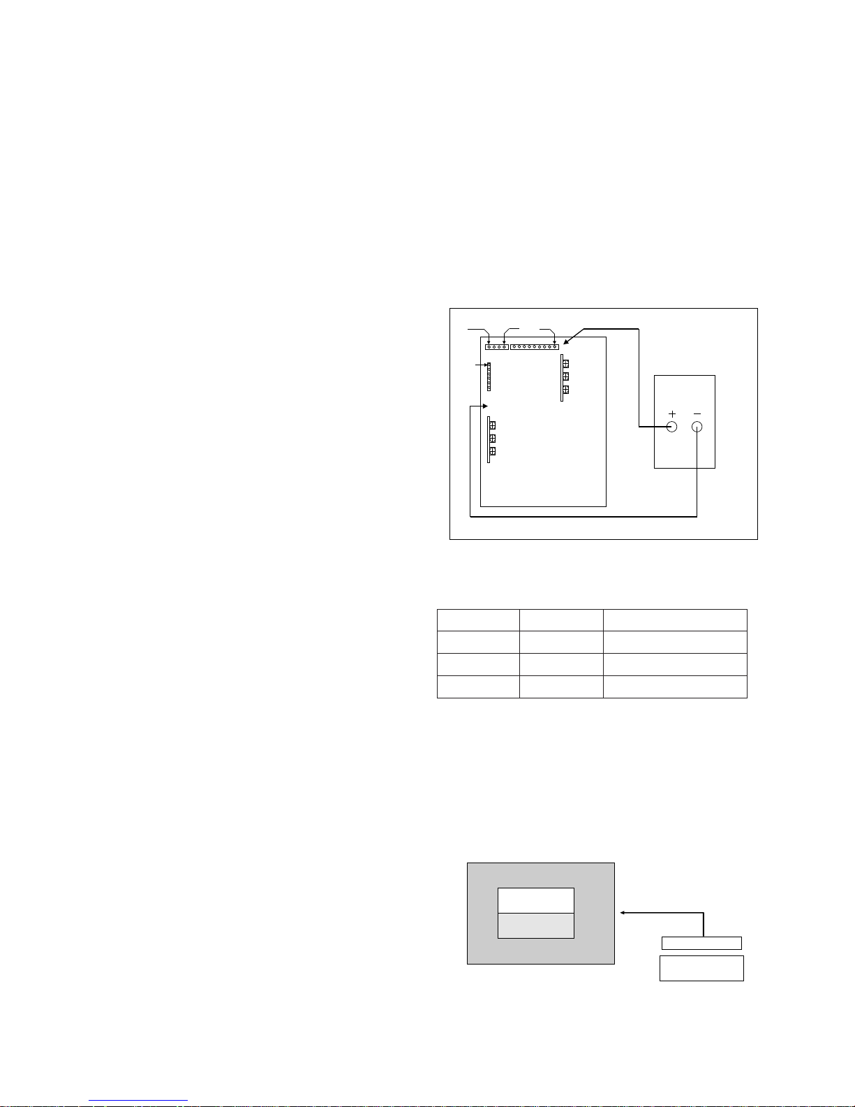
Leakage Current Cold Check(Antenna Cold Check)
With the instrument AC plug removed from AC source,
connect an electrical jumper across the two AC plug prongs.
Place the AC switch in the on positioin, connect one lead of
ohm-meter to the AC plug prongs tied together and touch other
ohm-meter lead in turn to each exposed metallic parts such as
antenna terminals, phone jacks, etc.
If the exposed metallic part has a return path to the chassis, the
measured resistance should be between 1MΩ and 5.2MΩ.
When the exposed metal has no return path to the chassis the
reading must be infinite.
An other abnormality exists that must be corrected before the
receiver is returned to the customer.
Leakage Current Hot Check (See below Figure)
Plug the AC cord directly into the AC outlet.
Do not use a line Isolation Transformer during this check.
Connect 1.5K/10watt resistor in parallel with a 0.15uF capacitor
between a known good earth ground (Water Pipe, Conduit, etc.)
and the exposed metallic parts.
Measure the AC voltage across the resistor using AC
voltmeter with 1000 ohms/volt or more sensitivity.
Reverse plug the AC cord into the AC outlet and repeat AC
voltage measurements for each esposed metallic part. Any
voltage measured must not exceed 0.75 volt RMS which is
corresponds to 0.5mA.
In case any measurement is out of the limits sepcified, there is
possibility of shock hazard and the set must be checked and
repaired before it is returned to the customer.
Leakage Current Hot Check circuit
1.5 Kohm/10W
To Instrument's
exposed
METALLIC PARTS
Good Earth Ground
such as WATER PIPE,
CONDUIT etc.
AC Volt-meter
IMPORTANT SAFETY NOTICE
0.15uF
Page 4
- 4 -
SPECIFICATIONS
Note : Specification and others are subject to change without notice for improvement.
O MONITOR
O Video receiving system:
PAL
SECAM
NTSC
VGA
SVGA
O Input Voltage : AC 110~240V, 50/60Hz
O Power consumption : Max 330W
Stand-By : 5W
O PDP Module : PDP40NVVDN4
O Speaker Impedance : 8 ohm
O Sound output : 20W max
O Feature : AV Input (Bottom)
Component Input (Bottom)
RGB Input (Bottom,D-Sub 15pin)
External SPK Out (Bottom,SPK Jack)
STB Control Input (Bottom)
STB Audio Input (D-Sub 25pin)
O Funtion : PSM
SSM
Child Lock
Auto Sleep
O External Interface
AV/COMPONENT Output
COMPONENT Mode ( Y,Cb/Pb,Cr/Pr)
OSET TOP BOX
O Video receiving system:
PAL-BG/DK/I
NTSC M
O Input Voltage : AC 110~250V, 50/60Hz
O Tuning System : FVS 100 Program
O Power consumption : Max 35W
Stand-By : 5W
O Available Channel : VHF : E2~E12(L/L’:B,C,D)
UHF : E21~E69
CATV : S1~S20(HYPER:S21~S41)
O Feature : AV In/out(RCA) : AV1(With RGB in/TV out)
AV In/out(RCA) : AV2(Monitor out)
AV In : AV3(Rear,CVBS)
S-Input : S-Input
Y,Pb,Pr Input : Component(Rear,480I,480P)
RGB Input : RGB-PC(Rear,D-Sub 15pin)
Audio-Input : Component/RGB- PC
RGB out : RGB-PC(Rear,D-Sub 15pin)
RGB out/Control :
PDP MNT connection:RGB,Control
AUDIO out :
PDP MNT connection:L,R(D-Sub 25pin)
Woofer out :
Woofer Speaker
O Funtion : PSM
SSM
Teletext
Auto Sleep
ITEM
AV Video out
AV SYNC out
AV Burst out
AV Audio Out
MIN
0.85
0.25
0.15
0.40
TYP
1.00
0.30
0.30
0.50
MAX
1.15
0.35
0.35
0.60
UNIT
Vpp
Vpp
Vpp
V
PIn Name
R
G
B
GND
H.Sync
V.Sync
STB-DET
SCL
SDA1 out
SDA1 in
SDA2 out
SDA2 in
Spec.
0.7Vpp
¡ 0.05
0.7Vpp¡ 0.05
0.7Vpp¡ 0.05
Case Common
4.0Vpp¡ 0.5
3.0Vpp¡ 0.5
High/Low
3.0~4.5Vpp
3.0~4.5Vpp
3.0~4.5Vpp
3.0~4.5Vpp
3.0~4.5Vpp
Pin
VSC-Det
GND
GND
GND
GND
GND
GND
GND
GND
GND
GND
GND
No.
13
14
15
16
17
18
19
20
21
22
23
24
REsolution
640*480
640*480
704*480
H-Freq(Khz)
15.73
15.63
31.47
V-Freq(hz)
60
50
59.94
Proposed
SDTV,DVD 480I
SDTV,DVD 480I
SDTV 480P
RGB/HV Control Signal In/Out(D-Sub 25pin Cable)
Page 5
- 5 -
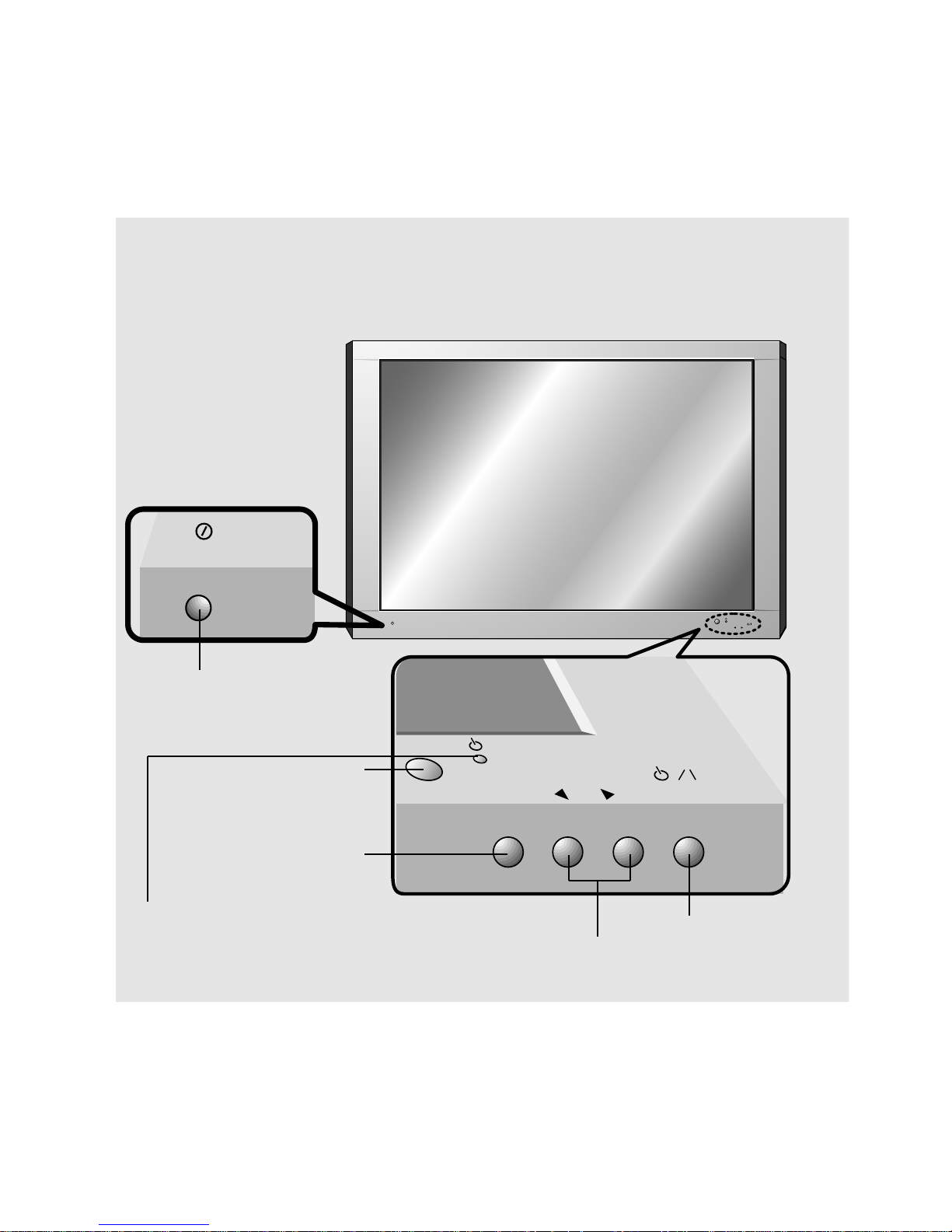
CONTROLS DESCRIPTION
ON/OFF
VOLUME
INPUT
SELECT
ON/OFF
INPUT
VOLUME
SELECT
<Front Panel>
MAIN POWER BUTTON
INPUT SELECT BUTTON
REMOTE CONTROL SENSOR
POWER/STANDBY INDICATOR
Illuminates red in standby
Illuminates green when the Monitor is switched on
POWER BUTTON
VOLUME (FF,GG) BUTTON
Page 6
- 6 -
P
B R
Y P
(+) ( ) (+)( )
AC INPUT
EXTERNAL SPEAKER (8Ω)
AV INPUT
RGB-PC INPUT(VGA/SVGA)
R RL L R
AUDIO INPUT RGB INPUT/CONTROL
L
AUDIO
(MONO)
VIDEO
COMPONENT (480i/480p)
(DVD INPUT)
PBY
R
P
(+) ( ) (+)( )
AC INPUT
EXTERNAL SPEAKER (8Ω)
AV INPUT
(DVD INPUT)
COMPONENT (480i/480p)
RRL
L
R
AUDIO INPUT RGB INPUT/CONTROL
L
AUDIO VIDEO
(MONO)
RGB-PC INPUT(VGA/SVGA)
<Back Panel>
EXTERNAL
SPEAKER (8Ω)
KNOBS
AV INPUT /
COMPONENT (480i/480p)
DVD INPUT SOCKETS
RGB-PC INPUT (VGA/SVGA) /
AUDIO INPUT /
RGB INPUT/CONTROL SOCKETS
POWER INPUT
SOCKET
This Monitor operates
on an AC mains supply,
the voltage is as indicated as inside back cover
of this manual. Never
apply DC power to the
Monitor.
Page 7
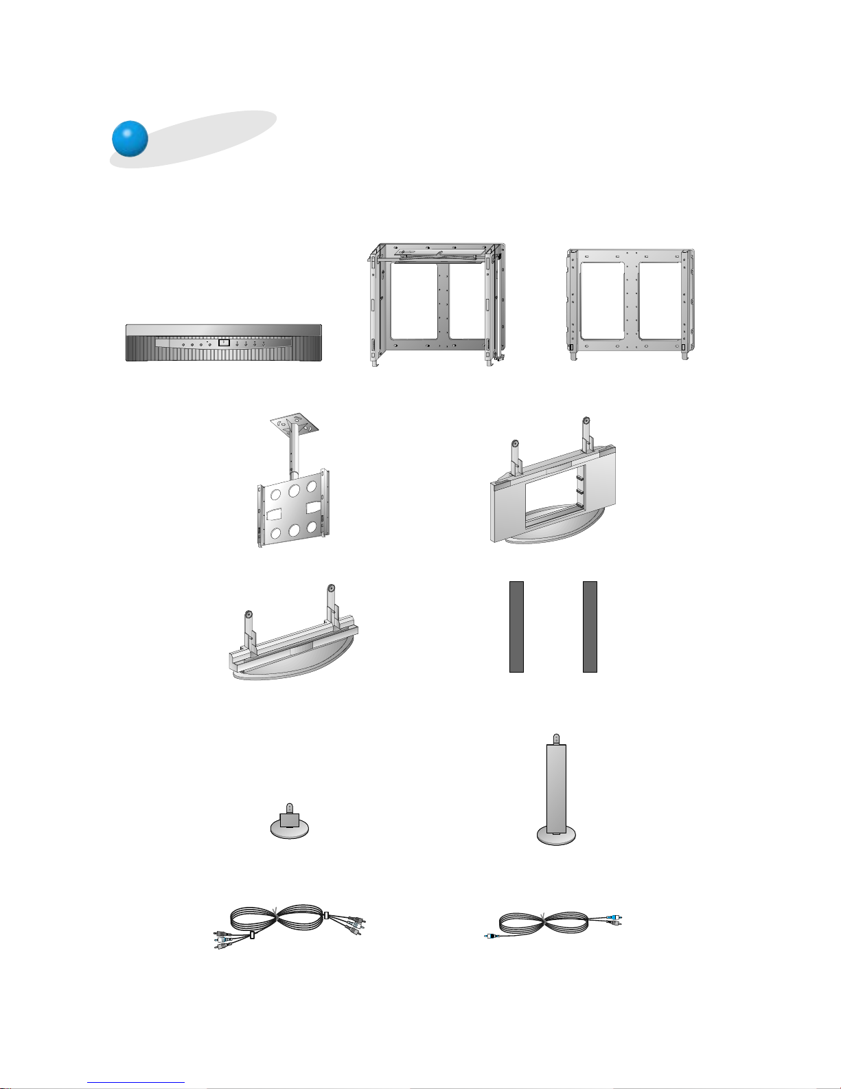
- 7 -
AP-40/42WA20M
(Tilt wall mounting bracket)
AP-40/42WA10
(Wall mounting bracket)
MULTIMEDIA
ON/OFF
TV/VIDEO MENU ENTER
VOL CH
RT/RZ-BA10 (PDP Tuner)
Optional Extras
- Optional extras can be changed or modified for quality improvement without any notification new
optional extras can be added.
- Contract your dealer for buying these items.
AP-40/42CA10 (Ceiling mounting bracket)
AP-40/42FA10 (Floor type stand)
AP-40/42DA10 (Desktop stand)
AP-40/42SA10 (Speakers)
AP-40/42SA10D
(Speaker stand)
AP-40/42SA10F
(Floor type speaker stand)
Video cables
Audio cables
Page 8
- 8 -
1. Application Object
These instructions are applied to all of the PDP monitor, MP00MB.
2. Notes
(1) Because this is not a hot chassis, it is not necessary to use
an isolation transformer. However, the use of isolation
transformer will help protect test instrument.
(2) Adjustment must be done in the correct order.
(3) The adjustment must be performed in the circumstance of
25±5°C of temperature and 65±10% of relative humidity if
there is no specific designation.
(4) The input voltage of the receiver must keep 220/230V,
50/60Hz in adjusting.
(5) The receiver must be operated for about 15 minutes prior
to the adjustment.
¤ After receiving 100% white pattern, the receiver must be
operate prior to adjustment.(Or white condition in HEATRUN mode)
¤ŁEnter into HEAT-RUN mode
- Select the HEAT-RUN OFF by pressing ADJ button on
Remote Control for adjustment.
- Press the VOL + button in HEAT-RUN OFF.
(OSD display HEAT-RUN WHITE and screen display
100% full WHITE PATTERN)
¤ØSet is activated HEAT-RUN without SET TOP BOX or
signal generator in this mode.
[ Single color pattern of HEAT-RUN mode uses to check
PANEL.(RED/BLUE/GREEN)
[Caution] If you turn on a still screen more than 20 minutes, a
afterinage may be occur in the black level part of the
screen.
3. POWER PCB Assy Voltage Adjustment
[ Replace PDP Module or Power Board, adjust certainly Power
PCB Assy Voltage.
3-1. Test Equipment
D.M.M 1EA
3-2. Connection Diagram for Measuring
Refer to Fig 1.
3-3. Adjustment Method
(1) Va Adjusment(Address Voltage Adjusment)
¤ Connect pin 1 of P806 or P811 to (+) jack of D.M.M.
¤ŁAfter turning the VR803(Va Adj), voltage of D.M.M
adjustment as same as Va voltage which on label of
panel right/bottom.(Deviation : ±0.5V)
(2) Vs Adjustment
¤ Connect pin 9 of P803 to (+) jack of D.M.M.
¤ŁAfter turning the VR804(Vs Adj), voltage of D.M.M
adjust as same as Vs voltage which indicated on label
of panel right/bottom.(Deviation : ±0.5V)
(3) VSC Adjustment
¤ Connect pin 4 of P802 to (+) jack of D.M.M.
¤ŁAfter turning the VR806(VSC Adj), voltage of D.M.M
adjust as same as Vs voltage which indicated on label
of panel right/bottom.(Deviation : ±0.5V)
(4) VSETUP Adjustment
¤ Connect pin 1 of P802 to (+) jack of D.M.M.
¤ŁAfter turning the VR805(VSETUP Adj),voltage of D.M.M
adjust as same as Vs voltage which indicated on label
of panel right/bottom.(Deviation : ±0.5V)
4. Adjustment of RGB Cut-off and
White Balance
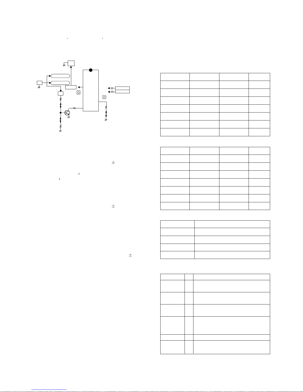
4-1. Required Equipment
Color analyzer(CA-100 or same production)
4-2. Connection Diagram of Equipment for
Measuring
ADJUSTMENT INSTRUCTIONS
VSETUP
VR806
VR805
VR804
DMM
VSC
VA
VSC CTL
V
A CTL
P814
VR803
GND
V
SETUP CTL
V
S CTL
V
S
<Fig 1> Connection Diagram of Power Adjustment for Measuring
Refer to Typical Voltage
Va
Vs
Vsc
Vsetup
70V
182V
75V
225V
Address Voltage
Sustain Voltage
Scan Voltage
Setuo Voltage
COLOR
ANALYZER
TYPE; CA-100
Window Pattern
CVBS Signal Input
High Light
120±5cd/m2
Low Light
6±1cd/m2
PDP MONITOR
MSPG-2100 or
MSTG-5200
<Fig 2> Connection Diagram of Automatic Adjustment
Page 9

- 9 -
4-3. Adjustment of RGB CUT OFF
(1) Select A/C SRT (cut-off automatic adjustment ) by
pressing SVC button on Remote Control for adjustment.
(2) Press the VOL + or VOL - button.
(3) It displayed all of the black on the screen and then
adjustment is started.
(4) If adjustment is finished, exit from adjustment mode by
pressing A/V button.
4-4. Adjustment of White Balance
• White Balance should be done after RGB cut-off become
adjustment.
• Operate the Zero-calibration of the CA—100, then stick
sensor to PDP module surface when you adjust.
(1) Select WHITE PATTERN of HEAT RUN mode by pressing
SVC button on Remote Control for adjustment then
operate HEAT RUN more than 15 minute.
(2) Supply window Signal in pattern generater.
[ When adjustment is operated manually, perate process (3)
to (6) regular sequence, when adjustment is operated
automatically perate process (1)~(2).
(3) To adjust Low Light, stick sensor to pattern(Dark), select
the R cut/B cuby pressing SVC button on Remote Control
for adjustment and adjust it until color coordination
becomes X=0.280±0.003, Y=0.310±0.003 and color
temperature becomes 8.800
cK ± 500cK by pressing VOL+,
- button. (G-cut fixation)
(4) To adjust High Light, stick sensor to pattern(White).
Select the R Gain/G Gain(adjustment 6) by pressing SVC
button on Remote Control for adjustment and adjust R
Gain/G Gain until color coordination becomes
X=0.280±0.003, Y=0.310±0.003 and color temperature
becomes 8.800cK ± 500cK.(B-Gain fixation)
(5) Confirm the result of the High Light adjustment.
If the deviation of High Light occur, operate the adjustment
of Low Light and High Light again.
(6) Exit adjustment mode using AV button.
5. Color Temperature of STB
White Balance Adjustment
5-1. Required Equipment
Color Analyzer(CA-110, CA-100 or same production)
5-2. Connection diagram of equipment for
measuring
(1) To adjust the deviation of the STB signal output.
(2) Use regular PDP Monitor(JIG).
5-3. Adjustment Method
• Connect the STB to regular PDP Monitor.
• Operate the zero-calibration of the CA-100, then stick
sensor to surface of PDP module when you adjust.
(1) Select ITE PATTERN of HEAT RUN mode by pressing
SVC button on Remote Control for adjustment, then
operate HEAT RUN more than 15 minute.
(Operate the HEAT RUN to adjust the STB at first, then if
OFF hour don’t keep more than 3 minutes, operate next
adjustment of the STB without HEAT RUN.)
(2) Supply window Signal to TD-710 in pattern generator.
[ When adjustment is operated manually, perate process (3)
to (7) regular sequence, when adjustment is operated
automatically perate process (1) to (2).
(3) Select STB CXA2101 by pressing SVC,ADJUST button on
Remote Control for adjustment.
(4) To adjust Low Light, stick sensor to 9th pattern(Dark).
Select the B Cut/R Cut, then adjust the B Cut/R Cut until
color coordination becomes X=0.280±0.003,
Y=0.310±0.003 and color temperature becomes 8.800cK ±
500cK by pressing VOL+, - button. (Adjust in B Cut 10±1,
R Cut 6±1)
(5) To adjust High Light, stick sensor to 2th pattern(White).
Select the R Gain/G Gain, then adjust the R Gain/G Gain
until color coordination becomes X=0.280±0.003,
Y=0.310±0.003 and color temperature becomes 8.800cK
±500cK. (B-Gain fixation)
(6) Confirm the result of the High Light adjustment.
If the deviation of High Light occur, operate the adjustment
of Low Light and High Light again.
(Expectation average adjustment data : B-Cut & RCut=6±2, R-Gain/G-Gain=25±3)
(7) Exit adjustment mode using A/V button.
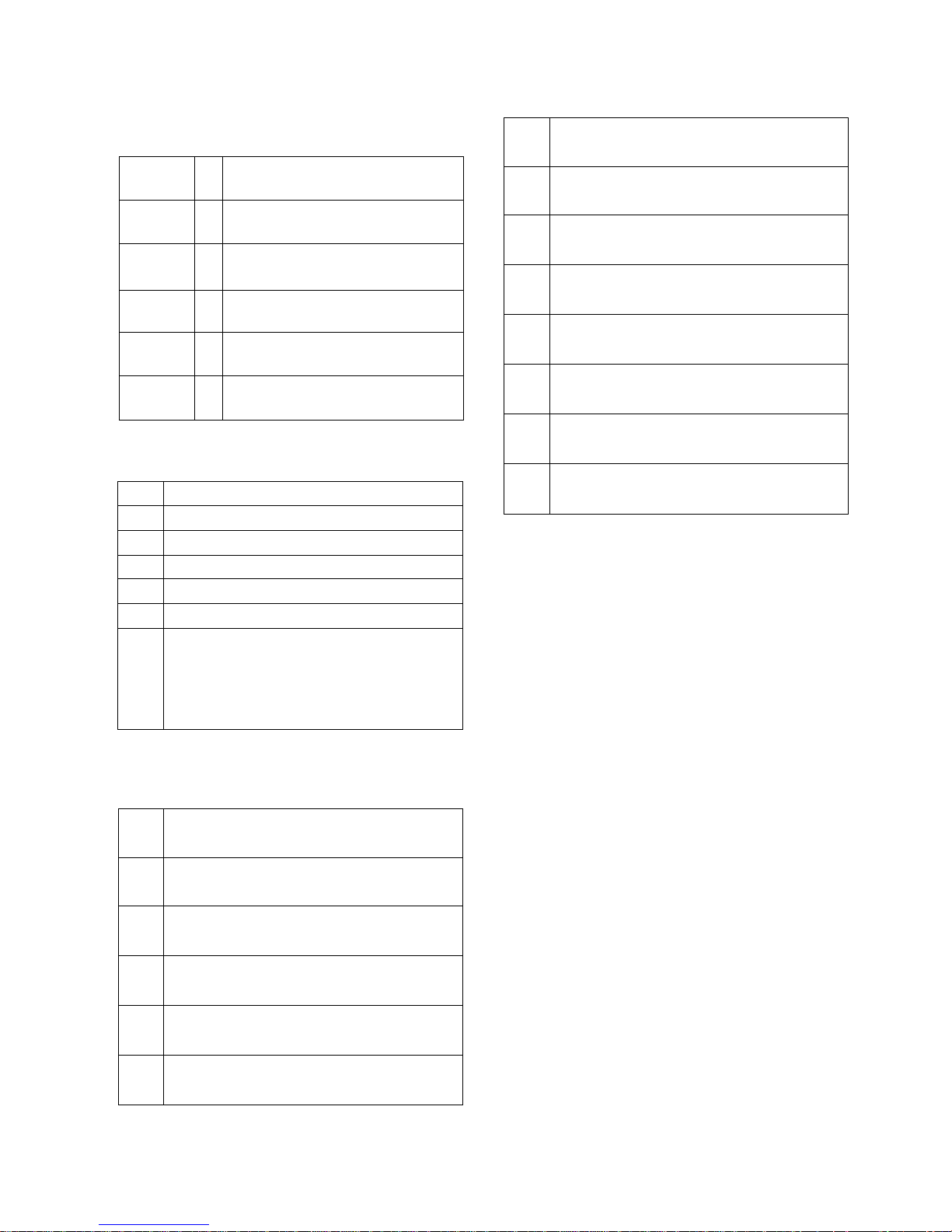
6. Adjustment of VIF-VCO COIL
6-1. Preparation for Adjustment
(1) Connect the equipment for measuring as below.
(2) Setting equipment for measuring.
RF Signal generator
COLOR
ANALYZER
TYPE; CA-100
CVBS Signal Input
PDP MONITOR
RT-BA10(STB)
Window Pattern
MSPG-2100 or MSTG-5200
High Light
120±5cd/m2
Low Light
6±1cd/m2
<Fig 3> Connection Diagram of STB Automatic Adjustment
ADJ.Point
X106
VR101
System
B/G,D/K/I,SECAM-L
SECAM-L’
Frequency
38.9
34.25
Modulation
OFF
OFF
Level
80dBuV
80dBuV
Page 10
* If any model don t have SECAM-L/L System, you should not
operate adjustment of VR101.
* Output of Power Supply = DC 5V
* Oscilloscope range = set 0.5V/div., 5msec/Div.(using scope)
6-2. Adjustment 38.9MHz IF(B/G, D/K, I, L, M)
(1) Input the signal of the signal generater(38.9MHz) to
TP105(IC102 pin 7) through 0.01uF(103) capacitor.
(2) S1 : OFF, S2 : IN, S3 : OFF
(3) Adjust voltage of the TP103 to 2.5
0.1V by adjusting
X106.
6-3 Adjustment L VCO(Adjustment
SECAM-L ) --> Only SECAM L model
(1) After changing the signal of the signal generater to
34.25MHz, input the signal to TP102(IC102 pin 11) through
0.01uF(103) capacitor.
(2) S1 : on, S2 : off, S3 : ON
(3) Adjust voltage of the TP103 to 2.5
0.1V by adjusting
VR101.
7. Adjustment AGC
7-1 Preparation for Adjustment
(1) Connect the signal of PAL-B/G 05ch. to Antenna jack.
(2) Connect Multi meter to point(J150) of AGC adjustment.
7-2 Adjustment
Adjustment the voltage of Multi meter to 2.3 0.1V by
changing VR102.
8. OPTION TABLE
8-1 Funtion of Line Service
(1) • Enter to SVC mode by using SVC button on the remote
control.
•To enter to the SVC mode,press the “OK” button on RTBA10 local key ond “OK” button on the remote control
simultaneously.
• In MT-BA10 only,press the “INPUT” button and “OK” button
on remote control to enter to SVC mode.
(2) Select the item by using the Quick View(Yellow) button.
(3) After adjusting,restore adjusted item in EEPROM by using
“OK” button and use the CYAN button to cancel the
adjusted condition.
(4) Select the program directly and input the data of option by
using the number button.
(5) Line SVC-0(Hitrun&W/B Adj.mode)=> VSC EEPROM
• H/T RUN:OFF,WHITE,RED,GREEN,BLUE,OFF
• A/C SRT:Auto Cutoff
• R/G/B Fine 16,R/G/B Gain 3,R/G/B Cutoff 100
(6) Line SVC-1(Phase&Position Adj.mode)=> VSC EEPROM
• Phase 15,H-Pos 32,V-Pos 32,Auto Position
(7) VSC CXA2101 Adj.mode)=> VSC EEPROM
(8) STB CXA2101 Adj.mode)=> STB EEPROM
(9) SOUND Adj.mode => VSC EEPROM
(10) Option 1 Adj.mode => VSC EEPROM
• Select it directly by using Teletext Size button.
- 10 -
IC102
TDA4474
TP103
ST-BY 5V:P001
24
7
13
15
1
0.01uF
TP105
X106
(VCO)
5V
PowerSupply
V Multimeter or Oscilloscope
TP110
38.9MHz
34.25MHz
(B/G,D/K,I,L)
(SECAM-L')
100 ohm
S1
5V
4.7 Kohm
S3
Q122
VR122
R144
16
TP112(IF VCC)
S2
TP111
100 ohm
11 TP102
VR102(AGC)
(STB MAIN)
BC 7
RC 7
RG 10
GG 10
BG 10
SUB-CON 3
SUB-BRI 54
SUB-COL 0
SUB-HUE 14
SUB-SHP 3
CTI 0
RYR 6
GYR 10
RYB 9
GYB 5
GMM 5
BLK 15
PRE 1
DCT 1
DPI 2
VTC 3
HWI 1
DCO 1
HDT 0
SFO 1
BC 7
RC 7
RG 31
GG 31
BG 31
SUB-CON 3
SUB-BRI 54
SUB-COL 0
SUB-HUE 7
SUB-SHP 0
CTI 0
RYR 6
GYR 10
RYB 9
GYB 5
GMM 0
BLK 15
PRE 1
DCT 0
DPI 0
VTC 3
HWI 1
DCO 0
HDT 0
SFO 1
CON 25
BRI 31
COL 31
HUE 31
SHP 31
FP
NP
SP
SC VOL
STB VOL
14
80
25
83
118
System
Aus/China
ACMS
TOP
A2MONO
TXT LAN
Language
2
0
1
0
0
6
6
0:BG/I/DK 1:BG/I/DK/L 2:BG/I/DK/M
0:CCIR BG/OIRT DK
1:Australia BB/China DK
0:
1:Channel Name Labeling
0:TOP=>SIMPLE
1:TOP
0:Sound treatment normally
1:Don’t recognize the Stereo(NICAM
treatment normally) => A part of AFRICA
0:E only,1:EU5,2:NON,3:China,4:Arabic
5:Parsi,6:All
Page 11
(10) Option 2 Adj.mode
• Select it directly by using Teletext Hold button.
8-2 OSD LANGUAGE
( Select a one among Option in SVC Mode-Language item.)
8-3 TXT LANGUAGE
( Select a one among Option in SVC Mode-TXT LAN item.)
- 11 -
Turbo
I/II save
Woofer
TEXT
Vol Curve
PIP
0
1
0
0
1
0
0:NORMAL Search
1:Turbo Search not use
0:EU
1:NON EU
0:Without Woofer
1:With Woofer
0:Without TEXT
1:With TEXT
0:EU Curve
1:Non EU Curve
0:Without PIP
1:With PIP
0
1
2
3
4
5
6
E Only(English)
EU5(Enlish,German,French,Italian,Spanish)
NON 12
CHINA(English,Chinese)
ARAB(English,French,Arabic,Urdu)
PARSI(English,Parsi)
ALL(Enlish,Norwegian,Czech,German,Danish,Ru
ssian,French,Finish,Chinese,Italian,Portuguess,
Arabic,Spanish,Rumanian,Urdu,Dutch,Polish,
Persian,Swedish,Hungarian)
6
38
40
55
70
128
English,French,SWedish,Czech,German,
Spanish,Italian
Polish,French,SWedish,Czech,German,Spanish,
Italian,English
English(US),French,SWedish,Czech,German,
Spanish,Italian,English(TPU3050 US)
English,French,SWedish,Turkish,German,
Spanish,Italian,English(TPU3050 Turkish)
English(US),Slovakian,Hungarian,Serbian,
Albanian,Polish,Turkish,Rumanian
Polish,Cylrillic,Estonia,Estonia,Estonia,Estonia,
Estonia,Estonia(TPU3051)
128
129
129
130
130
131
131
132
English,French,French,French,French,French,
French,Arabic(TPU3052)
Polish,Cylrillic,SWedish,Czech,Estonia,Estonia,
Estonia,Estonia(TPU3051)
Hebrew,Hebrew,Hebrew,Hebrew,Hebrew,
Hebrew,Hebrew,Arabic(TPU3052)
English,French,SWedish,Turkish,German,
Spanish,Italian,Greek(TPU3051)
English,French,French,Turkish,French,French,
French,Italian(TPU3052)
English,Turkish,Turkish,Turkish,German,Turkish,
Turkish,Greek(TPU3051)
French,French,French,Turkish,French,French,
French,Italian(TPU3052)
English,French,French,French,French,French,
Arabic(TPU3052)
Page 12

- 12 -
BLOCK DIAGRAM
1. VSC Board
Chip for flat panel display application
VGA XGA scale up/down
Triple 8Bit, 80MSPS, 3.3V Video&Graphic Digitizer
with Digital PLL
Analog R/G/B Input to 3X8 Digital R/G/B Output
Display Processor & Scan Rate Converter
(Format Converter)
Interlace to Progressive
15KHz 31KHz(2H X 1V)
Comb Filter Video Process
CVBS(Composite Video Baseband
Signal) Input to Y/C(Y,U,V) Output
P101
V/R/L
P102
DVD
DS102
DS101
IC203
VPC3230
Decoder
80Pin
3
Y,Cb,Cr
CVBS
(A)
1
IC204
SDA9410
Deinterlace &
D/A
100Pin
&
8 LU0-7
8
CHR0-7
IC303
Video&Chroma
CXA2101AQ
80Pin
STB-R/G/B/HS/VS(A)
5
PC-R/G/B/HS/VS (A)
5
DTV-Y/Pb/Pr (A)
3
TV-Y/U/ V/HS/VS
(A)
5
THS8083
100Pin
IC304
3 CXA-R/G/B(A )
MX88L284
3X2M
Scan converter
208Pin
IC401
IC001
M37270
Micro-Com
IC403
2M
SDRAM
IC402
2M SDRAM
(R/G/B)(D)
CAX-HS/VS
2
16
D0-16
A0-10
D16-31
11
16
OSD_R/G/B/YS
4
IC501
74F541
IC502
74F541
IC503
74F541
Buffer
IC504
74F541
OSD_HS/VS
2
HS/VS/Black/Clk
4
8
DOR0-7
8
DOG0-7
8
DOB0-7
STB-POWER
VSC DET/POWER
HDSTB_DET
STB_SCL/SDA
ANA_STB_DET
7
PVS/PHS
Black/Clk
4
PAR0-7
8
PAG0-7
8
PAB0-7
8
PD501
(41Pin)
PDP Module
(D)
3X8
Multi-Component Processor
(Baseband Video Signal Processor)
STB, PC, DTV, TV signals Input to Analog R/G/B Output
D-sub
25
D-sub
15
IC604
LA7222
(Audio S/W)
(A)
P601
L/R
RGB-PC
AV/DVD/COMPONENT
IC602
CXA2022S
(Tone Control)
IC603
LA4282
Audio Amp.
(12Wx2)
L/R
P007A
(Spk. Jack)
I C
IC203,204,303,304,407
IC002
24C16
IC407
SC786102DW
OSD IC
2 22
L/R
L/R
HS/VS
SDA2
SCL2
LLC1/2
2
VS
PLL HS/
CLK
2
Page 13

- 13 -
2. STB Main
TUNER
CXA2069Q
A/V SW
DC 12V
V, L/R
CVBS
(RCA JACK)
V, L/R
* SCART2 : HALF
* RCA Jack
Common Use
*PCB LayOut)
V, L/R
TV, L/R
(SCART1: FULL)
Y / C
AUDIO
COMMON USE
MSP3411G
Sound
Processor
DC 8V
2 nd
SIF
L/R(TV)
L/R
(RCA JACK)
L/R
CVBS1/Y
TPU3052S
TELETEXT
DC5V
VPC3230D
MAIN
[ADDR: 47]
Video
Processor
DC 6V
C
DVD Y/Cr/Cb
(A)
VPC3230D
SUB
Processor
DC6V
[ADDR: 44]
Video
SDA9410
1H/1V=> 2H/ 1V
DW / PIP / MPIP
DC 3.3V
L / R OUT
CXA2101AQ
RGB
Processor
DC9V
DTV Y, Pb, Pr (A)
H V
R/G/B/HS/VS(A)
CVBS2/Y
R/G/B
HS/VS(A)
R/G/B
HS/VS(A)
IF IC
TDA4474
DC5V
FB
CVBS.3
RGB
C
EXT_RGB
BA7657F
RGB
S/W
DC 5V
R/G/B
HS/VS(A)
81
FIFO
Memory
V04160
RE
WE
RF
SVHS
AV3
AV2
MNT
OUT
DVD/DTV
TV
OUT
AV1
P801
7PIN
Y/ C/HS/VS (D)
M37272
u-COM
IC 001
KEY-1
K
IN
K
OUT
I
2
C
SCL-A
SDA-A
I
2
C
SCL-A
SDA-A
I
2
C
SCL-A
SDA-A
I
2
C
SCL-A
SDA-A
I
2
C
SCL-D
SDA-D
I
2
C
SCL-D
SDA-D
DS 701
(25Pin
Cable)
SCL-A/D
SDA-A/D
9
10
PC- IN
PC- OUT
PC Audio(Stereo)
Page 14

- 14 -
WIRING DIAGRAM
P15
P004B
P004A
P14
PD501
P100
P802
P803
P802
P801
P006A
P810
P811
P806
P801
P809
P815
P005A
P003A
P304
P007B
P007A
P302
P301
P303
P807
P805
P804
P102
Page 15

MEMO
- 15 -
Page 16

- 16 -
EXPLODED VIEW (MONITOR)
300
301
303
305
302
200
201
202
203
204
205
206
210
207
209
208
400
401
550
551
530
570
540
520
560
211
212
Page 17

- 17 -
EXPLODED VIEW PARTS LIST
200 6348Q-A002A PDP,40” 4:3 640*480 DOUBLE SCAN
201 6871VSN168A X RIGHT TOP B/D ASSY
202 6871VSN168B X LEFT TOP B/D ASSY
203 6871VSN168C ZCNT TOP B/D ASSY
204 6871VSN168D ZSUS B/D ASSY
205 6871VSN168E ZCNT BOTTOM B/D ASSY
206 6871VSN168F X LEFT BOTTOM B/D ASSY
207 6871VSN168G X RIGHT BOTTOM B/D ASSY
208 6871VSN168H YDRU B/D ASSY
209 6871VSN168J YSUS B/D ASSY
210 6871VSN168K CTRL B/D ASSY
211 4980V00164B SUPPORTER,VERTICAL
212 4980V00164B SUPPORTER,VERTICAL
300 3091V00288C CABINET ASSY LG
3091V00288H CABINET ASSY (SILVER, GREAT WALL)
3091V00288F CABINET ASSY (GOLD)
3091V00A26A CABINET ASSY (40PA20S,LG)
3091V00A26H CABINET ASSY (40PA20S,NO BRAND)
301 4980V00183B SUPPORTER,FILTER(TOP)
302 4980V00180B SUPPORTER,FILTER(BOTTOM )
303 4980V00181B SUPPORTER,FILTER(SIDE)
305 3790V00287A WINDOW FILTER
400 3809V00212C BACK COVER ASSY
3809V00212H BACK COVER ASSY (SILVER, GREAT WALL)
3809V00212F BACK COVER ASSY (GOLD)
401 3301V00005A PLATE ASSY,REAR A/V
3301V00005E PLATE ASSY,REAR A/V (SILVER)
3301V00005D PLATE ASSY,REAR A/V (GOLD)
520 6871VMM704A PWB ASSY,MAIN VSC
530 3501V00028A BOARD ASSY,PDP POWER LINE FILTER
540 6871VSM689A PWB ASSY,CONT
550 6871VSM690A PWB ASSY,PSW
551 5020V00445A BUTTON,POWER
560 6871VSM692A PWB ASSY,AUDIO
570 3501V00027E BOARD ASSY,PDP POWER
No.
Part No.
Description
Page 18

- 18 -
EXPLODED VIEW (SET TOP BOX)
400
174
410
530
300
550
315
320
330
316
311
310
520
540
Page 19

- 19 -
EXPLODED VIEW PARTS LIST
174 174-322G POWER CORD VDE 2400MM HOUSING BLAC
300 3110V00101B CASE ASSY,BOTTOM
310 5020V00443A BUTTON,CONTROL 4KEY
311 5020V00448A BUTTON,CONTROL 4KEY
315 3720V00079A PANEL,FRONT
316 3720V00080B PANEL,CONTROL
320 320-062H SPRING,COIL
330 5020V00444B BUTTON,POWER
400 3110V00102A CASE ASSY,TOP
410 3110V00111C CASE ASSY,REAR
520 6871VMM677A PWB ASSY,MAIN RT-BA10(TPU3052)(PH+PH)
6871VMM677B PWB ASSY,MAIN RT-BA10(TPU3050)(PH+PH)
6871VMM677C PWB ASSY,MAIN RT-BA10(TPU3051)(PH+PH)
530 6871VPM062A PWB ASSY,SMPS MP-00MB STB(TD-711)
540 6871VSM658A PWB ASSY,A/V
550 6871VSM718A PWB ASSY,CTL
No.
Part No.
Description
Page 20

- 20 -
REPLACEMENT PARTS LIST(MONITOR)
LOCA. NO PART NO DESCRIPTION
D401
D402
D601
D602
D603
D604
D605
D606
LD001
LED002
LED003
IC006
IC007
Q001
Q001
Q002
Q002
Q020
Q021
Q102
Q103
Q104
Q105
Q106
Q107
Q108
Q109
Q110
Q111
Q201
Q202
Q301
Q302
Q303
Q601
Q603
C001
C002
C003
C008
C011
C016
C022
C026
C038
C045
C105
C107
C109
0DD226239AA
0DD226239AA
0DD226239AA
0DD184009AA
0DD184009AA
0DD184009AA
0DD184009AA
0DD184009AA
0DL200000CA
0DL112100AA
0DL112100AA
0TR830009BA
0TR830009BA
0TR319809AA
0TR387500AA
0TR319809AA
0TR387500AA
0TR387500AA
0TR387500AA
0TR387500AA
0TR387500AA
0TR387500AA
0TR387500AA
0TR387500AA
0TR387500AA
0TR387500AA
0TR387500AA
0TR387500AA
0TR387500AA
0TR150400BA
0TR150400BA
0TR150400BA
0TR150400BA
0TR150400BA
0TR150400BA
0TR150400BA
0CN1040K949
0CE476DD618
0CE108BF618
0CE108BF618
0CE108BF618
0CE108BF618
0CE107DF618
0CE107DF618
0CE107DF618
0CE107DF618
0CE107DF618
0CE107DF618
0CE476DF618
DIODE,SWITCHING CHIP KDS226 SOT-23
DIODE,SWITCHING CHIP KDS226 SOT-23
DIODE,SWITCHING CHIP KDS226 SOT-23
DIODE,SWITCHING KDS184S CHIP 85V 300MA KEC TP
DIODE,SWITCHING KDS184S CHIP 85V 300MA
KEC TP
DIODE,SWITCHING KDS184S CHIP 85V 300MA KEC TP
DIODE,SWITCHING KDS184S CHIP 85V 300MA KEC TP
DIODE,SWITCHING KDS184S CHIP 85V 300MA KEC TP
LED,SAM5670(DL-2LRG) BK Y-GREEN -
LED,SR3411(DL-11S2RN1) BK RED -
LED,SR3411(DL-11S2RN1) BK RED -
TR,BSS83 TP PHILIPS NON N-CHANNEL
TR,BSS83 TP PHILIPS NON N-CHANNEL
TR,KTC3198-TP-Y (KTC1815)KEC
TR,CHIP 2SC3875S(ALY) KEC
TR,KTC3198-TP-Y (KTC1815)KEC
TR,CHIP 2SC3875S(ALY) KEC
TR,CHIP 2SC3875S(ALY) KEC
TR,CHIP 2SC3875S(ALY) KEC
TR,CHIP 2SC3875S(ALY) KEC
TR,CHIP 2SC3875S(ALY) KEC
TR,CHIP 2SC3875S(ALY) KEC
TR,CHIP 2SC3875S(ALY) KEC
TR,CHIP 2SC3875S(ALY) KEC
TR,CHIP 2SC3875S(ALY) KEC
TR,CHIP 2SC3875S(ALY) KEC
TR,CHIP 2SC3875S(ALY) KEC
TR,CHIP 2SC3875S(ALY) KEC
TR,CHIP 2SC3875S(ALY) KEC
TR,CHIP 2SA1504S(ASY) KEC
TR,CHIP 2SA1504S(ASY) KEC
TR,CHIP 2SA1504S(ASY) KEC
TR,CHIP 2SA1504S(ASY) KEC
TR,CHIP 2SA1504S(ASY) KEC
TR,CHIP 2SA1504S(ASY) KEC
TR,CHIP 2SA1504S(ASY) KEC
0.1M 50V Z F TA52
47UF STD 10V 20% FL TP 5
1000UF KME 16V M FL TP5
1000UF KME 16V M FL TP5
1000UF KME 16V M FL TP5
1000UF KME 16V M FL TP5
100UF STD 16V M FL TP5
100UF STD 16V M FL TP5
100UF STD 16V M FL TP5
100UF STD 16V M FL TP5
100UF STD 16V M FL TP5
100UF STD 16V M FL TP5
47UF STD 16V M FL TP5
LOCA. NO PART NO DESCRIPTION
IC001
IC002
IC003
IC004
IC005
IC101
IC102
IC201
IC202
IC203
IC204
IC301
IC302
IC303
IC304
IC401
IC402
IC403
IC404
IC406
IC407
IC501
IC502
IC503
IC504
IC601
IC602
IC604
D002
D003
D004
D005
D006
D009
D010
D011
D012
D013
D101
D102
D103
D104
D105
D106
D107
D201
D202
D301
D302
0IZZVA0025A
0IAL241600B
0IFA753307A
0IFA754207A
0IFA754207A
0IPH827150A
0IKE780500D
0ISH323422A
0ISH323422A
0IIT323000D
0ISM941000A
0ISH092100B
0ISH323422A
0ISO210100B
0ITI808300B
0IMR882840B
0IEB121616A
0IEB121616A
0ISH323422A
0ISH323422A
0ICTMMO003A
0IPH745410A
0IPH745410A
0IPH745410A
0IPH745410A
0ISH092100B
0ISO202200A
0ISA722200A
0DD226239AA
0DD226239AA
0DD226239AA
0DD226239AA
0DD226239AA
0DD226239AA
0DD226239AA
0DD226239AA
0DD226239AA
0DD226239AA
0DD226239AA
0DD226239AA
0DD226239AA
0DD226239AA
0DD226239AA
0DD226239AA
0DD226239AA
0DD226239AA
0DD226239AA
0DD226239AA
0DD226239AA
IC,CXP750010 64 BK MT-40PA10 VSC
IC,AT24C16-10PC 8D EEPROM 16K
IC,KA75330ZTA(KA7533ZTA) 3P,TO-92
IC,KA75420ZTA(KA7542ZTA) 3P,TO-92
IC,KA75420ZTA(KA7542ZTA) 3P,TO-92
IC,P82B715T 8SOP R/TP IIC EXTENDE
IC,KIA7805P(KIA78005AP),KEC
IC,PQ3RF23 4P(TO-220) 3.3V REGUL
IC,PQ3RF23 4P(TO-220) 3.3V REGUL
IC,VPC3230D QA B4 80P QFP TRAY SO
IC,SDA9410 100QFP BK SCAN CONVERT
IC,PQ09RD21 4SIP
IC,PQ3RF23 4P(TO-220) 3.3V REGUL
IC,CXA2101AQ 80P,QFP BK VIDEO SIG
IC,THS8083 100QFP BK ADC IC PD-40
IC,MX88L284-V 208QFP BK SCALE MF0
IC,M12L16161A-7T 50P TSOP ST 16M(
IC,M12L16161A-7T 50P TSOP ST 16M(
IC,PQ3RF23 4P(TO-220) 3.3V REGUL
IC,PQ3RF23 4P(TO-220) 3.3V REGUL
IC,SC786107DWR2 MOTOROLA
IC,74F541 20P SOT BK BUFFER MXIC
IC,74F541 20P SOT BK BUFFER MXIC
IC,74F541 20P SOT BK BUFFER MXIC
IC,74F541 20P SOT BK BUFFER MXIC
IC,PQ09RD21 4SIP
IC,CXA2022S 30P SDIP ST TONE CONT
IC,LA7222 (1280 AUDIO)
DIODE,SWITCHING CHIP KDS226 SOT-23
DIODE,SWITCHING CHIP KDS226 SOT-23
DIODE,SWITCHING CHIP KDS226 SOT-23
DIODE,SWITCHING CHIP KDS226 SOT-23
DIODE,SWITCHING CHIP KDS226 SOT-23
DIODE,SWITCHING CHIP KDS226 SOT-23
DIODE,SWITCHING CHIP KDS226 SOT-23
DIODE,SWITCHING CHIP KDS226 SOT-23
DIODE,SWITCHING CHIP KDS226 SOT-23
DIODE,SWITCHING CHIP KDS226 SOT-23
DIODE,SWITCHING CHIP KDS226 SOT-23
DIODE,SWITCHING CHIP KDS226 SOT-23
DIODE,SWITCHING CHIP KDS226 SOT-23
DIODE,SWITCHING CHIP KDS226 SOT-23
DIODE,SWITCHING CHIP KDS226 SOT-23
DIODE,SWITCHING CHIP KDS226 SOT-23
DIODE,SWITCHING CHIP KDS226 SOT-23
DIODE,SWITCHING CHIP KDS226 SOT-23
DIODE,SWITCHING CHIP KDS226 SOT-23
DIODE,SWITCHING CHIP KDS226 SOT-23
DIODE,SWITCHING CHIP KDS226 SOT-23
IC
TRANSISTOR
DIODE
CAPACITOR
Page 21

- 21 -
LOCA. NO PART NO DESCRIPTION
C111
C112
C115
C118
C124
C201
C203
C206
C207
C212
C225
C229
C231
C233
C235
C238
C240
C241
C242
C243
C244
C245
C279
C306
C318
C325
C326
C330
C338
C340
C343
C347
C349
C351
C353
C355
C357
C360
C401
C412
C414
C415
C418
C420
C424
C433
C445
C453
C457
C470
C502
C601
0CE476DF618
0CE476DF618
0CE476DF618
0CE476DF618
0CQ3331N509
0CE107DF618
0CE107DF618
0CE107DF618
0CE107DF618
0CK224DF56A
0CE107DF618
0CE476DF618
0CE107DF618
0CE107DF618
0CE476DF618
0CE107DF618
0CE107DF618
0CE107DF618
0CE107DF618
0CE107DF618
0CE107DF618
0CE107DF618
0CE476DF618
0CE476DF618
0CE105DK618
0CE107DF618
0CE477DF618
0CE476DF618
0CE106DF618
0CE106DF618
0CE476DF618
0CE107DF618
0CE107DF618
0CE477DD618
0CE106SF6DC
0CE106SF6DC
0CE107DF618
0CE107DF618
0CE107DF618
0CE476DF618
0CE107DF618
0CE107DF618
0CE477DD618
0CE107DF618
0CE107DF618
0CE107DF618
0CE107DF618
0CE107DF618
0CE477DD618
0CE107DF618
0CE107DF618
0CE106DF618
47UF STD 16V M FL TP5
47UF STD 16V M FL TP5
47UF STD 16V M FL TP5
47UF STD 16V M FL TP5
0.033U 100V K POLY TP
100UF STD 16V M FL TP5
100UF STD 16V M FL TP5
100UF STD 16V M FL TP5
100UF STD 16V M FL TP5
220000PF 2012 16V 10% R/TP X7R
100UF STD 16V M FL TP5
47UF STD 16V M FL TP5
100UF STD 16V M FL TP5
100UF STD 16V M FL TP5
47UF STD 16V M FL TP5
100UF STD 16V M FL TP5
100UF STD 16V M FL TP5
100UF STD 16V M FL TP5
100UF STD 16V M FL TP5
100UF STD 16V M FL TP5
100UF STD 16V M FL TP5
100UF STD 16V M FL TP5
47UF STD 16V M FL TP5
47UF STD 16V M FL TP5
1UF STD 50V M FL TP5
100UF STD 16V M FL TP5
470UF STD 16V 20% FL TP 5
47UF STD 16V M FL TP5
10UF STD 16V M FL TP5
10UF STD 16V M FL TP5
47UF STD 16V M FL TP5
100UF STD 16V M FL TP5
100UF STD 16V M FL TP5
470UF STD 10V M FL TP5
10UF MVG 16V 20% R/TP(SMD) SMD
10UF MVG 16V 20% R/TP(SMD) SMD
100UF STD 16V M FL TP5
100UF STD 16V M FL TP5
100UF STD 16V M FL TP5
47UF STD 16V M FL TP5
100UF STD 16V M FL TP5
100UF STD 16V M FL TP5
470UF STD 10V M FL TP5
100UF STD 16V M FL TP5
100UF STD 16V M FL TP5
100UF STD 16V M FL TP5
100UF STD 16V M FL TP5
100UF STD 16V M FL TP5
470UF STD 10V M FL TP5
100UF STD 16V M FL TP5
100UF STD 16V M FL TP5
10UF STD 16V M FL TP5
LOCA. NO PART NO DESCRIPTION
C602
C603
C604
C605
C606
C607
C608
C609
C610
C611
C612
C613
C614
C615
C616
C617
C618
C619
C620
C621
C622
C623
C624
C625
C626
C630
C631
C634
C635
C641
C643
C644
C645
C646
C647
C650
C651
C653
C654
C655
C656
C659
C660
C660
C663
C664
C665
JP1
P101
P102
0CE106DF618
0CE104DK618
0CQ4721N519
0CE475DK618
0CE475DK618
0CE475DK618
0CE475DK618
0CE475DK618
0CE106DF618
0CQ4721N519
0CE106DF618
0CE104DK618
0CE475DK618
0CE104DK618
0CQ2231N509
0CQ4721N519
0CQ8221N519
0CE106DF618
0CE475DK618
0CQ8221N519
0CQ1041N509
0CE476DK618
0CQ4721N519
0CE104DK618
0CE107DF618
0CE108BF618
0CE106DK618
0CE107DF618
181-007T
0CE106DK618
0CE477DK618
0CE477DK618
0CE106DF618
0CE106DF618
0CE476DK618
0CE106DF618
0CE106DF618
0CE477DK618
0CE477DK618
0CE477DK618
0CE477DK618
181-120K
0CE107DF618
181-120K
0CE107BH618
0CE107BH618
0CE107BH618
6612VLH002A
380-389N
380-389P
10UF STD 16V M FL TP5
0.1000UF STD 50V M FL TP5
0.0047U 100V K POLY NI TP
4.7UF STD 50V 20% FL TP 5
4.7UF STD 50V 20% FL TP 5
4.7UF STD 50V 20% FL TP 5
4.7UF STD 50V 20% FL TP 5
4.7UF STD 50V 20% FL TP 5
10UF STD 16V M FL TP5
0.0047U 100V K POLY NI TP
10UF STD 16V M FL TP5
0.1000UF STD 50V M FL TP5
4.7UF STD 50V 20% FL TP 5
0.1000UF STD 50V M FL TP5
0.022U 100V K POLY TP
0.0047U 100V K POLY NI TP
0.0082U 100V K POLY NI TP
10UF STD 16V M FL TP5
4.7UF STD 50V 20% FL TP 5
0.0082U 100V K POLY NI TP
0.1U 100V K POLY TP
47UF STD 50V M FL TP5
0.0047U 100V K POLY NI TP
0.1000UF STD 50V M FL TP5
100UF STD 16V M FL TP5
1000UF KME 16V M FL TP5
10UF STD 50V M FL TP5
100UF STD 16V M FL TP5
MPE ECQ-V1H105JL3(TR), 50V 1.0
10UF STD 50V M FL TP5
470UF STD 50V 20% FL TP 5
470UF STD 50V 20% FL TP 5
10UF STD 16V M FL TP5
10UF STD 16V M FL TP5
47UF STD 50V M FL TP5
10UF STD 16V M FL TP5
10UF STD 16V M FL TP5
470UF STD 50V 20% FL TP 5
470UF STD 50V 20% FL TP 5
470UF STD 50V 20% FL TP 5
470UF STD 50V 20% FL TP 5
2200PF 4KV M E FMTW LEAD 4.5
100UF STD 16V M FL TP5
2200PF 4KV M E FMTW LEAD 4.5
100UF KME 25V M FL TP5
100UF KME 25V M FL TP5
100UF KME 25V M FL TP5
JACK,RCA,SP026B 4P RD/BK/BK/R
JACK,RCA,S-456S-N A/V 3P RD-W
JACK,RCA,S-456S-P A/V 3P GR-B
For Capacitor & Resistors,
the charactors at 2nd and 3rd
digit in the P/No. means as
follows;
CC, CX, CK, CN : Ceramic
CQ : Polyestor
CE : Electrolytic
RD : Carbon Film
RS : Metal Oxide Film
RN : Metal Film
RF : Fusible
JACK
Page 22

- 22 -
LOCA. NO PART NO DESCRIPTION
P601
L001
L113
L211
DS101
DS102
P002A
P003A
P004A
P004B
P005A
P006A
P007A
P007B
PD501
R001
R002
R003
R006
R007
R225
R226
R431
R618
R619
R655
R656
SW001
SW002
SW003
SW004
F601
F602
L001
L002
L104
L105
L106
L107
L201
L202
L203
6612VJH018A
0LA0102K119
6140VB0006A
0LA0102K119
6630VGA002B
6630VGA001C
366-932E
387-A07B
366-921F
366-922F
387-A15B
366-932C
366-932C
387-A04E
6602T10002A
0RD3302F609
0RD1002F609
0RD3001F609
0RD4700F609
0RD5100F609
0RN5602F409
0RN2202F409
0RH0000D622
0RS0221H609
0RS0221H609
0RD4700H609
0RD4700H609
140-315A
140-315A
140-315A
140-315A
6200VJS001A
6200VJS001A
6210VC0006A
6210VC0006A
6210VC0006A
6210VC0005A
6210VC0005A
6210VC0005A
6210VC0006A
6210VC0006A
6210VC0005A
JACK,RCA,PJ6058C-A A/V 2P MON
INDUCTOR,10UH K
COIL,CHOKE 12UH 0.3PHY,PHY 15.5TURN
INDUCTOR,10UH K
CONNECTOR,D-SUB 68108_2521 MOLEX_KOR 25 PIN
CONNECTOR,D-SUB 68114-1521 MOLEX 15PIN 2.29MM
CONNECTOR,WAFER 2.5MM 6P GIL-G LG CABLE S
CONNECTOR ASSY,7P 150MM H-H UL 1007
CONNECTOR (CIRC),2.5MM 7P GIL-G LG CABLE
CONNECTOR (CIRC),2.5MM 7P GIL-G LG CABLE
CONNECTOR ASSY,12P(L=150)
CONNECTOR (CIRC),2.5MM 4P GIL-G LG CABLE
CONNECTOR (CIRC),2.5MM 4P GIL-G LG CABLE
CONNECTOR ASSY,4P (L=300)
CONNECTOR (CIRC),DF9B-41P-1V HIROSE 1.0MM LB570
33K OHM 1/6 W 5.00% TA52
10K OHM 1/6 W 5.00% TA52
3K OHM 1/6 W 5.00% TA52
470 OHM 1/6 W 5.00% TA52
510 OHM 1/6 W 5.00% TA52
56K OHM 1/6 W 1.00% TA52
22K OHM 1/6 W 1.00% TA52
0 OHM 1 / 10 W 2012 5.00% D
2.2 OHM 1/2 W 5.00% TA52
2.2 OHM 1/2 W 5.00% TA52
470 OHM 1/2 W 5.00% TA52
470 OHM 1/2 W 5.00% TA52
SWITCH,TACT SKHV17910B LG C&D NON 12V
SWITCH,TACT SKHV17910B LG C&D NON 12V
SWITCH,TACT SKHV17910B LG C&D NON 12V
SWITCH,TACT SKHV17910B LG C&D NON 12V
FILTER,EMI ZJY51R5-4P TDK DC 50VOLT 2A PD
FILTER,EMI ZJY51R5-4P TDK DC 50VOLT 2A PD
FILTER,EMC FBMH3216 HM501NT TAIYOYUDEN 3.
FILTER,EMC FBMH3216 HM501NT TAIYOYUDEN 3.
FILTER,EMC FBMH3216 HM501NT TAIYOYUDEN 3.
FILTER,EMC BK2125 HS 750 TAIYOYUDEN 2X1.2
FILTER,EMC BK2125 HS 750 TAIYOYUDEN 2X1.2
FILTER,EMC BK2125 HS 750 TAIYOYUDEN 2X1.2
FILTER,EMC FBMH3216 HM501NT TAIYOYUDEN 3.
FILTER,EMC FBMH3216 HM501NT TAIYOYUDEN 3.
FILTER,EMC BK2125 HS 750 TAIYOYUDEN 2X1.2
LOCA. NO PART NO DESCRIPTION
L204
L205
L206
L207
L208
L209
L210
L212
L301
L302
L303
L304
L305
L306
L401
L402
L403
L404
L405
L406
L407
L408
L410
L501
L601
L602
L603
RA301
RA302
RA303
RA304
RA305
RA306
RA401
RA402
RA403
RA404
RA405
RA406
RA407
RA408
RA409
RA410
RA411
RA412
RA413
RA414
RA415
RA416
RA417
RA418
RA419
6210VC0005A
6210VC0005A
6210VC0006A
6210VC0006A
6210VC0006A
6210VC0006A
6210VC0006A
6210VC0006A
6210VC0006A
6210VC0006A
6210VC0006A
6210VC0006A
6210VC0006A
6210VC0006A
6210VC0006A
6210VC0006A
6210VC0006A
6210VC0005A
6210VC0006A
6210VC0005A
6210VC0006A
6210VC0006A
6210VC0006A
6210VC0006A
6210VC0006A
150-F09A
6210VC0006A
6210VC0004A
6210VC0004A
6210VC0004A
6210VC0004A
6210VC0004A
6210VC0004A
6210VC0004A
6210VC0004A
6210VC0004A
6210VC0004A
6210VC0004A
6210VC0004A
6210VC0004A
6210VC0004A
6210VC0004A
6210VC0004A
6210VC0004A
6210VC0004A
6210VC0004A
6210VC0004A
6210VC0004A
6210VC0004A
6210VC0004A
6210VC0004A
6210VC0004A
FILTER,EMC BK2125 HS 750 TAIYOYUDEN 2X1.2
FILTER,EMC BK2125 HS 750 TAIYOYUDEN 2X1.2
FILTER,EMC FBMH3216 HM501NT TAIYOYUDEN 3.
FILTER,EMC FBMH3216 HM501NT TAIYOYUDEN 3.
FILTER,EMC FBMH3216 HM501NT TAIYOYUDEN 3.
FILTER,EMC FBMH3216 HM501NT TAIYOYUDEN 3.
FILTER,EMC FBMH3216 HM501NT TAIYOYUDEN 3.
FILTER,EMC FBMH3216 HM501NT TAIYOYUDEN 3.
FILTER,EMC FBMH3216 HM501NT TAIYOYUDEN 3.
FILTER,EMC FBMH3216 HM501NT TAIYOYUDEN 3.
FILTER,EMC FBMH3216 HM501NT TAIYOYUDEN 3.
FILTER,EMC FBMH3216 HM501NT TAIYOYUDEN 3.
FILTER,EMC FBMH3216 HM501NT TAIYOYUDEN 3.
FILTER,EMC FBMH3216 HM501NT TAIYOYUDEN 3.
FILTER,EMC FBMH3216 HM501NT TAIYOYUDEN 3.
FILTER,EMC FBMH3216 HM501NT TAIYOYUDEN 3.
FILTER,EMC FBMH3216 HM501NT TAIYOYUDEN 3.
FILTER,EMC BK2125 HS 750 TAIYOYUDEN 2X1.2
FILTER,EMC FBMH3216 HM501NT TAIYOYUDEN 3.
FILTER,EMC BK2125 HS 750 TAIYOYUDEN 2X1.2
FILTER,EMC FBMH3216 HM501NT TAIYOYUDEN 3.
FILTER,EMC FBMH3216 HM501NT TAIYOYUDEN 3.
FILTER,EMC FBMH3216 HM501NT TAIYOYUDEN 3.
FILTER,EMC FBMH3216 HM501NT TAIYOYUDEN 3.
FILTER,EMC FBMH3216 HM501NT TAIYOYUDEN 3.
FILTER,EMC SQE2222 7-14MH 0.37PHY 48TURN
FILTER,EMC FBMH3216 HM501NT TAIYOYUDEN 3.
FILTER,EMC BK3216 4S600 TAIYOYUDEN 3.2X1.
FILTER,EMC BK3216 4S600 TAIYOYUDEN 3.2X1.
FILTER,EMC BK3216 4S600 TAIYOYUDEN 3.2X1.
FILTER,EMC BK3216 4S600 TAIYOYUDEN 3.2X1.
FILTER,EMC BK3216 4S600 TAIYOYUDEN 3.2X1.
FILTER,EMC BK3216 4S600 TAIYOYUDEN 3.2X1.
FILTER,EMC BK3216 4S600 TAIYOYUDEN 3.2X1.
FILTER,EMC BK3216 4S600 TAIYOYUDEN 3.2X1.
FILTER,EMC BK3216 4S600 TAIYOYUDEN 3.2X1.
FILTER,EMC BK3216 4S600 TAIYOYUDEN 3.2X1.
FILTER,EMC BK3216 4S600 TAIYOYUDEN 3.2X1.
FILTER,EMC BK3216 4S600 TAIYOYUDEN 3.2X1.
FILTER,EMC BK3216 4S600 TAIYOYUDEN 3.2X1.
FILTER,EMC BK3216 4S600 TAIYOYUDEN 3.2X1.
FILTER,EMC BK3216 4S600 TAIYOYUDEN 3.2X1.
FILTER,EMC BK3216 4S600 TAIYOYUDEN 3.2X1.
FILTER,EMC BK3216 4S600 TAIYOYUDEN 3.2X1.
FILTER,EMC BK3216 4S600 TAIYOYUDEN 3.2X1.
FILTER,EMC BK3216 4S600 TAIYOYUDEN 3.2X1.
FILTER,EMC BK3216 4S600 TAIYOYUDEN 3.2X1.
FILTER,EMC BK3216 4S600 TAIYOYUDEN 3.2X1.
FILTER,EMC BK3216 4S600 TAIYOYUDEN 3.2X1.
FILTER,EMC BK3216 4S600 TAIYOYUDEN 3.2X1.
FILTER,EMC BK3216 4S600 TAIYOYUDEN 3.2X1.
FILTER,EMC BK3216 4S600 TAIYOYUDEN 3.2X1.
For Capacitor & Resistors,
the charactors at 2nd and 3rd
digit in the P/No. means as
follows;
CC, CX, CK, CN : Ceramic
CQ : Polyestor
CE : Electrolytic
RD : Carbon Film
RS : Metal Oxide Film
RN : Metal Film
RF : Fusible
COIL
CONNECTOR
RESISTOR
SWITCH
FILTER & CRYSTAL
Page 23

- 23 -
LOCA. NO PART NO DESCRIPTION
RA420
RA421
RA422
RA423
RA424
X001
X201
X301
X401
A1
A2
A2
A2
B1
P801
P801
P801
P801
PA001
6210VC0004A
6210VC0004A
6210VC0004A
6210VC0004A
6210VC0004A
156-A02V
6202VDB007B
6202VDT002B
6202VDT002B
3828VA0233A
6710V00067G
6710V00067Q
6710V00067U
3890V01000A
3110V00145A
6210VH0004B
6600VM2006A
6410VBH003B
6410VEH003B
6410VWH005B
6410VCH001C
6726VH0001A
FILTER,EMC BK3216 4S600 TAIYOYUDEN 3.2X1.
FILTER,EMC BK3216 4S600 TAIYOYUDEN 3.2X1.
FILTER,EMC BK3216 4S600 TAIYOYUDEN 3.2X1.
FILTER,EMC BK3216 4S600 TAIYOYUDEN 3.2X1.
FILTER,EMC BK3216 4S600 TAIYOYUDEN 3.2X1.
RESONATOR,CRYSTAL DISHINKU RADIAL 16.200MH
RESONATOR,CRYSTAL SUNNY RADIAL 20.250MHZ
RESONATOR,CRYSTAL SUNNY RADIAL 14.318MHZ
RESONATOR,CRYSTAL SUNNY RADIAL 14.318MHZ
MANUAL,OWNERS MP00MA/B/C PDP LG EN 067 TX
REMOTE CONTROLLER,MP-00MB
REMOTE CONTROLLER GREAT WALL
REMOTE CONTROLLER 40PA20S
BOX,MT-40PA10.AMPLRA 40” NEW DWR2
CASE,SHIELD BOTTOM
FILTER,EMC ZCAT1518-0730-M-K TDK
SWITCH,PUSH SDDF3PATP011
POWER CORD,MP5004+V1625 VOLEX BSI 2800MM
POWER CORD,M251A VOLEX VDE/SEM
POWER CORD,SA16A+V1625
POWER CORD,MP5004+V1625
REMOTE CONTROLLER RECEIVER TSOP1238RF1 38KHZ
LOCA. NO PART NO DESCRIPTION
ACCESSORIES
MISCELLANEOUS
Page 24

- 24 -
LOCA. NO PART NO DESCRIPTION
ICX001
IC001
IC002
ICX002
IC003
IC101
IC102
IC201
IC202
IC301
IC302
IC306
IC303
IC304
IC305
IC307
IC501
IC502
IC503
IC604
IC605
IC606
IC608
IC609
IC701
IC702
IC703
IC704
IC705
IC706
IC707
IC801
IC802S
IC804S
IC851S
D801S
D802S
D803S
D804S
D805S
D806S
D807S
D808S
DD001
DDX001
DD002
DDX002
DD003
0IPH741400E
0IZZVA0020A
0IAL241610B
0IBB368200A
0IKE703300D
0ISH052100C
0ITF447400A
0ISO206900A
0ISH092100B
0IIT323000D
0IIT323000D
0ISH323422A
0IOK810416A
0ISH052100C
0ISH323422A
0ISM941000A
0ISH052100C
0IHY762567A
0IIT305200B
0IIT341120A
0IKE780500Q
0ISH122100B
0IKE780800J
0IKE704200B
0ISO210100B
0ISH092100B
0ISH052100C
0IRH765700B
0IPH827150A
0IPH827150A
0IBB368200A
0ISK655313A
0ISH817300B
0ISK012120A
0ISH052100C
0DD260000BD
0DR010009AA
0DD100009AM
0DD100009AP
0DD100009AU
0DD120000BB
0DD120000BB
0DD120000BB
0DD226239AA
0DD226239AA
0DD226239AA
0DD226239AA
0DD181009AB
IC,74HC14D 14SOP TP SHITTER TRIGG
IC,M37272EFSP6 42 BK FD-36X30 STB
IC,AT24C16-10PC-2.7 8PIN DIP ST E
IC,OPA3682E 16P SOP ST BUFFER AMP
IC,KIA7033AP TO-92 TP 3.3V RESET
IC,PQ05RD21 4SIP ST REGULATOR
IC,TDA4474(VIF) - - - -
IC,CXA2069Q QFP64 BK I2C BUS AV S
IC,PQ09RD21 4SIP ST REGULATOR
IC,VPC3230D QA B4 80P QFP TRAY SO
IC,VPC3230D QA B4 80P QFP TRAY SO
IC,PQ3RF23 4P(TO-220) 3.3V REGUL
IC,MS81V04160 100QFP BK FIELD MEM
IC,PQ05RD21 4SIP ST REGULATOR
IC,PQ3RF23 4P(TO-220) 3.3V REGUL
IC,SDA9410 100QFP BK SCAN CONVERT
IC,PQ05RD21 4SIP ST REGULATOR
IC,GM76C256CLLFW-70 28 PIN ST 256
IC,TPU3052S-PO-A2 52P SDIP BK TEX
IC,MSP3411G-PO-A2 52DIP ST SOUND
IC,KIA7805API 3P TO-220 ST REGULA
IC,PQ12RD21 4SIP ST REGULATOR
IC,KIA7808API 3 ST REGULATOR .
IC,KIA7042P(AT) TO-92 4.2V RESET
IC,CXA2101AQ 80P,QFP BK VIDEO SIG
IC,PQ09RD21 4SIP ST REGULATOR
IC,PQ05RD21 4SIP ST REGULATOR
IC,BA7657F 24P,SOP TP INPUT SIG.
IC,P82B715T 8SOP R/TP IIC EXTENDE
IC,P82B715T 8SOP R/TP IIC EXTENDE
IC,OPA3682E 16P SOP ST BUFFER AMP
IC,STR-F6553(LF1351) 3P,SIP BK PO
IC,PC817XF3 4D PHOTO COUPLER
IC,SE012N(LF12) 3P,TO-220 BK 12V
IC,PQ05RD21 4SIP ST REGULATOR
DIODE,BRIDGE D2SBA60 SHINDENKEN
DIODE,RECTIFIER EG01C TP 1000V 0.5A
DIODE,RECTIFIER EU1ZV(1) TP SANKEN
DIODE,RECTIFIER EG1ZV(1) TP SANKEN
DIODE,RECTIFIER EU1AV(1) TP SANKEN
DIODE,RECTIFIER FML-G12S
DIODE,RECTIFIER FML-G12S
DIODE,RECTIFIER FML-G12S
DIODE,SWITCHING CHIP KDS226 SOT-23
DIODE,SWITCHING CHIP KDS226 SOT-23
DIODE,SWITCHING CHIP KDS226 SOT-23
DIODE,SWITCHING CHIP KDS226 SOT-23
DIODE,SWITCHING CHIP KDS181 85V 300MA
LOCA. NO PART NO DESCRIPTION
DDX003
DDX004
DDX005
DDX006
DDX007
DDX008
DDX009
DD010
DDX010
DD011
DDX011
DD012
DDX012
DD013
DDX013
DD014
DDX014
DD015
DD101
DD104
DD210
DD211
DD212
DD213
DD214
DD216
DD217
DD218
DD221
DD222
DD223
DD224
DD225
DD226
DD227
DD228
DD229
DD230
DD231
DD232
DD301
DD302
DD303
DD501
DD601
DD602
DD701
DD702
DD703
DD704
DD705
DD706
0DD226239AA
0DD226239AA
0DD226239AA
0DD226239AA
0DD226239AA
0DD226239AA
0DD226239AA
0DD226239AA
0DD226239AA
0DD226239AA
0DD226239AA
0DD226239AA
0DD226239AA
0DD226239AA
0DD226239AA
0DD226239AA
0DD226239AA
0DD226239AA
0DD226239AA
0DD226239AA
0DD226239AA
0DD226239AA
0DD226239AA
0DD226239AA
0DD226239AA
0DD226239AA
0DD226239AA
0DD226239AA
0DD226239AA
0DD226239AA
0DD226239AA
0DD226239AA
0DD226239AA
0DD226239AA
0DD226239AA
0DD226239AA
0DD226239AA
0DD226239AA
0DD226239AA
0DD226239AA
0DD226239AA
0DD226239AA
0DD226239AA
0DD226239AA
0DD226239AA
0DD226239AA
0DD226239AA
0DD226239AA
0DD226239AA
0DD226239AA
0DD226239AA
0DD226239AA
DIODE,SWITCHING CHIP KDS226 SOT-23
DIODE,SWITCHING CHIP KDS226 SOT-23
DIODE,SWITCHING CHIP KDS226 SOT-23
DIODE,SWITCHING CHIP KDS226 SOT-23
DIODE,SWITCHING CHIP KDS226 SOT-23
DIODE,SWITCHING CHIP KDS226 SOT-23
DIODE,SWITCHING CHIP KDS226 SOT-23
DIODE,SWITCHING CHIP KDS226 SOT-23
DIODE,SWITCHING CHIP KDS226 SOT-23
DIODE,SWITCHING CHIP KDS226 SOT-23
DIODE,SWITCHING CHIP KDS226 SOT-23
DIODE,SWITCHING CHIP KDS226 SOT-23
DIODE,SWITCHING CHIP KDS226 SOT-23
DIODE,SWITCHING CHIP KDS226 SOT-23
DIODE,SWITCHING CHIP KDS226 SOT-23
DIODE,SWITCHING CHIP KDS226 SOT-23
DIODE,SWITCHING CHIP KDS226 SOT-23
DIODE,SWITCHING CHIP KDS226 SOT-23
DIODE,SWITCHING CHIP KDS226 SOT-23
DIODE,SWITCHING CHIP KDS226 SOT-23
DIODE,SWITCHING CHIP KDS226 SOT-23
DIODE,SWITCHING CHIP KDS226 SOT-23
DIODE,SWITCHING CHIP KDS226 SOT-23
DIODE,SWITCHING CHIP KDS226 SOT-23
DIODE,SWITCHING CHIP KDS226 SOT-23
DIODE,SWITCHING CHIP KDS226 SOT-23
DIODE,SWITCHING CHIP KDS226 SOT-23
DIODE,SWITCHING CHIP KDS226 SOT-23
DIODE,SWITCHING CHIP KDS226 SOT-23
DIODE,SWITCHING CHIP KDS226 SOT-23
DIODE,SWITCHING CHIP KDS226 SOT-23
DIODE,SWITCHING CHIP KDS226 SOT-23
DIODE,SWITCHING CHIP KDS226 SOT-23
DIODE,SWITCHING CHIP KDS226 SOT-23
DIODE,SWITCHING CHIP KDS226 SOT-23
DIODE,SWITCHING CHIP KDS226 SOT-23
DIODE,SWITCHING CHIP KDS226 SOT-23
DIODE,SWITCHING CHIP KDS226 SOT-23
DIODE,SWITCHING CHIP KDS226 SOT-23
DIODE,SWITCHING CHIP KDS226 SOT-23
DIODE,SWITCHING CHIP KDS226 SOT-23
DIODE,SWITCHING CHIP KDS226 SOT-23
DIODE,SWITCHING CHIP KDS226 SOT-23
DIODE,SWITCHING CHIP KDS226 SOT-23
DIODE,SWITCHING CHIP KDS226 SOT-23
DIODE,SWITCHING CHIP KDS226 SOT-23
DIODE,SWITCHING CHIP KDS226 SOT-23
DIODE,SWITCHING CHIP KDS226 SOT-23
DIODE,SWITCHING CHIP KDS226 SOT-23
DIODE,SWITCHING CHIP KDS226 SOT-23
DIODE,SWITCHING CHIP KDS226 SOT-23
DIODE,SWITCHING CHIP KDS226 SOT-23
REPLACEMENT PARTS LIST(SET TOP BOX)
IC
DIODE
Page 25

- 25 -
LOCA. NO PART NO DESCRIPTION
DD707
DD708
DD709
DD710
DD711
ZD001
ZD002
ZDX002
ZD101
ZD301
ZD302
IC308
IC309
IC310
IC311
IC312
IC313
Q010
Q011
Q104
Q105
Q108
Q110
Q111
Q112
Q202
Q203
Q204
Q205
Q206
Q207
Q208
Q209
Q210
Q211
Q212
Q220
Q221
Q301
Q302
Q303
Q304
Q305
Q306
Q307
Q421
Q422
Q423
Q490
Q491
0DD226239AA
0DD226239AA
0DD226239AA
0DD226239AA
0DD226239AA
0DZ510009DB
0DZ510009DB
0DZ620009BB
0DZ300009BB
0DZ511109AA
0DZ511109AA
0TR830009BA
0TR830009BA
0TR830009BA
0TR830009BA
0TR830009BA
0TR830009BA
0TR387500AA
0TR387500AA
0TR102009AG
0TR387500AA
0TR387500AA
0TR387500AA
0TR150400BA
0TR102009AG
0TR150400BA
0TR387500AA
0TR387500AA
0TR387500AA
0TR387500AA
0TR387500AA
0TR150400BA
0TR150400BA
0TR150400BA
0TR387500AA
0TR150400BA
0TR387500AA
0TR387500AA
0TR387500AA
0TR387500AA
0TR387500AA
0TR387500AA
0TR387500AA
0TR387500AA
0TR387500AA
0TR387500AA
0TR387500AA
0TR387500AA
0TR150400BA
0TR150400BA
DIODE,SWITCHING CHIP KDS226 SOT-23
DIODE,SWITCHING CHIP KDS226 SOT-23
DIODE,SWITCHING CHIP KDS226 SOT-23
DIODE,SWITCHING CHIP KDS226 SOT-23
DIODE,SWITCHING CHIP KDS226 SOT-23
DIODE,ZENER MTZJ5.1B TP ROHM-K DO34
DIODE,ZENER MTZJ5.1B TP ROHM-K DO34
DIODE,ZENER MTZJ6.2B TP ROHM-K DO34 0.5W
DIODE,ZENER MTZJ30B TP ROHM-K DO34 0.5W
DIODE,ZENER DTZ5.1BTT11(CHIP) TP ROHM
DIODE,ZENER DTZ5.1BTT11(CHIP) TP ROHM
TR,BSS83 TP PHILIPS NON N-CHANNEL
TR,BSS83 TP PHILIPS NON N-CHANNEL
TR,BSS83 TP PHILIPS NON N-CHANNEL
TR,BSS83 TP PHILIPS NON N-CHANNEL
TR,BSS83 TP PHILIPS NON N-CHANNEL
TR,BSS83 TP PHILIPS NON N-CHANNEL
TR,CHIP 2SC3875S(ALY) KEC
TR,CHIP 2SC3875S(ALY) KEC
TR,CHIP KRC102S SOT-23 TP KEC
TR,CHIP 2SC3875S(ALY) KEC
TR,CHIP 2SC3875S(ALY) KEC
TR,CHIP 2SC3875S(ALY) KEC
TR,CHIP 2SA1504S(ASY) KEC
TR,CHIP KRC102S SOT-23 TP KEC
TR,CHIP 2SA1504S(ASY) KEC
TR,CHIP 2SC3875S(ALY) KEC
TR,CHIP 2SC3875S(ALY) KEC
TR,CHIP 2SC3875S(ALY) KEC
TR,CHIP 2SC3875S(ALY) KEC
TR,CHIP 2SC3875S(ALY) KEC
TR,CHIP 2SA1504S(ASY) KEC
TR,CHIP 2SA1504S(ASY) KEC
TR,CHIP 2SA1504S(ASY) KEC
TR,CHIP 2SC3875S(ALY) KEC
TR,CHIP 2SA1504S(ASY) KEC
TR,CHIP 2SC3875S(ALY) KEC
TR,CHIP 2SC3875S(ALY) KEC
TR,CHIP 2SC3875S(ALY) KEC
TR,CHIP 2SC3875S(ALY) KEC
TR,CHIP 2SC3875S(ALY) KEC
TR,CHIP 2SC3875S(ALY) KEC
TR,CHIP 2SC3875S(ALY) KEC
TR,CHIP 2SC3875S(ALY) KEC
TR,CHIP 2SC3875S(ALY) KEC
TR,CHIP 2SC3875S(ALY) KEC
TR,CHIP 2SC3875S(ALY) KEC
TR,CHIP 2SC3875S(ALY) KEC
TR,CHIP 2SA1504S(ASY) KEC
TR,CHIP 2SA1504S(ASY) KEC
LOCA. NO PART NO DESCRIPTION
Q501
Q601
Q602
Q605
Q606
Q607
Q608
Q701
Q702
Q703
Q707
Q708
Q709
Q710
QF01
QF02
QX003
QX004
QX005
QX006
QX007
QX008
QX009
QX010
QX011
QX012
QX013
QX014
QX015
QX016
C006
C007
C008
C009
C011
C017
C019
C023
C027
C035
C101
C104
C105
C107
C109
C114
C115
C119
C124
C126
0TR150400BA
0TR387500AA
0TR387500AA
0TR387500AA
0TR150400BA
0TR150400BA
0TR150400BA
0TR150400BA
0TR150400BA
0TR150400BA
0TR150400BA
0TR387500AA
0TR150400BA
0TR387500AA
0TR319809AA
0TR319809AA
0TR387500AA
0TR387500AA
0TR387500AA
0TR387500AA
0TR387500AA
0TR387500AA
0TR387500AA
0TR387500AA
0TR150400BA
0TR387500AA
0TR150400BA
0TR387500AA
0TR387500AA
0TR387500AA
0CE476DK618
0CE477DF618
0CE108DD618
0CE476DF618
0CE477DD618
0CE477DD618
0CE107DD618
0CE477DD618
0CE477DD618
0CE107DD618
0CE477DD618
0CE477DD618
0CE108DD618
0CE106DK618
0CE477DD618
0CE225DK618
0CE225DK618
0CE107SF6DC
0CE477DD618
0CE684DK618
TR,CHIP 2SA1504S(ASY) KEC
TR,CHIP 2SC3875S(ALY) KEC
TR,CHIP 2SC3875S(ALY) KEC
TR,CHIP 2SC3875S(ALY) KEC
TR,CHIP 2SA1504S(ASY) KEC
TR,CHIP 2SA1504S(ASY) KEC
TR,CHIP 2SA1504S(ASY) KEC
TR,CHIP 2SA1504S(ASY) KEC
TR,CHIP 2SA1504S(ASY) KEC
TR,CHIP 2SA1504S(ASY) KEC
TR,CHIP 2SA1504S(ASY) KEC
TR,CHIP 2SC3875S(ALY) KEC
TR,CHIP 2SA1504S(ASY) KEC
TR,CHIP 2SC3875S(ALY) KEC
TR,KTC3198-TP-Y (KTC1815)KEC
TR,KTC3198-TP-Y (KTC1815)KEC
TR,CHIP 2SC3875S(ALY) KEC
TR,CHIP 2SC3875S(ALY) KEC
TR,CHIP 2SC3875S(ALY) KEC
TR,CHIP 2SC3875S(ALY) KEC
TR,CHIP 2SC3875S(ALY) KEC
TR,CHIP 2SC3875S(ALY) KEC
TR,CHIP 2SC3875S(ALY) KEC
TR,CHIP 2SC3875S(ALY) KEC
TR,CHIP 2SA1504S(ASY) KEC
TR,CHIP 2SC3875S(ALY) KEC
TR,CHIP 2SA1504S(ASY) KEC
TR,CHIP 2SC3875S(ALY) KEC
TR,CHIP 2SC3875S(ALY) KEC
TR,CHIP 2SC3875S(ALY) KEC
47UF STD 50V M FL TP5
470UF STD 16V 20% FL TP 5
1000UF STD 10V M FL TP5
47UF STD 16V M FL TP5
470UF STD 10V M FL TP5
470UF STD 10V M FL TP5
100UF STD 10V M FL TP5
470UF STD 10V M FL TP5
470UF STD 10V M FL TP5
100UF STD 10V M FL TP5
470UF STD 10V M FL TP5
470UF STD 10V M FL TP5
1000UF STD 10V M FL TP5
10UF STD 50V M FL TP5
470UF STD 10V M FL TP5
2.2UF STD 50V 20% FL TP 5
2.2UF STD 50V 20% FL TP 5
100UF MVG 16V M SMD R/TP
470UF STD 10V M FL TP5
0.68UF STD 50V 20% FL TP 5
TRANSISTOR
CAPACITOR
Page 26

- 26 -
LOCA. NO PART NO DESCRIPTION
C134
C135
C137
C142
C202
C215
C216
C217
C224
C227
C228
C233
C235
C239
C244
C247
C256
C257
C262
C283
C301
C302
C303
C310
C317
C321
C326
C334
C340
C350
C359
C364
C369
C371
C372
C377
C380
C381
C384
C385
C388
C389
C392
C410
C453
C454
C455
C482
C501
C504
C505
C508
0CE475WJ6DC
181-007H
0CE477DD618
0CE106SF6DC
0CE477DD618
0CE475WJ6DC
0CE475DK618
0CE477DD618
0CE475DK618
0CE475DK618
0CE105DK618
0CE105DK618
0CE475WJ6DC
0CE105DK618
0CE107DF618
0CE107DF618
0CE107DF618
0CE106DF618
0CE474DK618
0CE105CK636
0CK224DF56A
0CK224DF56A
0CK224DF56A
0CK224DF56A
0CE107SF6DC
0CE107SF6DC
0CE476SF6DC
0CE476SF6DC
0CE107SF6DC
0CK224DF56A
0CE107SF6DC
0CE476DF618
0CE107DF618
181-007H
181-007H
0CE476SF6DC
0CE107DF618
0CE477DD618
0CE477DD618
0CE477DD618
0CE107SF6DC
0CE477DD618
0CE477DD618
0CE477DD618
0CE476DF618
0CE476DF618
0CE476DF618
0CE477DD618
0CE477DD618
0CE107SF6DC
0CE477DD618
0CE476DD618
4.7UF MVK 35V 20% R/TP(SMD) SM
MPE ECQ-V1H474JL3(TR), 50V 0.4
470UF STD 10V M FL TP5
10UF MVG 16V 20% R/TP(SMD) SMD
470UF STD 10V M FL TP5
4.7UF MVK 35V 20% R/TP(SMD) SM
4.7UF STD 50V 20% FL TP 5
470UF STD 10V M FL TP5
4.7UF STD 50V 20% FL TP 5
4.7UF STD 50V 20% FL TP 5
1UF STD 50V M FL TP5
1UF STD 50V M FL TP5
4.7UF MVK 35V 20% R/TP(SMD) SM
1UF STD 50V M FL TP5
100UF STD 16V M FL TP5
100UF STD 16V M FL TP5
100UF STD 16V M FL TP5
10UF STD 16V M FL TP5
0.4700UF STD 50V M FL TP5
1UF SHL,SD 50V M FM5 BP(D) TP
220000PF 2012 16V 10% R/TP X7R
220000PF 2012 16V 10% R/TP X7R
220000PF 2012 16V 10% R/TP X7R
220000PF 2012 16V 10% R/TP X7R
100UF MVG 16V M SMD R/TP
100UF MVG 16V M SMD R/TP
47UF MVG 16V M SMD R/TP
47UF MVG 16V M SMD R/TP
100UF MVG 16V M SMD R/TP
220000PF 2012 16V 10% R/TP X7R
100UF MVG 16V M SMD R/TP
47UF STD 16V M FL TP5
100UF STD 16V M FL TP5
MPE ECQ-V1H474JL3(TR), 50V 0.4
MPE ECQ-V1H474JL3(TR), 50V 0.4
47UF MVG 16V M SMD R/TP
100UF STD 16V M FL TP5
470UF STD 10V M FL TP5
470UF STD 10V M FL TP5
470UF STD 10V M FL TP5
100UF MVG 16V M SMD R/TP
470UF STD 10V M FL TP5
470UF STD 10V M FL TP5
470UF STD 10V M FL TP5
47UF STD 16V M FL TP5
47UF STD 16V M FL TP5
47UF STD 16V M FL TP5
470UF STD 10V M FL TP5
470UF STD 10V M FL TP5
100UF MVG 16V M SMD R/TP
470UF STD 10V M FL TP5
47UF STD 10V 20% FL TP 5
LOCA. NO PART NO DESCRIPTION
C509
C621
C622
C624
C626
C633
C635
C647
C648
C650
C656
C658
C661
C662
C670
C671
C701
C704
C710
C714
C721
C728
C731
C734
C738
C741
C742
C743
C744
C745
C746
C747
C755
C760
C761
C762
C763
C764
C765
C768
C769
C770
C771
C780
C801S
C802S
C803S
C804S
C805S
C807S
C808S
C810S
0CE106SF6DC
0CE106DF618
0CE106DF618
0CE227DF618
0CE335DK618
0CE107DF618
0CE107SF6DC
0CE107SF6DC
0CE107SF6DC
0CE475WJ6DC
0CE476DF618
0CE107DF618
0CE107DF618
0CE107SF6DC
0CE475WJ6DC
0CE475WJ6DC
0CE107DF618
0CE107DF618
0CE107DF618
0CE105DK618
0CE107DF618
0CE106DF618
0CE106DF618
0CE226DF618
0CE477DD618
0CE107SF6DC
0CE106CF636
0CE106CF636
0CE106CF636
0CE106CF636
0CE106CF636
0CE106CF636
0CE107SF6DC
0CE107SF6DC
0CE107SF6DC
0CE107SF6DC
0CE107SF6DC
0CE107SF6DC
0CE107SF6DC
0CE107SF6DC
0CE477DD618
0CE477DD618
0CE477DD618
0CE477DD618
0CQZVBK002D
0CQZVBK002C
181-033R
0CE104DK618
181-033R
0CEZVBK002B
0CBZVBK001C
0CE107DK618
10UF MVG 16V 20% R/TP(SMD) SMD
10UF STD 16V M FL TP5
10UF STD 16V M FL TP5
220UF STD 16V M FL TP5
3.3UF STD 50V 20% FL TP 5
100UF STD 16V M FL TP5
100UF MVG 16V M SMD R/TP
100UF MVG 16V M SMD R/TP
100UF MVG 16V M SMD R/TP
4.7UF MVK 35V 20% R/TP(SMD) SM
47UF STD 16V M FL TP5
100UF STD 16V M FL TP5
100UF STD 16V M FL TP5
100UF MVG 16V M SMD R/TP
4.7UF MVK 35V 20% R/TP(SMD) SM
4.7UF MVK 35V 20% R/TP(SMD) SM
100UF STD 16V M FL TP5
100UF STD 16V M FL TP5
100UF STD 16V M FL TP5
1UF STD 50V M FL TP5
100UF STD 16V M FL TP5
10UF STD 16V M FL TP5
10UF STD 16V M FL TP5
22UF STD 16V M FL TP5
470UF STD 10V M FL TP5
100UF MVG 16V M SMD R/TP
10UF SHL,SD 16V M FM5 BP(D) TP
10UF SHL,SD 16V M FM5 BP(D) TP
10UF SHL,SD 16V M FM5 BP(D) TP
10UF SHL,SD 16V M FM5 BP(D) TP
10UF SHL,SD 16V M FM5 BP(D) TP
10UF SHL,SD 16V M FM5 BP(D) TP
100UF MVG 16V M SMD R/TP
100UF MVG 16V M SMD R/TP
100UF MVG 16V M SMD R/TP
100UF MVG 16V M SMD R/TP
100UF MVG 16V M SMD R/TP
100UF MVG 16V M SMD R/TP
100UF MVG 16V M SMD R/TP
100UF MVG 16V M SMD R/TP
470UF STD 10V M FL TP5
470UF STD 10V M FL TP5
470UF STD 10V M FL TP5
470UF STD 10V M FL TP5
A.C 275V 0.47UF K (S=22.5)
A.C 275V 0.22UF K (S=22.5)
2KV B 102K TP7.5(TEMP.+85)
0.1000UF STD 50V M FL TP5
2KV B 102K TP7.5(TEMP.+85)
220000000F 0 500V M VNSN BULK
0.033UF 800V J M/PP NI FM7.5
100UF STD 50V M FL TP5
Page 27

- 27 -
LOCA. NO PART NO DESCRIPTION
C811S
C812S
C814S
C815S
C816S
C818S
C819S
C820S
C821S
C822S
C824S
C827S
C828S
C850S
C852S
CF01
CF02
CX004
CX005
CX008
CX019
CX020
CX021
CX022
CX023
CX024
CX025
CX027
CX029
CX031
CX037
CX038
CX039
CX041
CX046
CX060
F801S
F802S
F803S
F805S
JA801S
JX001
JX002
JX003
JX004
SCT201
SCT202
PAX001
0CK4710K515
181-120K
0CK47101515
0CK47101515
0CK47101515
0CE337DK618
0CE228DF618
0CE228BH61A
0CE108DF618
0CE108DH618
0CQ1042K439
0CN5610K519
0CN5610K519
0CE108DD618
0CE108DJ618
0CN1040K949
0CN1040K949
0CQ3332K439
0CE107SF6DC
0CE476SF6DC
0CE107SF6DC
0CE107SF6DC
0CE107SF6DC
0CE107SF6DC
0CE107SF6DC
0CE107SF6DC
0CE337DD618
0CE337DD618
0CE337DD618
0CE107SF6DC
0CE476SF6DC
0CE476SF6DC
0CE476SF6DC
0CE107SF6DC
0CE107SF6DC
0CE476SF6DC
0FT4001B51C
131-096E
131-096E
131-096E
6612VJH018A
380-363D
380-389N
6612VJH018A
380-389P
6612VJH021A
6612VJH021A
380-068B
470PF 50V K B TR
2200PF 4KV M E FMTW LEAD 4.5
470P 1KV K B TS
470P 1KV K B TS
470P 1KV K B TS
330UF STD 50V M FL TP5
2200UF STD 16V M FL TP5
2200UF KME 25V M FL TP7.5
1000UF STD 16V M FL TP5
1000UF STD 25V M FL TP5
0.1000UF S 50V J M/PE NI TP
560P 50V K B TA52
560P 50V K B TA52
1000UF STD 10V M FL TP5
1000UF STD 35V M FL TP5
0.1M 50V Z F TA52
0.1M 50V Z F TA52
0.0330UF S 50V J M/PE NI TP
100UF MVG 16V M SMD R/TP
47UF MVG 16V M SMD R/TP
100UF MVG 16V M SMD R/TP
100UF MVG 16V M SMD R/TP
100UF MVG 16V M SMD R/TP
100UF MVG 16V M SMD R/TP
100UF MVG 16V M SMD R/TP
100UF MVG 16V M SMD R/TP
330UF STD 10V M FL TP5
330UF STD 10V M FL TP5
330UF STD 10V M FL TP5
100UF MVG 16V M SMD R/TP
47UF MVG 16V M SMD R/TP
47UF MVG 16V M SMD R/TP
47UF MVG 16V M SMD R/TP
100UF MVG 16V M SMD R/TP
100UF MVG 16V M SMD R/TP
47UF MVG 16V M SMD R/TP
FUSE,4000MA 250 V 5.2X20 CY/GL SEMK
FUSE,4000MA 125 V 2.5X7.6 CY/CE UL
FUSE,4000MA 125 V 2.5X7.6 CY/CE UL
FUSE,4000MA 125 V 2.5X7.6 CY/CE UL
JACK,RCA PJ6058C-A A/V 2P MON
JACK,DIN S-VHS(PJ 6046B-01)H=8.0,W/SW
JACK,RCA S-456S-N A/V 3P RD-W
JACK,RCA PJ6058C-A A/V 2P MON
JACK,RCA S-456S-P A/V 3P GR-B
JACK,RCA PPJ124A A/V 6P FOR S
JACK,RCA PPJ124A A/V 6P FOR S
JACK,EARPHONE WITH SW STEREO 3.5
LOCA. NO PART NO DESCRIPTION
L106
L108
L109
L121
L204
L205
L206
L207
L208
L209
L210
L211
L221
L222
L223
L224
L225
L228
L229
L421
L422
L423
L424
L425
L426
L491
L803S
L804S
L806S
L807S
LX005
LX008
LX009
LX010
LX011
LX012
LX013
LX014
LX015
LX016
T801S
X106
DSX001
DSX002
DS701
P301A
P302A
P303A
0LA0102K119
0LA0470K119
0LA0152K119
0LA0561K119
0LA0102K119
0LA0102K119
0LA0102K119
0LA0102K119
0LA0102K119
0LA0102K119
0LA0102K119
0LA0102K119
0LA0471K119
0LA0471K119
0LA0471K119
0LA0471K119
0LA0471K119
0LA0152K119
0LA0152K119
0LA0471K119
0LA0471K119
0LA0471K119
0LA0471K119
0LA0471K119
0LA0471K119
0LA0681K119
150-C02F
150-C02F
0LA0102K119
0LA0102K119
0LA0471K119
0LA0471K119
0LA0471K119
0LA0471K119
0LA0471K119
0LA0471K119
0LA0102K119
0LA0102K119
0LA0102K119
0LA0102K119
6170VMCA27B
150-E11G
6630VGA001C
6630VGA001C
6630VGA002B
387-A15A
6631V25024B
387-A10A
INDUCTOR,10UH K
INDUCTOR,0.47UH K
INDUCTOR,15UH K
INDUCTOR,5.6UH K
INDUCTOR,10UH K
INDUCTOR,10UH K
INDUCTOR,10UH K
INDUCTOR,10UH K
INDUCTOR,10UH K
INDUCTOR,10UH K
INDUCTOR,10UH K
INDUCTOR,10UH K
INDUCTOR,4.7UH K
INDUCTOR,4.7UH K
INDUCTOR,4.7UH K
INDUCTOR,4.7UH K
INDUCTOR,4.7UH K
INDUCTOR,15UH K
INDUCTOR,15UH K
INDUCTOR,4.7UH K
INDUCTOR,4.7UH K
INDUCTOR,4.7UH K
INDUCTOR,4.7UH K
INDUCTOR,4.7UH K
INDUCTOR,4.7UH K
INDUCTOR,6.8UH K
COIL,CHOKE 82UH R1217
COIL,CHOKE 82UH R1217
INDUCTOR,10UH K
INDUCTOR,10UH K
INDUCTOR,4.7UH K
INDUCTOR,4.7UH K
INDUCTOR,4.7UH K
INDUCTOR,4.7UH K
INDUCTOR,4.7UH K
INDUCTOR,4.7UH K
INDUCTOR,10UH K
INDUCTOR,10UH K
INDUCTOR,10UH K
INDUCTOR,10UH K
TRANSFORMER,SMPS EER3542 1200UH
COIL,IFT 38.9MHZ 1PF PHY
CONNECTOR (CIRC),68114-1521 15PIN 2.29MM
CONNECTOR (CIRC),68114-1521 15PIN 2.29MM
CONNECTOR (CIRC),68108_2521 25 PIN
CONNECTOR ASSYY,12P(L=100)
CONNECTOR ASSY,2.5MM 11P(L=150)
CONNECTOR ASSY,10P (L=100)
FUSE
JACK
CONNECTOR
COIL & TRANSFORMER
Page 28

- 28 -
LOCA. NO PART NO DESCRIPTION
P304A
P305A
P810A
P870A
R351
R352
R801S
R802S
R803S
R804S
R805S
R806S
R807S
R808S
R809S
R810S
R811S
R812S
R813S
R825S
R826S
R827S
R830S
RF01
RF02
RF03
RF04
RF05
RF06
RF07
RF10
VR102
SW01
SW1S
SW02
SW03
SW04
SW06
SW07
SW08
SW09
B210
B211
FB801S
FB802S
L001
387-A07A
387-A03D
387-A10A
387-A08A
0RN2202F409
0RN5602F409
180-329B
0RS5602K607
0RS4702H609
0RS4702H609
0RS0332H609
0RD6800F609
0RD0470H609
0RD4701F609
0RKZVTA001D
0RD3900F609
0RD8200F609
0RD2001F609
0RKZVTA001K
0RD4702F609
0RD4702F609
0RD4702F609
0RD4701F609
0RD2200F609
0RD1001F609
0RD1001F609
0RD1001F609
0RD1001F609
0RD1001F609
0RD1001F609
0RD1002F609
180-F03H
140-191A
140-289A
140-191A
140-191A
140-191A
140-191A
140-191A
140-191A
140-191A
125-022K
125-022K
125-022K
125-022K
6210VC0006A
CONNECTOR ASSY,7P (L=100)
CONNECTOR ASSY,3P (L=250)
CONNECTOR ASSY,10P (L=100)
CONNECTOR ASSY,8P (L=100)
22K OHM 1/6 W 1.00% TA52
56K OHM 1/6 W 1.00% TA52
CEMENT RWR 2.2 7W
56K OHM 2 W 5.00% TA62
47K OHM 1/2 W 5.00% TA52
47K OHM 1/2 W 5.00% TA52
33 OHM 1/2 W 5.00% TA52
680 OHM 1/6 W 5.00% TA52
0.47 OHM 1/2 W 5.00% TA52
4.7K OHM 1/6 W 5.00% TA52
10M OHM 1/2 W 5% TA52 UL PILKO
390 OHM 1/6 W 5.00% TA52
820 OHM 1/6 W 5.00% TA52
2K OHM 1/6 W 5.00% TA52
0.47M OHM 1/2 W 5% TA52 PILKOR
47K OHM 1/6 W 5.00% TA52
47K OHM 1/6 W 5.00% TA52
47K OHM 1/6 W 5.00% TA52
4.7K OHM 1/6 W 5.00% TA52
220 OHM 1/6 W 5.00% TA52
1K OHM 1/6 W 5.00% TA52
1K OHM 1/6 W 5.00% TA52
1K OHM 1/6 W 5.00% TA52
1K OHM 1/6 W 5.00% TA52
1K OHM 1/6 W 5.00% TA52
1K OHM 1/6 W 5.00% TA52
10K OHM 1/6 W 5.00% TA52
EVN-DJAA03 B103 SEMI-FIX(H) TA
SWITCH,TACT KHH15910
SWITCH,PUSH POWER SDDF3PASP013
SWITCH,TACT KHH15910
SWITCH,TACT KHH15910
SWITCH,TACT KHH15910
SWITCH,TACT KHH15910
SWITCH,TACT KHH15910
SWITCH,TACT KHH15910
SWITCH,TACT KHH15910
FILTER(CIRC),EMC FERRITE 1UH TAPING
FILTER(CIRC),EMC FERRITE 1UH TAPING
FILTER(CIRC),EMC FERRITE 1UH TAPING
FILTER(CIRC),EMC FERRITE 1UH TAPING
FILTER(CIRC),EMC FBMH3216 HM501NT
LOCA. NO PART NO DESCRIPTION
L002
L101
L102
L103
L107
L110
L111
L112
L212
L213
L301
L302
L303
L304
L305
L306
L307
L308
L309
L310
L311
L312
L313
L314
L315
L316
L317
L318
L319
L320
L321
L322
L324
L492
L501
L502
L602
L603
L620
L701
L702
L703
L704
L705
L706
L707
L733
L734
L735
L801S
L802S
LX003
6210VC0006A
6210VC0006A
6210VC0006A
6210VC0006A
6210VC0006A
6210VC0006A
6210VC0006A
6210VC0005A
6210VC0006A
6210VC0006A
6210VC0005A
6210VC0006A
6210VC0006A
6210VC0005A
6210VC0005A
6210VC0006A
6210VC0005A
6210VC0005A
6210VC0005A
6210VC0005A
6210VC0005A
6210VC0006A
6210VC0006A
6210VC0006A
6210VC0006A
6210VC0006A
6210VC0006A
6210VC0006A
6210VC0006A
6210VC0006A
6210VC0006A
6210VC0005A
6210VC0005A
6210VC0005A
6210VC0006A
6210VC0006A
6210VC0006A
6210VC0006A
6210VC0006A
6210VC0006A
6210VC0006A
6210VC0006A
6210VC0006A
6210VC0006A
6210VC0006A
6210VC0006A
6210VC0005A
6210VC0005A
6210VC0005A
150-F06D
150-F06D
6210VC0006A
FILTER(CIRC),EMC FBMH3216 HM501NT
FILTER(CIRC),EMC FBMH3216 HM501NT
FILTER(CIRC),EMC FBMH3216 HM501NT
FILTER(CIRC),EMC FBMH3216 HM501NT
FILTER(CIRC),EMC FBMH3216 HM501NT
FILTER(CIRC),EMC FBMH3216 HM501NT
FILTER(CIRC),EMC FBMH3216 HM501NT
FILTER(CIRC),EMC BK2125 HS 750 TA
FILTER(CIRC),EMC FBMH3216 HM501NT
FILTER(CIRC),EMC FBMH3216 HM501NT
FILTER(CIRC),EMC BK2125 HS 750 TA
FILTER(CIRC),EMC FBMH3216 HM501NT
FILTER(CIRC),EMC FBMH3216 HM501NT
FILTER(CIRC),EMC BK2125 HS 750 TA
FILTER(CIRC),EMC BK2125 HS 750 TA
FILTER(CIRC),EMC FBMH3216 HM501NT
FILTER(CIRC),EMC BK2125 HS 750 TA
FILTER(CIRC),EMC BK2125 HS 750 TA
FILTER(CIRC),EMC BK2125 HS 750 TA
FILTER(CIRC),EMC BK2125 HS 750 TA
FILTER(CIRC),EMC BK2125 HS 750 TA
FILTER(CIRC),EMC FBMH3216 HM501NT
FILTER(CIRC),EMC FBMH3216 HM501NT
FILTER(CIRC),EMC FBMH3216 HM501NT
FILTER(CIRC),EMC FBMH3216 HM501NT
FILTER(CIRC),EMC FBMH3216 HM501NT
FILTER(CIRC),EMC FBMH3216 HM501NT
FILTER(CIRC),EMC FBMH3216 HM501NT
FILTER(CIRC),EMC FBMH3216 HM501NT
FILTER(CIRC),EMC FBMH3216 HM501NT
FILTER(CIRC),EMC FBMH3216 HM501NT
FILTER(CIRC),EMC BK2125 HS 750 TA
FILTER(CIRC),EMC BK2125 HS 750 TA
FILTER(CIRC),EMC BK2125 HS 750 TA
FILTER(CIRC),EMC FBMH3216 HM501NT
FILTER(CIRC),EMC FBMH3216 HM501NT
FILTER(CIRC),EMC FBMH3216 HM501NT
FILTER(CIRC),EMC FBMH3216 HM501NT
FILTER(CIRC),EMC FBMH3216 HM501NT
FILTER(CIRC),EMC FBMH3216 HM501NT
FILTER(CIRC),EMC FBMH3216 HM501NT
FILTER(CIRC),EMC FBMH3216 HM501NT
FILTER(CIRC),EMC FBMH3216 HM501NT
FILTER(CIRC),EMC FBMH3216 HM501NT
FILTER(CIRC),EMC FBMH3216 HM501NT
FILTER(CIRC),EMC FBMH3216 HM501NT
FILTER(CIRC),EMC BK2125 HS 750
FILTER(CIRC),EMC BK2125 HS 750
FILTER(CIRC),EMC BK2125 HS 750
FILTER(CIRC),EMC SQE2930
FILTER(CIRC),EMC SQE2930
FILTER(CIRC),EMC FBMH3216 HM501NT
RESISTOR
SWITCH
FILTER & CRYSTAL
Page 29

- 29 -
LOCA. NO PART NO DESCRIPTION
LX006
LX007
RA301
RA302
RA303
RA304
RA305
RA306
RA307
RA308
SAW101
SAW102
SAW103
SAW104
X001
X105
X301
X302
X501
X601
A1
B1
TU101
VA801S
6210VC0006A
6210VC0006A
6210VC0004A
6210VC0004A
6210VC0004A
6210VC0004A
6210VC0004A
6210VC0004A
6210VC0004A
6210VC0004A
6200VQS001H
6200VQS001F
166-A01B
6200VQS001G
156-A01P
166-C04B
6202VDB007B
6202VDB007B
6202VDB007B
156-A02M
3828VA0233B
3890V01001A
6866VAC002A
6700VPF005C
164-003D
FILTER(CIRC),EMC FBMH3216 HM501NT
FILTER(CIRC),EMC FBMH3216 HM501NT
FILTER(CIRC),EMC BK3216 4S600
FILTER(CIRC),EMC BK3216 4S600
FILTER(CIRC),EMC BK3216 4S600
FILTER(CIRC),EMC BK3216 4S600
FILTER(CIRC),EMC BK3216 4S600
FILTER(CIRC),EMC BK3216 4S600
FILTER(CIRC),EMC BK3216 4S600
FILTER(CIRC),EMC BK3216 4S600
FILTER(CIRC),SAW OFWK9461M 33.9MHZ
FILTER(CIRC),SAW OFWM3960M 38.9MHZ
FILTER,OFWK3953M 37.4MHZ
FILTER(CIRC),SAW OFWK9350M 38.9MHZ
RESONATOR,CRYSTAL SUNNY RADIAL 8.000MHZ
FILTER,BAND PASS TPWA03B-TF21 MURATA 5.5MHZ
RESONATOR,CRYSTAL SUNNY RADIAL 20.250MHZ
RESONATOR,CRYSTAL SUNNY RADIAL 20.250MHZ
RESONATOR,CRYSTAL SUNNY RADIAL 20.250MHZ
RESONATOR,CRYSTAL KJE RADIAL 18.432MHZ 30P
MANUAL,OWNERS STB LG EN 067? TX
BOX,RT-BA10.AMPLRA ETC DWR2
SIGNAL CABLE,25P UL 1185 AWG 26 300
TUNER,TAEC-G022D
VARISTOR,SVC561D-14A 560V 10% UL/
LOCA. NO PART NO DESCRIPTION
ACCESSORIES
MISCELLANEOUS
Page 30

PRINTED CIRCUIT BOARD
MONITOR MAIN(TOP)
STB MAIN(TOP)
MONITOR MAIN(BOTTOM)
STB MAIN(BOTTOM)
Page 31

P/No : 3854VA0091A-S1(1/2)
2001.08.30
VSC
Page 32

P/No : 3854VA0091A-S1(2/2)
2001.08.30
POWER
Page 33

P/No : 3854VA0091A-S2(1/2)
2001.08.30
RT-BA10
Page 34

SVC. SHEET : 3854VA0091A-S1
3854VA0091A-S2
Page 35

 Loading...