

Page 1

ROOM AIR CONDITIONER
OWNER'S MANUAL
MANUEL D'UTILISATION
CLIMATISEUR DE FENÊTRE
website http://www.LG.ca
Please read the operating instructions and safety precautions
carefully and thoroughly before installing and operating your
room air conditioner.
Veuillez lire attentivement et en entier ce guide d’utilisation et
s mesures de sécurité ci-incluses avant de procéder à
le
l’installation et au fonctionnement de votre climatiseur.
MODEL, MODÉLE
WL Series:
Page 2
2 Room Air Conditioner
Window-Type Air Conditioner Owner’s Manual
TABLE OF CONTENTS
FOR YOUR RECORDS
Write the model and serial numbers here:
Model #
Serial #
You can find them on a label on the side of each unit.
Dealer's Name
Date Purchased
■ Staple your receipt to this page in the event you need
it to prove date of purchase or for warranty issues.
READ THIS MANUAL
Inside you will find many helpful hints on how to use
and maintain your air conditioner properly. Just a little
preventive care on your part can save you a great deal
of time and money over the life of your air conditioner.
You'll find many answers to common problems in the
chart of troubleshooting tips. If you review our chart of
Troubleshooting Tips first, you may not need to call
for service at all.
PRECAUTION
• Contact the authorized service technician for repair or
maintenance of this unit.
• Contact the installer for installation of this unit.
• The air conditioner is not intended for use by young
children or invalids without supervision.
• Young children should be supervised to ensure that
they do not play with the air conditioner.
• When the power cord is to be replaced, replacement
work shall be performed by authorized personnel only
using only genuine replacement parts.
• Installation work must be performed in accordance with
the National Electric Code by qualified and authorized
personnel only.
Safety Precautions.....................3
Operating Instructions ..............8
Care and Maintenance.............11
Hardware Installation ..............13
Common Issues.......................27
Page 3
Owner's Manual 3
Safety Precautions
ENGLISH
To prevent injury to the user or other people and property damage, the following instructions must
be followed.
■ Incorrect operation due to ignoring instruction will cause harm or damage. The seriousness is
classified by the following indications.
This symbol indicates the possibility of death or serious injury.
This symbol indicates the possibility of injury or damage to properties only.
■ Meanings of symbols used in this manual are as shown below.
Be sure not to do.
Be sure to follow the instruction.
WARNING
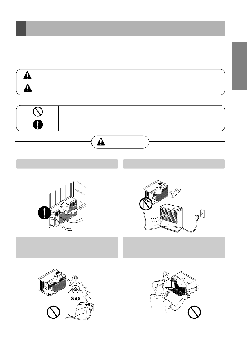
■ Installation
Always install the expansion panel(s).
• No installation may cause fire and electric
shock accident.
Do not place the power cord near a heater.
• It may cause fire and electric shock.
Do not use the power cord near flammable
gas or combustibles such as gasoline,
benzene, thinner, etc.
• It may cause explosion or fire.
Do not disassemble or modify products.
• It may cause failure and electric shock.
Gasolin
Safety Precautions
WARNING
CAUTION
Page 4
4 Room Air Conditioner
Safety Precautions
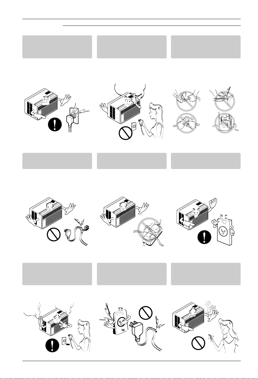
■ Operation
Plug in the power plug
properly.
• Otherwise, it will cause
electric shock or fire due to
heat generation or electric
shock.
Do not operate or stop the
unit by inserting or pulling
out the power plug.
• It will cause electric shock or
fire due to heat generation.
Do not damage or use an
unspecified power cord.
• It will cause electric shock or
fire.
Do not modify power cord
length.
• It will cause electric shock or
fire due to heat generation.
Do not share the outlet with
other appliances.
• It will cause electric shock or
fire due to heat generation.
Always plug into a
grounded outlet.
• No grounding may cause
electric shock (See
Installation Manual).
Unplug the unit if strange
sounds, odors, or smoke
come from it.
• Otherwise it may cause fire
and electric shock accident.
Do not use the socket if it is
loose or damaged.
• It may cause fire and electric
shock.
Do not operate with wet
hands or in damp
environment.
• It will cause electric shock.
ON
Page 5
Owner's Manual 5
Safety Precautions
ENGLISH
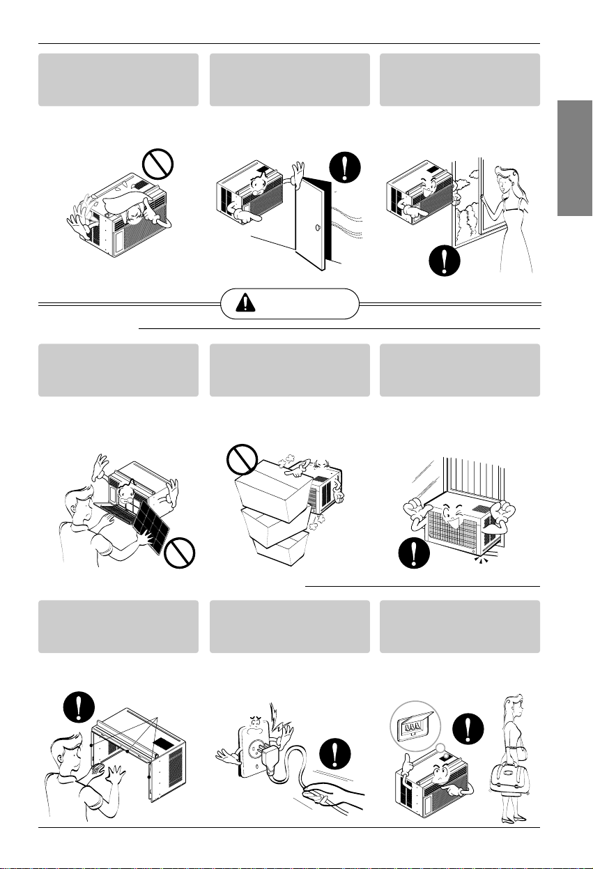
Do not allow water to run
into electric parts.
• It will cause failure of machine
or electric shock.
Leave the door closed while
the air conditioner is
running.
• It is not designed to cool the
entire house.
Ventilate before operating
air conditioner when gas
goes out.
• It may cause explosion, fire,
and burn.
Never touch the metal parts
of the unit when removing
the filter.
• They are sharp and may
cause injury.
Do not block the inlet or
outlet.
• It may cause failure of
appliance or accident.
Ensure that the outer case
is not damaged by age or
wear.
• If leaving appliance damaged,
there is concern of damage
due to the falling of product.
Be cautious not to touch the
sharp edges when
installing.
• It may cause injury.
Hold the plug by the head
when taking it out.
• It may cause electric shock
and damage.
Turn off the main power
switch when not using it for
a long time.
• Prevent accidental startup
and the possibility of injury.
CAUTION
■ Installation
Sharp
edges
■ Operation
Page 6
6 Room Air Conditioner
Safety Precautions
Do not place heavy object
on the power cord and take
care so that the cord should
not be pressed.
• There is danger of fire or
electric shock.
If water enters the product,
turn off the the power switch
of the main body of appliance.
Contact service center after
taking the power-plug out
from the socket.
Do not clean the air
conditioner with water.
• Water may enter the unit and
degrade the insulation. It may
cause an electric shock.
Turn off the power and
breaker firstly when
cleansing the unit.
• Since the fan rotates at high
speed during operation, it
may cause injury.
Do not put a pet or house
plant where it will be
exposed to direct air flow.
• This could injure the pet or
plant.
Do not use this appliance
for special purposes such
as pets, foods, precision
machinery, or objects of art.
• It is an air conditioner, not a
precision refrigeration system.
Always insert the filter
securely.
Clean it every two weeks.
• Operation without filters will
cause failure.
Use a soft cloth to clean. Do
not use wax, thinner, or a
strong detergent.
• The appearance of the air
conditioner may deteriorate,
change color, or develop
surface flaws.
Do not drink water drained
from air conditioner. / Do
not direct airflow at room
occupants only.
• It contains containments and
will make you sick. / This
could damage your health.
Wax
Thinner
Page 7

Owner's Manual 7
Safety Precautions
ENGLISH
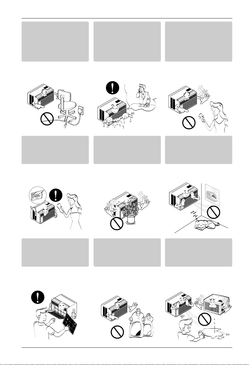
Preparing for operation
Contact an installation specialist for installation.
Plug in the power plug properly.
Do not share the same outlet with other appliances
Do not use an extension cord.
Do not start/stop operation by plugging/unplugging the power cord.
If cord/plug is damaged, replace only with an authorized part.
6
5
4
3
2
1
Usage
Cleaning and maintenance
Do not touch the metal parts of the unit when removing the filter. Injuries can occur when handling sharp
metal edges.
Do not use water to clean inside the air conditioner. Exposure to water can destroy the insulation, leading
to possible electric shock.
When cleaning the unit, first make sure that the power and breaker are turned off. The fan rotates at a
very high speed during operation. There is a possibility of injury if the unit’s power is accidentally
triggered on while cleaning inner parts of the unit.
3
2
1
Service
For repair and maintenance, contact your authorized service dealer.
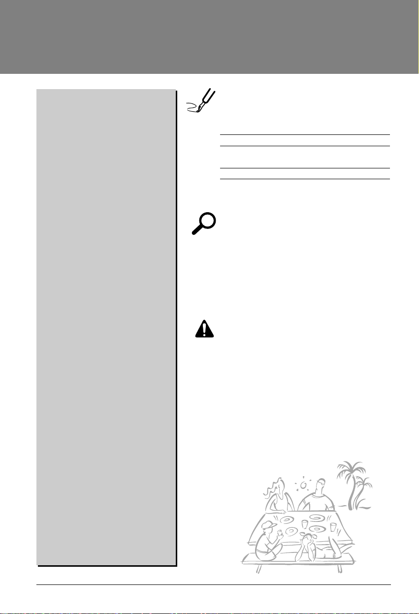
Being exposed to direct airflow for an extended period of time could be hazardous to your health. Do not
expose occupants, pets, or plants to direct airflow for extended periods of time.
Due to the possibility of oxygen deficiency, ventilate the room when using together with stoves or other
heating devices.
Do not use this air conditioner for non-specified special purposes (e.g. preserving precision devices,
food, pets, plants, and art objects). Usage in such a manner could harm such property.
3
2
1
Prior to Operation
Page 8
OPERATIONTHERMOSTAT
OFF
HIGH
COOL
MED
COOL
LOW COOL
MED
FAN
LOW
FAN
8 Room Air Conditioner
Operating Instructions
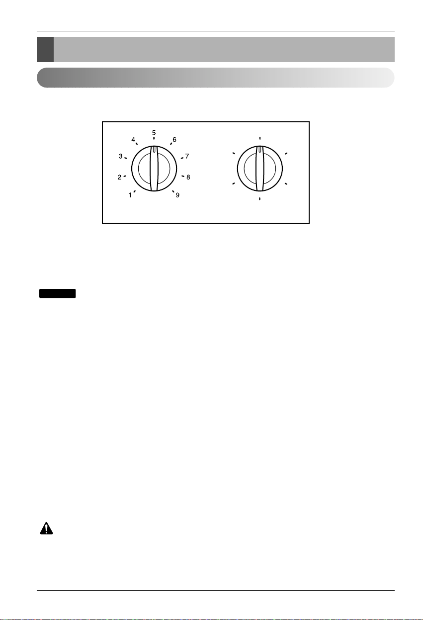
Location and Function of Controls
The controls will look like following picture.
■ OPERATION
High Cool, Med Cool and Low Cool provide cooling with different fan speeds. Med Fan or Low
Fan provides air circulation and filtering without cooling. Off turns the air conditioner off.
: If you move the switch from a cool setting to off or to a fan setting, wait at least 3 minutes
before switching back to a cool setting.
Cooling Descriptions
For Normal Cooling- Select High Cool or Med Cool with the Operation knob at the midpoint of
Thermostat knob.
For Maximum Cooling- Select High Cool with the Operation knob at the highest number
available on your Thermostat knob.
For Quieter & Nighttime Cooling- Select Low Cool with the Operation knob at the midpoint of
Thermostat knob.
■ THERMOSTAT
The THERMOSTAT is used to maintain the room temperature. The compressor will cycle on
and off to keep the room at the same level of comfort. When you turn the knob to a higher
number(the right side) and the indoor air will become cooler.
The 5 or 6 position (the middle position of arc) is a normal setting for average conditions.
CAUTION
: When the air conditioner has been performed its cooling operation and is turned off or set to
the fan position, wait at least 3 minutes before resetting to the cooling operation again.
NOTICE
Function of Controls
Page 9
Owner's Manual 9
Operating Instructions
ENGLISH
Power
Tem p
Fan Speed
Timer Mode
˚C
TIMER POWERMODE
TEMP
FAN
SPEED
F1 LOW
F2 MED
F3 HIGH
Dry Timer
Fan
Energy
Saver
Cool
1
2
6
3 45
1
2
3
4
5
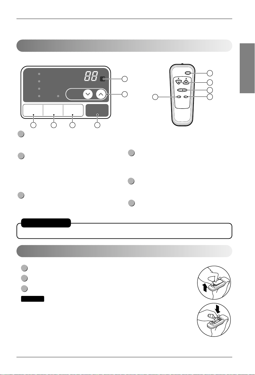
Push out the cover on the back of the remote control with your thumb
Pay attention to polarity and insert two new AAA 1.5V batteries.
Reattach the cover.
:
Do not use rechargeable batteries. Make sure that both batteries are new.
• In order to prevent discharge, remove the batteries from the remote control if the air
conditioner is not going to be used for an extended period of time
Keep the remote control away from extremely hot or humid places.
To maintain optimal operation of the remote control, the remote sensor should not be
exposed to direct sunlight.
• The remote control can be mounted on a wall using the mountable holder.
NOTICE
3
2
1
Inserting the Remote Control Batteries
POWER
Operation starts when this button is pressed and
stops when you press the button again.
TEMPERATURE CONTROL
The thermostat monitors room temperature to
maintain the desired temperature.
The thermostat can be set between 16°C~30°C.
The unit takes an average of 30 minutes to adjust
the room temperature by 1°C.
OPERATION MODE SELECTOR
Select cooling mode to cool the room.
Select energy saver mode for energy saving
operation.
Select fan mode for basic ventilating fan
operation.
Select dry mode for dry operation.
FAN SPEED SELECTOR
For increased power while cooling, select a
higher fan speed.
3 steps: High ➔ Low ➔ Med
ON/OFF TIMER
The timer can be set to start and stop the unit in
hourly increments (up to 12 hours).
REMOTE CONTROL SENSOR
6
5
4
3
2
1
Remote Control OperationsRemote Control Operations
AUTO RESTART
In failure of electric power, the unit runs as previous setting operation.
The remote control and control panel will look like those represented in the following pictures.
Page 10
10 Room Air Conditioner
Operating Instructions
VENTCLOSE
OPEN
Part
A
Vent Control
For maximum cooling efficiency, CLOSE the vent. This will allow internal air circulation.
OPENtheventtodischargestaleair.
Adjusting the Air Flow Direction
• Recommended orientation of louvers
Adjust louvers to face upwards when cooling to maximize cooling efficiency.
Airflow can be adjusted by changing the direction of the air conditioner's louvers. This can also increase the
cooling efficiency of the air conditioner.
: Before using the ventilation feature, position the vent lever by
pulling Part A out straight and snapping it into place.
NOTICE
Adjusting horizontal air flow Adjusting vertical air flow
• Adjusting Horizontal Air Flow Direction
Adjusting the vertical louvers left and right will
change horizontal airflow.
• Adjusting Vertical Air Flow Direction
Adjusting the horizontal vane up and down will
change vertical airflow. The vane can be adjusted
by nudging the vane backward or forward.
Adjusting the Air Flow Direction
Page 11
Owner's Manual 11
Care and Maintenance
ENGLISH
Drain pipe
Drain cap
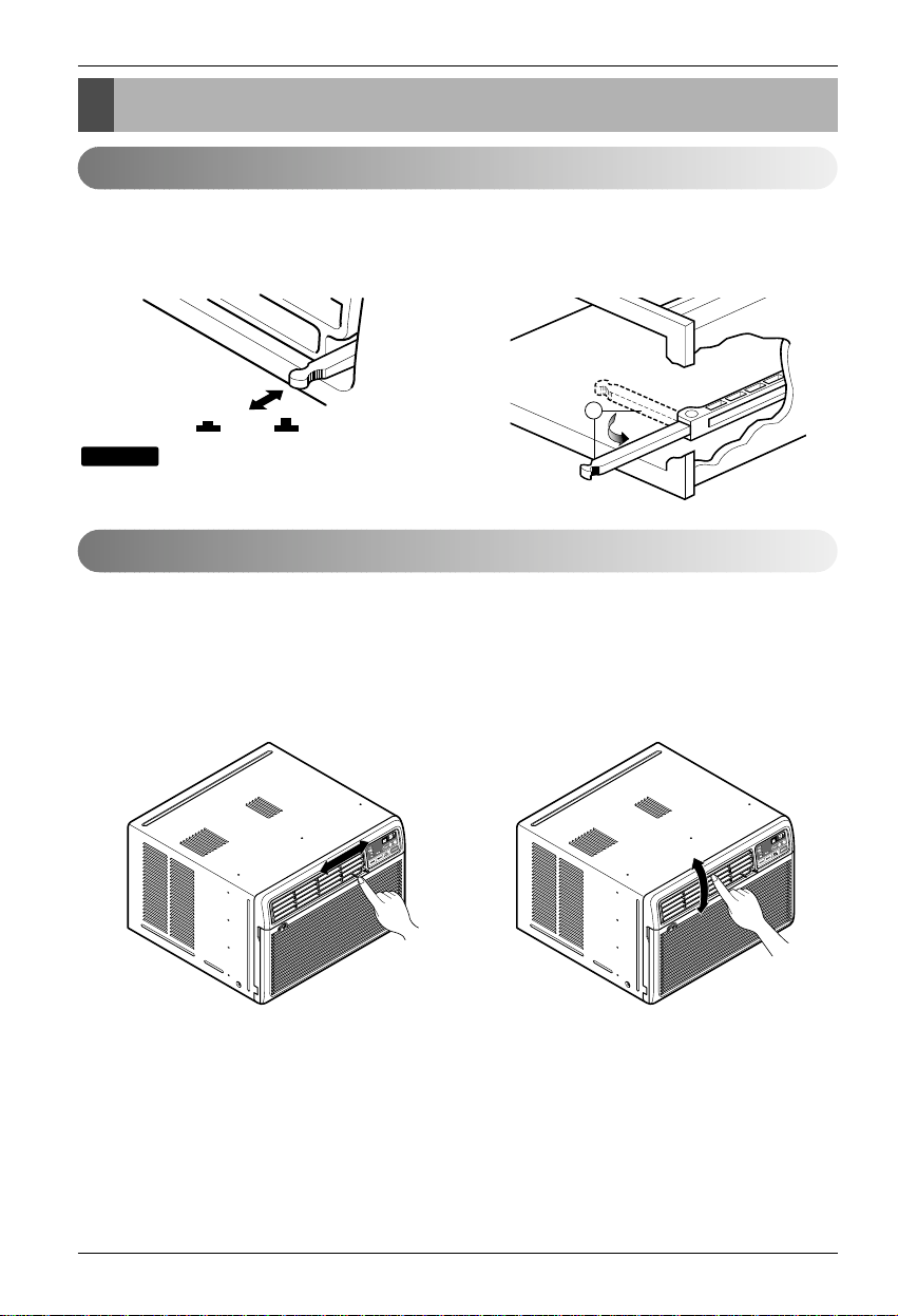
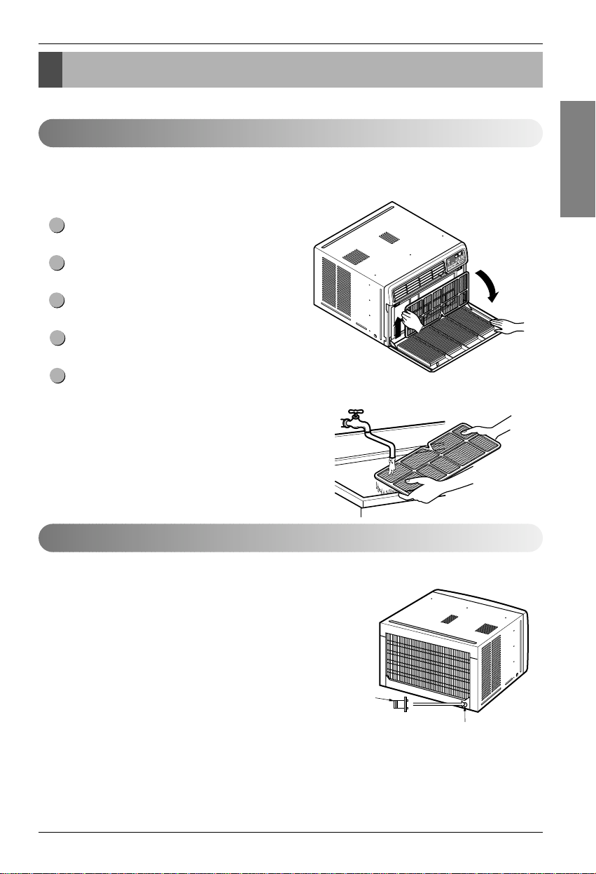
Turn the power off and unplug the power plug before cleaning the air conditioner.
Air Filter
The air filter behind the inlet grille should be checked and cleaned at least once every 2 weeks (or as
necessary) to maintain optimal performance of the air conditioner.
How to remove the air filter
The grille may be opened from the top for easy
maintenance after installation.
Open the inlet grille by pulling off the exposed door
on the top of the unit (based on installation).
Pull the tab slightly to release the filter. Pull the filter
in the same direction as the opening.
Clean the filter with warm, soapy water. The water
should be below 40°C (104°F).
Rinse off and gently shake off excess water from the
filter. Let it dry before replaceing it.
5
4
3
2
1
Drainage
The base pan may overflow due to high humidity. To drain the excess
water, remove the drain cap from the back of the unit and secure the
drainpipe.
When pressing the drainpipe into place, apply force in the direction
away from the fins to avoid injuring yourself.
Care and Maintenance
Page 12

12 Room Air Conditioner
Care and Maintenance
CABINET
DRAIN
PAN
DRAIN HOSE
SCREW
Take the drain pan which is located in the air
discharge.
Remove the hole rubber from the base-pan (for
some models).
Install the drain pan to the right corner of the
cabinet with 4 (or 2) screws.
Connect the drain hose of 3/5" inside diameter to
the outlet located at the bottom of the drain
pan.You can purchase the drain hose or tubing
locally to satisfy your particular needs. (Drain
hose is not supplied).
4
3
2
1
How to Attach Drain Pan (Optional)
The air conditioner employs a proper drain method whereby the condensed water (moisture removed from the
air) is drained to the outside.
In very humid weather, (and for reverse cycle models in the reverse mode) excessive condensate water removed
from the air may cause some water to collect. To remove this excess water you can install the drain pan as
detailed below.
Page 13
Owner's Manual 13
Hardware Installation
ENGLISH
B
A
Power cord
Power cord
4
6
5
8
1
2
3
13
15
11
14
12
10
9
7
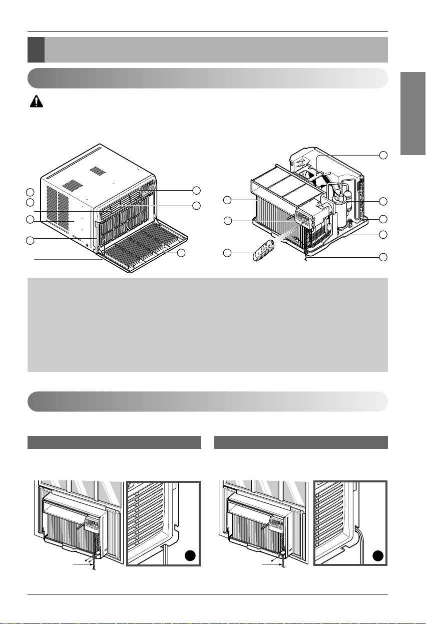
Product Features
1. CABINET
2. FRONT GRILLE
3. AIR FILTER
4. AIR INTAKE (INLET GRILLE)
5. AIR DISCHARGE
6. VERTICAL AIR DEFLECTOR
(HORIZONTAL LOUVER)
7. EVAPORATOR
8. HORIZONTAL AIR DEFLECTOR
(VERTICAL LOUVER)
9. CONTROL PANEL
10. POWER CORD
11. COMPRESSOR
12. BASE PAN
13. BRACE
14. CONDENSER
15. REMOTE CONTROLLER(OPTIONAL)
Remote Control Operations
Installing the Power cord
You can choose between two methods below according to your window stool shape and preference.
• Fasten the stopper using 2 screw holes, and lead
out the power cord through slit "A".
• Fasten the stopper using left screw hole, and rotate
properly to lead the power cord out through slit "B".
Using slit "A" Using slit "B"
CAUTION
: This appliance should be installed in accordance with national wiring regulations. The
following information serves acts as a guide to help to explain product features.
Hardware Installation
Page 14
14 Room Air Conditioner
Hardware Installation
About 1/2"
30"~60"
Awning
Cooled air
Fence
Over 20"
Heat
radiation
23" to 36"
Offset
1
/2" to 11/4"
Sill
Exterior
Interior wall
20
1
/12" min.
(Without frame curtain)
Stool
15" min
(With frame curtain)
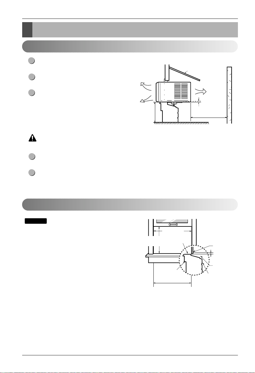
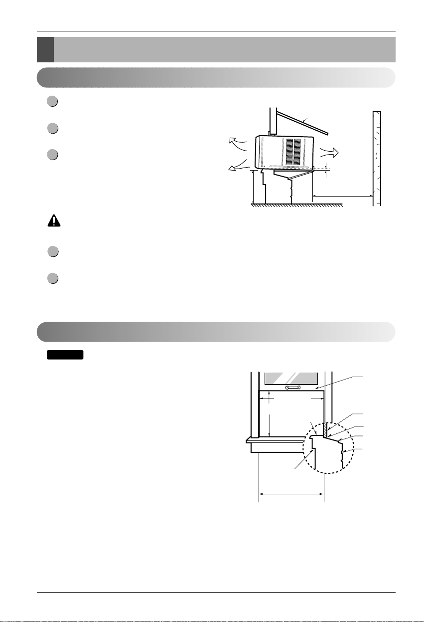
How to Install the Unit
To prevent vibration and noise, make sure the unit
is installed securely and firmly.
Install the unit where the sunlight does not shine
directly on the unit.
The outside of the cabinet must extend outward for
at least 12" and there should be no obstacles, such
as a fence or wall, within 20" from the back of the
cabinet because it will prevent heat radiation of the
condenser.
Restriction of outside air will greatly reduce the
cooling efficiency of the air conditioner.
CAUTION
: All side louvers of the cabinet must remain exposed to the outside of the structure.
Install the unit a little slanted so the back is slightly lower than the front (about 1/2").
This will force condensed water to flow to the outside.
Install the unit with the bottom about 30"~60" above the floor level.
5
4
3
2
1
Window Requirements
: All supporting parts should be secured to firm wood,
masonry, or metal.
• This unit is designed for installation in standard double
hung windows with actual opening widths from 23"
to 36".
• The top and bottom window sash must open sufficiently
to allow a clear vertical opening of 15" from the bottom
of the upper sash to the window stool.
NOTICE
WK Series
Page 15
Owner's Manual 15
Hardware Installation
ENGLISH
About 1/2"
30"~60"
Awning
Cooled air
Fence
Over 20"
Heat
radiation
27" to 39"
Offset
1
/2" to 11/4"
Sill
Exterior
Interior wall
23
5
/8" min.
(Without frame curtain)
Stool
16" min
(With frame curtain)
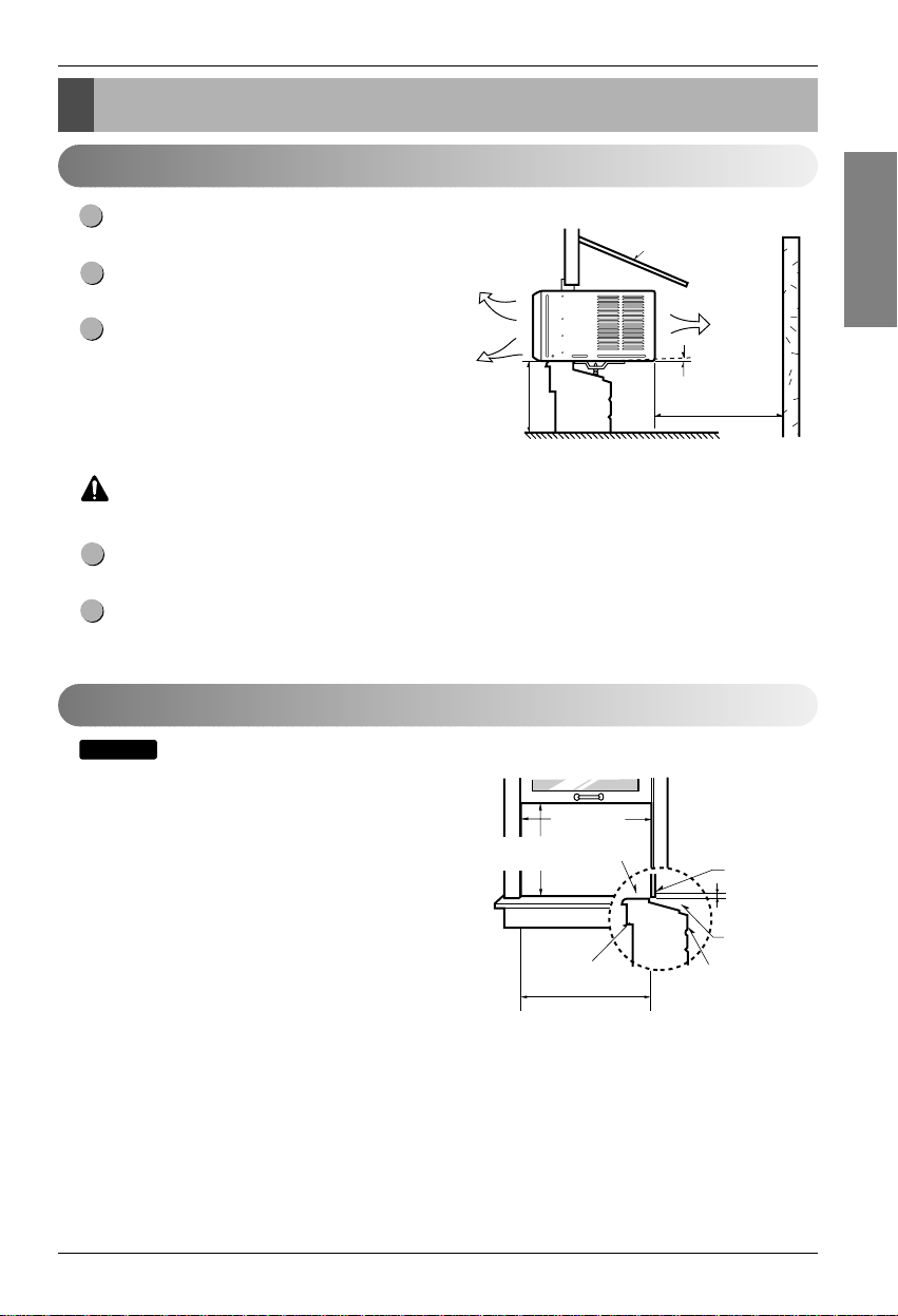
How to Install the Unit
To prevent vibration and noise, make sure the unit
is installed securely and firmly.
Install the unit where the sunlight does not shine
directly on the unit.
The outside of the cabinet must extend outward for
at least 12" and there should be no obstacles, such
as a fence or wall, within 20" from the back of the
cabinet because it will prevent heat radiation of the
condenser.
Restriction of outside air will greatly reduce the
cooling efficiency of the air conditioner.
CAUTION
: All side louvers of the cabinet must remain exposed to the outside of the structure.
Install the unit a little slanted so the back is slightly lower than the front (about 1/2").
This will force condensed water to flow to the outside.
Install the unit with the bottom about 30"~60" above the floor level.
5
4
3
2
1
Window Requirements
: All supporting parts should be secured to firm wood,
masonry, or metal.
• This unit is designed for installation in standard double
hung windows with actual opening widths from 27"
to 39".
• The top and bottom window sash must open sufficiently
to allow a clear vertical opening of 16" from the bottom
of the upper sash to the window stool.
NOTICE
WL Series
Page 16
16 Room Air Conditioner
Hardware Installation
About 1/2"
30"~60"
Awning
Cooled air
Fence
Over 20"
Heat
radiation
29" to 41"
18" min.
Inner sill
Offset
Window
Sash
Sill
Exterior
Interior wall
29" min.
(Without frame curtain)
How to Install the Unit
To prevent vibration and noise, make sure the unit
is installed securely and firmly.
Install the unit where the sunlight does not shine
directly on the unit.
There should be no obstacles, such as a fence and
wall, within 20" from the back of the cabinet
because it will prevent heat radiation of the
condenser.
Restriction of outside air will greatly reduce the
cooling efficiency of the air conditioner.
CAUTION
: All side louvers of the cabinet must remain exposed to the outside of the structure.
Install the unit a little slanted so the back is slightly lower than the front (about 1/2").
This will force condensed water to flow to the outside.
Install the unit with the bottom about 30"~60" above the floor level.
5
4
3
2
1
Window Requirements
: All supporting parts should be secured to firm wood, masonry, or metal.
• This unit is designed for installation in standard double
hung windows with actual opening widths from 29"
to 41".
• The top and bottom window sash must open sufficiently
to allow a clear vertical opening of 18" from the bottom
of the upper sash to the window stool.
NOTICE
WP Series
Page 17
Owner's Manual 17
Hardware Installation
ENGLISH
1
2 3 4
8 13
10
765
12
119
10
13
Shipping
Screws
(Type A)
(Type A)
5
11
11
5
5
Upper guide
Upper guide
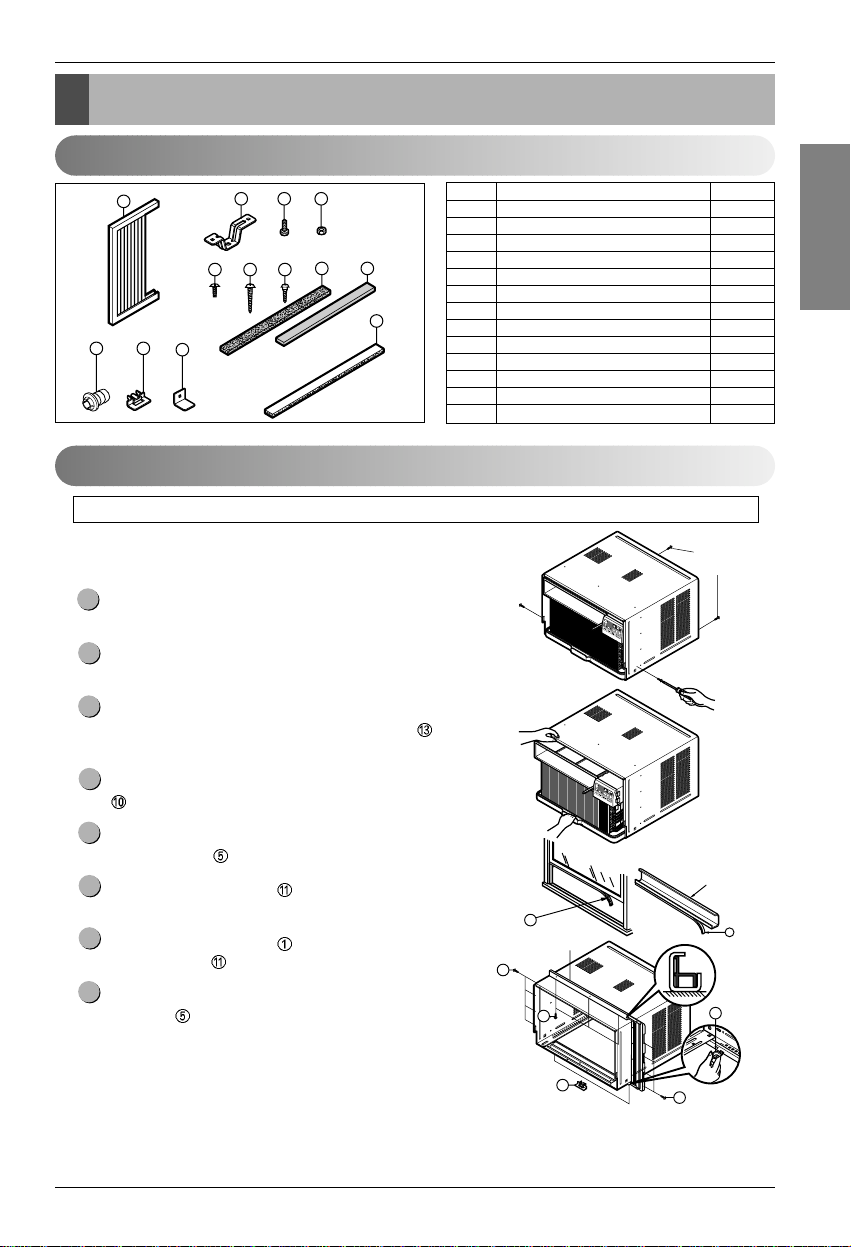
Installation Kits Contents
Suggested Tool Requirements
NO. NAME OF PARTS Q'TY
1 FRAME CURTAIN 2
2 SILL SUPPORT 2
3BOLT 2
4NUT 2
5 SCREW (TYPE A) 16
6 SCREW (TYPE B) 3
7 SCREW (TYPE C) 5
8FOAM-STRIP 1
9DRAINPIPE 1
10 FOAM-PE 1
11 FRAME GUIDE 2
12 WINDOW LOCKING BRACKET 1
13 FOAM-PE 1
PREPARATION OF CHASSIS
Remove the screws which fasten the cabinet at both
sides and at the back.
Slide the unit from the cabinet by gripping the base pan
handle and pulling forward while bracing the cabinet.
Cut the window sash seal to the proper length.
Peel off the backing and attach the Foam-PE
to the
underside of the window sash.
Remove the backing from the top upper guide Foam-PE
and attach it to the bottom of the Upper Guide.
Attach the upper guide onto the top of the cabinet with 3
Type A screws
.
Insert the Frame Guides into the bottom of the
cabinet.
Insert the Frame Curtain
into the Upper Guide and
Frame Guides .
Fasten the curtains to the unit with 4 Type
A screws .
8
7
6
5
4
3
2
1
SCREWDRIVER(Philips and Flatead), RULER, KNIFE, HAMMER, PENCIL, LEVEL
WK, WL Series
Page 18

18 Room Air Conditioner
Hardware Installation
Cabinet Installation
Open the window. Mark a line on center of the
window stool.
Carefully place the cabinet on the window stool and
align the center mark on the bottom front with the
center line marked in the window stool.
Pull the bottom window sash down behind the Upper
Guide until it meets.
: Do not pull the window sash down tightly that the
movement of Frame Curtain
is restricted.
Loosely assemble the Sill Support using the parts
in Fig. 3.
Select the position that will place the Sill Support
near the outer most point on sill (See Fig. 4)
: Be careful when you install the cabinet
(Frame Guides are broken easily).
Attach the Sill Support to the cabinet track hole in
relation to the selected position using 2 Type A
screws in each support (See Fig. 4).
5
NOTICE
4
3
NOTICE
2
1
INDOOR OUTDOOR
Sill Support
2
Nut
4
Bolt
3
INDOOR OUTDOOR
Cabinet
About
1
/2"
Frame Guide
11
Screw(Type A)
5
Upper Guide
Window stool
Front Angle
Window Sash Upper guide
Frame Curtain
1
Foam-pe
10
Foam-pe
13
Cabinet
Fig. 1
Fig. 2
Fig. 3
Fig. 4
Page 19

Owner's Manual 19
Hardware Installation
ENGLISH
Sash track
Front Angle
About
1
/2"
Screw(Type B)
6
Screw(Type B)
6
Sill Support
2
Sill Support
2
Foam-Strip
8
Fig. 5
Type C
7
Fig. 6
Screw(Type A)
Screw
(Type A)
Power cord
Fig. 7
Fig. 8
The cabinet should be installed with a very slight tilt
(about 1/2") downward toward the outside
(See Fig. 5).
Adjust the bolt and the nut of Sill Support for
balancing the cabinet.
Attach the cabinet to the window stool by driving
the screws
(Type B: Length 16mm (5/8 inch)
and below.) through the front angle into window
stool.
Pull each Frame Curtain
fully to each window
sash track, and repeat step 2.
Attach each Frame Curtain the window sash using
screws (TypeC). (See Fig. 6)
CAUTION
:
Donotdrillaholeinthebottompan.
The unit is designed to operate with
approximately 1/2" of water in bottom pan.
There is no need to add water if the
panisdry.
Slide the unit into the cabinet. (See Fig. 7)
CAUTION
:
For security purpose, reinstall screws
(Type A) at cabinet's sides.
Cut the Foam-Strip to the proper length and insert
between the upper window sash and the lower
window sash. (See Fig. 8)
11
10
9
8
7
6
Page 20

20 Room Air Conditioner
Hardware Installation
Attach the Window Locking Bracket withaType
C screw .(SeeFig.9)
Attach the front grille to the cabinet by inserting the
tabsonthegrilleintothetabsonthefrontofthe
cabinet. Push the grille in until it snaps into place.
(See Fig. 10)
Pull down the inlet grille and secure it with a Type
A screw
through the front grille. (See Fig. 11)
Window installation of room air conditioner is
now completed. See ELECTRICAL DATA for
attaching power cord to electrical outlet.
15
14
13
12
Window locking
bracket
12
Fig. 9
Fig. 10
Fig. 11
Page 21

Owner's Manual 21
Hardware Installation
ENGLISH
11
15
(Type A)
5
(Type A)
1 2 3 4 5
6 7 8 9 10 11
14 12 13
15
5
14
Shipping
Screws
Upper guide
Upper guide
Installation Kits Contents
Suggested Tool Requirements
NO. NAME OF PARTS Q'TY
1 FRAMECURTAIN 2
2 SUPPORTBRACKET 2
3 SILLBRACKET 2
4 LOCKNUT 4
5 SCREW(TYPE A) 14
6 SCREW(TYPE B) 7
7 SCREW(TYPE C) 5
8 SCREW(TYPE D) 2
9 CARRIAGEBOLT 2
10 FOAM STRIP 1
11 FOAM SEAL 1
12 WINDOW LOCKING BRACKET 1
13 DRAIN PIPE 1
14 FRAME GUIDE 2
15 FOAM-PE 1
PREPARATION OF CHASSIS
Remove the screws which fasten the cabinet at both
sides and at the back.
Slide the unit from the cabinet by gripping the base pan
handle and pulling forward while bracing the cabinet.
Cut the window sash seal to the proper length.
Peel off the backing and attach the Foam-Seal to the
underside of the window sash.
Remove the backing from the top upper guide Foam-PE
and attach it to the bottom of the Upper Guide.
Attach the upper guide onto the top of the cabinet with 3
Type A screws
.
Insert the Frame Guides into the bottom of the
cabinet.
Insert the Frame Curtain
into the Upper Guide and
Frame Guides .
Fasten the curtains to the unit with 10 Type
A screws
.
8
7
6
5
4
3
2
1
SCREWDRIVER(Philips and Flatead), RULER, KNIFE, HAMMER, PENCIL, LEVEL
WP Series
Page 22

22 Room Air Conditioner
Hardware Installation
3
9
2
6
3
15
11
2
4
Fig. 1
Fig. 2
Fig. 3
Fig. 4
Support
Bracket
Lock nut
Sill
Bracket
Carriage
Bolt
Front angle
W
indow stool
Window sash
Upper Guide
Cabinet
Foam
-Seal
Frame curtain
Foam-PE
(Type B)
Cabinet
Track hole
Support
Bracket
Carriage bolt
and lock nut
Machine screw(Type D)
and lock nut
Outer edge
of window
sill
Sill bracket
Upper
Guide
Cabinet Installation
Open the window. Mark a line on the center of the
window stool between the side window stop
moldings.
Loosely attach the sill bracket to the support
bracket using the carriage bolt and the lock nut.
Attach the sill bracket to the window sill using the
screws (Type B).
Carefully place the cabinet on the window stool
and align the center mark on the bottom front with
the center line marked window stool.
Using the M-screw and the lock nut, attach the
support bracket to the cabinet track hole. Use the first
track hole after the sill bracket on the outer edge of
the window sill. Tighten the carriage bolt and the lock
nut. Be sure the cabinet slants outward.
CAUTION
:
Do not drill a hole in the bottom pan.
The unit is designed to operate with
approximately 1/2" of water in bottom pan.
Pull the bottom window sash down behind the Top
retainer bar until they meet.
1. Do not pull the window sash down so tightly
that the movement of Frame curtain is restricted.
Attach the cabinet to the window stool by driving
the screws (Type B) through the cabinet into
window stool.
2. The cabinet should be installed with a very slight
tilt downward toward the outside.
NOTICE
4
3
2
1
Page 23

(Type C)
6
7
Fig. 5
Fig. 6
Fig. 7
Fig. 8
Fig. 9
Screw(Type B)
Front Angle
Sash track
Window locking
bracket
Foam-Strip
Owner's Manual 23
Hardware Installation
ENGLISH
Pull each Frame curtain fully to each window sash
track, and pull the bottom window sash down behind
the Top retainer bar until it meets.
Attach each Frame curtain the window sash by using
screws (Type C.) (See Fig. 6)
Slide the unit into the cabinet.(See Fig. 7)
CAUTION
:
For security purpose, reinstall
screws(Type A) at cabinet's sides.
Cut the Foam-strip to the proper length and insert
between the upper window sash and the lower
window sash.(See Fig. 8)
Attach the Window locking bracket with a screw
(Type C.) (See Fig. 9)
9
8
7
6
5
Screw
Power Cord
Screw
Page 24

24 Room Air Conditioner
Hardware Installation
Fig. 10
Attach the front grille to the cabinet by inserting the
tabs on the grille into the tabs on the front of the
cabinet. Push the grille in until it snaps into place.
(See Fig.10)
Lift the inlet grille and secure it with a screw (Type A)
through the front grille.(See Fig. 10)
Window installation of room air conditioner is now
completed. See ELECTRICAL DATA for attaching
power cord to electrical outlet.
12
11
10
Page 25

Electrical Safety
Owner’s Manual 25
Electrical Safety
Electrical Data
Use Wall Receptacle Power Supply
Standard 125V, 3-wire grounding
receptacle rated 15A, 125V AC
Standard 250V, 3-wire grounding
receptacle rated 15A, 250V AC
Use 15 AMP. time
delay fuse or 15 AMP.
circuit breaker.
Use 20 AMP. time
delay fuse or 20 AMP.
circuit breaker.
Standard 250V, 3-wire grounding
receptacle rated 20A, 250V AC
The shape may be different according to its model.
NOTICE
DO NOT USE AN EXTENSION CORD on 230, 208, and 230/208 Volt units.
All wiring should be made in accordance with local electrical codes and regulations.
Aluminum house wiring may pose special problems. Consult a qualified electrician.
NOTICE
Page 26

26 Room Air Conditioner
Electrical Safety
IMPORTANT
(PLEASE READ CAREFULLY)
FOR THE USER'S PERSONAL SAFETY,THIS
APPLIANCE MUST BE PROPERLY GROUNDED
The power cord of this appliance is equipped with a
three-prong (grounding) plug. Use this with a standard
three-slot (grounding) wall power outlet to minimize the
hazard of electric shock. The customer should have
the wall receptacle and circuit checked by a qualified
electrician to make sure the receptacle is properly
grounded.
DO NOT CUT OR REMOVE THE THIRD (GROUND)
PRONG FROM THE POWER PLUG.
A. SITUATIONS WHEN THE APPLIANCE WILL BE
DISCONNECTED OCCASIONALLY:
Because of potential safety hazards, we strongly
discourage the use of an adapter plug. However, if you
wish to use an adapter, a TEMPORARY
CONNECTION may be made. Use UL-listed adapter,
available from most local hardware stores.
The large slot in the adapter must be aligned with the
large slot in the receptacle to assure a proper polarity
connection.
:
Attaching the adapter ground terminal to the wall
receptacle cover screw does not ground the
appliance unless the cover screw is metal, and not
insulated, and the wall receptacle is grounded
through the house wiring. The customer should
have the circuit checked by a qualified electrician to
make sure the receptacle is properly grounded.
Disconnect the power cord from the adapter, using
one hand on each. Otherwise, the adapter ground
terminal might break. DO NOT USE the appliance with
a broken adapter plug.
B. SITUATIONS WHEN THE APPLIANCE WILL BE
DISCONNECTED OFTEN.
Do not use an adapter plug in these situations.
Unplugging the power cord frequently can lead to an
eventual breakage of the ground terminal. The wall
power outlet should be replaced by a three-slot
(grounding) outlet instead.
USE OF EXTENSION CORDS
Because of potential safety hazards, we strongly
discourage the use of an extension cord. However, if
youwishtouseanextensioncord,useaCSA
certified/UL-listed 3-wire (grounding) extension cord,
rated at 15A, 125V.
Electrical Safety
ENGLISH
Page 27

Owner's Manual 27
Common Issues
ENGLISH
Before calling for service, please review the following list of common problems and solutions.
The air conditioner is operating normally when:
• You hear a pinging noise. This is caused by water being picked up by the condenser on rainy days or in highly
humid conditions. This feature is designed to help remove moisture in the air and improve cooling efficiency.
• You hear the thermostat click. This is caused by the compressor cycle starting and stopping.
• You see water dripping from the rear of the unit. Water may be collected in the base pan in highly humid
conditions or on rainy days. This water overflows and drips from the rear of the unit.
• You hear the fan running while the compressor is silent. This is a normal operational feature.
The air conditioner may be operating abnormally when:
Problem Possible Causes What To Do
■ The air conditioner is unplugged or
not plugged in completely
■ The fuse is blown/circuit breaker is
triggered
■ Power failure.
■ Air flow is restricted
■ The THERMOSTAT may not be
set cool enough
■ The air filter is dirty.
■ The air conditioner was just
turned on.
■ Cold air is escaping.
■ Cooling coils are iced up
■ Thecoolingcoilsareicedover.
• Make sure the plug is completely plugged into
the outlet
• Check the fuse/circuit breaker box and replace
the fuse or reset the breaker
• In the event of a power failure, set the power
control to OFF. When the power is restored,
wait 3 minutes to restart the air conditioner to
prevent the compressor from overloading
• Make sure there are no curtains, blinds,
furniture or other obstacles in front of the air
conditioner
• Turn the knob to a higher setting. The highest
setting provides maximum cooling
• Clean the filter at least every 2 weeks. Refer to
the “Care and Maintenance” section (p.11) of
the manual.
• After the air conditioner is turned on, you need
to give the air conditioner some time to cool the
room.
• Check for open furnace floor resisters and cold
air returns.
• CLOSE the air conditioner vent
• See Ice appears on the air conditioner below
• Ice may block the air flow and obstruct the air
conditioner from properly cooling the room. Set
the fan at MED or HIGH while setting the
thermostat at 1 or 2 until the ice melts.
The air conditioner
does not operate
at all
Air conditioner
does not cool
Ice appears on the
air conditioner.
CommonProblemsandSolutions
Page 28

2 Climatiseur de Fenêtre
Manuel de l'utilisateur Climatiseur Type Fenêtre
TABLE DES MATIERES
POUR VOS ARCHIVES
Ecrivez le modèle et le numéro de série ci-après:
Modèle nº
Nº de série
Vous les trouverez sur une étiquette dans la partie
latérale de chaque unité.
Nom du revendeur
Date d'achat
■ Agrafez votre reçu à cette page au cas où vous en
auriez besoin pour prouver la date d'achat ou pour
vous prévaloir de la garantie.
LISSEZ CE MANUEL
Vous trouverez dedans plusieurs conseils utiles sur la
manière d'utiliser et d'entretenir correctement votre
climatiseur. Rien qu'un petit soin préventif de votre part
peut vous épargner une grande quantité de temps et
d'argent pendant la durée de vie de votre climatiseur.
Vous trouverez plusieurs réponses aux problèmes
communs dans la charte de conseils de dépannage. Si
vous lissez d'abord notre charte de Conseils de
dépannage, il est possible que vous n'ayez aucun
besoin d'appeler le service technique.
PRECAUTION
• Contactez un technicien agréé pour la réparation ou
maintenance de cette unité.
• Contactez un installateur pour l'installation de cette unité.
• Le climatiseur n'est pas destiné à l'usage de petits enfants
ou des handicapés sans surveillance.
• Les enfants doivent être surveillés afin de vous assurer
qu'ils ne jouent pas avec le climatiseur.
• Lorsque le cordon d'alimentation doit être remplacé, ce
travail de remplacement ne doit être confié qu'à du
personnelautoriséàl'aidedepiècesderechanged'origine.
• Le travail d'installation doit être réalisé conformément au
Code Electrique National, seulement par du personnel
qualifié et agréé.
P récautions.....................................3
Mode d'emploi................................8
Soins et entretien ........................11
Installation du matériel ...............13
Problèmes et solutions................27
Page 29

Manuel D'utilisation 3
Précautions
FRANÇAIS
Pour éviter des blessures à l'usager ou à d'autres personnes et des dommages à la propriété, vous
devez suivre les instructions ci-dessous.
■
L’utilisation incorrecte de l’appareil due à la méconnaissance des instructions de ce manuel provoquera des
blessures ou des dommages, dont la gravité est indiquée au moyen des symboles suivants.
Ce symbole représente la possibilité de mort ou de blessures graves.
Ce symbole indique la possibilité de blessures ou de dommages
uniquement à la propriété.
■ ß La signification des symboles utilisés dans ce manuel est indiquée ci-dessous.
Assurez-vous de ne pas faire.
Assurez-vous de suivre l'instruction.
■ Installation
Installez toujours le(s) panneau(x)
extensible(s).
• Ne pas l'installer peut provoquer un incendie
ou un incident de choc électrique.
N'utilisez pas le cordon d'alimentation près
d'un appareil de chauffage.
• Ceci peut provoquer un incendie ou un choc
électrique.
N'utilisez pas le cordon d'alimentation près de
substances inflammables ou combustibles,
comme essence, benzène, diluant, etc.
• Ceci peut provoquer une explosion ou un
incendie.
Ne démontez ni modifiez les produits.
• Ceci peut provoquer une défaillance de
l'appareil ou un choc électrique.
Gasolin
Précautions
Page 30

4 Climatiseur de Fenêtre
Précautions
■ Fonctionnement
Branchez correctement
cette unité sur une prise de
courant.
•
Autrement, ceci provoquera un
choc électrique ou un incendie
dû au dégagement de chaleur
ou un choc électrique.
Ne mettez en marche ni
arrêtez l'unité en branchant
ou débranchant la fiche
d'alimentation.
• Ceci risque de provoquer un
choc électrique ou un
incendie dû au dégagement
de chaleur.
N'utilisez pas de câbles
électriques endommagésou
non spécifiés
• Ceci risque de provoquer un
choc électrique ou un
incendie.
Ne modifiez pas la longueur
du cordon d'alimentation.
•
Ceci risque de provoquer un
choc électrique ou un incendie
dû au dégagement de chaleur.
Ne partagez pas la prise de
courant avec d'autres appareils.
•
Ceci risque de provoquer un
choc électrique ou un incendie
dû au dégagement de chaleur.
Branchez toujours cette unité
sur une prise reliée à la terre.
•
L'absence de mise à la terre peut
provoquer un choc électrique
(Voir le Manuel d'Installation).
Débranchez l'unité si elle
dégage de la fumée, des sons
ou des odeurs étranges.
• Ceci peut provoquer un
incendie et un incident de
choc électrique.
N'utilisez pas une prise de
courant desserréeou
endommagée.
• Ceci peut provoquer un
incendie et un choc
électrique.
N'utilisez pas cette unité
avec les mains humides ou
dans une ambiance humide.
• Ceci risque de provoquer un
choc électrique.
ON
Page 31

Manuel D'utilisation 5
Précautions
FRANÇAIS
Ne laissez pas que de l'eau
coulesurlespièces
électriques
• Ceci peut provoquer un
dysfonctionnement de l'appareil
ou un choc électrique.
Laissez la porte de la pièce
ferméelorsquele
climatiseur est en marche.
• Il n'est pas conçu pour refroidir la
maison toute entière.
S'ilyaeuunefuitedegaz,
aérez la pièce avant de mettre
en marche le climatiseur.
• Autrement, vous risquez de
provoquer une explosion, un
incendie ou des brûlures.
Ne touchez pas les composants
métalliques de l'unité lors de
l'enlèvement du filtre.
• Il y a des bords aiguisés pouvant
vous provoquer des blessures.
Ne bloquez pas la grille
d'entréeoudesortied'air.
• Ceci peut provoquer une
défaillance de l'appareil ou un
incident.
Assurez-vous que le boîtier
extérieur n'est pas endommagé
par son utilisation prolongée
ou par usure naturelle.
• Si vous laissez le support
extérieur endommagé, l'unité
pourrait tomber par terre et
s'abîmer.
Prenez soin de ne pas
toucher les bords aiguisés
lors de l'installation.
• Ceci peut provoquer des
blessures.
Prenez la fiche par sa tête
lorsque vous la débranchez.
• Autrement vous risquez de
provoquer un choc électrique et
des dommages.
Mettez l'interrupteur principal sur la
position arrêt(off)aucasoù le
climatiseur ne serait pas utilisé
pendant une longue période de temps.
• Ceci préviendra un démarrage
accidentel et de possibles
blessures.
■ Installation
Bords
aiguisés
■ Fonctionnement
Page 32

6 Climatiseur de Fenêtre
Précautions
Ne placez pas d'objets
lourds sur le cordon
d'alimentation et faites
attention à ce que le cordon
ne soit pas pressé.
• Ceci risquerait de provoquer un
incendie ou un choc électrique.
Si de l'eau entre à l'intérieur du
climatiseur, placez l'interrupteur
principal de l'appareil sur la
position arrêt(off).Aprèsavoir
débranché lafichedelaprise
de courant, contactez le centre
de service après-vente.
N'utilisez pas de l'eau pour
nettoyer le climatiseur.
• De l'eau pourrait entrer dans
l'unité et endommager l'isolement,
ce qui pourrait provoquer un choc
électrique.
Lorsdunettoyagedel'unité,
assurez-vous d'abord que
l'interrupteur et le disjoncteur
sont sur la position Arrêt(OFF).
• Autrement, vous pourriez vous
blesser, le ventilateur tournant à
une vitesse très forte lorsque
l'unité est en marche.
N’exposez pas un animal
domestique ou une plante
au flux direct de l'air.
• Ceci peut nuire à l'animal ou à la
plante.
N'utilisez pas cet appareil pour des
objectifs spéciaux comme pour
des animaux ou des plantes, des
dispositifs de précision, ou pour la
conservation d'objets d'art.
• C'est un climatiseur, non pas un
système de réfrigération de
précision.
Insérez toujours fermement
les filtres. Nettoyez-les
toutes les deux semaines.
• Faire marcher le climatiseur sans
filtres peut provoquer un
dysfonctionnement.
Utilisez un chiffon doux pour
le nettoyage. N'utilisez pas
de cire, de diluant ou de
détergents agressifs.
• L'aspect du climatiseur peut être
détérioré, la couleur peut changer
ou des imperfections peuvent
apparaître sur la surface.
Ne buvez pas l'eau drainéedu
climatiseur. / N'orientez pas le
flux d'air uniquement vers les
occupantsdelapièce.
• Elle contient des polluants et vous
rendra malade. Ceci peut nuire à
leur santé.
Wax
Thinner
Page 33

Manuel D'utilisation 7
Précautions
FRANÇAIS
Précédant la mise en service
Contactez un installateur professionnel pour l'installation.
Branchez correctement le cordon d'alimentation
Ne partagez pas la prise de courant murale avec un autre appareil.
N'utilisez pas un cordon prolongateur.
N'allumez pas et n'éteignez pas l'appareil en branchant et en débranchant le cordon d'alimentation.
Si le corde/bouchon est endommagé, remplace seulement avec une partie autorisée.
6
5
4
3
2
1
Utilisation
Nettoyage et entretien
Ne nettoyez pas l'intérieur de l'appareil avec de l'eau. L'eau peut détériorer l'isolation et entraîner la
possibilité de chocs électriques.
Éteignez toujours l'appareil avant de le nettoyer. La haute vitesse de rotation du ventilateur lors du
fonctionnement de l'appareil, peut causer des blessures. Il existe un fort risque de blessures si l'appareil
est accidentellement allumé lors du nettoyage des pièces internes de l'appareil.
2
1
Service
Contactez un centre de service accrédité pour l'entretien et la réparation.
L'exposition prolongéeaudébit d'air direct peut être dangereux pour la santé. N'exposez pas trop
longtemps les animaux ou les plantes au débit d'air direct.
Etant donné la possibilité de déficience d’oxygène, ventiler la pièce lors de l’utilisation simultanéede
poêles ou d’autres appareils de chauffage.
N'utilisez pas ce climatiseur à desfinsnonspécifiées (par exemple, conservation d'équipements de
précision, nourriture, animaux domestiques, plantes et objets d'art). Cette utilisation peut causer des
dommages matériels.
3
2
1
Précédent la mise en service
Page 34

OPERATIONTHERMOSTAT
OFF
HIGH
COOL
MED
COOL
LOW COOL
MED
FAN
LOW
FAN
8 Climatiseur de Fenêtre
Mode d'emploi
Fonctionnement de la télécommande
Les commandes ressembleront à I’une de celles-ci.
Remote Control OperationsCommandes
■ FONCTIONNEMENT
HIGH COOL (Froid Fort), MED COOL (Froid Moyen) et LOW COOL (Froid Léger) produisent du froid à
différentes vitesses de ventilateur. MED FAN (Ventilateur Moyen) ou LOW FAN (Ventilateur léger) font
circuler l’air et le filtrent sans le refroidir. OFF (Arrêt) éteint la climatisation.
: Si vous basculez l’interrupteur d’un réglage de refroidissement vers l’arrêt ou vers une commande de ventilateur,
attendez au moins 3 minutes avant de le re basculer sur un réglage de refroidissement.
Descriptions de refroidissements
Pour le Normal Cooling (Refroidissement normal) - Sélectionnez High Cool (Froid Fort) ou Med Cool
(Froid Moyen) avec le bouton Operation (Fonctionnement) au milieu du bouton Thermostatique.
Pour un Maximum Cooling (Refroidissement maximal) - Sélectionnez High Cool (Froid Fort) avec le
bouton Operation (Fonctionnement) surlechiffreleplusélevé de votre bouton Thermostatique
Pour le Quieter & Nighttime Cooling (Refroidissement plus silencieux et nocturne) - Sélectionnez Low
Cool (Froid léger) avec le bouton Operation (Fonctionnement) au milieu du bouton Thermostatique.
■ THERMOSTAT
Le THERMOSTAT sert à maintenir la température de la pièce. Le compresseur mettra en marche et arrêtera
le cycle pour garder le même niveau de confort dans la pièce. Quand vous tournez le bouton sur un chiffre
supérieur (côté droit), l’airdelapièce se refroidira.
La position 5 ou 6 (aumilieudel’arc) est le réglage normal pour des conditions moyennes.
PRECAUTION
: Lorsque vous éteignez la climatisation alors qu’elle travaille en mode refroidissement ou qu’elle est régléesur
la position ventilateur (fan), attendez au moins 3 minutes avant de déclencher de nouveau le mode
refroidissement.
REMARQUE
Page 35

Manuel D'utilisation 9
Mode d'emploi
FRANÇAIS
Retirez le couvercle situéàl'arrière de la télécommande avec votre pouce.
Notez la polarité des piles et insérez deux piles AAA 1,5V neuves.
Replacez le couvercle.
:
N'utilisez pas de piles rechargeables. Remplacez les deux piles à la fois.
• Si vous ne prévoyez pas utiliser le climatiseur pour une longue période de temps, retirez les
pilesdelatélécommande. Assurez-vous de remiser la télécommande à l'écart des endroits
excessivement chauds ou humides. Pour vous assurer du meilleur rendement possible de
votre télécommande, protégez le capteur de télécommande des rayons directs du soleil.
• Votre télécommande peut être monté au mur à l'aide du dispositif spécial de support.
REMARQUE
3
2
1
Remplacement des piles de la télécommande
POWER
Appuyez sur cette touche pour activer l'appareil et appuyez
de nouveau pour le désactiver.
CONTRÔLE DE TEMPÉRATURE
Le thermostat surveille la température de la pièce afin d'y
maintenir la température souhaitée.
Vous pouvez régler le thermosat entre 16°C~30°C.
Cet appareil ne requiert qu'environ 30 minutes pour
changer la température de la pièce de 1°C.
SÉLECTEUR DE MODE DE FONCTIONNEMENT
Rafraîchissez la pièce à l'aide du mode de refroidissement.
Pour le fonctionnement en mode d'économie énergétique,
sélectionnez le mode économiseur d'énergie.
Pour le fonctionnement normal du ventilateur, sélectionnez
le mode ventilateur.
Pour la déshumidification, sélectionnez le mode sans
humidité.
SÉLECTEUR DE RÉGIME DU VENTILATEUR
Pour un refroidissement accru, réglez le ventilateur à un
régime supérieur.
3 niveaux : High → Low → Med
MINUTERIE ACTIVATION/DÉSACTIVATION
La minuterie peut être réglée pour l'activation/désactivation
de l'appareil à intervalles de une heure (jusqu'à 12 heures).
CAPTEUR DE SIGNAL DE TÉLÉCOMMANDE
6
5
4
3
2
1
Remote Control OperationsFonctionnement de la télécommande
AUTO-REMISE EN MARCHE
En cas de manque de courant, l’unité reprend ses réglages précédents de fonctionnement.
La télecommande et le panneau de côntrole présenteront un aspect similaire à celui qui apparaisse dans
la photo ci-dessous.
Power
Tem p
Fan Speed
Timer Mode
˚C
TIMER POWERMODE
TEMP
FAN
SPEED
F1 LOW
F2 MED
F3 HIGH
Dry Timer
Fan
Energy
Saver
Cool
1
2
6
3 45
1
2
3
4
5
Page 36

10 Climatiseur de Fenêtre
Mode d'emploi
FERMÉ VENTILATION OUVERT
Pièce
A
Commande de l’orifice de ventilation
Pour une efficacité maximum du refroidissement, fermez l'ORIFICE DE VENTILATION. Ceci activera la
circulation de l'air de la pièce. OUVREZ l'orifice de ventilation afin d'évacuer l'air vicié.
Réglage de l’orientation du débit d’air
Vous pouvez régler le débit d'air en changeant l'orientation des volets du climatiseur. Cela peut également
améliorer l'efficacité de refroidissement du climatiseur.
• Orientation recommandéedesvolets
En mode refroidissement et afin d'en améliorer le rendement, orientez les volets vers le haut.
: Avant d'utiliser le dispositif de ventilation, positionnez le levier de
commande en tirant tout droit sur la pièce A et en la cliquant en place.
REMARQUE
Réglage du débit d'air horizontal Réglagedu débit d'air vertical
•
Réglage de l'orientation horizontale du débit d'air
Le réglage des volets verticaux vers la gauche et la
droite changera l'orientation du débit d'air
horizontal.
• Réglage de l'orientation verticale du débit d'air
Le réglage du déflecteur d'air horizontal vers le haut
et le bas changera l'orientation du débit d'air
vertical. L’ailette peut être ajustée en poussant
celle-ci vers la partie de devant ou vers l’arrière.
Réglage de l'orientation du débit d'air
Page 37

Manuel D'utilisation 11
Soins et entretien
FRANÇAIS
Tuyau de
drainage
Bouchon de drainage
Avant de nettoyer le climatiseur, éteignez-le et débranchez la fiche d'alimentation.
Filtre à air
Afin de maintenir l'efficacité du climatiseur à son meilleur niveau, vous devriez nettoyer le filtre à air, situé en
arrière de la grille de prise d'air, au moins à toutes les deux semaines (ou au besoin).
Comment retirer le filtre à air
Dans le but de faciliter l'entretien, la grille s'ouvre
par le haut.
Ouvrez la grille de prise d'air en retirant la porte
exposée sur la partie supérieure de l'appareil (en
fonction de l'installation).
Libérez le filtre à air en tirant légèrement sur la
languette. Tirez le filtre dans la direction de
l'ouverture.
Nettoyez le filtre à air dans de l'eau tiède
savonneuse. La température de l'eau doit être
inférieure à 40°C(104°F).
Rincez et essorez délicatement le filtre à air.
Laissez-le sécher avant de le réinstaller.
5
4
3
2
1
Drainage
Le réceptacle d'eau peut déborder selon le taux d'humidité.Pour
évacuer l'excédent d'eau, retirez le bouchon de drainage situéà
l'arrière de l'appareil et installez le tuyau de drainage.
En installant le tuyau de drainage, appliquez la pression dans le sens
opposé des ailettes de refroidissement de manière à ne pas vous
blesser.
Soins et entretien
Page 38

12 Climatiseur de Fenêtre
Soins et entretien
BOÎTIER
BAC DE
DRAINAGE
TUYAU
DE DRAINAGE
VIS
Prenez le bac de drainage, lequel se trouve
dans la décharge d’air.
Enlevez le bouchon de caoutchouc du bac de
récupération (dans certains modèles).
Installez le bac de drainage au coin droit du
boîtier à l’aide de 4 (ou 2) vis.
Raccordezletuyaudedrainagede3/5” de
diamètre interne à la sortie placée dans la partie
inférieure du bac de drainage. Vous pouvez
commander le tuyau de drainage ou l’acheter
sur place pour satisfaire vos besoins particuliers
(le tuyau de drainage n’est pas fourni).
4
3
2
1
Ce climatiseur emploie la méthode de drainage correcte, grâce à laquelle l’eau condensée(del’humiditéenlevée
de l’air) est drainéeversl’extérieur.
Dans des climats très humides, (et pour les modèles de cycle inversé en mode inversé) une quantité excessive
d’eau condensée enlevéedel’air peut produire un peu d’eau à contenir. Pour enlever cet excèsd’eau, vous
pouvez installer le bac de drainage comme il est expliqué par la suite.
Comment Raccorder le Bac de Drainage(Optionnel)
Page 39

Manuel D'utilisation 13
Installation du matériel
FRANÇAIS
B
A
4
6
5
8
1
2
3
13
15
11
14
12
10
9
7
Cordon
d'alimentation
Cordon
d'alimentation
Caractéristiques particulières de l’appareil
1. BOÎTIER
2. GRILLE AVANT
3. FILTRE À AIR
4. PRISE D'AIRAIR (GRILLE DE PRISE
D'AIR)
5. RETOUR D'AIR
6. DÉFLECTEUR D'AIR VERTICAL
(VOLET HORIZONTAL).
7. ÉVAPORATEUR
8. DÉFLECTEUR D'AIR HORIZONTAL
(VOLET VERTICAL)
9. PANNEAU DE COMMANDE
10. CORDON D'ALIMENTATION
11. COMPRESSEUR
12. RÉCEPTACLE D'EAU
13. ÉQUERRE DE RENFORT
14. CONDENSEUR
15. TÉLÉCOMMANDE(FACULTATIF)
Installer le cordon d’alimentation
Vous pouvez choisir entre deux méthodes ci-dessous selon votre forme et préférencedesellesdefenêtre.
• Attachez le taquet en utilisant 2 trous de vis, et
sortez le cordon d’alimentation de la fente "A".
• Attachez le taquet en utilisant le trou gauche de vis,
et tournez correctement pour sortir le cordon
d’alimentation de la fente "B".
Utilisant la fente "A" Utilisant la fente "B"
PRECAUTION
: Cet appareil doit être installé en fonction des normes électriques locales, régionales et nationales.
L’information suivante sert comme guide pour expliquer les caractéristiques du produit.
Installation du matériel
Page 40

14 Climatiseur de Fenêtre
Installation du matériel
Environ 1/2" (1,27 cm)
30"~60"
Auvent
Air refroidi
Clôture
20" (51 cm) ou plus
Radiation
de chaleur
23" à 36"
Décalage
1
/2" to 11/4"
Seuil
Extérieur
Mur intérieur
20
1
/12" min.
(Sans volets d'étanchéité)
Rebord
15"min.
(volet d'étanchéité inclus)
Installation de l’appareil
Installez l'appareil solidement et sécuritairement de
manière à prévenir la présence de vibrations et bruits.
Installez l'appareil de manière à ne pas l'exposer
directement aux rayons du soleil.
Le boîtier doit sortir d'au moins 12" à l'extérieur et
aucunobstacledugenreclôture ou mur doit se
situer à moins de 20" de l'arrière du boîtier car cela
nuira à la radiation de chaleur du condenseur. La
capacité de refroidissement du climatiseur sera
sérieusement affectée par une restriction
d'alimentation d'air extérieur.
PRECAUTION
: Toutes les ailettes latérales du boîtier doivent se situer à l'extérieur du bâtiment.
Installez l'appareil légèrement incliné vers l'extérieur (environ 1/2" [1,27 cm]).
Cela permettra à l'eau de condensation de s'écouler vers l'extérieur.
Installez l'appareil de manière à ce que sa surface inférieure se situe entre 30" et 60" (76 et 152 cm)
au-desssus du niveau du plancher.
5
4
3
2
1
Dimensions de fenêtre minimales
: Tous les éléments d'installation doivent être fixés à du bois,
de la maçonnerie ou du métal sain et solide.
• Cet appareil est conçu pour installation dans des
fenêtres à guillotine normales de largeur variant entre
23" et 36".
• Les châssis supérieur et inférieurdelafenêtre doivent
offrir une ouverture verticale d'au moins 15" entre le
bas du châssis supérieur et le rebord de la fenêtre.
REMARQUE
WK Feuilleton
Page 41

Manuel D'utilisation 15
Installation du matériel
FRANÇAIS
Environ 1/2" (1,27 cm)
30"~60"
Auvent
Air refroidi
Clôture
20" (51 cm) ou plus
Radiation
de chaleur
27" à 39"
Décalage
1
/2" to 11/4"
Seuil
Extérieur
Mur intérieur
23
5
/8" min.
(Sans volets d'étanchéité)
Rebord
16"min.
(volet d'étanchéité inclus)
Installation de l’appareil
Installez l'appareil solidement et sécuritairement de
manière à prévenir la présence de vibrations et bruits.
Installez l'appareil de manière à ne pas l'exposer
directement aux rayons du soleil.
Le boîtier doit sortir d'au moins 12" à l'extérieur et
aucun obstacle du genre clôture ou mur doit se
situer à moins de 20" de l'arrière du boîtier car cela
nuira à la radiation de chaleur du condenseur. La
capacité de refroidissement du climatiseur sera
sérieusement affectée par une restriction
d'alimentation d'air extérieur.
Installez l'appareil légèrement incliné vers l'extérieur (environ 1/2" [1,27 cm]).
Cela permettra à l'eau de condensation de s'écouler vers l'extérieur.
Installez l'appareil de manière à ce que sa surface inférieure se situe entre 30" et 60" (76 et 152 cm)
au-desssus du niveau du plancher.
5
4
3
2
1
Dimensions de fenêtre minimales
:
Tous les éléments d'installation doivent être fixés à du bois,
de la maçonnerie ou du métal sain et solide.
• Cet appareil est conçu pour installation dans des
fenêtres à guillotine normales de largeur variant entre
27" et 39".
• Les châssis supérieur et inférieur de la fenêtre doivent
offrir une ouverture verticale d'au moins 16" entre le
bas du châssis supérieur et le rebord de la fenêtre.
REMARQUE
PRECAUTION
: Toutes les ailettes latérales du boîtier doivent se situer à l'extérieur du bâtiment.
WL Feuilleton
Page 42

16 Climatiseur de Fenêtre
Installation du matériel
29" à 41"
Rebord
Décaler
Décalage
Sash
Seuil
Extérieur
Mur intérieur
Environ 1/2"
30"~60"
Auvent
Air refroidi
Clôture
20" ou plus
Radiation
de chaleur
29" min.
(Sans volets d'étanchéité)
18" min.
(volet d'étanchéité inclus)
Installation de l’appareil
Installez l'appareil solidement et sécuritairement de
manière à prévenir la présence de vibrations et bruits.
Installez l'appareil de manière à ne pas l'exposer
directement aux rayons du soleil.
Le boîtier doit sortir d'au moins 12" à l'extérieur et
aucunobstacledugenreclôture ou mur doit se
situer à moins de 20" de l'arrière du boîtier car cela
nuira à la radiation de chaleur du condenseur. La
capacité de refroidissement du climatiseur sera
sérieusement affectée par une restriction
d'alimentation d'air extérieur.
PRECAUTION
:
Toutes les ailettes latérales du boîtier doivent se situer à l'extérieur du bâtiment.
Installez l'appareil légèrement incliné vers l'extérieur (environ 1/2" [1,27 cm]).
Cela permettra à l'eau de condensation de s'écouler vers l'extérieur.
Installez l'appareil de manière à ce que sa surface inférieure se situe entre 30" et 60" au-desssus du
niveau du plancher.
5
4
3
2
1
Dimensions de fenêtre minimales
:
Tous les éléments d'installation doivent être fixés à du bois,
de la maçonnerie ou du métal sain et solide.
• Cet appareil est conçu pour installation dans des fenêtres
à guillotine normales de largeur variant entre 29" et 41".
• Les châssis supérieur et inférieurdelafenêtre doivent
offrir une ouverture verticale d'au moins 18" entre le bas
du châssis supérieur et le rebord de la fenêtre.
REMARQUE
WP Feuilleton
Page 43

Manuel D'utilisation 17
Installation du matériel
FRANÇAIS
1
2 3 4
8 13
10
765
12
119
10
13
5
11
11
5
5
(TYPE A)
(TYPE A)
Vis
d'expédition
Rail de
guidage supérieur
Rail de guidage supérieur
Contenu du nécessaire d’installation
Outils recommandés
NO. NOM DES PIÈCES QTÉ
1VOLETD'ÉTANCHÉITÉ 2
2 SUPPORT DE SEUIL 2
3BOULON 2
4 ÉCROU 2
5VIS(TYPEA) 16
6VIS(TYPEB) 3
7VIS(TYPEC) 5
8 BANDE EN MOUSSE 1
9 TUYAU DE DRAINAGE 1
10 JOINT D'ÉTANCHÉITÉ EN MOUSSE 1
11 DISPOSITIF DE GUIDAGE DU CADRE 2
12 ÉTRIERDEVERROUILLAGEDEFENÊTRE 1
13 JOINT D'ÉTANCHÉITÉ EN MOUSSE 1
PRÉPARATION DU CADRE
Déposez les vis situées de part et d'autre et à l'arrière du
boîtier.
Tout en retenant le boîtier, glissez l'appareil hors du
boîtier en tirant vers l'avant sur la poignéeduréceptacle
d'eau.
Coupez le joint d'étanchéité en mousse à la longueur
requise. Pelez le ruban détachable du joint et collez-le
surlafaceinférieur du châssis inférieur.
Pelez le ruban détachable du joint d'étanchéité en
mousse
du rail de guidage supérieur et collez-le sur la
face inférieure du rail de guidage supérieur.
À l'aide de trois vis de type A
, fixez le rail de guidage
supérieur sur le dessus du boîtier.
Insérez les dispositifs de guidage du cadre dans la
partie inférieure du boîtier.
Insérez les volets d'étanchéité dans le rail de guidage
supérieur et dans les dispositifs de guidage du cadre .
Fixez les volets d'étanchéitéàl'appareil à l'aide de
quatre vis de type A .
8
7
6
5
4
3
2
1
TOURNEVIS (Philips etT Flatead), RÈGLE, COUTEAU, MARTEAU, CRAYON, NIVEAU.
WK, WL Feuilleton
Page 44

18 Climatiseur de Fenêtre
Installation du matériel
INTÉRIEUR EXTÉRIEUR
Support de seuil
2
Écrou
4
Boulon
3
INTÉRIEUR EXTÉRIEUR
Boîtier
Environ 1/2" (1,27 cm)
Dispositif de
guidage de cadre
11
Vis (Type A)
5
Rail de guidage
supérieur
Rebord de fenêtre
Angle avant
Châssis de fenêtre
Rail de guidage supérieur
Volet d'étanchéité
1
Joint d'étanchéité
en mousse
10
Joint d'étanchéité
en mousse
13
Boîtier
Fig. 1
Fig. 2
Fig. 3
Fig. 4
Installation du boîtier
Ouvrez la fenêtre. Tracez une ligne au centre du
rebord de fenêtre.
Placez le boîtier soigneusement sur le rebord de
fenêtreetalignezlerepère central de sa portion
inférieure avant avec la ligne tracée sur le rebord de
fenêtre.
Abaissez le châssis inférieur à l'arrière du rail de
guidage supérieur jusqu'à ce qu'ils fassent
: Ne serrez pas le châssis de fenêtre au point où cela
nuira au mouvement des volets d'étanchéité
.
Assemblez le support de seuil
à l'aide des pièces
illustrées dans la fig. 3 mais ne les serrez pas. 3.
Choisissez l'emplacement qui situera le support de
seuil
à l'emplacement le plus à l'extérieur du seuil
(Voyez la fig. 4).
: Installez le boîtier avec précaution (les dispositifs
de guidage de cadre
peuvent briser).
Fixez les supports de seuil aux orifices de guidage
du boîtier,enfonctiondel'emplacementsélectionné,
à l'aide de 2 vis de type A pour chaque support
(Voyez la fig.4).
5
REMARQUE
4
3
REMARQUE
2
1
Page 45

Manuel D'utilisation 19
Installation du matériel
FRANÇAIS
Coulisse
de chassis
Angle avant
Environ
1
/2"
Vis (Type B)
6
Vis (Type B)
6
Support de seuil
2
Support de seuil
2
Bande
en mousse
8
Fig. 5
Type C
7
Fig. 6
Fig. 7
Fig. 8
Vis (Type A)
Cordon
d'alimentation
Vis (Type A)
Installez le boîtier avec une inclinaison d'environ
1/2" (1,27 cm) vers l'extérieur (Voyez la fig. 5).
Réglez l'écrou et le boulon des supports de seuil
de manière àéquilibrer le boîtier.
Fixez le boîtier au rebord de fenêtre à l'aide de
vis de type B
(16 mm [5/5"] de long) passant à
travers de l'angle avant du boîtier et se logeant
dans le rebord de fenêtre.
Tirez chaque volet d'étanchéité entièrement
contre chaque coulisse de châssis et répétez
l'étape 2.
Fixez chaque volet d'étanchéité à la coulisse de
châssis à l'aide de vis de type C .(Voyezlafig.6.)
PRECAUTION
:
Ne percez pas de trous dans le réceptacle d'eau.
L'appareil est conçu pour fonctionner avec environ
1/2" (1,27 cm) d'eau présent dans le réceptacle d'eau.
S'il n'y a pas d'eau dans le réceptacle, il n'est pas
nécessaire d'en ajouter.
Glissez l'appareil dans le boîtier.(Voyezlafig.7)
PRECAUTION
: Pour des raisons de sécurité,réinstallez les vis
latérales (Type A) du boîtier.
Coupez la bande en mousse à la longueur
appropriéeetinsérez-la entre les châssis supérieur
et inférieurdelafenêtre.(Voyez la fig. 8)
11
10
9
8
7
6
Page 46

20 Climatiseur de Fenêtre
Installation du matériel
Étrier de verrouillage
de fenêtre
12
Fig. 9
Fig. 10
Fig. 11
Fixez l'étrier de verrouillage de fenêtre à l'aide
d'une vis de type C
. (Voyez la fig. 9)
Fixez la grille avant au boîtier en en insérant les
languettes de la grille dans les encoches situées à
l'avant du boîtier. Poussez la grille jusqu'à ce que
vous l'entendiez cliquer en place. (Voyez la fig.10)
Abaissezlagrilledeprised'airetetfixez-laà l'aide
d'une vis de Type A
passant à travers de la
grille. (Voyez la fig. 11)
L'installation du climatiseur de pièce est
maintenant complétée. Pour les détails de
branchement du cordon d'alimentation à une
prise de courant murale, veuillez vous reporter
à SPÉCIFICATIONS ÉLECTRIQUES.
15
14
13
12
Page 47

Manuel D'utilisation 21
Installation du matériel
FRANÇAIS
11
15
Vis
d'expédition
(Type A)
5
(Type A)
1 2 3 4 5
6 7 8 9 10 11
14 12 13
15
5
14
Rail de
guidage supérieur
Rail de guidage supérieur
Contenu du nécessaire d’installation
Outils recommandés
NO. NOM DES PIÈCES QTÉ
1VOLETD'ÉTANCHÉITÉ 2
2 SUPPORT DE FIXATION 2
3 SUPPORT DE L'APPUI-FENÉTRE 2
4 ÉCROU 4
5 VIS (TYPE A) 14
6 VIS (TYPE B) 7
7 VIS (TYPE C) 5
8 VIS (TYPE D) 2
9 BOULON DE TRANSPORT 2
10 BANDE EN MOUSSE 1
11 JOINT D'ÉTANCHÉITÉ EN MOUSSE 1
12
ÉTRIER DE VERROUILLAGE DE FENÊTRE
1
13 TUYAU D'ÉCOULEMENT 1
14 DISPOSITIF DE GUIDAGE DU CADRE 2
15 JOINT D'ÉTANCHÉITÉ EN MOUSSE 1
PRÉPARATION DU CADRE
Déposez les vis situées de part et d'autre et à l'arrière du
boîtier.
Tout en retenant le boîtier, glissez l'appareil hors du
boîtier en tirant vers l'avant sur la poignéeduréceptacle
d'eau.
Coupez le joint d'étanchéité en mousse à la longueur
requise. Pelez le ruban détachable du joint et collez-le
surlafaceinférieur du châssis inférieur.
Pelez le ruban détachable du joint d'étanchéité en
mousse
du rail de guidage supérieur et collez-le sur la
face inférieure du rail de guidage supérieur.
À l'aide de trois vis de type A , fixez le rail de guidage
supérieur sur le dessus du boîtier.
Insérez les dispositifs de guidage du cadre dans la
partie inférieure du boîtier.
Insérez les volets d'étanchéité dans le rail de guidage
supérieur et dans les dispositifs de guidage du cadre
.
Fixez les volets d'étanchéitéàl'appareil à l'aide de
quatre vis de type A
.
8
7
6
5
4
3
2
1
TOURNEVIS (Philips etT Flatead), RÈGLE, COUTEAU, MARTEAU, CRAYON, NIVEAU.
WP Feuilleton
Page 48

22 Climatiseur de Fenêtre
Installation du matériel
3
9
2
6
3
15
11
2
4
Schéma. 1
Schéma. 3
Schéma. 4
SUPPORT
DE FIXATION
ÉCROU DE
VERROUILLAGE
SUPPORT DE
L'APPUI-FENÊTRE
BOULON DE
TRANSPORT
DEVANTURE INF
ÉRIEURE
ANGLE FRONTAL
CH
ÂSSIS
À GUILLOTINE
TRAVERSE SUP
ÉRIEURE
BO
ÎTIER
TIGE-GUIDE
VIS(TYPE B)
TROU DE LA
TRAVERSE
DU BOÎTIER
SUPPORT
DE FIXATION
BOULON DE
TRANSPORT ET ÉCROU
DE VERROUILLAGE
VIS DE MÉCANIQUE(TYPE D)
ET ÉCROU DE VERROUILLAGE
REBORD
EXTÉRIEUR DE
L'APPUIFENÉTRE
SUPPORT DE
L'APPUI-FENÉTRE
TRAVERSE
SUPÉRIEURE
DE RÉNTION
Schéma. 2
Installation du Boîtier
Ouvrez la fenêtre. Faites une marque au centre du
rebord de la fenêtre, entre les moulures d'arrêt
latéralesdelafenêtre.
Attachez lâchement le support de l'appui-fenêtre au
support de fixation à l'aide du boulon de transport et
de l'écrou de verrouillage.
Vissez le support de l'appui-fenêtre à l'appui-fenêtre à
l'aide des vis de type B.
Serrez le boulon de transport et l'écrou de
verrouillage.
Placez soigneusement le boîtier sur le rebord de la
fenêtre ett alignez la marque du centre sur la
devanture inférieure avec la ligne centrale déjà
inscrite sur le rebord.
UÀ l'aide de la vis de type M et de l'écrou de
verrouillage, fixez le support de fixation à travers le
trou de la traverse du boîtier. Utilisez le premier trou
de la traverse situé après le support de
l'appui-fenêtre, sur le rebord extérieur de celuici.
PRECAUTION
: ne percez pas un trou au fond du plateau.
L'appareil a été conçu pour fonctionner
avec environ 1/2po/ d'eau dans le fond
du plateau.
Installez le boîtier au niveau ou en penchant
légèrement l'arrière vers l'extérieur.
: Ne descendez pas trop le châssis à guillotine de façon à
ne pas bloquer le mouvement des glissièresdelafenêtre.
Vissez le boîtier à l'appui-fenétreeninsérant les vis (type
A ou B) dans l'appui-fenêtre, à travers le boîtier.
REMARQUE
4
3
2
1
Page 49

Manuel D'utilisation 23
Installation du matériel
FRANÇAIS
VIS(Type C)
6
7
Schéma. 5
Schéma. 6
Schéma. 7
Schéma. 8
Schéma. 9
VIS(Type B)
ANGLE FRONTAL
RAIL DE LA
GLISSIERE
SUPPORT
DE VERROUILLAGE
DE FENÊTRE
BAN DE MOUSE
irez pleinement sur les tiges-guide jusqu’acequ’elles
appuient sur chacun des rails de la glissière, puis
répétez l’étape 2.
Attachez chaque tige-guide à la glissière de la fenêtre
à aide des vis 7 (Type C). (Référez-vous au schéma
6)
Faites glisser le chàssis dans le boîtier.
(Référez-vous au schéma 7)
PRECAUTION
: À des fins sécuritaires,
réinstallez les vis sur les côtésduboîtier.
Coupez la bande de mousse à la bonne longueur et
insérez-la entre la glissière du haut et celle du
bas.(Référez-vous au
schéma 8)
Glisser le châssis dans la caisse.
Attention: Par mesure de sécurité remettre les
VIS(Type C) sur les parois de la caisse
(Référez-vous au schéma 9)
9
8
7
6
5
VIS
FIL D'ALIMENTATION
VIS
Page 50

24 Climatiseur de Fenêtre
Installation du matériel
Schéma. 10
Attacher la grille frontale au boîtier en insérant le
tabulateur sur la grille dans celui sur le front du boîtier.
Pousser la grille jusqu'à ce qu'il encliquette dans la
place(Référez-vous au shéma 10)
Lever la grille d'admission et fortifier-la par une
vis(Type A) à travers la grille frontale.(Voir shéma 10)
L'installation de fenêtre du climatiseur de chambre est
maintenant achevée. Voir DONNÉES ÉLECTRIQUES
pour attacher la corde de puissance à la prise de
courant.
12
11
10
Page 51

Sécurité électrique
Manuel de l'utilisateur 25
Sécuritéélectrique
Données électriques
Utilisez une prise murale Alimentation
Prise trifilaire standard de 125 V,
avec mise à la terre, classée 15 A,
pour c.a. de 125 V.
Prise trifilaire standard de 250 V,
avec mise à la terre, classée 15 A,
pour c.a. de 250 V.
Utilisez un fusible à
action différée ou un
coupe-circuit de
15 ampères.
Utilisez un fusible à
action différée ou un
coupe-circuit de
20 ampères.
Prise trifilaire standard de 250 V,
avec mise à la terre, classée 20 A,
pour c.a. de 250 V.
Laformepeutvarierenfonctiondumodèle.
REMARQUE
N'UTILISEZ PAS DE RALLONGE pour des unités à 230, 208 et 230/208 volts.
Tout le câblage doit être effectué conformément aux réglementations et aux codes électriques locaux.
Une installation électrique en aluminium peut poser des problèmes particuliers. Consultez un électricien
qualifié.
REMARQUE
FRANÇAIS
Page 52

26 Climatiseur de pièce
Sécurité électrique
IMPORTANT
(VEUILLEZ LIRE ATTENTIVEMENT CETTE
SECTION.)
CET APPAREIL DOIT ÊTRE CORRECTEMENT
RELIÉ À LA TERRE, AFIN DE PRÉSERVER LA
SÉCURITÉ PERSONNELLE DE L'UTILISATEUR
Le cordon d'alimentation de cet appareil est muni
d'une fiche tripolaire pour mise à la terre. Pour réduire
au minimum le risque de choc électrique, utilisez cette
fiche sur une prise murale standard à trois encoches.
Le client doit demander à un électricien qualifié de
vérifier la prise murale ainsi que le circuit afin de
confirmer que la prise murale est correctement reliée
à la terre.
NE COUPEZ NI N'ENLEVEZ LA BROCHE DE MISE
A LA TERRE DE LA FICHE
A. SITUATIONS PRÉSENTÉES LORSQUE L'APPAREIL
EST DÉBRANCHÉ DE TEMPS EN TEMPS :
En raison des risques potentiels pour la sécurité,nous
décourageons vivement l'utilisation d'un adaptateur.
Cependant, si vous voulez utiliser un adaptateur, il est
possible d'effectuer une CONNEXION TEMPORAIRE.
Utilisez un adaptateur certifié UL, commercialisé dans
la plupart des magasins de matériel électrique.
La grande encoche de l'adaptateur doit être alignée
avec la grande encoche de la prise murale afin
d'assurer un branchement respectant la polarité.
:
Raccorder la borne de mise à laterredel'adaptateur
à lavisducouvercledelaprisemuralen'assurepas
la mise à la terre, à moinsquelavisducouverclesoit
métallique et non isolée et que la prise murale soit
mise à la terre par l'intermédiaire de l'installation
électrique. Le client doit demander à un électricien
qualifié de vérifier le circuit afin de confirmer que la
prise murale est correctement reliée à la terre.
Pour débrancher le cordon d'alimentation de
l'adaptateur, prenez chacun d'eux avec une main.
Autrement, la borne de terre de l'adaptateur pourrait
en résulter endommagée. N'UTILISEZ PAS cet
appareil avec un adaptateur cassé.
B. SITUATIONS PRÉSENTÉES LORSQUE
L'APPAREIL EST FRÉQUEMMENT DÉBRANCHÉ.
N'utilisez pas d'adaptateur dans ces situations.
Débrancher le cordon d'alimentation fréquemment
peut éventuellement endommager la borne de terre.
Dans ce cas, la prise murale doit être remplacéepar
une prise à trois encoches reliée à la terre.
UTILISATION DE RALLONGES
En raison des risques potentiels pour la sécurité,nous
décourageons vivement l'utilisation d'une rallonge.
Cependant, si vous voulez utiliser une rallonge, utilisez
une rallonge trifilaire (pour mise à la terre) certifiéeUL
et CSA, classée15A,pour125V.
Sécurité électrique
Page 53

Manuel D'utilisation 27
Problèmes et solutions
FRANÇAIS
Avant de contacter un centre de service, consultez la liste suivante de problèmes fréquents et solutions.
Le climatiseur fonctionne normalement et :
• Vous entendez un cliquetis. Ceci est dûàl'accumulation d'eau sur le condenseur par temps pluvieux ou lors de
conditions très humides. Cette caractéristique est conçue pour aider à déshumidifier l'air et améliorer la capacité de
refroidissement.
• Vous entendez cliquer le thermostat. Ceci est dû au démarrage et à l'arrêt du cycle du compresseur.
• Vous apercevez de l'eau s'écoulant de l'arrière du climatiseur. Lors de temps pluvieux ou à haut taux d'humidité,
l'eau s'accumule dans le réceptacle d'eau. Cette eau déborde du réceptacle et s'écoule depuis l'arrière de l'appareil.
• Vous entendez fonctionner le ventilateur alors que le compresseur est arrêté. Cela est une caractéristique de
fonctionnement normale.
Le climatiseur fonctionne normalement et :
Problème Causes possibles Solutions
■ Le climatiseur est débranché ou
mal branché.
■ Fusible sauté ou disjoncteur
ouvert.
■ Panne de courant
■ Le débit d'air est restreint.
■ Il se peut que le THERMOSTAT
ne soit régléàune température
assez froide.
■ Le filtre à air est encrassé.
■ Le climatiseur vient à peine d'être
allumé.
■ L'air froid se perd.
■ Givrage des serpentins de
refroidissement
■ Givrage des serpentins de
refroidissement
• Veillez à ce que la fiche soit convenablement
insérée dans la prise de courant murale.
• Contrôlez le fusible ou le disjoncteur et
remplacez le fusible ou refermez le disjoncteur.
• Dans le cas d'une panne de courant, placez la
commande d'alimentation à OFF. Lorsque le
courant revient, attendez 3 minutes avant de
redémarrer le climatiseur afin d'éviter de
surcharger le compresseur.
• Veillez ,a ce qu'il n'y ait aucun rideau, store,
pièce de mobilier ou autre obstacle placéà
l'avant du climatiseur.
• Sélectionnez un réglage supérieur. Le réglage
le plus haut fournit le refroidissement maximum.
• Nettoyez le filtre à air au moins aux deux
semaines. Reportez-vous à la section “Soins et
entretien” (p.11) du manuel d'utilisation.
• Une fois le climatiseur allumé, il lui faut un
certain temps pour refroidir la pièce.
• Contrôlez la présence de registres de fournaise
et de retours d'air froid.
• FERMEZ l'orifice de ventilation du climatiseur.
• Voyez Présence de glace sur le climatisaeur
ci-dessous.
• La glace peut obstruer le débit d'air et nuire au
refroidissement approprié de la pièce. Réglez
le ventilateur à MED ou HIGH tout en réglant le
thermostat à 1ou2jusqu'à cequelaglace
fonde.
Le climatiseur ne
fonctionne pas du
tout.
Le climatiseur ne
refroidit pas.
Présence de glace
sur le climatiseur
Problèmes fréquents et solutions
Page 54

28 Climatiseur de Fenêtre
Note
Page 55

LG Electronics Canada, Inc
GARANTIE LIMITÉE
Si le produit présente un défaut de matériaux ou de fabrication dans des conditions d’utilisation normales pendant
la période de garantie indiquée ci-dessous, laquelle période de garantie est en vigueur à partir de la date d’achat
d’origine, LG Electronics réparera ou remplacera, à sa discrétion, le produit sans frais.
La garantie est valide seulement pour l’acheteur d’origine du produit, pendant la période de garantie, tant et aussi
longtemps que cela soit au Canada.
Période de garantie du climatiseur GoldStar
Composant Pièces Main-d’oeuvre
Toutes les pièces 1 ans 1 ans (service à domicile)
Compresseur 5 ans 1 ans (service à domicile)
Aucune autre garantie n’est applicable à ce produit. LA DURÉE DE TOUTE GARANTIE IMPLICITE, INCLUANT
LA GARANTIE IMPLICITE DE COMMERCIALISATION, EST LIMITÉE À LA DURÉE DE LA GARANTIE
EXPRESSE INDIQUÉE CI-APRÈS. LG ELECTRONICS NE PEUT ÊTRE TENUE RESPONSABLE POUR LA
PERTE D’UTILISATION DE CE PRODUIT, INCONVÉNIENT, PERTE OU TOUT AUTRE DOMMAGE, DIRECT
OU INDIRECTS, SURVENANT À LA SUITE DE L’UTILISATION OU DE L’INHABILITÉ À UTILISER LE
PRODUIT OU POUR TOUT BRIS DE GARANTIE IMPLICITE OU EXPRESSE, INCLUANT LA GARANTIE
IMPLICITE DE COMMERCIALISATION OU À DES FINS PARTICULIÈRES, APPLICABLES À CE PRODUIT.
Certaines provinces ou territoires ne permettent pas l’exclusion ou la limitation de dommages indirects ou accessoires
de limitation sur la durée d’une garantie implicite, par conséquent, ces limitations peuvent ne pas s’appliquer.
Cette garantie vous (l’acheteur d’origine) donne des droits spécifiques légaux et vous pouvez en avoir d’autres qui
varient d’une province ou territoire à un autre.
LA GARANTIE SUSMENTIONNÉE NE S’APPLIQUE PAS :
1. Au déplacement de service à domicile pour livrer ou cueillir, installer, instruire ou remplacer un fusible ou
rebrancher le câblage résidentiel ou la plomberie ou corriger une réparation non autorisée.
2. Aux dommages au produit causés par accident, vermine, incendie, inondation ou actes de Dieu.
3. Aux réparations lorsque le produit GoldStar est utilisé à des fins autres que normales, utilisation résidentielle
unifamiliale ou contraire aux instructions données dans le guide du propriétaire du produit.
4. Aux dommages résultant d’accident, modification, mauvaise utilisation, abus ou installation ou entretien inadéquat.
5. Aux produits modifiés ou dont le numéro de série a été enlevé.
Si le produit est installé à l’extérieur de la zone de service normale, tous frais de déplacement nécessaire pour la
réparation du produit, ou le remplacement d’une pièce défectueuse seront imputés au propriétaire.
INFORMATION D’AIDE À LA CLIENTÈLE :
Conserver la facture comme preuve de la date d’achat.
Une copie de la facture doit être présentée lorsqu’un service sous
garantie est fourni.
Cette garantie n’est pas valide si le numéro de série apposé en usine
a été modifié ou enlevé du produit.
Téléphoner au 1.888.LG.CANADA (542 2623)
Presser l’option du menu approprier, et avoir les numéros de
modèle et de série et votre code postal sous la main.
Aller au site web : www.LG.ca (option service) ou téléphoner au
1.888.LG.CANADA (542 2623)
Presser l’option du menu approprier, et avoir les numéros de
modèle et de série et votre code postal sous la main.
Pour obtenir une garantie :
Pour obtenir de l’aide sur le
ou pour le service à la clientèle :
Pour obtenir le centre de
service autorisé le plus près :
Page 56

Printed in ChinaP/No.: 3828A20600C
LG Electronics Canada, Inc.
LIMITED WARRANTY
Should your product prove to be defective in materials or workmanship under normal use during the warranty
period listed below, which warranty period runs from the original date of purchase, LG Electronics will, at its
option, repair or replace the product at no charge to you.
The warranty is valid only to the original purchaser of the product, during the warranty period, as long as it is in
Canada.
GoldStar Room Air Conditioner Warranty Period
Components Parts Labor
All Parts 1 Years 1 Years (In-Home Service)
Compressor 5 Y ears 1 Years (In-Home Service)
No other warranty is applicable to this product. THE DURATION OF ANY IMPLIED WARRANTIES, INCLUDING
THE IMPLIED WARRANTY OF MERCHANTABILITY, IS LIMITED TO THE DURATION OF THE EXPRESS
WARRANTY HEREIN. LG ELECTRONICS SHALL NOT BE LIABLE FOR THE LOSS OF USE OF THE
PRODUCT, INCONVENIENCE, LOSS OR ANY OTHER DAMAGES, DIRECT OR CONSEQUENTIAL,
ARISING OUT OF THE USE OF OR INABILITY TO USE, THIS PRODUCT OR FOR ANY BREACH OF ANY
EXPRESS OR IMPLIED WARRANTY, INCLUDING THE IMPLIED WARRANTY OF MERCHANTABILITY OR
FITNESS FOR A PARTICULAR PURPOSE, APPLICABLE TO THIS PRODUCT.
Some Provinces or Territories do not allow for the exclusion or limitation of incidental or consequential damages of
limitations on how long an implied warranty lasts; so these limitations or exclusions may not apply to you.
This warranty gives you, (the original purchaser) specific legal rights and you may also have other rights, which vary
from province to province or territory to territory.
THE ABOVE WARRANTY DOES NOT APPLY TO:
1. Service trips to your home to deliver and pickup, install, instruct or replace house fuses, or connect house wiring or
plumbing, or correction of unauthorized repairs.
2. Damage to the product caused by accident, pest, fire, floods or acts of God.
3. Repairs when your GoldStar product is used in other that normal, single-family household use or contrary to the
instructions outlined in the product’s owners manual.
4. Damage resulting from accident, alteration, misuse, abuse, or improper installation or maintenance.
5. Products with altered or removed serial numbers.
If the product is installed outside the normal service area, any cost of transportation involved in the repair of the
product, or the replacement of a defective part, shall be borne by you (the owner).
CUSTOMER ASSIST ANCE INFORMA TION:
Retain your Bill of Sale to prove the date of purchase.
A copy of your Sales Receipt must be submitted when warranty
service is provided.
This warranty is invalid if the factory applied serial number has
been altered or removed from the product.
Call 1-888-LG-CANADA (542 2623)
Press the appropriate menu option, and have your product model
and serial numbers and your postal code ready.
Access our web-site at: www.LG.ca (Service Option) or
Call 1-888-LG-CANADA (542 2623)
Press the appropriate menu option, have your product
model & serial numbers & your postal code ready.
To obtain Warranty Coverage:
To obtain Product or Customer
Service Assistance:
To obtain the nearest
Authorized Service Center:
 Loading...