

LG PRVC0 INSTALLATION MANUAL

P/NO : MFL42540224
www.lg.com
INSTALLATION MANUAL
• Please read this installation manual completely before installing the product.
• Installation work must be performed in accordance with the national wiring
standards by authorized personnel only.
• Please retain this installation manual for future reference after reading it
thoroughly.
MODEL : PRVC0
Variable Water Flow Control Kit
FRANÇAIS
ENGLISH

Variable Water Flow Control Kit Installation manual
TABLE OF CONTENTS
■ Safety Precautions................................................................................3
■ Accessory Parts....................................................................................5
■ Name of each part ................................................................................6
■ Installation Method................................................................................7
■ Setting and using method.....................................................................8
1. Wiring Diagram.................................................................................8
2. Power source input...........................................................................9
3. Wiring for variable water flow control PCB and transformer...........11
4. Wiring for Variable Water Flow Valve .............................................12
5. Wiring Method ................................................................................13
6. Setting of ‘SWDIP’..........................................................................17
7. Setting of outdoor unit dip SW .......................................................18
2 Variable Water Flow Control Kit

■ During installation
Safety Precautions
To prevent injury to the user or other people and property damage, the following instructions
must be followed.
■ Incorrect operation due to ignoring instruction will cause harm or damage. The seriousness is
classified by the following indications.
■ Meanings of symbols used in this manual are as shown below.
WARNING
CAUTION
This symbol indicates the possibility of death or serious injury.
This symbol indicates the possibility of injury or damage.
Be sure not to do.
Be sure to follow the instruction.
WARNING
Installation manual 3
Safety Precautions
ENGLISH
Please install the
designated location in the
Control box.
• It can cause the breakdown
or accident.
Do not touch the board
when the power is
connected .
•
It can cause a fire, electric
shock, explosion, injury and
problem to the product.
Always request for
installation of the product to
the service center or the
installation service provider.
•
It can cause a fire, electric
shock, explosion and injury.
When reinstalling the previously
installed product, request for service to
the service center or the installation
service provider.
•
It can cause a fire, electric shock, explosion and
injury.

■ During use
4 Variable Water Flow Control Kit
Safety Precautions
Do not modify or extend the
power cord.
• It can cause a fire and
electric shock.
Do not pour water inside the
product.
• It can cause an electric
shock and problem to the
product.
When the product is submersed
in water, always request for
service to the service center or
the installation service provider.
• It can cause a fire and
electric shock.
Make the children and the
elderly use the product with
the help of a guardian.
• It can cause a safety
accident and problems to
the product.
Do not give impact to the
product.
• It can cause problem to the
product.

Installation manual 5
Accessory Parts
ENGLISH
Accessory Parts
Variable Water
Flow Control PCB
Cable Assy Terminal Block Assy
Screw (4EA)
Transformer
Wire Holder
Name of each part
6 Variable Water Flow Control Kit
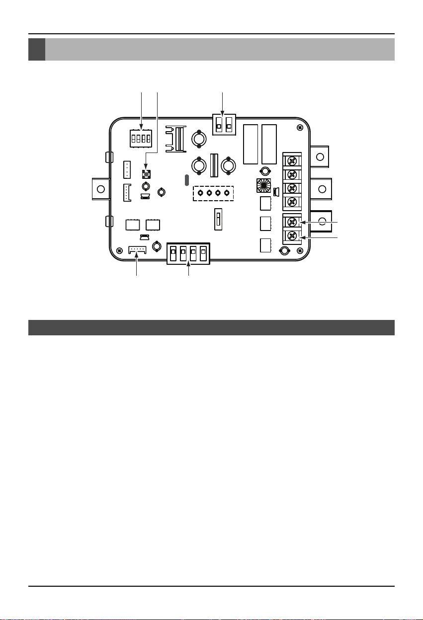
Name of each part
1. CN_PWR : Power input terminal(DC 12V)
2. CN_AO : Signal output terminal to control a water flow control valve(DC 0~10V)
3. CN_OUT : Outdoor unit connector
4. BUS_A : RS-485 (+) terminal
5. BUS_B : RS-485 (-) terminal
6. SWDIP : Switch to select main function
7. SW1 : Reset switch
Variable Water Flow Control Kit
3 2
16 7
4
5
 Loading...