


ENGLISH
FRANÇAIS
ITALIANO
OWNER’S & INSTALLATION
MANUAL
AIR CONDITIONER
Please read this installation manual completely before installing the product.
Installation work must be performed in accordance with the national wiring standards by authorized personnel only.
Please retain this installation manual for future reference after reading it thoroughly..
WIRED REMOTE CONTROLLER
PREMTB100, PREMTBB10, CREMTB100
MFL69312302
Rev.13_061620
DEUTSCH
ESPAÑOL
РУССКИЙ ЯЗЫК
POLSKI
PORTUGUÊS
中文
ČEŠTINA
www.lg.com
Copyright © 2016 - 2020 LG Electronics Inc. All Rights Reserved.
TIPS FOR SAVING ENERGY
2
TIPS FOR SAVING ENERGY
Here are some tips that will help you minimize the power consumption when you use the air
conditioner. You can use your air conditioner more efficiently by referring to the instructions
below:
• Do not cool excessively indoors. This may consume more electricity.
• Block sunlight with blinds or curtains while you are operating the air conditioner.
• Keep doors or windows closed tightly while you are operating the air conditioner.
• Adjust the direction of the air flow vertically or horizontally to circulate indoor air.
• Speed up the fan to cool or warm indoor air quickly, in a short period of time.
• Clean the air filter once every 2 weeks. Dust and impurities collected in the air filter may block the
air flow or reduce the cooling / dehumidifying functions.
For your records
Staple your receipt to this page in case you need it to prove the date of purchase or for warranty
purposes. Write the model number and the serial number here:
Model number :
Serial number :
You can find them on a label on the side of each unit.
Dealer’s name :
Date of purchase :
IMPORTANT SAFETY INSTRUCTIONS
READ ALL INSTRUCTIONS BEFORE USING THE APPLIANCE.
Always comply with the following precautions to avoid dangerous situations and ensure peak
performance of your product
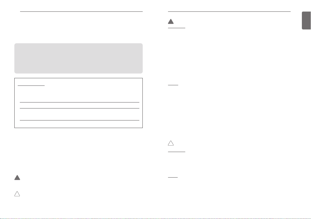
WARNING
!
This symbol indicates potentially hazardous situation which, if not avoided could result in death or
serious injury.
CAUTION
!
This symbol indicates a potentially hazardous situation which, if not avoided, may result in minor
or moderate injury.
IMPORTANT SAFETY INSTRUCTIONS
WARNING
!
Installation
• For electrical work, contact the dealer, seller, a qualified electrician, or an authorized service Center.
- Do not disassemble or repair the product. There is risk of fire, electric shock, explosion, equipment
malfunction, or injury.
• Request to the service center or installation specialty store when reinstalling the installed product.
- There is risk of fire, electric shock, explosion, equipment malfunction, or injury.
• Do not disassemble, fix, and modify products randomly.
- There is risk of fire, electric shock, explosion, equipment malfunction, or injury.
• The product shall be installed according to the national standards and local code.
• Apply totally enclosed noncombustible conduit in case of local building code requiring plenum.
• Use appropriate unit mounting procedures.
• Avoid direct sunlight.
• Avoid moist areas.
3
In-Use
• Do not place flammable objects close to the product.
- There is risk of fire, electric shock, explosion, equipment malfunction or injury.
• Do not allow product to get wet.
- There is risk of fire, electric shock, explosion, equipment malfunction or injury.
• Avoid dropping the product.
- There is risk of fire, electric shock, explosion, equipment malfunction or injury.
• If product gets wet, contact your dealer or authorized service center.
- There is risk of fire, electric shock, explosion, equipment malfunction, or injury. If the instructions are
not followed, it may cause death or severe injury of the user.
• Do not use sharp or pointed objects on product.
- There is risk of fire, electric shock, explosion, equipment malfunction or injury.
• Do not touch or pull the lead wire with wet hands.
- There is risk of product breakdown or electric shock.
CAUTION
!
Installation
• If anyone other than a licensed professional installs, repairs, or alters LG Electronics air conditioning
products, the warranty is voided.
- All costs associated with repair are then the full responsibility of the owner.
• Do not install the unit in potentially explosive atmospheres.
In-use
• Do not clean using powerful detergents like solvent but use soft cloths.
- There is risk of fire, electric shock, explosion, equipment malfunction or deformation.
• Do not press the screen using powerful pressure.
- There is risk of product break-down or malfunction.
ENGLISH
4
TABLE OF CONTENTS
2 TIPS FOR SAVING ENERGY
2 IMPORTANT SAFETY
INSTRUCTIONS
7 DESCRIPTION
8 DESCRIPTION OF THE
OPERATION
8 Main screen
8 Menu screen
9 Setting screen
9 Popup screen
10 Monitoring / Sub function screen
11 Interface screen
11 Returning to the screen
12 OPERATION SETTING
12 On / Off
12 Operation mode
13 Cooling Operation
14 Heating Operation
15 Dry Operation
16 Fan Only Operation
17 AI / Auto operation
18 Dual setpoint auto operation
19 Power Heat Operation
19 Power Cool Operation
20 OPERATION SETTING -
VENTILATOR
20 Operation mode
21 TEMPERATURE SETTING
21 Controlling Desired Temperature
22 Check Room Temperature
23 WIND SETTING
23 Fan speed control
23 Fan speed control - ventilation
23 Air flow control
24 HOME LEAVE SETTING
24 Home leave (Unoccupied Mode)
25 HOLD SETTING
25 Hold
26 ADDITIONAL OPERATION –
VENTILATION
26 Additional operation
27 EXTERNAL EQUIPMENT
CONTROL SETTING
27 External equipment control
28 PLASMA PURIFICATION
SETTING
28 Plasma Purification
29 OVERRIDE CONTROL
SETTING
29 Override control
30 MONITORING SCREEN
30 How to enter fine dust status screen
31 Fine dusts status
32 SUB FUNCTION SETTING
32 Sub function entrance and setting method
33 Energy Saving Setting
34 Plasma Purification Setting
35 Fan Auto Setting
36 Humidification setting
37 Electric Heater Setting
38 Robot Cleaning Setting
39 Ventilation kit Setting
40 Comfort Cooling Setting
41 ZONE CONTROL SETTING
41 Zone Control
42 LOCK SETTING
42 How to enter lock setting
42 Lock setting – all, on/off, mode,
temperature range lock
43 TIMER SETTING
43 Timer entrance and setting method
44 Simple timer
45 Sleep timer
46 Turn-off Reservation
47 Turn-on Reservation
48 SCHEDULE SETTING
48 How to enter schedule
49 Daily Schedule
50 Schedules & Edit
51 Schedules & Edit – Add schedule
52 Exception day
53 ENERGY (air conditioner /
DX ventilator)
53 How to enter energy
54 Instantaneous power check
55 Energy consumption
57 Energy saving - Temperature Setback Timer
58 Energy saving - Time Limit Control
59 Energy setting - outdoor unit capacity
setting
60 Energy setting - target instantaneous power
setting
61 Energy setting - target power consumption
62 Energy setting - target operation time
63 Energy setting - Alarm Popup Setting
64 Energy setting – Usage data initialization
65 FUNCTION SETTING
65 How to enter function setting
66 Function Setting
67 Vane angle control setting
68 Elevation grill setting
69 Robot cleaning setting
69 Auto dry setting
70 Filter sign check and initialization
71 Change temperature setting
72 Dead Band
73 Wi-Fi pairing setting
74 Zone Name setting
75 Override Set Time Setting
76 Home Leave Set Temperature Setting
77 Comfort cooling setting
77 ODU Refrigerant Noise Reduction setting
78 Defrost mode setting
79 Smart load control(SLC) setting
80 Low noise mode time setting
81 Advanced fan speed “Auto” setting
82 Delay time (exclusive for ventilation)
83 Midnight air cooling (ventilation interface)
TABLE OF CONTENTSTABLE OF CONTENTS
84 Human detection mode setting
85 Discharge direction
Fan Control(general ventilator)
86 CO
2
86 Economizer setting
87 USER SETTING
87 How to enter user setting
87 User Setting
88 Language setting
89 Setpoint Type Setting
90 Temperature unit setting
91 Screen saver timer setting
91 LCD brightness in idle setting
92 External device setting
92 External device use
93 External device types
94 On condition / Off condition
95 Date setting
96 Time setting
97 Summer time setting
98 Password setting
99 Schedule initialization
100 Theme setting
100 Humidity display
101 System restart
102 Indoor unit display light brightness setting
103 SERVICE SETTING
103 How to enter service setting
103 Service setting
104 Service contact
105 Model information
106 RMC Version Information
107 Error history
108 Open source license
109 INSTALLATION
109 Installation of Remote Controller
111 Group control
113 INSTALLATION METHOD
TO USE EXTERNAL DEVICE
113 Cable connection method to use external
device
114 AIR CONDITIONER AND
VENTILATION INTERFACE
5
ENGLISH
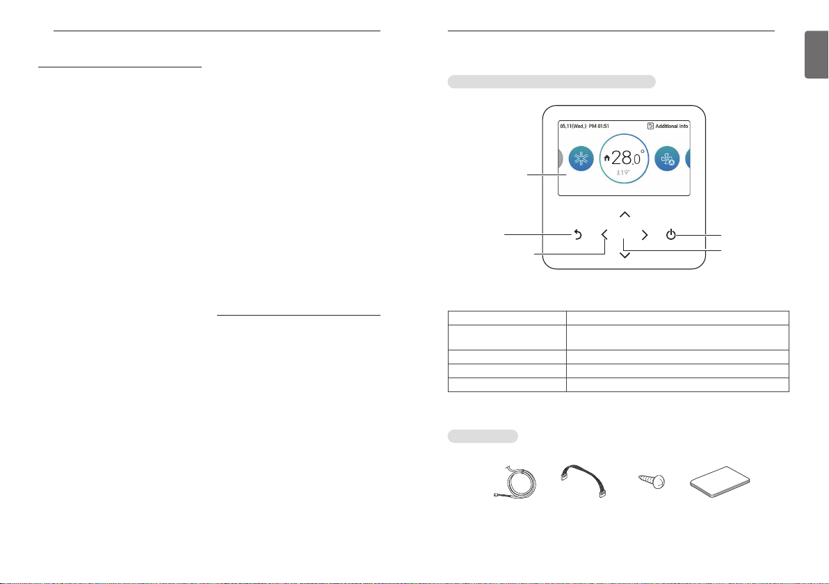
TABLE OF CONTENTS
115 INSTALLER SETTING
115 How to enter installer setting
116 Installer setting – air conditioner
118 Installer setting - ventilator
119 Test run setting (air conditioner / DX
ventilator)
120 Central control address setting (air
conditioner / general, DX ventilator)
121 ESP setting (air conditioner / general, DX
ventilator)
122 Temperature sensor(2TH) setting (air
conditioner / DX ventilator)
123 Ceiling height setting (air conditioner)
124 Static pressure setting(air conditioner)
125 Remote controller master / slave setting (air
conditioner / General, DX ventilator)
126 Override Master/Slave setting (air
conditioner / General, DX ventilator)
127 Dry contact mode setting (air conditioner /
DX ventilator)
128 Fixed air volume (air conditioner / DX
ventilator)
129 Zone Type Setting(air conditioner)
129 Zone Number Setting(air conditioner)
130 Emergency heater setting (air conditioner)
131 Function control during group Control
setting (air conditioner)
132 External devices of indoor unit setting (air
conditioner)
133 Expand of Temperature Range (air
conditioner)
134 Indoor unit address verification (air
conditioner / DX ventilator)
135 Static pressure step setting (air conditioner)
136 Guard timer(air conditioner)
137 Fan speed in Cooling thermal off (air
conditioner)
138 Primary heater setting(air conditioner)
139 Air conditioner Fan operation interlocked
with ventilation setting (air conditioner)
140 Indoor unit Auto-Start setting (air
conditioner / DX ventilator)
141 Occupancy duration time setting(air
conditioner)
142 CN_CC setting (air conditioner)
143 CN_EXT setting (air conditioner / DX
ventilator)
144 Outdoor unit function master setting (air
conditioner / DX ventilator)
145 Fan continuous operation setting (air
conditioner)
146 Low Noise Mode Priority setting (air
conditioner / DX ventilator)
147 Human detection sensor (air conditioner)
148 Humidity sensing position (air conditioner)
149 ODU cycle priority (air conditioner)
151 Outdoor temp. for heating stages (air
conditioner)
152 Estimated energy display (air conditioner)
153 Password initialization (air conditioner /
general, DX ventilator)
154 Auto ESP (air conditioner)
Dust step color setting
156
156 Product direction (general ventilator)
157 Express ventilation priority (general , DX
ventilator)
158 Humidification of stand-alone ventilation
mode (general , DX ventilator)
159 Humidification of ventilation with heating
operation (DX ventilator)
160 Ventilation Fan Speed Alignment (general
ventilator)
160 Filter check alarm(general ventilator)
161 GUIDE TO DIFFERENT
MODE OPERATION/OPEN
SOURCE SOFTWARE
161 Different mode operation
161 Open Source Software Notice Information
DESCRIPTION
NEW STANDARD REMOTE CONTROLLER
Operation display
window
Back button
Up/Down/Left/Right
Button
Operation display window
Back button
Up/down/left/right button
OK button
On/Off button
Operation and Settings status display
When you move to the previous stage from the menu’s setting stage
When you change the menu’s setting value
When you save the menu’s setting value
When you turn ON/OFF the air conditioner
Accessories
Connecting Cable DO Port Remote controller
OK
fixing screws
(4 EA)
DESCRIPTION
On/Off Button
OK Button
Quick Guide
76
ENGLISH
DESCRIPTION OF THE OPERATION
8
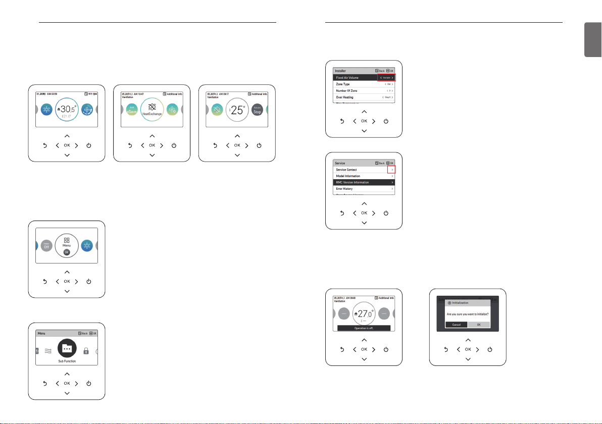
DESCRIPTION OF THE OPERATION
Main screen
In the main screen, press [<, >(left/right)] button to select the category to set, and you can control by pressing [∧,∨ (up/down)] button.
< Air conditioner main screen> <General Ventilation main
screen>
Menu screen
In the main screen, press [<, >(left/right)] button to select the menu and press [OK] button to
move to menu screen.
In the menu screen, press [<, >(left/right)] button to select the category to set, and press [OK]
button to move to the detail screen.
<Dx Ventilation main screen>
DESCRIPTION OF THE OPERATION
Setting screen
Select the category to set using [∧,∨(up/down)] button.
In each detail screen of the menu, as in the box in the left figure,
when “<,>” icons are displayed at the same time, you can immediately apply the setting value by pressing [<, >(left/right)]
button.
※ For the values that can be set in each category, refer to the
detail manual for each function.
In each detail screen of the menu, as in the box in the left figure,
if only “>” icon is displayed, you can move to the detail setting
screen by pressing [>(right) or OK] button.
※ For the values that can be set in each category, refer to the
detail manual for each function.
Popup screen
The toast message is the message displayed at the bottom of the screen when an operation is
turned On/Off or if a function is set / cancelled.
The popup message is mainly displayed when an error occurred in the product.
9
ENGLISH
< Toast message > < Popup message >
DESCRIPTION OF THE OPERATION
10
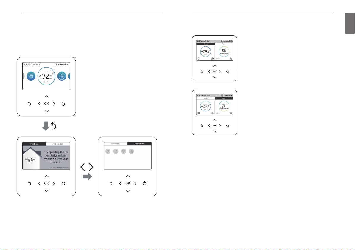
Monitoring / Sub function screen
In the main screen, you can enter the monitoring / sub function screen by pressing [Back] button
and then pressing [<, >(left/right)] button.
- In the monitoring screen, you can check the indoor temperature and outdoor unit monitoring information.
- In the sub function screen, you can turn on or off the sub function supported by the product.
DESCRIPTION OF THE OPERATION
Interface screen
Select the product (air conditioner or ventilation) to set using [<, >(left/right)] button.
When you control the air conditioner and the ventilation product
with one remote controller, the screen is displayed as in the side
figure. You can set the air conditioner by pressing [<(left)] button and pressing [OK] button to move to the air conditioner
screen.
When you control the air conditioner and the ventilation product
with one remote controller, the screen is displayed as in the side
figure. You can set the ventilation by pressing [>(right)] button
and pressing [OK] button to move to the ventilation screen.
Returning to the screen
In the main screen, after moving to the category by pressing [<, >(left/right)] button, if there is no
remote controller operation, after 10 seconds, it returns to the main screen basic position. (basic
position: indoor temperature display part)
In the screens except the main screen, if there is no remote controller operation for 1 minute, it
moves to the main screen.
11
ENGLISH
OPERATION SETTING
12
OPERATION SETTING
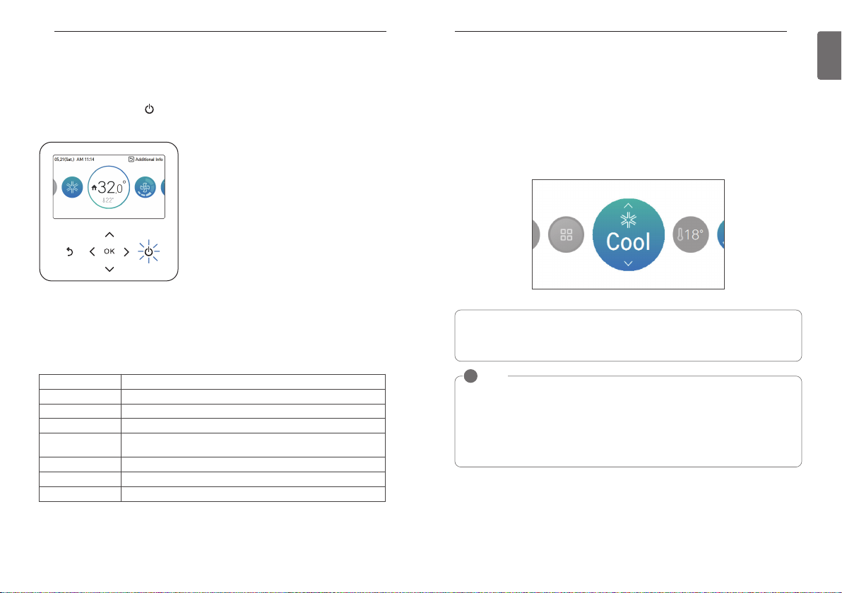
On / Off
Air conditioner and ventilator will be turned on or off.
Press the remote controller’s (On/Off) button.
- If the product is in operation, On/Off button will be illuminated.
If the product is in off, On/Off button backlight will be off.
OPERATION SETTING
Cooling Operation
Cooling operation’s minimum setting temperature is 18°C (16°C).
For some types of the indoor units, the desired temperature can be controlled in the units of 1°C
or 0.5°C.
- Set the desired temperature lower than the indoor temperature.
- Indoor temperature is displayed on the default screen of the remote controller.
- If the setpoint is set higher than the room temperature, then the unit will remain in the cool
mode but will not begin to cool unit the room temperature exceeds the setpoint.
- If you unit is operating in cooling mode and you press the [On/Off] button the cooling operation
will shut off.
13
ENGLISH
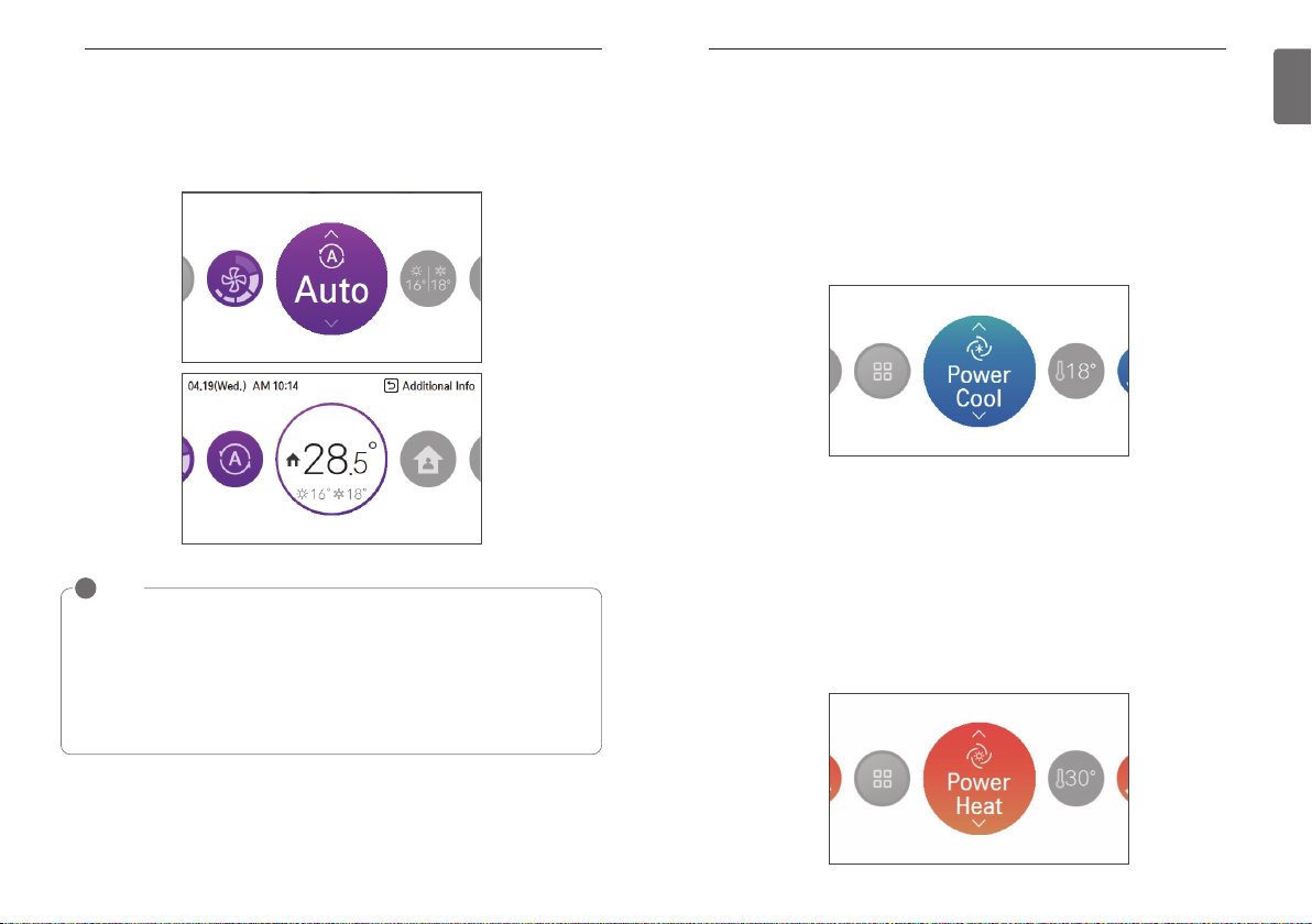
Operation mode
You can easily control the desired operation mode.
In the main screen, press [<,>(left/right)] button to select the operation mode or home leave or
hold category, and press [∧,∨(up/down)] button to set the operation mode.
※Some products may not support some operation modes.
Mode Description
Cool Cool the room to the desired temperature.
Dry It removes the moisture with cooling.
Heat Heats the room to the desired room temperature.
AI / Auto
Fan Fan only operation, no cooling or heating.
Power Cool It provides strong cooling in short time.
Power heating Power heating increases indoor temperature quickly.
The product automatically provides the appropriate fan speed based on
the temperature of the room.
What is 3 minute delay function?
After the cooling stops, when the product is started right away, the reason that the cold
wind does not come out is that it is the function to protect the compressor.
The compressor starts after 3 minutes and the cold wind comes out.
NOTE
!
The compressor starts after 3 minutes and the cold wind comes out.
In the cooling operation, you can select the desired temperature in the range of 18°C ~ 30°C
(16°C ~ 30°C).
The favorable temperature difference between the indoor temperature and the outdoor
temperature is 5°C.
For some types of the indoor units, you can select the desired temperature in the range of
16°C ~ 30°C.
OPERATION SETTING
14
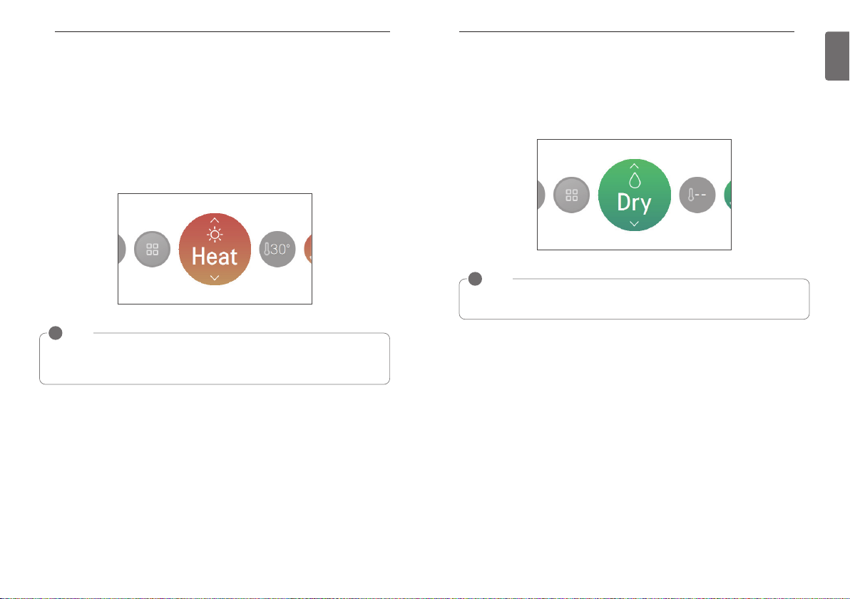
Heating Operation
The heating operation’s minimum setting temperature is 16°C.
For some types of the indoor units, the desired temperature can be controlled in the units of 1°C
or 0.5°C.
- Set the desired temperature higher than the indoor temperature.
- Indoor temperature is displayed on the default screen of the remote controller.
- When the desired temperature is set lower than the indoor temperature, warm air doesn't
come out, but for some products, the fan will recirculate room air, or stop altogether.
- If you unit is operating in heating mode and you press the [On/Off] button the heating operation
will shut off.
NOTE
!
In the heating operation, you can select the desired temperature in the range of 16°C ~ 30°C.
Heating operation is operated only in cooling/heating model. The heating is not operated in
cooling exclusive model.
OPERATION SETTING
Dry Operation
Dry operation’s initial fan speed is “Low”.
Dry operation does not have a separate desired temperature.
- If you unit is operating in dehumidification mode and you press the [On/Off] button the dehumidification operation will shut off.
NOTE
!
If you use it in the rainy season, or when the humidity is high, you can have both the
effective dehumidification and cooling operation at the same time.
15
ENGLISH
OPERATION SETTING
16
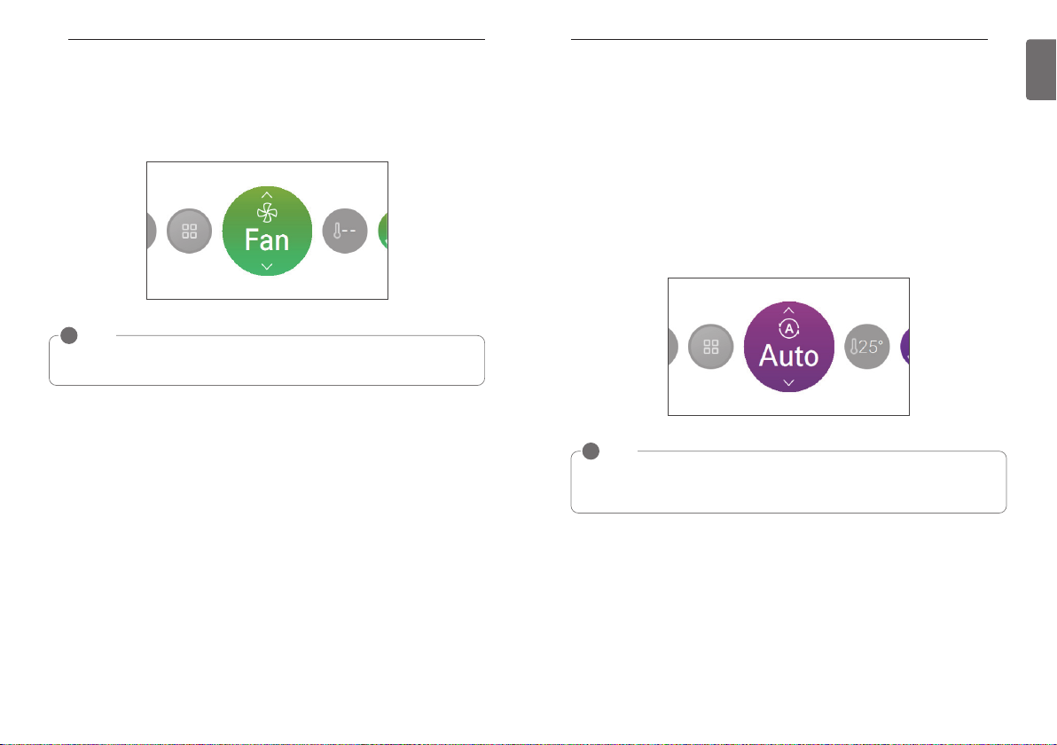
Fan Only Operation
Fan only operation’s initial wind strength is “High”.
Fan only operation does not have a separate desired temperature.
- If you unit is operating in fan only mode and you press the [On/Off] button the the unit will stop.
NOTE
!
It provides the Fan only operation without temperature control, with recirculation of indoor
air.
OPERATION SETTING
AI / Auto operation
Auto operation’s initial desired temperature is 25°C.
The cooling exclusive model’s initial desired temperature is “It’s Fine”.
Cooling/heating model’s desired temperature can be controlled in the units of 1°C or 0.5°C.
For cooling exclusive model, the value can be controlled from “hot” stage to “cold” stage.
- Hot
- A little hot
- It’s fine
- A little cold
- Cold
- If you unit is operating in ai/auto mode and you press the [On/Off] button the ai/auto operation
will shut off.
NOTE
!
If the product is a cooling/heating model, in the auto operation, the desired temperature can
be selected in the range of 18°C ~ 30°C.
If it does not operate as you wish, select another operation mode.
17
ENGLISH
OPERATION SETTING
18
Dual setpoint auto operation
The indoor unit automatically manages room temperature with extended heating and cooling setting temperature ranges.
Dual setpoint auto mode can be set in the USER SETTING. This is recommended in North America region.
NOTE
!
• Auto heating function only operates on cooling and heating models.
• Auto heating function doesn’t operate on cooling only models.
• When remote controller has a connection with indoor unit that does not support 'dual
setpoint', thermal operation function of indoor unit is replaced with ON/Off control from the
wired remote, when the user sets target temperatures in the below ranges.
- cooling target temp. range : 87~99 °F (30.5~37.5 °C)
- heating target temp. range : 40~59 °F (4~15.5 °C).
OPERATION SETTING
Power Cool Operation
Power cooling quickly lowers the indoor temperature.
Desired temperature: 18°C
Fan speed : Power fan speed
Fan direction: Current fan direction
- During the power cooling, if fan speed or desired temperature is changed, the power cooling is
cleared, and it operates in the cooling operation mode.
- During the power cooling, if you press [On/Off] button, the power cooling operation stops, and
when you press [On/Off] button again, it operates in the cooling operation mode.
Power Heat Operation
Power heating increases indoor temperature quickly.
Desired temperature: 30 °C
Fan speed: Power fan speed
Fan direction: Current fan direction
- If you adjust the fan speed or the desired temperature during power heating, the function is disabled and heating operation mode is activated.
- If you press [On/Off] button during power heating, the function stops and if you press [On/Off]
button again, heating operation mode is activated.
19
ENGLISH
OPERATION SETTING - VENTILATOR
20
TEMPERATURE SETTING
21
ENGLISH
OPERATION SETTING - VENTILATOR
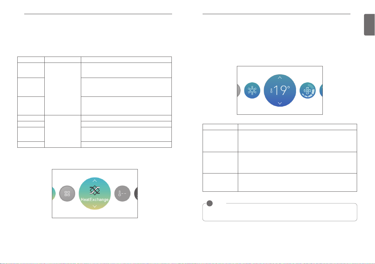
Operation mode
Ventilation (general and direct cooling type ventilation) operation mode supports the following operation modes.
※Some products may not support some operation modes.
Mode Classification Description
Auto
Ventilation operation
Heat Exchange
Bypass
In the main screen, press [<,>(left/right)] button to select the operation mode category, and press
[∧,∨(up/down)] button to set the operation mode.
mode – commonly
supported by ventilation products
Cool
Heat It provides warm air to the room.
Air conditioner operation mode – supports
direct cooling type
Auto
ventilation
Stop It stops the product’s air conditioner operation.
It measures the ventilation system’s indoor temperature and the outdoor temperature for the automatic operation in the optimal ventilation mode state.
It is the mode of ventilation with both supply/discharge
through the heat exchanger. It is adequate to use in
summer/winter where the indoor/outdoor temperature
difference is big.
It is the ventilation where the exhausted air is ventilated
without going through the exchanger. It is adequate to
use in spring/fall or when the indoor contamination is
severe.
Cools down the room to desired temperature.
The product automatically provides the appropriate fan
speed based on the temperature of the room.
TEMPERATURE SETTING
Controlling Desired Temperature
You can easily control to the desired temperature.
• In the main screen, press [<,>(left/right)] button to select the desired temperature category,
and press [∧,∨(up/down)] button to set the desired temperature.
- In the cooling, heating, and AI/auto mode, the desired temperature control is possible.
Mode Description
If the desired temperature is higher than the indoor temperature, the
Cool
Heat
AI / Auto
NOTE
!
The favorable temperature difference between the indoor temperature and the outdoor
temperature is 5°C.
cooling is not performed.
Set the desired temperature lower than the indoor temperature.
You can select in the range of 18°C ~ 30°C (16°C ~ 30°C).
If the desired temperature is lower than the indoor temperature, the heating is not performed.
Set the desired temperature higher than the indoor temperature.
You can select in the range of 16°C ~ 30°C.
For cooling/heating product, you can select in the range of 18°C ~ 30°C.
For cooling exclusive product, you can select Hot, A little hot, Adequate,
A little Cold, and Cold.
※The direct cooling type ventilation’s air conditioner operation mode is composed separately
from the ventilation operation mode.
TEMPERATURE SETTING
22
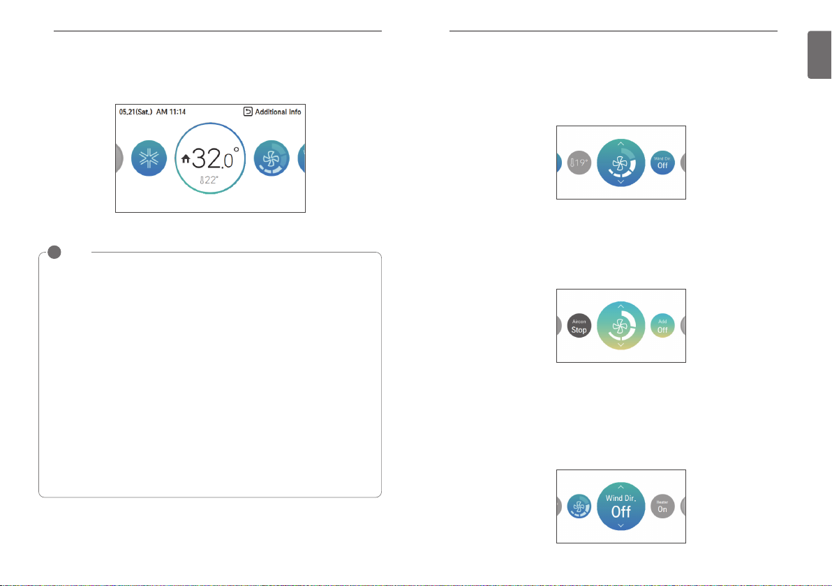
Check Room Temperature
You can check the current indoor temperature.
• In the remote controller’s the main screen, you can check the indoor temperature.
NOTE
!
The temperature distribution in the remote controller installation space is not uniform, so
there can be a little difference between the temperature you actually feel and the remote
controller’s room temperature display
According to Control type setting value
• Single setpoint
Fahrenheit: 52~99 °F
- below 52 °F: display ‘LO’
- over 99 °F: display ‘HI’
Celsius: 10.5~39.5 °C
- below 10.5 °C: display ‘LO’
- over 39.5 °C: display ‘HI’
• Dual setpoints
Fahrenheit: 34~99 °F
- below 34 °F: display ‘LO’
- over 99 °F: display ‘HI’
Celsius: 0.5~39.5 °C
- below 0.5 °C: display ‘LO’
- over 39.5 °C: display ‘HI’
- For indoor temperature below 50 °F (10 °C), the value perceived by the Thermostat(with
cable) is displayed.
• Because of location of Temperature sensing, the real room temperature and the this
displayed value can be different.
WIND SETTING
WIND SETTING
Fan speed control
From the main screen, press [<,>(left/right)] button to select the fan speed category, and press
[∧,∨(up/down)] button to set the fan speed control the desired fan speed.
- It circulates in the order of Slow ↔ Low ↔ Medium ↔ High ↔ Power ↔ Auto.
※For some product some fan speed may not be available.
Fan speed control - ventilation
You can easily control the desired fan speed.
• In the main screen, press [<,>(left/right)] button to select the fan speed category, and press
[∧,∨(up/down)] button to set the fan speed.
- It circulates in the order of low ↔ high ↔ power ↔ auto.
※The auto Fan can be used only when the air contamination (CO
Air flow control
You can easily control the desired air flow
• In the main screen, press [<,>(left/right)] button to select the air flow category, and press
[∧,∨(up/down)] button to set the air flow.
- It circulates in the order of Off ↔ Up/Down swing ↔ Left/Right swing ↔ Up/Down/Left/Right
swing ↔ Swirl ↔ Indirect wind ↔ Direct wind ↔ Human detection direct wind ↔ Human detection indirect wind ↔ Smart mode ↔ Refresh mode.
2
) sensor is installed.
23
ENGLISH
※For some product some air flow settings may not be available.
HOME LEAVE SETTING
24
HOLD SETTING
25
ENGLISH
HOME LEAVE SETTING
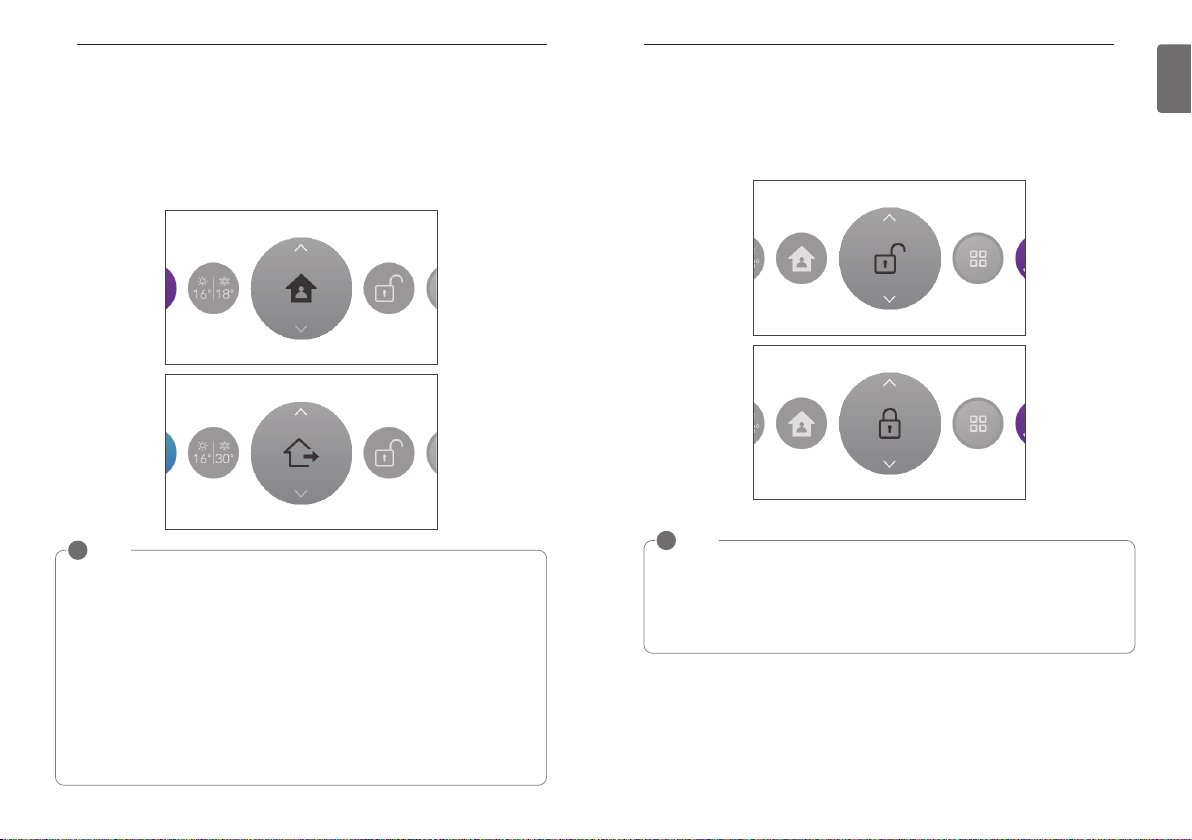
Home leave (Unoccupied Mode)
The "Home Leave" function enables proper operation of indoor unit when a space is left for a period of time.
This feature can only be used when Control type setting is set to the Dual Set Point Control
mode
NOTE
!
User can not change indoor unit status with wired remote controller while set 'home leave
mode' except for 'home leave mode' release control.
• Home leave mode will be released if indoor unit operation was changed by commands of
other controllers(central controller, drycontact and wireless remote controller).
• When occupied schedule event occurs while operate a home leave mode, home leave
mode will be released and indoor unit status follow the occupied schedule event.
• Indoor unit operation change as below when the home leave mode is released.
- The setpoints and operation mode values are reflected in the control events of the
scheduled events that are currently applied.
- If there are no schedule events, the setpoint shall be applied as last setpoints before the
home leave operation.
- If there are no setpoints before the 'home leave' operation(dehumidification or fan mode),
default values will be applied to the setpoints.
- Default values : dual setpoint auto , heat 60 °F(16 °C), cool 86 °F(30 °C)
HOLD SETTING
Hold
User can use this function when they want to manage indoor unit as home leave control mode
only.
NOTE
!
Can not change indoor unit status with wired remote controller while set ‘hold mode' except
for ‘hold mode' release control.
• Hold mode will be released if indoor unit operation was changed by commands of other
controllers(central controller, drycontact and wireless remote controller).
• A scheduled event is not applied to the indoor unit during a hold mode, even if a scheduled
event is set.
ADDITIONAL OPERATION –VENTILATION
26
EXTERNAL EQUIPMENT CONTROL SETTING
27
ENGLISH
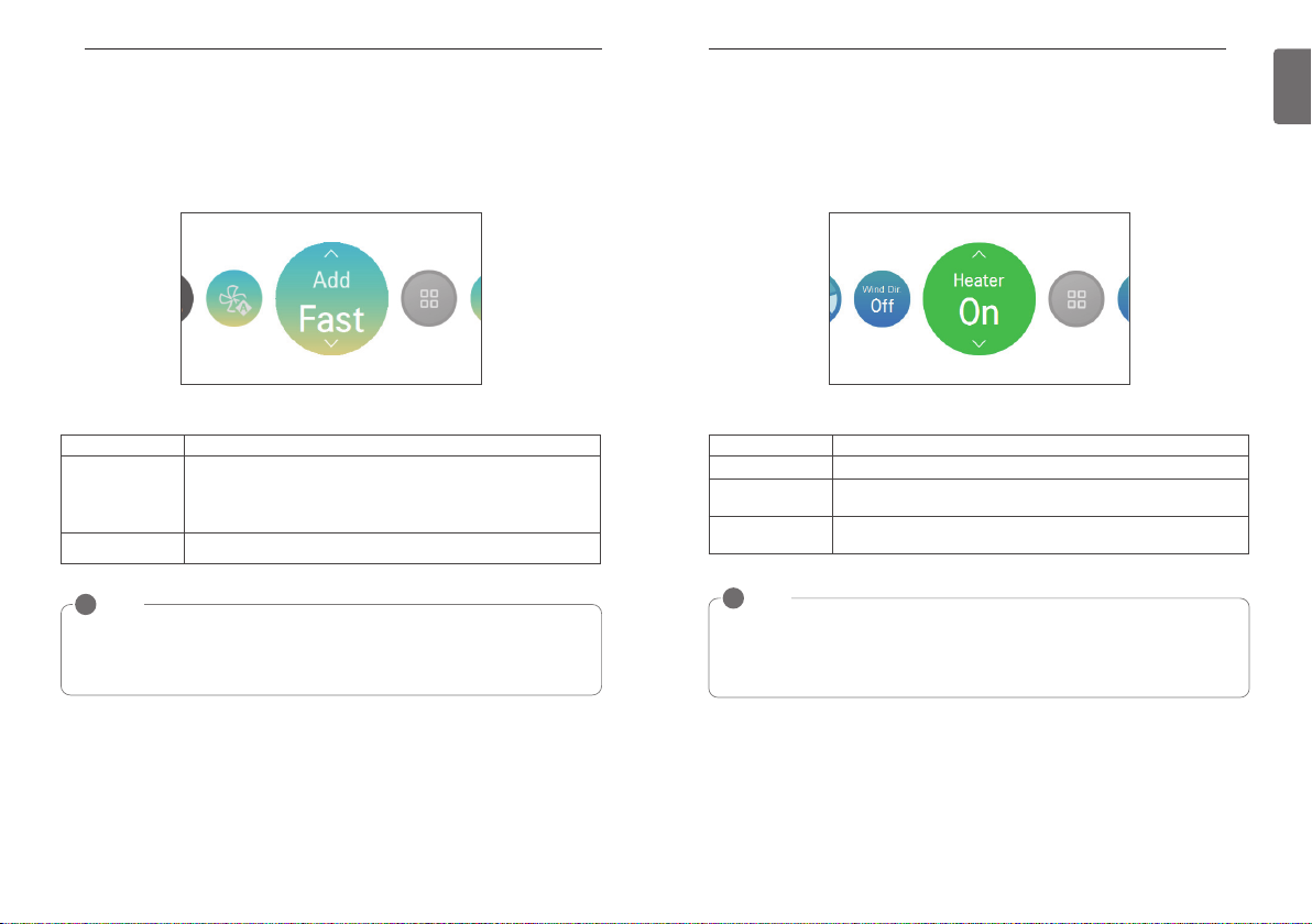
ADDITIONAL OPERATION –VENTILATION
Additional operation
You can change the additional operation of the ventilation product.
• In the main screen, press [<,>(left/right)] button to select the additional operation category, and
press [∧,∨(up/down)] button to set the additional operation.
Additional Operation Description
It ventilates in short period of time.
Fast
Energy saving It performs the energy saving function while ventilating efficiently.
NOTE
!
The general ventilation and the direct cooling type ventilation’s additional operation are the
same.
The ventilation product’s additional functions (air cleaning / heater / humidification / fan auto)
setting methods are the same as the air conditioner.
It is the function to operate the ventilation function more efficiently
through the express setting which is an additional operation of the ventilation product.
EXTERNAL EQUIPMENT CONTROL SETTING
External equipment control
It is the function to set the contact point output of the external equipment control mode.
• In the main screen, press [<,>(left/right)] button to select the external equipment control category, and press [∧,∨(up/down)] button to set the contact point output.
Mode Description
On When it is set to “On”, it always performs the contact point output.
Off
Auto
NOTE
!
Please use the corresponding function when the external equipment is actually connected.
When the external equipment is not set, please maintain “Off” status.
For the detail external equipment control condition setting, refer to the user setting - external
equipment logic setting.
When you set it to “Off”, it does not perform the contact point output in
any case.
When it is set to “auto”, the contact point output is decided according to
the user setting’s external equipment logic setting value.
PLASMA PURIFICATION SETTING
28
OVERRIDE CONTROL SETTING
29
ENGLISH
PLASMA PURIFICATION SETTING
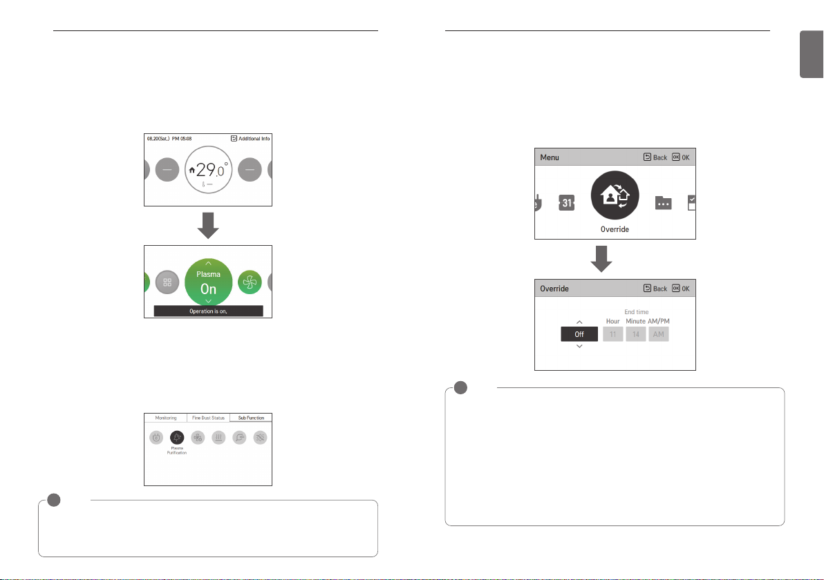
Plasma Purification
It cleans and makes pleasant indoor air.
1. Plasma Purification - single operation
If plasma purification is turned on in operation Off state, plasma purification single operation is
performed.
In case of plasma purification single operation, it operates in fan mode / automatic wind state,
and the wind direction operated before the plasma purification single operation is turned off.
There are 3 ways to end the plasma purification single operation.
1) Input of On/Off button during plasma purification single operation
2) Select plasma purification OFF
3) Change operation mode during plasma purification single operation
2. Plasma purification - additional operation
NOTE
!
• If mode is changed during plasma purification single operation, it is switched to the air
cleaning additional operation.
• Air cleaning operation may not be displayed or performed in some products.
OVERRIDE CONTROL SETTING
Override control
In dual setpoint setting, wired remote controller can manages indoor unit status based on programmed control events which have occupancy option.
Override control function switches between ‘occupied’ and ‘unoccupied’, and vice-versa.
User can set timer option which can return to original schedule event in override function menu.
OK
NOTE
!
• If there are no 'occupied' schedule event when operate 'override' control, wired remote
controller change indoor unit operation as below default setting value.
- operation mode : Auto
- target temperature : 86 °F(30 °C)(cool), 60 °F(16 °C)(heat)
• If there are no ‘unoccupied' schedule event when operate 'override' control, wired remote
controller change indoor unit operation as 'home leave' mode default value.
- operation mode : Auto
- target temperature: 'home leave' target temperature.
• If wired remote controller received command from other controller, ‘Override’ operation will
be released.
• When schedule event occurs while operating an override mode, override mode will be released and indoor unit status follow the schedule event.
MONITORING SCREEN
30
MONITORING SCREEN
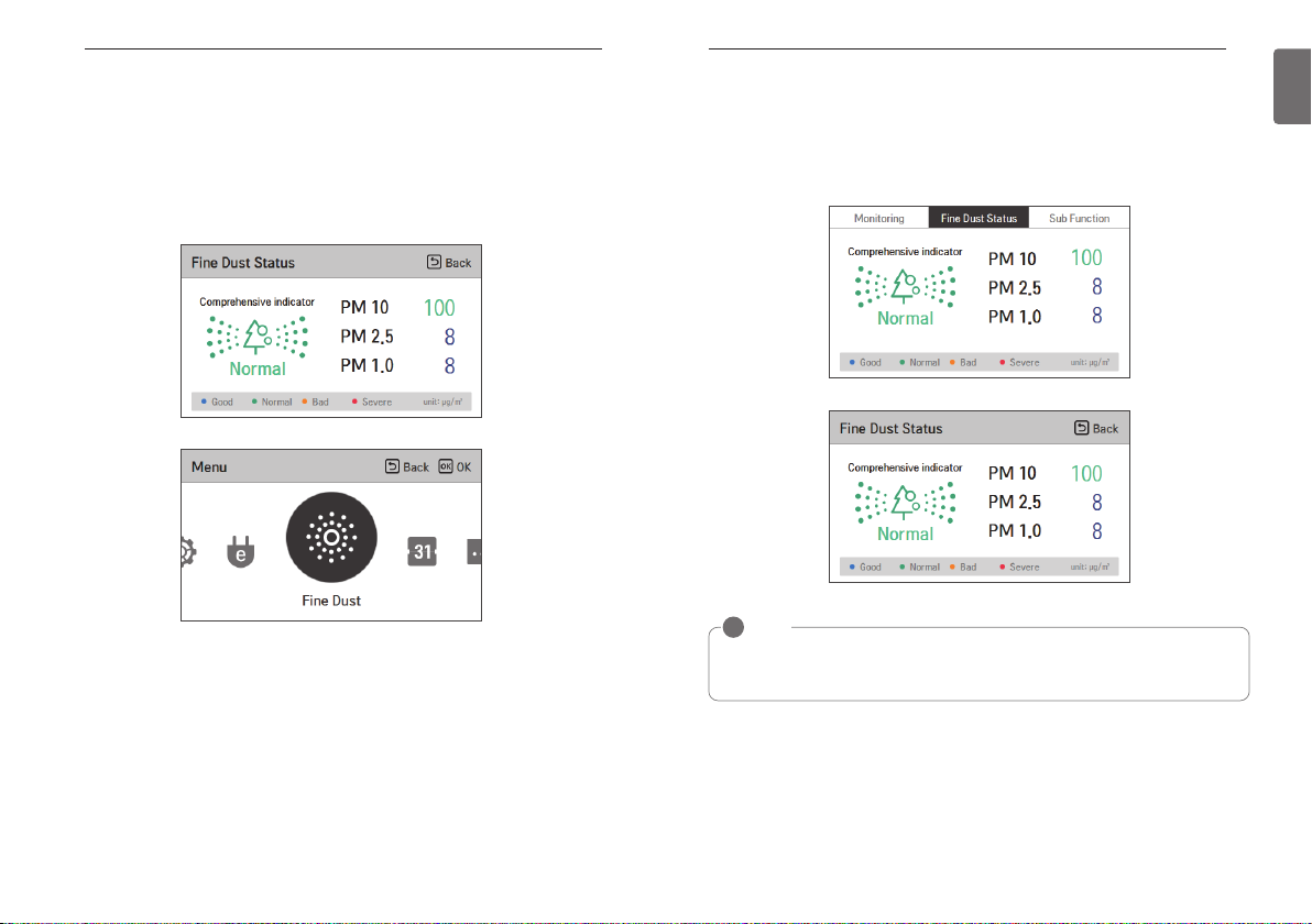
How to enter fine dust status screen
• In the main screen, press [Back] button to move to monitoring/additional functions screen, and
press [<, > (left/right)] button to move to fine dust status screen. (Method 1)
• In the menu screen, press [<, > (left/right)] button to select the fine dust screen category, and
press [OK] button to move to the fine dust status screen. (Method 2)
MONITORING SCREEN
Fine dusts status
It is the function to monitor dust value measured by the dust sensor mounted inside the air conditioner.
• In the fine dust status screen, you can check fine dust, ultra fine dust, and super ultra fine dust
concentration values.
• The overall index displays the worst dust status value among the three dust status values.
NOTE
!
• The fine dust status may not be displayed in some products.
• Fine dust status can be checked only when the product is in operation.
31
ENGLISH
SUB FUNCTION SETTING
32
SUB FUNCTION SETTING
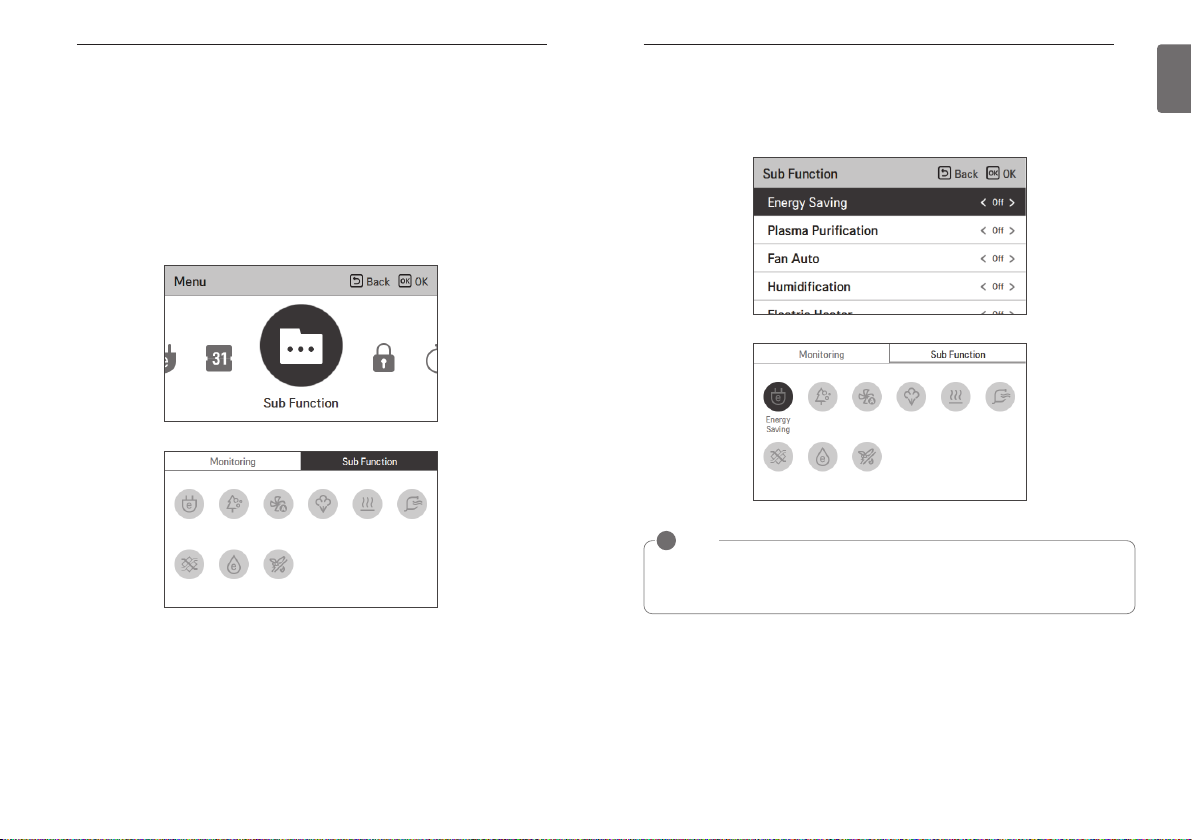
Sub function entrance and setting method
In the menu screen, press [<,>(left/right)] button to select the sub function category, and press
[OK] button to move to the sub function setting list screen.
In the sub function setting list screen, if you press [<, >(left/right)] button, you can turn on/off the
corresponding sub function. (method 1)
In the main screen, press [Back] button to move to the monitoring/sub function screen, and press
[<,>(left/right)] button to move to the sub function screen. In the sub function screen, select the
sub function category to set, and if you press [OK] button, you can turn on/off the corresponding
function. (method 2)
SUB FUNCTION SETTING
Energy Saving Setting
The energy saving cooling function is the function to control the desired temperature during the
cooling operation to improve the comfort of the user and to improve the power saving performance.
NOTE
!
The energy saving function is an additional function, and it may not be displayed/operated in
some products.
The energy saving function is possible only when the product is in the cooling operation.
33
ENGLISH
SUB FUNCTION SETTING
34
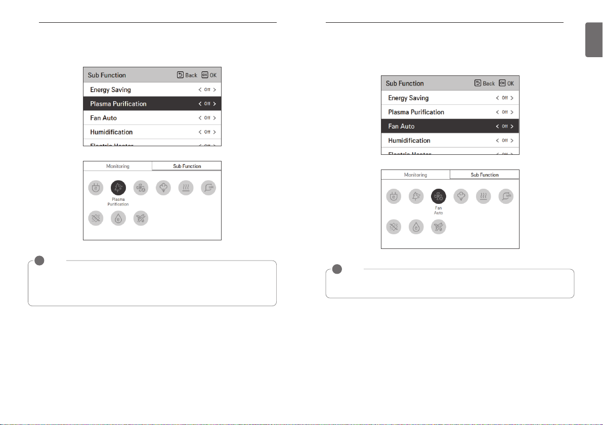
Plasma Purification Setting
It makes the indoor air clean and pleasant.
NOTE
!
The air cleaning function is an additional function, and it may not be displayed/operated in
some products.
The air cleaning function is possible only when the product is in operation.
If you want air cleaning single operation, set air cleaning in the wind only operation.
SUB FUNCTION SETTING
Fan Auto Setting
Select fan operation after performing thermal control of indoor units.
If set to 'ON', fan operation keeps on after thermal operation of indoor units.
NOTE
!
The fan auto function is an additional function, and it may not be displayed/operated in some
products.
35
ENGLISH
SUB FUNCTION SETTING
36
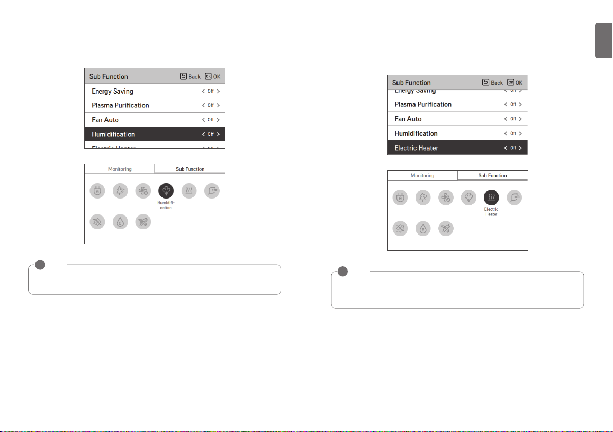
Humidification setting
It is the function to activate the humidifier installed in the product when the indoor air is dry.
NOTE
!
The humidification function is an additional function, and it may not be displayed/operated in
some products.
SUB FUNCTION SETTING
Electric Heater Setting
It is the function to reinforce the heating capability by turning on the electric heater during the
heating operation.
NOTE
!
It can be set only in the heating operation.
The heater function is an additional function, and it may not be displayed/operated in some
products.
37
ENGLISH
SUB FUNCTION SETTING
38
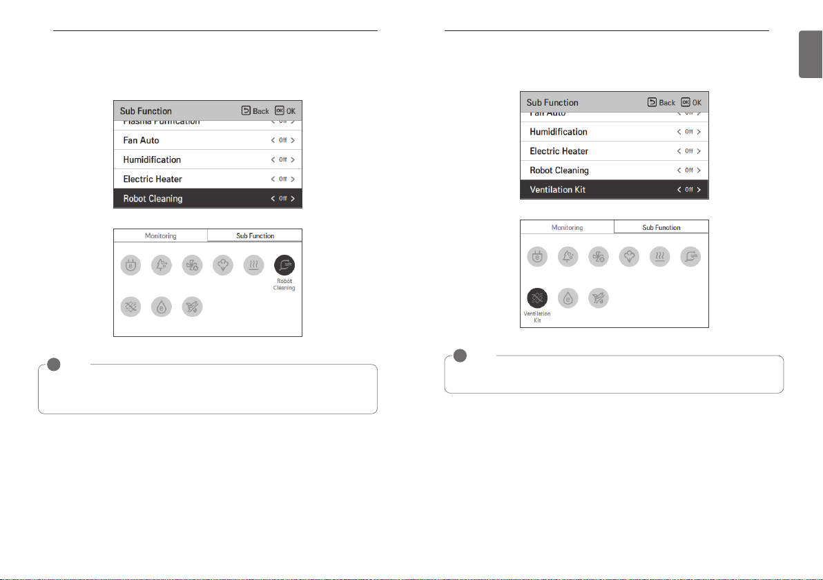
Robot Cleaning Setting
Robot cleaning function is the function to automatically perform the filter cleaning with the
cleaner in the product when the air conditioner is used for certain period of time.
NOTE
!
It can be set 30 seconds after the operation stopped.
The robot cleaning function is an additional function, and it may not be displayed/operated in
some products.
SUB FUNCTION SETTING
Ventilation kit Setting
Function enables operation of an optional ventilation kit with indoor units
NOTE
!
The ventilation kit function is an additional function, and it may not be displayed/operated in
some products.
39
ENGLISH
SUB FUNCTION SETTING
40
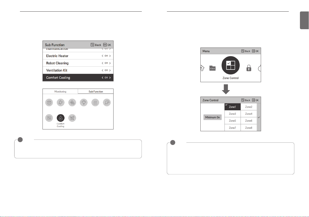
Comfort Cooling Setting
The comfort cooling is the function to automatically control the cooling strength to maintain the
pleasant feeling without turning off the product after the indoor temperature reached the desired
temperature.
NOTE
!
The comfort cooling function is an additional function, and it may not be displayed/operated in
some products.
The comfort cooling function is only possible when the product is in the cooling operation.
ZONE CONTROL SETTING
ZONE CONTROL SETTING
Zone Control
A function to control zone with duct type indoor units.
Wired Remote controller can control maximum 8 zones.
OK
NOTE
!
According to installation setting value
• If no function is supported this entry can not function.
• Old type
- Zone control is currently only available to monitor.
• New type(4zone or 8Zone)
- Any number of zones is installed is displayed on the screen can be controlled.
41
ENGLISH
LOCK SETTING
42
TIMER SETTING
43
ENGLISH
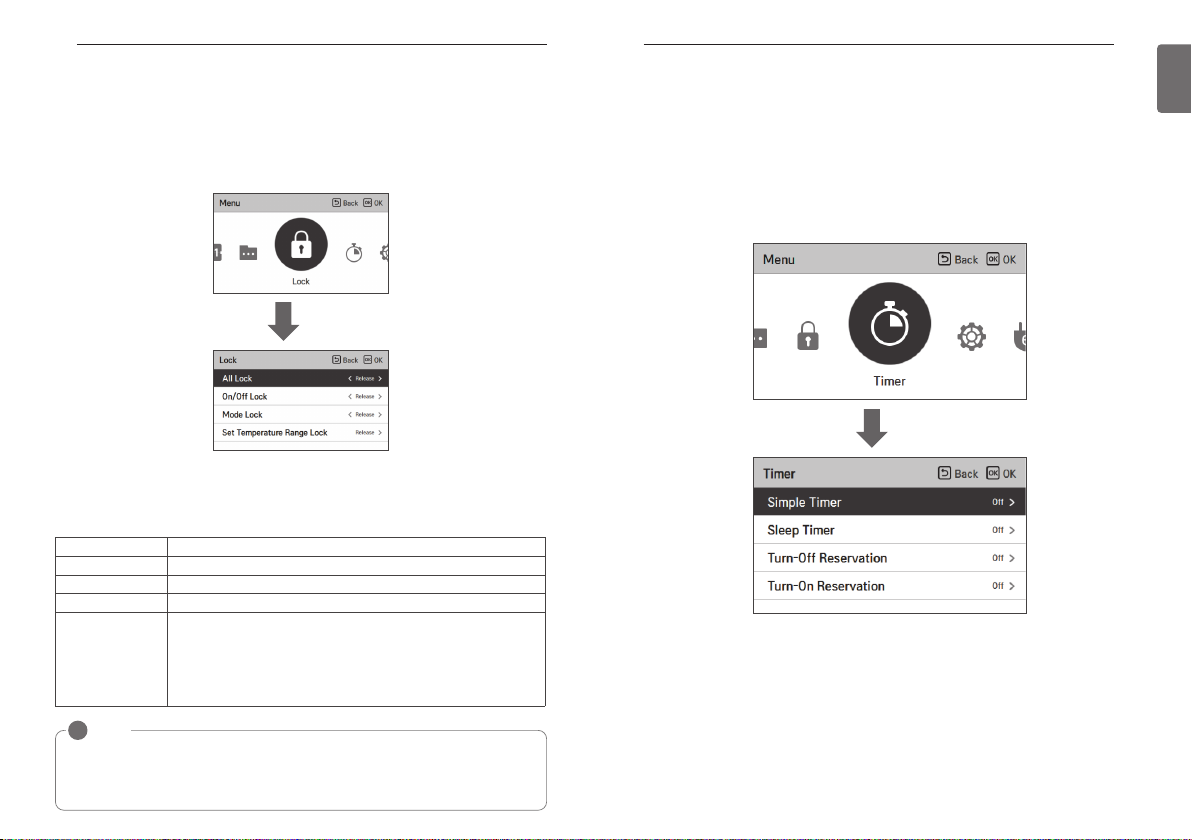
LOCK SETTING
How to enter lock setting
• In the menu screen, press [<,>(left/right)] button to select “lock setting” category, and press
[OK] button to move to the lock setting list screen.
• In the lock setting list, if you press [∧ ,∨(up/down)] button, you can turn on/off the corresponding lock function.
OK
Lock setting – all, on/off, mode, temperature range lock
• It is the function to lock the button operation of the remote controller so that children or other
persons cannot use it without permission.
•
It is the function to limit the desired temperature range that can be set in the wired remote controller.
Lock Description
All lock It locks all button operation of the remote controller.
On/Off lock It locks the On/Off button operation of the remote controller.
Mode lock It locks the operation mode button operation of the remote controller.
It is the function that can limit the range of the desired temperature that
Temperature range
lock
can be set in the wired remote controller.
- Single: Lower limit : 16~30 °C (60~86 °F)
Upper limit : 16/18~30 °C (60/64~86 °F)
- Dual : Cooling : 50~99 °F (10~37.5 °C)
Heating : 40~90 °F (4~32 °C)
TIMER SETTING
Timer entrance and setting method
• In the menu screen, press [<,>(left/right)] button to select the timer category, and press [OK]
button to move to the timer setting list screen.
• In the timer setting list screen, press [∧,∨(up/down)] button to select the timer to set, and
press [OK] button to move to the detail screen.
• After setting the value, when you press [OK] button, the timer is activated.
• After setting the value, if you press [Back] button, the changed value will not be applied.
OK
NOTE
!
In the central controller, when the central control temperature range lock is set, the wired
remote controller’s temperature lock setting is cleared.
The temperature change by external equipment is reflected regardless of the remote
controller temperature range lock.
TIMER SETTING
44
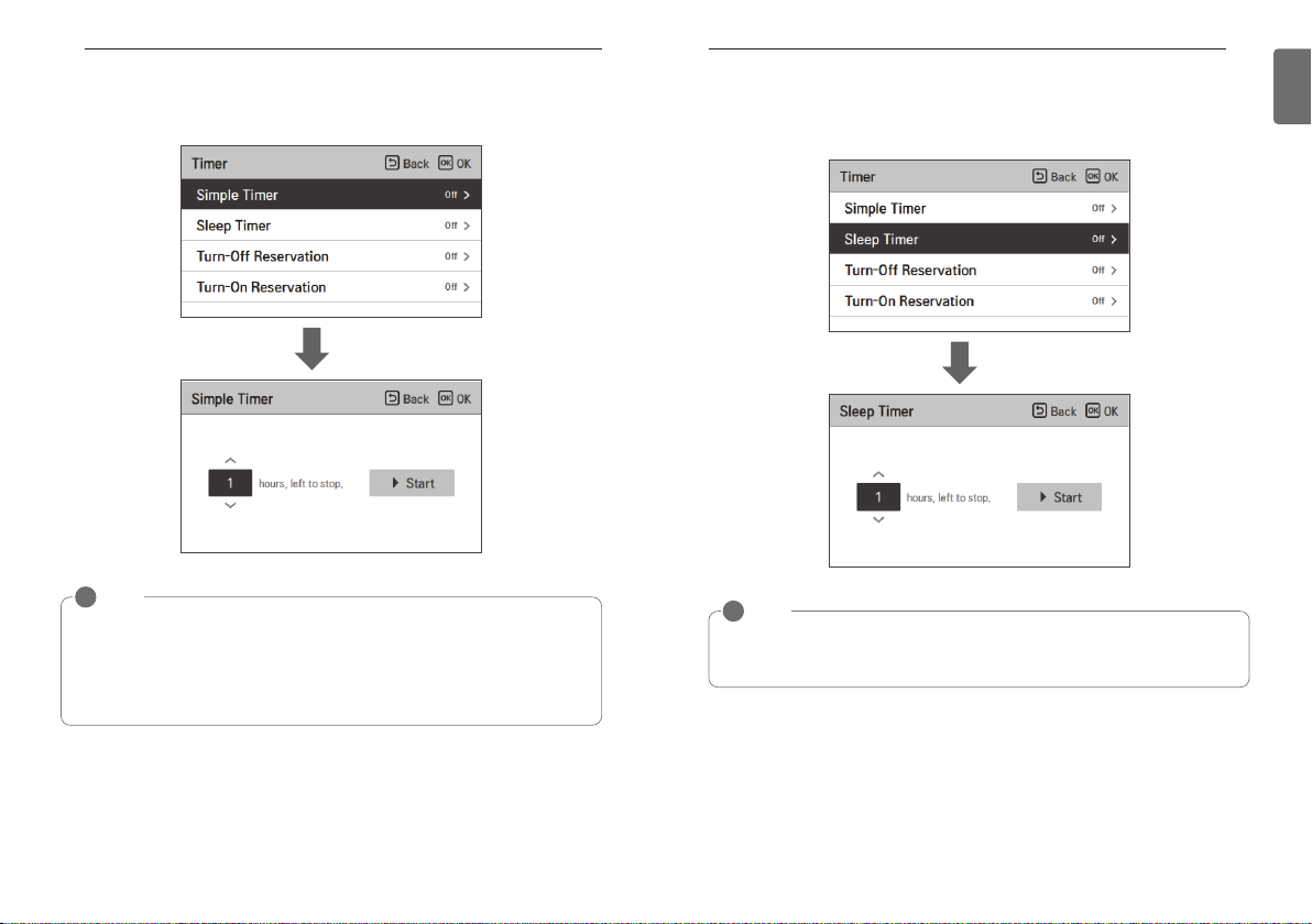
Simple timer
You can easily set the timer in the range of 1~7 hours in the units of 1 hour.
TIMER SETTING
Sleep timer
Sleep timer is the function to operate the air conditioner in sleep mode before going to sleep for
certain hours and stop the operation.
45
ENGLISH
OK
NOTE
!
If the product operation is On, the easy timer turns off the operation after the corresponding
time.
If the product operation is Off, the easy timer turns on the operation after the corresponding
time.
If the easy timer operation is turned On/Off before the timer operation, the set timer will be
cleared.
OK
NOTE
!
You can set the sleep timer while the product is in operation.
If the sleep timer operation is turned On before the timer operation, the set timer will be
cleared.

TIMER SETTING
46
Turn-off Reservation
The product is automatically turned Off at the set timer time.
Turn-on Reservation
The product is automatically turned On at the set timer time.
TIMER SETTING
47
ENGLISH
OK
NOTE
!
Even if the Turn-off Reservation operation is turned On/Off after the setting and before the
timer operation, the set timer is not cleared.
OK
NOTE
!
Even if the Turn-on Reservation operation is turned On/Off after the setting and before the
timer operation, the set timer is not cleared.
SCHEDULE SETTING
48
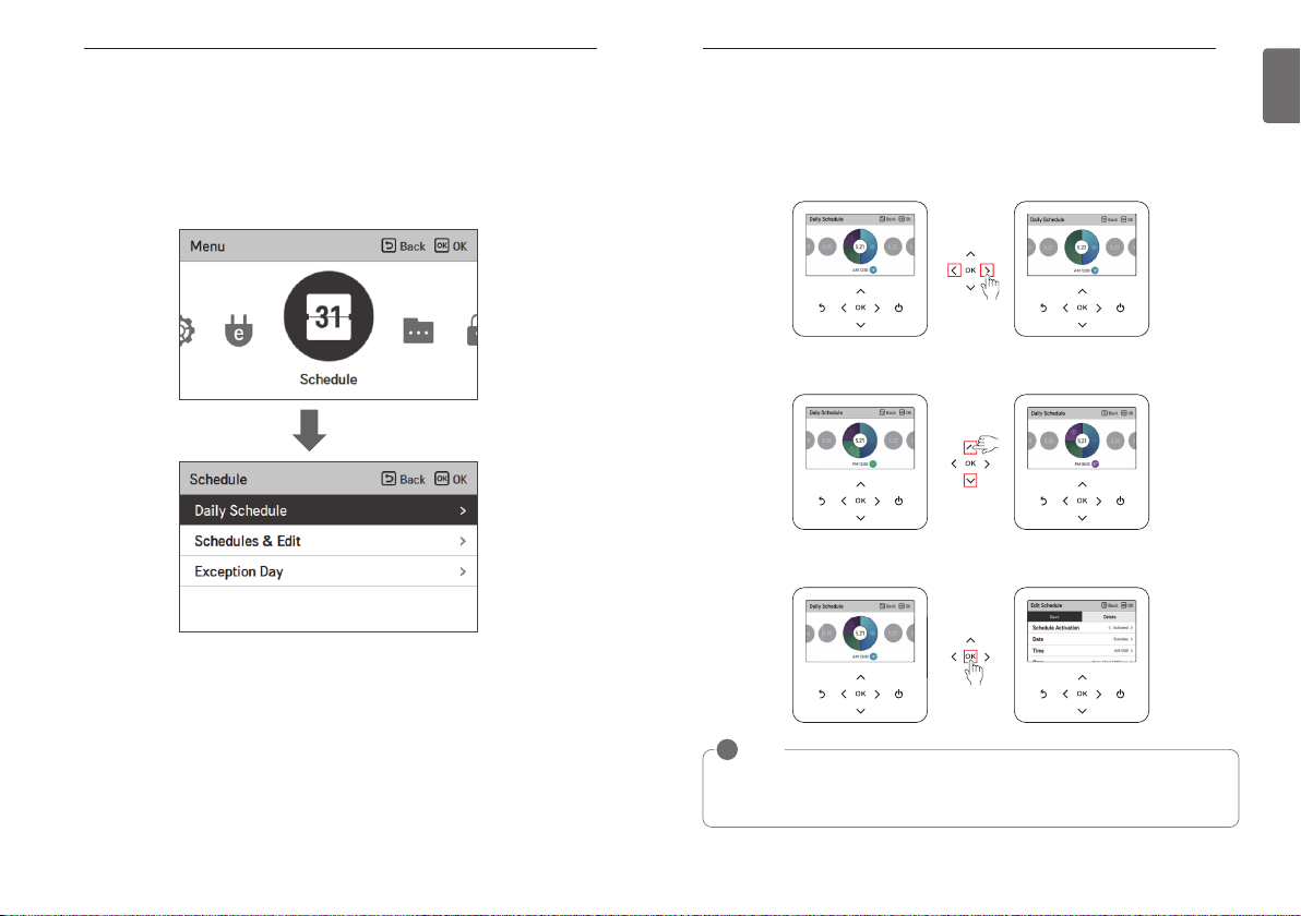
SCHEDULE SETTING
How to enter schedule
• In the menu screen, press [<,>(left/right)] button so select the schedule category, and press
[OK] button to move to the schedule setting list screen.
• In the schedule setting list screen, press [∧,∨(up/down)] button to select the menu to set, and
press [OK] button to move to the detail screen.
OK
SCHEDULE SETTING
Daily Schedule
It is the function that can check the status of the timer (schedule) saved in the remote controller.
• In the schedule list, select the daily schedule status category, and press [OK] button to move to
the detail daily schedule status screen.
• You can use the remote controller’s [<,>(left/right)] button to check the timer information of
other dates.
• You can use the remote controller’s [∧,∨(up/down)] button to check the corresponding date’s
other timer information.
• Select the timer information, and press [OK] button to move to the corresponding timer’s edit
screen.
49
ENGLISH
NOTE
!
In the daily schedule status screen, even if the timer (schedule) is set, if the corresponding
date is designated as an exception date, the schedule will not be performed.
Less than 5 schedules per day is recommended.

SCHEDULE SETTING
50
Schedules & Edit
It is the function that can check the status of the timer (schedule) saved in the remote controller.
• In the schedule list, select the daily schedule status category, and press [OK] button to move to
the daily schedule status detail screen.
• You can use the remote controller’s [<,>(left/right)] button to check other date’s timer information.
You can check the set
timer’s operation information (operation
On/Off, operation
mode, desired temperature), timer time, period,
and day of week.
• You can edit the saved schedule’s timer information.
- Select the schedule to edit using [∧,∨(up/down)] button, and press [OK] button to move to
the edit screen.
• Select the timer information, and press [OK] button to move to the corresponding timer’s edit
screen.
Schedules & Edit – Add schedule
Description of each stage in Add schedule
Stage 1. Period setting Stage 2. Day of week setting
Stage 3. Time setting Stage 4. Operation setting
Add schedule is completed
SCHEDULE SETTING
51
ENGLISH
< If schedule is changed > < If schedule is deleted >
In ‘Stage 1’, it sets the period to perform the timer.
In ‘Stage 2’, it sets the day of week to perform the timer.
- You can select ‘Everyday / Weekend / Weekdays / Individual selection’.
In ‘Stage 3’, it sets the start time for the timer.
In ‘Stage 4’, it sets the timer operation information.
- If ‘Stop’ is selected, you cannot set the mode / temperature / fan speed.
When stages 1~4 are completed, along with the message of ‘schedule is added’, it moves to
View and edit schedule screen.

SCHEDULE SETTING
52
Exception day
It is the function to automatically stop the operation on the set timer day.
• In the schedule list, select the exception day category, and press [OK] button to move to the
Exception day designation detail screen.
• In the exception day, you can check, and add/change/delete the exception day information
saved in the remote controller.
- To add an exception day, in the Exception day registration detail screen, designate
year/month/day, and press [OK] button to save the Exception day.
- Select the Exception day to edit using [∧,∨(up/down)] button, and press [OK] button to move
to the edit screen.
- In the exception day edit screen, you can check, delete/change the corresponding exception
day’s setting contents.
- When you change the exception day information, you need to save it after the change.
ENERGY
ENERGY (air conditioner / DX ventilator)
How to enter energy
• In the menu screen, press [<,>(left/right)] button to select the energy category, and press [OK]
button to move to the energy list.
OK
53
ENGLISH

ENERGY
54
Instantaneous power check
It is the function that can check the product’s instantaneous power.
※There may be some error with the actual instantaneous power, so use it only for reference.
• In the energy list, select the “Instantaneous power” category, and press [OK] button to move
to the detail screen.
OK
• The target and the value of all can be set in the energy setting.
• The usage ratio compared to the target is the value expressed in current/target * 100.
※For how to set the energy, refer to the energy setting.
ENERGY
Energy consumption
You can check the energy consumption (operation time, power consumption).
※There may be some error with the actual consumption, so use it only for reference.
• In the energy list, select the “energy consumption” category, and press [OK] button to move to
the detail screen.
OK
• In the detail screen, press [<,>(left/right)] button to move to the power consumption and operation time screen.
55
ENGLISH
NOTE
!
Instantaneous power: It is the power currently used in the product.
<, >
ENERGY
56
• Operation time unit is time (hr.), and power consumption unit is kWh.
• The power consumption display can be checked when it is connected to the indoor unit that
supports the power consumption information display function.
List
Year On Year Usage
Weekly usage
Monthly usage
Yearly usage
Power consumption Operation time
You can see the power consumption compared to the same month
of the previous year.
It displays the daily power consumption of the current month.
It displays the weekly power consumption of the current month.
It displays the monthly power consumption of the current year.
Description
You can see the operation time
compared to the same month of
the previous year.
It displays the daily operation time
of the current month.
It displays the weekly operation
time of the current month.
It displays the monthly operation
time of the current year.
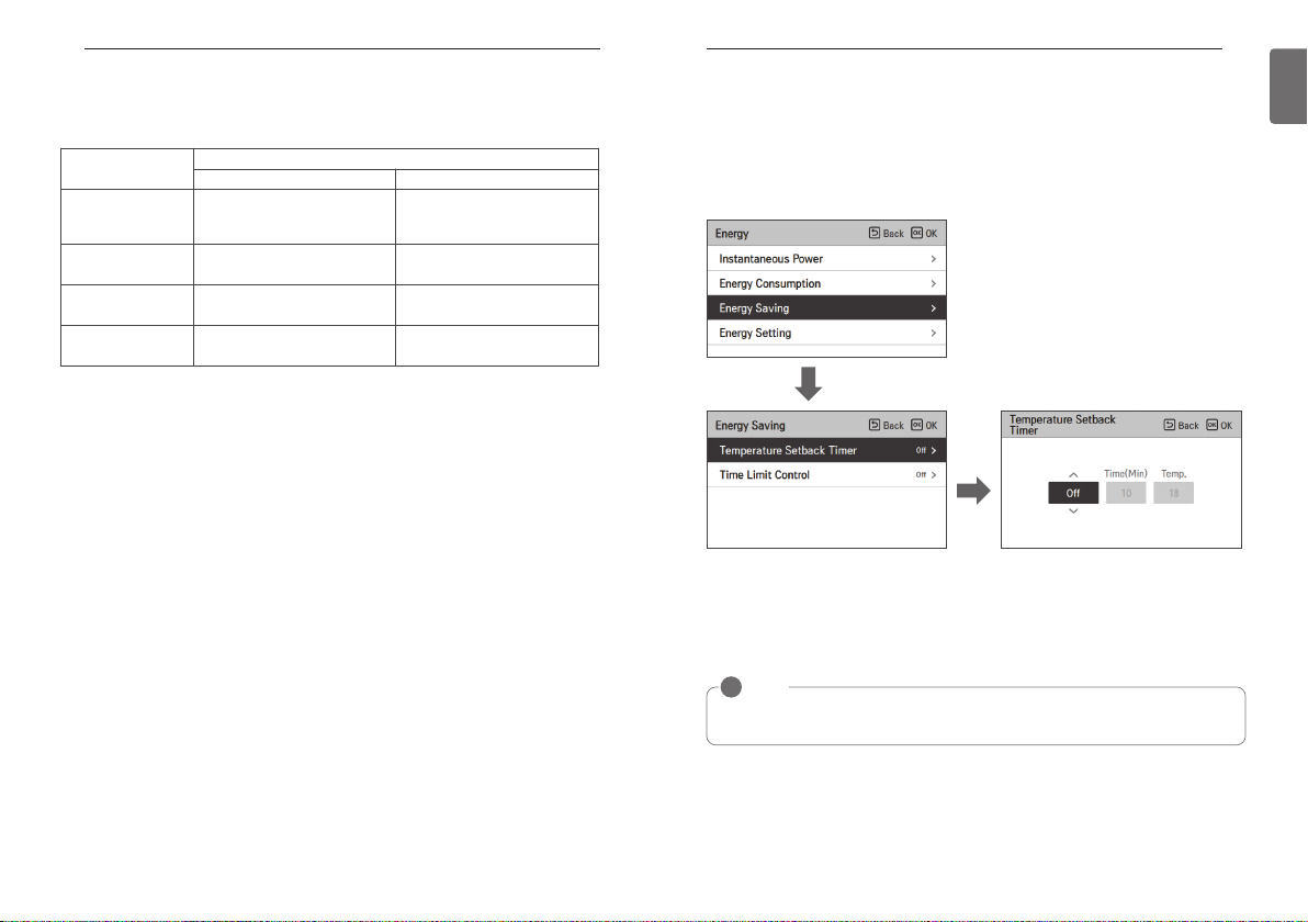
ENERGY
Energy saving - Temperature Setback Timer
It is the function to return to the desired temperature after the set time after the product operation for energy saving.
• In the energy list, select “Energy saving” category, and press [OK] button to move to the energy saving screen.
• In the energy saving list, select “Temperature Setback Timer” category, and press [OK] button
to move to the Temperature Setback Timer setting screen.
OK
OK
• When it is set to On, you can set the time (10 minutes ~ 120 minutes, 10 minutes unit) and the
temperature (18°C ~ 30°C), and after the setting, when you press [OK] button, the set value is
saved.
• When the desired temperature setback timer setting is set to “On”, after the set time, the desired temperature is recovered to the set temperature.
57
ENGLISH
NOTE
!
When it is set at the same time with the remote controller desired temperature range lock or
the central control temperature range lock, it may not return to the desired temperature.

ENERGY
58
Energy saving - Time Limit Control
It is the function to stop the product operation after the set time after starting the product operation for the energy saving.
• In the energy saving list, select “time limit control” category, and press [OK] button to move to
the time limit control setting screen.
ENERGY
Energy setting - outdoor unit capacity setting
It is the function that can set the outdoor unit capacity.
• In the energy list, select “energy setting” category, and press [OK] button to move to the energy setting screen.
• In the energy setting list, select “outdoor unit capacity setting” category, and press [OK] button
to move to the outdoor unit capacity setting screen.
59
ENGLISH
OK
OK
• In the detail screen, you can select “On/Off” to turn on and off the time limit control function.
When it is set to On, you can set the time (30 minutes ~ 540 minutes, 30 minutes unit), and
after the setting, if you press [OK] button, the set value is saved.
If you do not press [OK] button but press [Back] button, it moves to the list screen without saving the set value.
• If the time limit control is set to “On”, the operation stops after the set time.
NOTE
!
If it is set at the same time with the remote controller operation lock, the time limit control
will not be performed.
OK
OK
• In the detail screen, you can select “On/Off” to set the outdoor unit capacity. If it is set to On,
you can set the outdoor unit capacity (minimum 1kW), and after the setting, if you press [OK]
button, the set value is saved. If you do not press [OK] button but press “Back’ button, it
moves to the list screen without saving the set value.
• If the capacity setting is set to “On”, in the Instantaneous power screen, it is displayed as “all”
capacity.
• For the outdoor unit capacity, refer to the label of the outdoor unit product.
- For Single product and Multi product, the first 3 digits of the model name is the outdoor unit
capacity.
ex) For ABC1019…, it is 10.1kW
- For Multi-V product, the first 2 digits of the model name < 0.75 is the outdoor unit capacity.
ex) For ABCD101.…, it is 10 * 0.75 = 7.5kW
• For TMS users, refer to the all capacity displayed on TMS.
NOTE
!
According to the user input, there may be difference to the actual product capacity.

ENERGY
60
Energy setting - target instantaneous power setting
It is the function that can set the Instantaneous power’s target value.
You can set the target value to find the power consumption status.
• In the energy setting list, select “target Instantaneous power” category, and press [OK] button
to move to the target Instantaneous power setting screen.
ENERGY
Energy setting - target power consumption
It is the function to set the target power consumption per hour.
• In the energy setting list, select “target power consumption” setting category, and press [OK]
button to move to the target power consumption setting screen.
61
ENGLISH
OK
OK
• In the detail screen, you can select “On/Off” to set the target Instantaneous power.
If it is set to On, you can set the target Instantaneous power (minimum 1kW), and after the
setting, if you press [OK] button, the set value is saved.
- If the outdoor unit capacity is set, the maximum value is the outdoor unit capacity
- If the outdoor unit capacity is not set, the maximum value is 9999kW
If you do not press [OK] button but press “Back’ button, it moves to the list screen without
saving the set value.
• When the target Instantaneous power setting is set to “On”, in the Instantaneous power
screen, it is displayed as “all” capacity.
OK
OK
• In the detail screen, you can select “On/Off” to set the target power consumption.
When it is set to On, you can set the target power consumption (minimum 1kWh, maximum
100kWh), and after the setting, if you press [OK] button, the set value is saved.
If you do not press [OK] button but press “Back’ button, it moves to the list screen without
saving the set value.
• If the target power consumption setting is set to “On”, it is displayed as the energy
consumption’s power consumption target value.
- Daily target consumption: Weekly usage’s daily target
- Weekly target consumption: Monthly usage’s weekly target (daily target * 7)
- Monthly target consumption: Yearly usage’s monthly target (daily target * 31)

ENERGY
62
Energy setting - target operation time
It is the function that can set the Instantaneous power’s target value.
You can find the power consumption status by setting the target value.
• In the energy setting list, select “target operation time” category, and press [OK] button to
move to the target operation time setting screen.
OK
OK
• In the detail screen, you can select “On/Off” to set the target operation time.
When it is set to On, you can set the target operation time (minimum 1hr. and maximum 24hr.),
and after the setting, if you press [OK] button, the set value is saved.
If you do not press [OK] button but press “Back’ button, it moves to the list screen without
saving the set value.
• If the target operation time setting is set to “On”, it is displayed as the energy consumption’s
operation time target value.
- Daily target : Weekly usage’s daily target
- Weekly target : Monthly usage’s weekly target (daily target * 7)
- Monthly target : Yearly usage’s monthly target (daily target * 31)
ENERGY
Energy setting - Alarm Popup Setting
It is the function to set whether to use the target power consumption and the target operation
time notice popup window.
• In the energy setting list, select “target operation time” category, and press [OK] button to
move to the target operation time setting screen.
• In the notice popup list, select “target power consumption notice or target operation time notice” category, and press [OK] button to move to the detail setting screen.
OK
OK
OK
• You can set the notice popup as “daily”, “weekly”, “monthly”.
After the setting, if you press [OK] button, the setting is saved and moves to the previous
screen.
• When the target power consumption notice is set to “On, daily”
If the daily target power consumption’s 80%, 90%, 95%, and 100% power is used a day, the
popup screen appears.
• When the target operation time notice is set to “On, daily”
When the product is operated at the daily target operation time’s 80%, 90%, 95%, and 100%,
the popup screen appears.
NOTE
!
The popup message appears once every hour.
63
ENGLISH

ENERGY
64
Energy setting – Usage data initialization
It is the function to initialize all of the power consumption and operation time information.
• In the energy setting list, select “consumption data initialization” category, and press [OK] button to move to the consumption data initialization setting screen.
OK
OK
OK
• In the initialization popup screen, if you press “check” button, all previously saved power consumption and operation time are deleted.
FUNCTION SETTING
FUNCTION SETTING
How to enter function setting
To enter the menu displayed at the bottom, you need to enter the function setting menu as follows.
• In the menu screen, press [<,>(left/right)] button to select the setting category, and press [OK]
button to move to the setting list.
• In the setting list, select the function setting category, and press [OK] button to move to the
function setting list.
OK
65
ENGLISH

FUNCTION SETTING
66
Function Setting Vane angle control setting
Menu Description
Vane angle control setting
Elevation grill setting
Robot cleaning setting
Auto dry setting
Filter sign check and
initialization
Change Temperature
setting
Dead Band
Wi-Fi pairing
Zone Name setting Zone name settings allow you to select zone name.
Override set time setting When timed override is used, the set time will be a default value.
Home leave set
temperature setting
Comfort cooling setting
ODU Refrigerant Noise
Reduction setting
Defrost Mode setting It is the function to set the outdoor unit’s defrost mode operation.
Smart load control
setting
Low noise mode time
setting
Advanced fan speed “Auto”
Delay time setting
(exclusive for ventilation)
Midnight air cooling
(ventilation interface)
Human detection mode It is the function to set the operation of human detection mode.
Discharge direction
CO2 fan control
Economizer setting
You can control the wind blowing angle.
It is the function to operate the Elevation grill for the indoor unit filter cleaning.
Robot cleaning function is the function to automatically perform the filter
cleaning with the cleaner of the product when the air conditioner is used for
certain time period. It sets the manual or automatic operation of the robot
cleaning. You can set it 30 seconds after the stopping of the operation.
Auto dry function is the function to remove mold and moisture by drying the inside
of the indoor unit after the cooling operation and when the product is turned off.
When it becomes the time for the indoor unit filter cleaning, the filter
cleaning display appears, and it is the function to remove the display.
Change Temperature is the function to set the temperature for the
automatic conversion between cooling and heating according to the
temperature in AI operation mode.
When heating and cooling desired temperatures have been changed,
the set value will maintain a difference between the heating and
cooling desired temperature.
It is the function to perform the pairing function of the Wi-Fi module
connected to the indoor.
When customer operate as home leave mode, this setting
temperature value will be applied.
It is the function to set the outdoor unit Comfort saving operation stage value.
It is the function to set the outdoor unit’s refrigerant noise reduction
function.
It is the function to set the outdoor unit’s smart load control stage value.
(Smart load control is the function to calculate the necessary performance
with the indoor and outdoor air temperature and humidity and operate.)
It is the function to set the start and end time of the outdoor unit’s
low noise mode operation.
It is the function to set the indoor unit’s fan auto by temperature.
It is the function to set the ventilation operation to start after the delay
time.
It is the function to discharge indoor air and supply cool outdoor air
into the indoor during summer nights to save energy.
This is a function to set the usage of the upper and lower vanes when
operating the product.
A function that controls the fan when the product is turned ON/OFF,
based on the CO2 concentration in the ventilation product.
Provides outside air to a room to save energy and improve the air
quality indoors.
You can control the wind blowing angle.
- In the function setting list screen, press [∧,∨(up/down)] button to select the vane angle control
category, and press [OK] button to move to the up/down vane angle detail screen.
• In the detail screen, press [∧,∨(up/down)] button to select “individual control, overall control,
standard”.
• Use [<,>(left/right)] button to select the vane.
- The selected vane is moving. Check the moving vane.
• Press [∧,∨ (up/down)] button to select the desired wind angle, and press [OK] button to save
the setting.
- The wind angle’s setting range can be changed to 5 stages or 6 stages according to the product.
※If you do not press [OK] button, the selected wind angle will not be reflected.
Control Description
Each It sets the vane angle individually.
All It sets the vane angle of all the vanes of the product at once.
Standard It sets the vane angle to the factory initialization state.
NOTE
!
For some product types, there are products with only 1 or 2 vanes.
OK
FUNCTION SETTING
67
ENGLISH

FUNCTION SETTING
68
Elevation grill setting
It is the function to operate the Elevation grill for the indoor unit filter cleaning.
- While the product operation is stopped, if you use [<,>(left/right)] button to select the setting
value, the grill operation status changes.
Value Description
Up Raises the Elevation grill toward the product
Stop Stops the movement of the Elevation grill
Down Lowers the Elevation grill toward the floor
NOTE
!
The Elevation grill setting function may not work in some products.
FUNCTION SETTING
Robot cleaning setting
Robot cleaning function is the function to perform the automatic filter cleaning with the cleaner
of the product when the conditioner is used for certain period of time. It sets the manual or automatic operation of the robot cleaning.
- It can be set 30 seconds after the operation stop.
• You can use [<,>(left/right)] button to set the following setting values as follows.
Value Description
Auto
Manual It manually performs the robot cleaning.
NOTE
!
The robot cleaning setting function may not work in some products.
It automatically performs the robot cleaning when the accumulated indoor unit operation time passes 30 hours
Auto dry setting
Auto dry function is the function to remove mold and moisture by drying inside the indoor unit
after the cooling operation and when the product is turned off.
• You can use [<,>(left/right)] button to set the following setting values as follows.
69
ENGLISH
Value Description
Use Use auto dry function
Not Use Not use auto dry function
NOTE
!
Auto dry setting function may not work in some products.

FUNCTION SETTING
70
Filter sign check and initialization
When it becomes the time for the indoor unit filter cleaning, the filter cleaning message appears,
and it is the function to remove the message.
• In the function setting list, select the Filter sign check and initialization category, and press [OK]
button to display the detail screen.
OK
Filter sign Description
Good Usage time is 70% or less
Normal Usage time is 71~80%
Caution Usage time is 81~99%
Bad Usage time is 100%
- When it becomes time to the filter clean, “Filter cleaning or replacement is required.” message
is displayed. Enter the Filter sign check and initialization detail screen.
- If the product has the function to display the time remaining until the filter cleaning, even if the
filter cleaning message is not displayed, you can enter the Filter sign check and initialization.
- If there is a remaining time display function, when you enter the Filter sign detail screen, you
can see the consumption and the remaining time.
NOTE
!
• Some products have a Filter Time Remaining function that can be accessed with Filter Sign
check.
• Dirty filters will increase the cost to cool or heat the conditioned space.
• The filter check message is cleared after certain time without a separate clearing.
FUNCTION SETTING
Change temperature setting
Change Temperature is the function to set the automatic Change Temperature between cooling
and heating operation according to the temperature in AI operation mode.
• In the function setting list, select the Change Temperature category, and press [OK] button to
move to the detail screen.
OK
Value
1~7°C(Default : 2°C)
It is the function that can be used only in cooling/heating product.
Example of using Change Temperature
Condition
1) Mode: AI mode
2) temperature: 22°C
3) Change Temperature: 3°C → Change Temperature 3°C difference
※In case of the above conditions, it operates as in the graph.
Temp(ഒ)
ڸڸ
25ഒ
22ഒ
19ഒ
!
The Change Temperature setting function may not work in some products.
ڹ
NOTE
ڸ : Cooling operation start
ڹ : Heating operation start
71
ENGLISH

FUNCTION SETTING
72
Dead Band
Dead Band function is used with a dual setpoint mode.
When heating and cooling desired temperatures have been changed, the set value will maintain a
difference between the heating and cooling desired temperature.
• In the function setting list, select the dead band category, and press [OK] button to move to the
detail screen.
OK
NOTE
!
Dead Band function only can use in dual setpoint mode.
• When changing the desired cooling temperature, in case of that the difference with the
heating temperature becomes lesser than its minimal value of difference, it lowers the
desired heating temperature automatically.
• When changing the desired heating temperature, in case of that the difference with the
heating temperature becomes lesser than its minimal value of difference, it raises the
desired cooling temperature automatically.
FUNCTION SETTING
Wi-Fi pairing setting
It is the function to perform the pairing function of the Wi-Fi module connected to the indoor unit.
• In the function setting list, select the Wi-Fi pairing category, and press [OK] button to move to
the detail screen.
- After selecting “Apply”, if you press [OK] button, the Wi-Fi pairing popup window is created,
select “check” and press [OK] button to request the Wi-Fi pairing.
OK
NOTE
!
The Wi-Fi setting function may not work in some products.
73
ENGLISH

FUNCTION SETTING
74
Zone Name setting
Zone name settings allow you to select zone name.
FUNCTION SETTING
Override Set Time Setting
Override Set Time function can only be used in Dual Setpoint Control mode.
When timed override is used, the set time will be a default value.
75
ENGLISH
OK
OK
NOTE
!
Zone name setting function may not work in some indoor unit products.
OK
NOTE
!
Override Set Time function can only be used in a dual setpoint control mode.

FUNCTION SETTING
76
Home Leave Set Temperature Setting
Home Leave Set Temperature function is used in Dual Setpoint Control mode.
When customer operate as home leave mode, this setting temperature value will be applied.
OK
NOTE
!
Home Leave Set Temperature function can only be used in a dual setpoint control mode.
FUNCTION SETTING
Comfort cooling setting
It is the function to set the outdoor unit Comfort saving operation value.
• You can set the following values using [<,>(left/right)] button.
Value
Step 1
Step 2
Step 3
NOTE
!
The Comfort cooling function does not work in the group control.
Comfort cooling setting function is only available in some products.
ODU Refrigerant Noise Reduction setting
It is the function to set the outdoor unit’s refrigerant noise reduction function.
• You can use [<,>(left/right)] button to set the following setting values as follows.
77
ENGLISH
Value Description
Step 0 Not use
Step 1 Outdoor unit noise mode 1
Step 2 Outdoor unit noise mode 2
NOTE
!
The ODU Refrigerant Noise Reduction function can be set only when the installer setting’s
outdoor unit function M/S setting is set to “Master”.
ODU Refrigerant Noise Reduction function is only available in some products.

FUNCTION SETTING
78
Defrost mode setting
Change the outdoor unit’s defrost mode operation.
• Select value using [<,>(left/right)] button.
FUNCTION SETTING
Smart load control(SLC) setting
Change the outdoor unit’s Smart Load Control stage value.
(Smart load control is the function to calculate the indoor air temperature, outdoor air temperature, and humidity to operate effectively.)
• In the function setting list, select the Smart load control category, and press [OK] button to
move to the detail screen.
79
ENGLISH
Step 0 Not use
Value
NOTE
!
The Defrost mode setting function can be set only when the installer setting’s outdoor unit
function M/S setting is set to “Master”.
Defrost mode setting function is only available in some products.
Step 1 Forced snow removal
Step 2 Quick defrost
Step 3 Forced snow removal + quick defrost
OK
Off Step 0
Value
- When SLC is Operating, on the expanded screen’s monitoring information, ‘In Smart load con-
trol’ is displayed.
NOTE
!
Smart load control function can be set only when the installer setting’s outdoor unit function
M/S setting is set to “Master”.
Smart load control function is only available in some products.
Step4 settings may not be available on some indoor unit products.
On
Step 1
Step 2
Step 3
Step 4

FUNCTION SETTING
80
Low noise mode time setting
It is the function to set the start and end time of the outdoor unit’s low noise mode operation.
• In the function setting list, select the Low Noise Mode Time category, and press [OK] button to
move to the detail screen.
- After setting the start time and the end time, press [OK] button to move to the upper level
list.
- If the start time and the current time are the same, it enters the outdoor unit low noise opera-
tion mode, and in the monitoring screen, ‘in outdoor unit low noise operation mode’ message
is displayed.
- If the end time and the current time are the same, the outdoor unit low noise operation mode
is cleared.
OK
FUNCTION SETTING
Advanced fan speed “Auto” setting
It is the function to set the indoor unit’s temperature based auto fan usage.
It is the function to automatically change the fan speed according to the difference between the
indoor temperature and the desired temperature.
• You can set the following setting values using [<,>(left/right)] button.
Value Description
Set Change the fan speed automatically
Clear Do not change the fan speed automatically
NOTE
!
Advanced fan speed “Auto” setting function is only available in some products.
81
ENGLISH
NOTE
!
Low noise mode time setting function can be set only when the installer setting’s outdoor
unit function M/S setting is set to “Master”.
Low noise mode time setting function is only available in some products.
CAUTION
!
If the function is not used, please set it to Off.
When you enter the low noise operation, the cooling capacity may be degraded.

FUNCTION SETTING
82
Delay time (exclusive for ventilation)
It is the function to set the ventilation operation to start after the delay time.
• In the function setting list, select the delay time category, and press [OK] button to move to the
detail screen.
- After setting the minute, press [OK] button to move to the upper level list.
FUNCTION SETTING
Midnight air cooling (ventilation interface)
It is the function to discharge indoor air and supply cool outdoor air into the indoor during summer nights to save energy.
• In the function setting list, if you select midnight outdoor air cooling category and press [OK]
button, it moves to the detail screen.
- When you set the start and end time and press [OK] button, it saves and moves to the upper
level list.
83
ENGLISH
OK
Value
0 ~ 60 Minutes
OK
NOTE
!
Whether to run the midnight air cooling is decided only when both air conditioner and
ventilation are stopped.
• Even if it is the set midnight air cooling time, it enters the midnight air cooling only when
the outdoor temperature conditions is met.
• During the midnight air cooling operation, “in midnight outdoor air cooling” message is
displayed on the monitoring screen.
• Midnight air cooling function may not work in some products.
CAUTION
!
If you do not use the function, please set it as off.

FUNCTION SETTING
84
Human detection mode setting
It is the function that enables energy saving through the human detection power saving operation
and wind direction setting.
In the function setting list, select human detection operation mode category and press [OK] button to move to the lower level setting list.
OK
After selecting human detection power saving mode category, if you press [OK] button, it moves
to the detail screen.
FUNCTION SETTING
After selecting human detection wind direction category, you can set the following setting values
using [<,> (left/right)] button.
Value Description
OFF Do not use human detection wind direction control
Direct Human detection direct wind operation
Indirect Human detection indirect wind operation
NOTE
!
Human detection operation setting function may not work in some products.
Discharge direction
This is a function to set the usage of the upper and lower vanes when operating the product.
You can set the following setting values using [<,>(left/right)] button.
85
ENGLISH
You can select OFF ← → On/Off Power saving ← → Temperature power saving for mode value.
You can set the time value when you select On/Off power saving or Temperature power saving.
Discharge
direction
NOTE
!
Discharge direction setting function may not be available on some products.
Concurrency (whole)
Top
Bottom
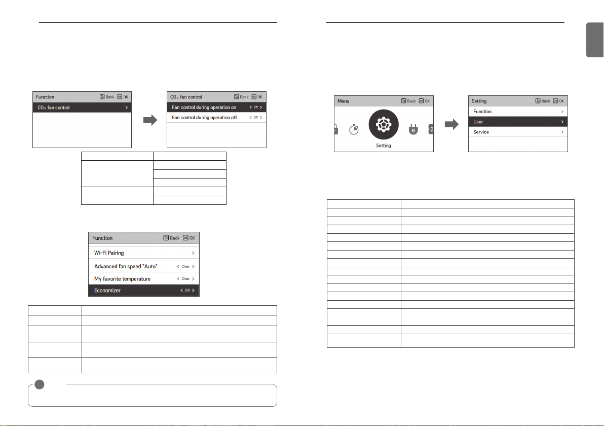
FUNCTION SETTING
86
CO2 Fan Control(general ventilator)
A function that controls the fan when the product is turned ON/OFF, based on the CO2
concentration in the ventilation product.
1.
After selecting “CO2 fan control” in the Function settings list, press the [OK] button to go to the detail screen.
2. After selecting “Fan control during operation on” or “Fan control during operation off” in the "
CO2 Fan Control" list, you can set the following values using [<,>(left/right)] button.
USER SETTING
USER SETTING
How to enter user setting
To enter the menu displayed at the bottom, you need to enter the user setting menu as follows.
• Select the setting category, and press [OK] button to move to the setting list.
• Select the user setting category, and press [OK] button to move to the user setting list.
87
ENGLISH
OK
Condition 1 Condition 2
Operation on
Operation off
Off
Low
Periodic
Off
Periodic
Economizer setting
Provides outside air to a room to save energy and improve the air quality indoors.
Value Description
Off
Auto
Step 1
Step 2
NOTE
!
Economizer setting function may not be available on some products.
Disable the economizer function to keep the outside air damper closed.
If the outside air temperature is lower than the air temperature indoors when
cooling is being operated, outside air is supplied to the room to save energy.
Opens the outside air damper opening by one stage to improve the indoor
air quality by introducing fresh air into the room.
Opens the outside air damper opening by two stages to improve the indoor
air quality by introducing fresh air into the room.
OK
User Setting
• You can set the product user functions.
• Some functions may not be available in some product types.
Menu Description
Language setting Set the language to be displayed on the remote controller.
Setpoint Type Setting It is the function to set GUI type on the remote controller.
Temperature unit setting Set the temperature unit displayed on the remote controller.
Screen saver timer setting Adjust the screen Off time of the remote controller.
LCD brightness in idle setting Adjust the remote controller’s screen brightness.
External device setting Set the name of external equipment and equipment logic setting
Date setting Set the date displayed on the remote controller.
Time setting Set the time displayed on the remote controller.
Summer time setting Set the summer time in the remote controller.
Password setting
Schedule initialization Initialize all timer settings in the remote controller.
Theme setting Set the theme of the remote controller screen.
Humidity display
System reboot Restart the remote controller.
Indoor unit display light
brightness
Set the password to prevent unauthorized change to remote controller settings.
It is the function to decide whether to display humidity on the main
screen and additional information screen.
This function adjusts the brightness of the indoor unit display light.

USER SETTING
88
Language setting
Set the language to be displayed on the remote controller.
• In the user setting list, select the language category, and press [OK] button to move to the detail screen.
• After the setting, if you press [OK] button, the setting is saved and moves to the previous
screen.
OK
Language
한국어
Deutsche Italiano Español
Русский Polski Português
中文
English Français
Čeština
USER SETTING
Setpoint Type Setting
It is the function to set GUI type on the remote controller.
* Dual setpoint type is a function that makes it possible to set the cooling and heating target tem-
perature simultaneously. It is recommended for customers accustomed to using North American thermostats.
We recommend that you use it only in the region (North America).
If select dual setpoint option, target temperature ranges will be expanded and activated override, home leave, hold mode and occupancy information based schedule.
<Dual setpoint> <Single setpoint>
89
ENGLISH

USER SETTING
90
Temperature unit setting
Set the temperature unit displayed on the remote controller.
• In the user setting list, select the temperature unit setting category, and press [OK] button to
move to the detail screen.
Screen saver timer setting
Adjust the screen Off time of the remote controller.
• Select the following setting values using [<,>(left/right)] button.
USER SETTING
91
ENGLISH
OK
Value
CAUTION
!
The temperature unit function may not work or work differently in some products.
You cannot set the temperature unit in the slave wired remote controller.
Celsius
Fahrenheit
1°C
0.5°C
15sec 30sec (default) 1min
CAUTION
!
Selecting longer stand by screen will decrease LCD lifespan.
Value
LCD brightness in idle setting
Adjust the remote controller’s screen brightness.
• Select the following setting values using [<,>(left/right)] button.
0% 10% (default) 20% 30% Auto
CAUTION
!
Selecting brighter stand by screen will decrease LCD lifespan.
※ "Auto" setting is only available in the indoor units that is equipped with the human detection
sensor.
※ When set to Auto, wired remote standby screen brightness (0%, 10%, 20%, 30%) will auto-
matically adjust according to the illuminance detected by the human detection sensor.
Value

USER SETTING
92
External device setting
Set the name of external equipment and equipment logic setting
• In the user setting list, select the external device setting category, and press [OK] button to
move to the detail screen.
OK
External device use
• In the external device setting list, select “External device use” category, and press [OK] button
to move to the external device use setting screen.
- If external device use setting value is use, you can see the control unit of external device in
main screen.
USER SETTING
External device types
It is the function to set the name of the External device attached to the remote controller.
• You can set the following setting values using [<,>(left/right)] button.
Value
Motor Lighting Fan Heater Pump Others
93
ENGLISH
Not use Use
Value

USER SETTING
94
On condition / Off condition
It is the function to set to use the information managed by the wired remote controller as the
contact point control condition to widen the usage of the contact point (Digital Output) installed in
the remote controller.
• In the external device setting list, select the On/Off condition setting category, and press [OK]
button to move to the detail screen.
OK
Condition 1 Condition 2 Condition 3 Condition 4
None Deactivate - Deactivate
Aircon
Current Temp. 1°C~ 39.5°C
• The External device operates as the operation set in the conditions 1~3.
• If the External device is set to auto while both ON condition and OFF condition are not set, contact point OFF is output.
• If the ON condition and OFF condition are the same, it is finally processed as OFF condition.
On -
Off -
Cool mode -
Heat mode -
Fan mode -
Dry mode -
Auto mode -
Under
External device name On
External device name Off
Over
USER SETTING
Date setting
Set the date displayed on the remote controller.
• In the user setting list, select the date category, and press [OK] button to move to the detail
screen.
• After the setting, if you press [OK] button, the setting is saved and moves to the previous
screen.
OK
95
ENGLISH

USER SETTING
96
Time setting
Set the time displayed on the remote controller.
• In the user setting list, select the time category, and press [OK] button to move to the detail
screen.
• After the setting, if you press [OK] button, the setting is saved and moves to the previous
screen.
OK
USER SETTING
Summer time setting
Set the daylight savings time dates in the remote controller.
• In the user setting list, select the summer time setting category, and press [OK] button to
move to the detail screen.
- Summer time: The system to advance the time by 1 hour from the spring when the day is
longer and return back in the fall when the day gets shorter.
- When it becomes AM 02:00 on the DST start date, the current time changes to AM 03:00,
and when it becomes AM 02:00 of the DST end date, the current time changes to AM 01:00.
OK
97
ENGLISH

USER SETTING
98
Password setting
Set the password to prevent unauthorized change to remote controller settings.
• Select the user password setting category, and press [OK] button to move to the detail screen.
- If the password is set, when you enter “menu – setting”, you need to input password to
enter the setting list.
- When you forgot the password, you can initialize the password using the installer setting’s
“password initialization”.
The initialized password is “0000”.
OK
USER SETTING
Schedule initialization
Initialize all timer settings in the remote controller.
• In the user setting list, select the schedule initialization setting category, and press [OK] button
to move to the detail screen.
- Press the check button to initialize the sleep/simple timer, on/off timer, schedule and exception date in the remote controller.
OK
99
ENGLISH

USER SETTING
100
Theme setting
Set the theme of the remote controller screen.
• Select either white or black using [<,>(left/right)] button.
Humidity display
It is the function to decide whether to display humidity on the main screen and additional information screen.
You can use [<, > (left/right)] button to set the setting values (On or Off).
USER SETTING
System restart
Restart the remote controller.
• In the user setting list, select the system restart setting category, and press [OK] button to
move to the detail screen.
- In the detail screen, when you press [OK] button, a popup message is displayed, press the
check button, to restart the system.
- For forced reset, press down [On/Off + Back] button for 5 seconds to restart the system.
OK
101
ENGLISH
Setting value
NOTE
!
If humidity display is `ON`, the displayed humidity is different according to the humidity
detection location setting (installer setting).
• Remote controller: remote controller humidity display.
• Indoor unit: If it receives indoor unit humidity, it displays the indoor unit humidity, and if it
does not receive indoor unit humidity, it does not display humidity.
ON Display humidity.
OFF Do not display humidity.

USER SETTING
102
Indoor unit display light brightness setting
This function adjusts the brightness of the indoor unit display light.
• You can set the following setting values using [<,>(left/right)] button.
SERVICE SETTING
SERVICE SETTING
How to enter service setting
To enter the menu displayed at the bottom, you need to enter the service setting menu as follows.
• In the menu screen, press [<,>(left/right)] button to select the setting category, and press [OK]
button to move to the setting list.
• In the setting list, select the service setting category, and press [OK] button to move to the
service setting list.
OK
103
ENGLISH
On Off Auto
※ "Auto" setting is only available in the indoor units that is equipped with the human detection
sensor.
※ When set to Auto, the indoor unit display light brightness will automatically adjust according to
the illuminance detected by the human detection sensor.
※ "Off" setting is only available in the indoor units that have brightness control function.
Value
Service setting
• You can set the product service functions.
• Some functions may not be displayed/operated in some product types.
Menu Description
Service contact
Model Information
RMC Version Information Check the remote controller model name and software version.
Error History View the connected indoor unit’s error history.
Open Source License View the remote controller’s open source license.
Check and input the service center phone number that you can call
when there is service issue.
Check the indoor/outdoor product group and capacity information to
which the remote controller is connected.

SERVICE SETTING
104
Service contact
Check and input the service center phone number that you can call when there is service issue.
• In the service setting list, select the service contact point and press [OK] button to move to the
detail screen.
• While “edit” button is selected, press [OK] button to move to the edit screen, change it, and
press [OK] button to change the service contact point.
OK
OK
SERVICE SETTING
Model information
Check the indoor/outdoor product group and capacity information to which the remote controller
is connected.
• In the service setting list, select the indoor/outdoor model information category, and press [OK]
button to move to the detail screen.
• Indoor unit capacity
- 1kWh = 1kBtu * 0.29307
kWh is the result calculated based on Btu, There may be a small difference between calculated and actual capacity.
Ex) If the indoor unit capacity is 18kBtu, it is displayed as 5kWh.
OK
105
ENGLISH

SERVICE SETTING
106
RMC Version Information
Check the indoor/outdoor product group and capacity information to which the remote controller
is connected.
• In the service setting list, select the remote controller version information check category, and
press [OK] button to move to the detail screen.
SERVICE SETTING
Error history
View the connected indoor unit’s error history.
• In the service setting list, select ‘check error history’ category, and press [OK] button to move
to the detail screen.
- You can view up to 20 error instances sorted by date occurred.
107
ENGLISH
OK
OK

SERVICE SETTING
108
Open source license
View the remote controller’s open source license.
• In the service setting list, select the open source license category, and press [OK] button to
move to the detail screen.
INSTALLATION
INSTALLATION
Installation of Remote Controller
• After fixing the remote controller installation plate on the desired location, fix it firmly with the
provided screws.
- If the installation plate is not flat on the surface, it may result in the controller being twisted
and cause a defect.
- If there is a mounting box, install the remote controller installation plate using the fixings holes
which suit, as in the below diagrams.
- Do not leave a gap with the wall or product loose after the installation.
109
ENGLISH
OK
• The wired remote controller cable can be installed in 4 directions. Install to the suitable
direction according to the installation environment.
- Installation direction: Rear entry, top side, right side, left side.
- When you install the remote controller cable at the top, right and left side, remove the remote
controller cable guide hole before the installation.
※ Use a long nose pliers to remove the guide hole.
• After removing the hole, trim the cut surface neatly.
ڹ Top side guide groove
ںLeft side
guide
groove
ڸRear cable
entry
•
When installing the remote control cable on the left side, be sure to install it in the following guide.
ڹ Top side guide groove ڹ Top side guide groove
ڻRight side
guide groove
ڻRight side
guide
groove
ںLeft side
guide groove
1. Make the cable to "ㄱ" shape as shown below.
2. Fit the bent "ㄱ" cable into the upper center piece of case.
3. Tighten the installation plate with preventing interference with the surrounding guide structure.
※ If the cable is assembled in a shape other than "ㄱ", it may not be fastened to the installation
plate due to interference with the structure of case.
Reference. the bent cable shape The Upper center boss for fixing the bent cable

INSTALLATION
RED(12V)
YELLOW(SIG)
BLACK(GND)
YELLOW(SIG)
BLACK(GND)
YELLOW(SIG)
BLACK(GND)
OK
Indoor unit Main PCB
Indoor unit 1
Indoor unit 2 Indoor unit 3
Master Slave Slave
1
2
Master Slave Slave
GND
GND
12V
Signal cable
Signal cable
Black
Red
No. 3 switch OFF: master (factory ship-out based)
No. 3 switch ON: slave
YellowYellow
OK
110
• After fixing the remote controller top side on the installation plate attached to the wall as in the
following figure, press the bottom side to combine with the installation plate.
- Do not leave a gap in the top, bottom, left, and right side of the remote controller and the in-
stallation plate after combining them.
- Before combining with the installation plate, arrange the cables to avoid interference with the
circuit parts.
<Order of Combining>
Wall Wall
•
When you remove the remote controller from the installation plate, insert a small flat head screwdriver into the bottom side separation hole and turn clockwise to separate the remote controller.
- There are 2 separation holes at the bottom part. Slowly separate one by one.
- Be careful not to damage the internal parts during the removal.
<Order of Separation>
• Use the connection cables to connect the indoor unit with the remote controller.
DC 12 V Red
Signal Yellow
GND Black
OK
Please check if connector is normally connected.
Connecting cable
• For the following cases, separately purchase and use the cables suitable for the situation.
- Do not install the cable over 50 m. (It may cause communication issues.)
- If the distance between the wired remote controller and the indoor unit is 10 m or more : 10
m extension cable (model name: PZCWRC1)
- If you control several indoor unit products with one wired remote controller : Group control
cable (model name: PZCWRCG3)
NOTE
!
During the wired remote controller installation, do not bury it in the wall. (It may cause
temperature sensor failure.)
Do not install the cable over 50 m. (It may cause communication defect.)
When you install the extension cable, carefully check the direction of the connectors on the
remote controller side and the product side before the installation.
Specification of extension cable: AWG 24, 3 conductor or above.
Wall Side
Indoor
Unit side
INSTALLATION
Group control
• It connects and controls 2 or more air conditioner indoor units(Maximum number of IDU : 16ea)
to one wired remote controller.
※Connect using the group control cable.
① Group control cable (PZCWRCG3): Connect to indoor unit’s wired remote controller connector
② Extension cable (PZCWRC1): Connect to No. ① cable and slave indoor unit’s wired remote
controller connector
While No. ① cable is connected, connect No. ② cable.
NOTE
!
• Connect only GND and signal cable to the indoor unit set as slave. (If power cable is also
connected, it may cause loss of communication)
• Inquiries related to the purchase of the cable shall be directed to the specialized company
and the service center.
• After checking the existence of the event communication in the product manual, change
master/slave of the remote controller.
※For details, refer to ‘remote controller master/slave’ contents.
• Change master/slave of the indoor unit.
- For ceiling cassette and duct product group, change the setting with the indoor unit PCB
switch.
111
ENGLISH

INSTALLATION
112
- For the details on the wireless remote controller master/slave setting changes, refer to the
wireless remote controller manual.
- After completing the master/slave setting in the indoor unit product, turn Off the power of the
indoor unit product, and turn On the power after 1 minute.
NOTE
!
• During the group control, set only 1 indoor unit as master.
• During the group control, some functions other than the basic operation setting, fan speed
Low/Med/High, remote controller lock setting, and time setting may be limited.
• During the individual control, if the master indoor unit Dip switch is set to slave, malfunction
may occur.
INSTALLATION METHOD TO USE EXTERNAL DEVICE
INSTALLATION METHOD TO USE EXTERNAL
DEVICE
Cable connection method to use external device
1) Wired remote controller-cable connection method.
- In the wired remote controller, connect the part marked in the following figure (J02C, DOPort) to the cable.
- According to the installation environment, there are 3 directions (Rear entry, top side, and
right side) for the installation.
2) Cable extension connection method
- Among the cables connected to the wired remote controller, cut the remaining connectors
on the other side, and then extend and connect the cables
- Extension cable specification: 24~26AWG.
CAUTION
!
For the External device connection, use the cable insulated with sheath for the extension connection.
Before combining with the installation plate, arrange the cables to avoid interference with the internal parts.
RMC
DO-Port
30cm
2 (GND_Black)
3 (DC 12 V_Red)
Remote
controller
product
composition
Field c onnectio n
• Output specification
- Voltage : DC 11~12V
- Current : 30mA
113
ENGLISH

AIR CONDITIONER AND VENTILATION INTERFACE
WIRED
REMOTE
CONTROLLER
General
ventilation
OK
WIRED
REMOTE
CONTROLLER
General
ventilation
Air conditioner
indoor unit
OK
WIRED
REMOTE
CONTROLLER
General
ventilation
OK
WIRED
REMOTE
CONTROLLER
General
ventilation
Air conditioner
indoor unit
OK
114
INSTALLER SETTING
115
ENGLISH
AIR CONDITIONER AND VENTILATION INTERFACE
• It controls using the wired remote controller at a place where the air conditioner indoor unit and
the ventilation product are connected and installed at the same time.
- When the power is applied, the remote controller recognizes the product and operates nor-
mally.
Independent operation Interfaced operation
[general ventilation
independent operation]
General
ventilation
[Direct ventilation
independent operation]
Direct
ventilation
※The wiring method is the same as the air conditioner user manual. (Refer to the remote con-
troller manual group control page contents)
※Ventilation product means general ventilation product and direct cooling type ventilation prod-
uct.
[General ventilation interfaced operation]
[Direct ventilation interfaced operation]
INSTALLER SETTING
How to enter installer setting
CAUTION
!
The installer setting mode is the mode to set the remote controller’s detail function. If the installer setting mode is incorrectly set, it may cause product failure, user’s injury, or property damage. It must be set by the installation specialist with the installation license, and if it is installed or
changed without installation license, all problems caused will be the responsibility of the installer,
and may void the LG warranty.
• In the menu screen, press [<,>(left/right)] button to select the setting category, and press
[∧(up)] button for 3 seconds to enter the password input screen for the installer setting.
• Input the password and press [OK] button to move to the installer setting list.
OK OK
※Installer setting password
Main screen → menu → setting → service → RMC version information → SW Version
Example) SW version : 1.00.1 a
In the above case, the password is 1001.
NOTE
!
Some categories of the installer setting menu may not be available depending on the
product function or the menu name may be different.

INSTALLER SETTING
116
Installer setting – air conditioner
• You can set the product user functions.
• Some functions may not be displayed/operated in some product types.
Menu Description
Test run setting
Central control address
Setting
ESP setting
Temperature sensor setting
Ceiling height setting
Static pressure setting
RMC master/slave setting It is the function to set group control or 2-remote controller control.
Override master/slave setting
Dry contact mode setting
Fixed air volume
Zone Type Setting
Zone Number Setting
Emergency Heater setting
Func. control during grp.
Control setting
Option Kit – Plasma / Heater /
Humidification / Elevation grill
/ Ventilation / Refrigerant leak-
age detection sensor
Expand of Temperature Range
Indoor unit address verifica-
tion
Static pressure step setting
It is the function to set the trial operation at the initial product installation.
It is the function to set the central control address of the indoor unit
during the central controller connection.
It is the function to set the wind amount value corresponding to each
wind amount for easy installation.
It is the function to select the temperature sensor that will decide the
indoor temperature.
It is the function to control the wind amount stage according to the
ceiling height for the ceiling type products.
The fixed pressure setting can be set only in the duct products.
It cannot be set in other products.
The operation master / slave selection function is to avoid other mode
operations, and it is the function to prevent the selection of the opposite mode of the indoor unit set as master by the indoor units set as
slaves.
Dry contact function is the function that can be used only when the
dry contact devices is separately purchased and installed.
It is the function to apply different fan speeds automatically for each
thermal control status.
It is possible to setup zone new type or old one of the product which
is available to install the damper controller.
Zone Number is to set the number of installed zones. It's possible to
control only in zone new type.
It is the function to set whether to use emergency heater control function and the usage environment.
It is the function to set common functions or some functions to be
controlled by the master indoor unit standard during the group control.
It is the function to set whether to mount option unit (Plasma / Humidification / Heater / Ventilation / Elevation grill / Aux Heater / Refrigerant
leakage detection sensor) when it is additionally installed or removed
after the mass production.
This function is used for select setting temperature range option.
This function allows you to check the address of the indoor unit designated by the outdoor unit.
This is the function that static pressure of the product is divided in 11
steps for setting.
INSTALLER SETTING
Menu Description
It is a function that sets the minimum running time of outdoor unit
Guard timer
Fan speed in Cooling thermal
Air conditioner Fan operation
ODU function master setting It is the function to set the outdoor unit’s function Master / Slave.
Human detection sensor set-
off
Primary heater setting
interlocked with ventilation
setting
Indoor unit Auto-Start
setting
Occupancy duration time
setting
CN_CC setting
CN_EXT setting
Fan continuous operation
setting
Low noise mode priority
setting
ting
Humidity sensing position It is the function to set the location to detect humidity.
ODU cycle priority This function can select standby mode or priority cooling.
Outdoor temp. for heating
stages
Estimated energy display This function can set to display energy data which ODU estimated.
CN_PTC setting This is a function to set PTC Port of indoor unit.
Password initialization
Auto ESP
Dust step color setting This function is to set the dust step color.
cycle mode when switching from cooling mode to heating mode and
vice versa during Auto Operation mode.
It is a function that sets the indoor unit fan movement, in cooling
mode, when thermal is off.
It is the function to set the heater usage to have higher priority over
the outdoor unit cycle during the indoor unit heating operation.
It is the function to set whether to operate the air conditioner fan during the interface operation of the air conditioner and the ventilation
product.
It is a function that sets whether to restore the indoor unit operation
by resuming the previous power-on state or as power-off state in the
power failure compensation.
It is the function to set the occupied decision maintaining time among
the occupied sensor values.
It is the function to set whether to install (use) Dry Contact.
(It is not a function for Dry Contact installation, but it is a function to
set the usage of the indoor unit’s CN_CC port.)
It is the function to set the indoor unit’s Dry Contact Port to control external input and output according to DI/DO set by the customer. (It is
the function to decide the usage of the contact point port (CN_EXT)
mounted in the indoor unit PCB.)
It is the function to set the indoor unit’s continued Fan function usage.
It is the function to maximize the cooling/heating efficiency by the outdoor unit operating the indoor unit fan operation longer than the previous operation method.
It is the function to set the main agent of the low noise mode control.
(It is the function to set only one of the outdoor unit / remote controller can control the low noise operation.)
It is the function to set whether to install human detection sensor and
operation standard value.
This function can select outdoor temperature values for use reference
point of heater and heating mode operation.
It is the function to initialize (0000) the password when you forgot the
password set in the remote controller.
This function automatically sets the rotation speed of the fans
corresponding to each step of rated airflow for easy installation.
117
ENGLISH

INSTALLER SETTING
118
Installer setting - ventilator
• You can set the product user functions.
• Some functions may not be displayed/operated in some product types.
Menu Applied products Description
Test run setting DX(Direct Exchanger) Type It is the function to set the trial operation at the initial product installation.
Central control address Setting General
Air supply ESP
Air discharge ESP
Temperature sensor setting DX Type
Product direction General It is the function to set the ventilation indoor unit’s installation direction.
Express ventilation priority
RMC master/slave setting It is the function to set group control or 2-remote controller control.
Override master/slave setting DX Type
Dry contact mode setting DX Type
Fixed fan speed setting DX Type
Hum. Of Stand-alone Vent.
Mode
Hum. Of Vent. With Heating
Oper.
Vent. Fan Speed Alignment General
Indoor unit address verification DX Type
Indoor unit Auto-Start setting DX Type
CN_EXT setting DX Type
ODU function master setting DX Type It is the function to set the outdoor unit’s function Master / Slave.
Low noise mode priority setting DX Type
Filter check alarm General This function sets the filter check alarm of the ventilation product.
General/DX Type
General/DX Type
General/DX Type
DX Type
It is the function to set the central control address of the indoor unit during
the central controller connection.
It is the function to set the fan speed value corresponding to the air supply
side fan speed.
It is the function to set the fan speed value corresponding to the air discharge side fan speed.
It is the function to select the temperature sensor that will decide the indoor
temperature.
It is the function to set the priority of the air supply and discharge during the
express ventilation operation.
The operation master / slave selection function is to avoid other mode operations, and it is the function to prevent the selection of the opposite mode
of the indoor unit set as master by the indoor units set as slaves.
Dry contact function is the function that can be used only when the dry contact devices is separately purchased and installed.
It is the function to set the indoor unit’s fan speed option to variable or fixed.
It is the function to set whether to use the humidification function in the direct cooling type ventilation’s ventilation single operation.
It is the function to set the direct cooling type ventilation’s heating humidification function as auto or manual.
It is the function to increase/decrease ventilation’s standard fan speed from
the current status according to the field environment.
This function allows you to check the address of the indoor unit designated
by the outdoor unit.
It is a function that sets whether to restore the indoor unit operation by resuming the previous power-on state or as power-off state in the power failure compensation.
It is the function to set the indoor unit’s Dry Contact Port to control external input
and output according to DI/DO set by the customer. (It is the function to decide the
usage of the contact point port (CN_EXT) mounted in the indoor unit PCB.)
It is the function to set the main agent of the low noise mode control. (It is
the function to set only one of the outdoor unit / remote controller can control the low noise operation.)
INSTALLER SETTING
Test run setting (air conditioner / DX ventilator)
After product installation, the Test run must be performed. For Test run related details, refer to
the product manual.
• In the installer setting list, select the Test run setting category, and press [OK] button to move
to the detail screen.
- You can select ‘cooling Test run / heating Test run’
- During the Test run, if you start the following functions, the Test run stops.
☞ Operation mode, desired temperature, fan speed, wind direction, start/stop
OK
119
ENGLISH

INSTALLER SETTING
120
Central control address setting (air conditioner / general, DX
ventilator)
It is the function to set the central control address of the indoor unit to allow communication with
a central controller,
• In the installer setting list, select the central control address setting category, and press [OK]
button to move to the detail screen.
- Select a hex value between 00 and FF.
Value 1: group address setting / value 2: indoor unit address setting
INSTALLER SETTING
ESP setting (air conditioner / general, DX ventilator)
It is the function to set the fan speed value corresponding to each fan speed for easy installation.
OK
NOTE
!
If ESP is incorrectly set, the air conditioner may malfunction.
This function must be set by the installation specialist that holds an installation license.
For ventilation products, separate ESP values are used for the supply and exhaust fans.
121
ENGLISH
OK
• In the installer setting list, select the ESP setting category, and press [OK] button to move to
the detail screen.
Product ESP fan speed value
Air conditioner
Ventilation
NOTE
!
Be especially careful not to switch ESP values corresponding to each fan speed.
Engineering manuals have ESP setting tables that reference air flow and corresponding
value setting to achieve the flow.
The ESP values that can be set may be different for each product and capacity.
Slow
Low
Med
High
Power
Low
High
Power
0 ~ 255

INSTALLER SETTING
122
Temperature sensor(2TH) setting (air conditioner / DX ventilator)
It is the function to select the temperature sensor to decide the indoor temperature.
• You can set the following setting values using [<,>(left/right)] button.
INSTALLER SETTING
Ceiling height setting (air conditioner)
It is the function to control the fan speed stage according to the ceiling height in the ceiling type
product.
• You can set the following setting values using [<,>(left/right)] button.
123
ENGLISH
Temperature sensor location Description
Remote controller
Indoor Unit Operate the system with indoor unit’s temperature sensor
2TH
• 2TH function’s operation characteristics may be different for each product.
Operate the system with wired remote controller’s temperature
sensor
Compare the temperatures of the indoor unit and the wired re-
Cool
mote controller and operate with the higher temperature
(There are system operated with lower temperature)
Compare the temperatures of the indoor unit and the wired re-
Heat
mote controller and operate with the lower temperature
Ceiling height Description
Low Fan speed operates one step slower than the default value.
Standard Operates at the default fan speed
High
Very high
NOTE
!
When group control is enabled some functions are limited depending on product type.
Fan speed operates one step faster than the default value.
Fan speed operates two steps faster than the default value.

INSTALLER SETTING
124
Static pressure setting(air conditioner)
Static pressure setting can be set only in the duct products. (It cannot be set in other products.)
• You can set the following setting values using [<,>(left/right)] button.
INSTALLER SETTING
Remote controller master / slave setting
(air conditioner / General, DX ventilator)
This function sets configuration for the master/slave setting through the remote controller.
• Change setting values using [<,>(left/right)] button.
125
ENGLISH
Static pressure
Variable high static pressure V-H Variable High static pressure(High)
Fixed high static pressure
Variable low static pressure
Fixed low static pressure
• 2TH function’s operation characteristics may be different for each product.
F-H Fixed High static pressure(High)
V-L Variable Low static pressure(Low)
F-L Fixed Low static pressure(Low)
Variable / Fixed ESP default value
Description
M/S Description
Master (default)
Slave
• 2TH function’s operation characteristics may be different for each product.
Using group control, the indoor units are operated based on the remote controller.
Using group control, all remote controllers except 1 master remote
controller are set as slaves.
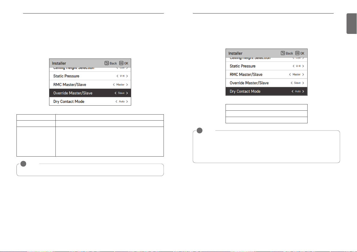
INSTALLER SETTING
126
Override Master/Slave setting (air conditioner / General, DX
ventilator)
The operation master / slave selection function is to avoid other mode operations, and it is the
function to prevent the selection of opposite mode of the indoor unit master by the indoor units
set as slaves.
• Change setting values using [<,>(left/right)] button.
M/S Description
Master Using group control, this master sets the mode of slave IDU’s.
For the indoor unit set as slave, it can only select the some operation
mode of the master indoor unit cycle.
Slave
NOTE
!
Override M/S setting function is only available in some products.
Ex) Master is in cooling cycle, Slave can select cooling, dehumidification, auto, and wind only
Master is in heating cycle, Slave can select auto, heating, and wind
only
INSTALLER SETTING
Dry contact mode setting (air conditioner / DX ventilator)
Dry contact function is the function that can be used only when the dry contact devices is separately purchased and installed.
• Change setting values using [<,>(left/right)] button.
Value
Auto
manual
NOTE
!
For dry contact mode related detail functions, refer to the individual dry contact manual.
What is dry contact?
It means the contact point signal input when the hotel card key, human body detection
sensor, etc. are interfacing with the air conditioner.
Added system functionality by using external inputs (dry contacts and wet contacts).
127
ENGLISH

INSTALLER SETTING
128
Fixed air volume (air conditioner / DX ventilator)
It is the function to apply different fan speeds automatically for each thermal control status.
• You can set the following setting values using [<,>(left/right)] button.
INSTALLER SETTING
Zone Type Setting(air conditioner)
This function is only available on some products.
This function select a type of zone control type which indoor unit support as 'new type' or 'old
type'.
129
ENGLISH
Value Comp on Comp off
Variable Set fan speed Low
Fixed Set fan speed Set fan speed
Value
Old
New(4 Zone)
New(8 Zone)
Zone Number Setting(air conditioner)
This function is only available on some products.
Zone Number is to set the number of installed zones. It's possible to control only in zone new
type.
Value
New(4 zone) : 2~4
New(8 zone) : 2~8

INSTALLER SETTING
130
Emergency heater setting (air conditioner)
Enable the emergency heater control function and the usage environment.
• In the installer setting list, select the emergency heater setting category, and press [OK] button
to move to the detail screen.
- In case of an error, it sets whether the emergency heater can be used / outdoor temperature
standard heater operation usage setting and temperature step value setting / and during the
emergency heater operation, whether to use the indoor unit fan operation.
OK
INSTALLER SETTING
Function control during group Control setting (air conditioner)
This function enables the control of the common functions or some functions based on the master indoor unit during the group control.
• Change setting values using [<,>(left/right)] button.
Value Description
Not use Common function,
Use
NOTE
!
Common functions and some indoor unit master standard setting shall be set only during
the group control with the same type indoor units.
During the group control with different indoor unit types, set it as ‘000’ to use the existing
group control method.
Use expanded function which
is based on master indoor unit
131
ENGLISH
Outdoor temperature standard heater
Value
Not use - -
Emergency heater Step 0 ~ 3
Use
Extended emer-
gency heater
NOTE
!
This function setting must be carried out by a certified-technician.
operation
Step 0 ~ 15
Fan operation in emergency
control
On/Off

INSTALLER SETTING
132
External devices of indoor unit setting (air conditioner)
At the Code field, select when air cleaner/heater/humidifier/elevation grill/ventilation KIT/Aux
Heater/refrigerant leakage detection sensor are newly installed to the indoor unit or when an installed KIT is removed.
• You can set the following setting values using [<,>(left/right)] button.
Function Value
Plasma purification
Heater
Humidifier
Elevation grill
Ventilation Kit
Aux Heater
Refrigerant leakage detection sensor
Not install / Install
INSTALLER SETTING
Expand of Temperature Range (air conditioner)
This function using in dual setpoint control mode.
This function is used for select setting temperature range option.
Value
Clear : 60~86 °F / 16~30 °C (default)
Set : 40~99 °F / 4~37.5 °C
NOTE
!
When the set values are changed, the items below will be initialized.
- Target temperature (default: Cooling: 86 °F(30 °C)/ Heating: 60 °F(16 °C))
'home leave' temperature (default: Cooling: 86 °F(30 °C)/ Heating: 60 °F(16 °C))
In case of the setting expanded temperature range (set), please note that the setting of the
wired remote controller can be altered under below circumstances.
- In case of cooling at 30~37.5 °C(64~99 °F), it is changed to cooling at 86 °F(30 °C).
- In case of heating at 4~15.5 °C(40~86 °F), it is changed to heating at 60 °F(16 °C).
- If set on dual setpoint, it is changed to the current operation mode(cooling or heating) of
the indoor unit.
Situation where changes in the setting occur
a. Operates the Auto address work and pipe search in situations such as product installment
and service.
b. Occurrence of errors and deactivation.
c. Command generated by the central control, outdoor unit, Dry contact, Remote controller,
indoor unit switch.
133
ENGLISH

INSTALLER SETTING
134
Indoor unit address verification (air conditioner / DX ventilator)
This function allows you to check the address of the indoor unit designated by the outdoor unit.
• In the installer setting list, select the indoor unit address check category, and press [OK] button
to move to the detail screen.
INSTALLER SETTING
Static pressure step setting (air conditioner)
It is the function to subdivide and set the product’s Static pressure to 11 stages.
• Change setting values using [<,>(left/right)] button.
135
ENGLISH
OK
Value
Step 0 ~ Step 11
NOTE
!
If Static pressure step setting is used, the Static pressure setting is not used.
For the Static pressure step value for each stage, refer to the indoor unit product manual

INSTALLER SETTING
136
Guard timer(air conditioner)
It is a function that sets the minimum running time of outdoor unit cycle mode when switching
from cooling mode to heating mode and vice versa during Auto Operation mode.
Under the condition of cooling/heating switching, it switches between cooling and heating mode
after operation during the time scheduled in the Guard timer.
Step Value
0 0 minute
1 15 minutes
2 30 minutes
3 45 minutes
4 60 minutes
INSTALLER SETTING
Fan speed in Cooling thermal off (air conditioner)
Indoor unit fan, in cooling mode, during thermal off condition.
• Select value using [<,>(left/right)] button.
Value
Low Fan speed low
Off Fan off
Setting fan speed setting value
137
ENGLISH

INSTALLER SETTING
138
Primary heater setting(air conditioner)
It is the function to set the air conditioner fan operation if the ventilation is operated while the air
conditioner operation is stopped when the air conditioner and the ventilation are installed to interface with each other.
• You can set the following setting values using [<,>(left/right)] button.
Value Description
Not use During the heating, heater is set to be used as secondary
Use During the heating, heater is set to be used as main
INSTALLER SETTING
139
Air conditioner Fan operation interlocked with ventilation setting
(air conditioner)
It is the function to set the air conditioner fan operation if the ventilation is operated while the air
conditioner operation is stopped when the air conditioner and the ventilation are installed to interface with each other.
• You can set the following setting values using [<,>(left/right)] button.
Value Description
Off The air conditioner indoor unit Fan is Off during the ventilation interface
The air conditioner indoor unit operates in very weak wind during the ventila-
On
tion interface
- When the air conditioner operation is Off, if the ventilation product is in operation, the air conditioner fan shall be operated, and when the fan is in operation, dust may fall, so it is the function
to set the air conditioner fan operation status in case of ventilation interface through the setting.
ENGLISH

INSTALLER SETTING
140
Indoor unit Auto-Start setting (air conditioner / DX ventilator)
It is a function that sets whether to restore the indoor unit operation by resuming the previous
power-on state or as power-off state in the power failure compensation.
• You can set the following setting values using [<,>(left/right)] button.
INSTALLER SETTING
Occupancy duration time setting(air conditioner)
It is a function that sets the light-on/occupancy duration after motion is detected when installing
an occupancy sensor.
• You can set the following setting values using [<,>(left/right)] button.
141
ENGLISH
Value Description
Use Use indoor unit auto restart
Not use Not use indoor unit auto restart
Value
0 Minute
10 Minutes
30 Minutes
60 Minutes

INSTALLER SETTING
142
CN_CC setting (air conditioner)
It is the function to set the usage of the indoor unit’s CN_CC port.
• Select CN_CC setting category, and press [OK] button to move to the detail screen.
OK
INSTALLER SETTING
CN_EXT setting (air conditioner / DX ventilator)
It is the function to set to control the external input and output according to DI/DO set by the
customer using the indoor unit’s Dry Contact Port. (It is the function to decide the usage of the
contact point port (CN_EXT) mounted in the indoor unit PCB.)
• In the installer setting list, select CN_EXT setting category, and press [OK] button to move to
the detail screen.
OK
143
ENGLISH
Value Description
DC auto install
(default)
DC manual not install Do not use (install) Dry Contact
DC manual install Use (install) Dry Contact
Programmable DI/DO Use as Programmable DI/DO (Simple On/Off)
NOTE
!
CN_CC is the device connected to the indoor unit to recognize and control the external
contact point.
When power is applied to the product, indoor unit when the contact
point is on in Dry Contact installed state recognizes Dry Contact installation
Value Description
Not use (default)
Simple operation
control
Single emergency stop Indoor unit single emergency stop
Occupied / Unoccupied Occupied / Unoccupied
All emergency stop
Window contact
Window contact lock
Use installer code No. 41 setting value (simple Dry Contact setting value)
Simple operation On/Off
Indoor unit all emergency stop
※
It can be set only when there is indoor unit emergency stop function.
Window contact
※ It can be set only when there is window contact function.
Window contact with lock
※ It can be set only when there is window contact lock function.

INSTALLER SETTING
144
Outdoor unit function master setting (air conditioner / DX ventilator)
It is the function to set the outdoor unit’s function Master / Slave.
• You can set the following setting values using [<,>(left/right)] button.
INSTALLER SETTING
Fan continuous operation setting (air conditioner)
It is the function to set the indoor unit’s continued fan function usage. (It is the function to maximize the cooling/heating efficiency by the outdoor unit operating the indoor unit fan operation
longer than the previous operation method.)
• You can set the following setting values using [<,>(left/right)] button.
145
ENGLISH
Value Description
Cannot enter the Smart load control function setting
Slave
Master
CAUTION
!
※When you change the outdoor unit function master setting from master to slave, check the op-
eration status of the outdoor unit function (outdoor unit low noise operation, smart load control)
and make sure to stop the outdoor unit function before the change.
Cannot enter the low noise operation time setting
Cannot enter the refrigerant noise reduction setting
Cannot enter the defrost mode setting
Smart load control function setting is possible
Low noise operation time setting is possible
Refrigerant noise reduction setting is possible
Low noise operation control main agent setting is possible
Defrost mode setting is possible
Value Description
Clear Do not use continued fan usage
Set Use continued fan usage
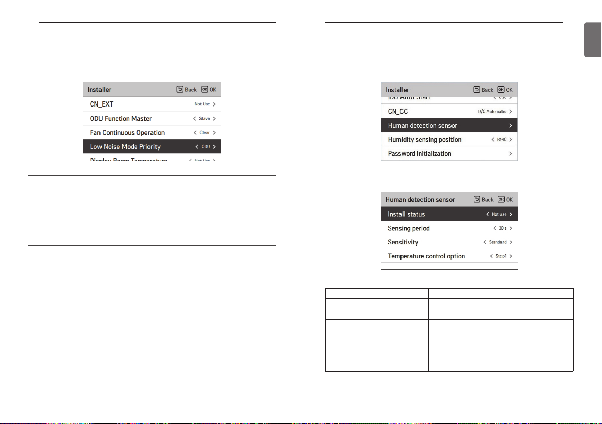
INSTALLER SETTING
146
Low Noise Mode Priority setting (air conditioner / DX ventilator)
It is the function to set the low noise mode control main agent. (It is the function to set that only
one of the outdoor unit / remote controller can control the low noise operation.)
• You can set the following setting values using [<,>(left/right)] button.
INSTALLER SETTING
Human detection sensor (air conditioner)
It is the function to set whether to install human detection sensor and operation standard value.
• In the installer setting list, after selecting human detection sensor setting category, if you press
[OK] button, it moves to the detail screen.
147
ENGLISH
Value Description
RMC
ODU(default)
Ignore the outdoor unit PCB’s low noise operation Switch Setting value
- Function setting – remote controller low noise operation time menu deactivation
It is controlled in the outdoor unit itself according to the outdoor unit
PCB’s low noise operation Switch Setting value
- Function setting – remote controller low noise operation time menu deactivation
• You can set the following setting values for each category using [<,> (left/right)] button.
Value Description
Installation status Not installed, basic installation, 90º rotation installation
Detection result sending cycle 5 s, 30 s, 1 min., 3 min.
Sensitivity setting Standard, low sensitivity, high sensitivity
Step 0 : Keeps the product running and uses the tem-
Temperature control option
Detection Area Setting Indoor floor area detection, 6X6, 12X6
perature power saving function.
Step 1 : The operation of indoor units is stopped by
using the temperature power saving function.

INSTALLER SETTING
148
Humidity sensing position (air conditioner)
It is the function to set the location to detect humidity.
You can use [<, > (left/right)] button to set the following setting values.
INSTALLER SETTING
ODU cycle priority (air conditioner)
This function can set cycle priority of outdoor unit.
Multi V Heat Pump system does not support mixed mode therefore wired remote controller can
not show opposite operation mode for select option while ODU operate cooling or heating cycle.
Set this function user can select opposite operation mode with wired remote controller and in-
door units enter to ‘standby’ status or outdoor unit can support cooling first and operate heating
with heater.
149
ENGLISH
Remote controller (default value) Humidity sensor of the remote controller itself
Value Description
Indoor unit Humidity received from indoor unit
OK
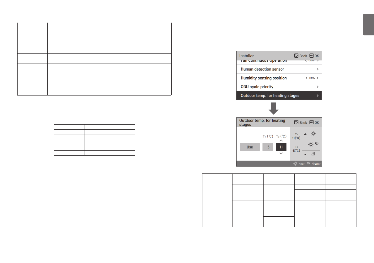
INSTALLER SETTING
150
Option Description
Not use
Standby
Cool
h When user select cooling option, additional setting menu will be activated.
The additional timer setting menu is for setting minimum cooling operation period.
Once outdoor unit change over to cooling by cooling priority, outdoor unit can change over to
heating after set time.
Does not support opposite cycle operation using wired remote controller
- When ODU operate as cooling cycle selectable operation modes with
wired remote controller are cool, auto, dehumidification and fan.
- When ODU operate as heating cycle selectable operation modes with
wired remote controller are heat, auto and fan
When user set opposite operation mode using wired remote controller indoor unit stop thermal operation and fan.
Cooling cycle has a priority.
When user change operation mode of specific indoor unit to cooling on
heating cycle, outdoor unit change cycle to cooling and Indoor unit keep
heating operation using heater.
h Please set emergency heater and aux heater function before using this
option
Setting value Cooling operation time
Step 0 45 min.(default)
Step 1 30 min.
Step 2 60 min.
Step 3 90 min.
Step 4 120 min.
INSTALLER SETTING
Outdoor temp. for heating stages (air conditioner)
It is a function that sets outdoor temperature values for two stage heating.
if user set outdoor temperature T1 and T2, Indoor unit will select heating stage between Indoor
unit operation and heater operation.
OK
151
ENGLISH
SW Version Setting value Option T1 value T2 value
~2.08.2a
2.09.0a~
※ Even if the remote control version is 2.09.0a or more, Features may not be supported.
Not Use - - -
Use -
Not Use - - -
Auto -
Heat pump
Manual
Heater + H/P
-23 ~ 16 °C -23 ~ 51 °C
(-10 ~ 60 °F) (-10 ~ 130 °F)
-23 ~ 16 °C -23 ~ 51 °C
(-10 ~ 60 °F) (-10 ~ 130 °F)
- -Heater

INSTALLER SETTING
152
Estimated energy display (air conditioner)
This function can set to display energy data which outdoor unit estimated power consumption
data without wattmeter.
Setting value Description
Use Display energy consumption data which outdoor unit estimated
Not Use Not display energy consumption data which outdoor unit estimated
CN_PTC setting (air conditioner)
This is a function to set PTC Port of indoor unit.
INSTALLER SETTING
Password initialization (air conditioner / general, DX ventilator)
It is the function to initialize (0000) when you forgot the password set in the remote controller.
• In the installer setting list, select the password initialization setting category, and press [OK]
button to move to the detail screen.
• When you press “initialization” button, a popup screen appears, and when you press “check”
button, password initialization starts, and the user password is changed to 0000.
OK
153
ENGLISH
Setting value Description
Normal Auxiliary heating interlock deactivated
Special Auxiliary heating interlock activated

INSTALLER SETTING
154
Auto ESP (air conditioner)
This function automatically sets the rotation speed of the fans corresponding to each step of
rated airflow for easy installation.
• Select Auto ESP and press the [OK] button to move to the detail screen.
OK
After selecting the voltage setting, the product will automatically operate and automatically set
the rotation speed for each fan speed - High, Medium, and Low.
Check the product type and select “Auto” for a Single product and “Manual” for a Multi V product.
Value Description
Off Not in use
Auto Automatically selects the voltage
Manual
Selects the voltage (190V-270V)
* Only for Multi V products
INSTALLER SETTING
While setting, a pop-up is displayed. This means that Auto ESP is being set.
(It takes approximately 3 to 8 minutes.)
Product operation is terminated once the rotation speed setting is complete.
You can check the results as Pass or Fail.
If it fails, you cannot use the Auto ESP function.
Instead of Auto ESP, the conventional ESP setting method can be used.
NOTE
!
If Auto ESP is incorrectly set, the air conditioner may malfunction.
This function must be set by an installation specialist with an installation license.
155
ENGLISH

INSTALLER SETTING
156
Dust step color setting
This function is to set the dust step color.
• In the install setting list, select the dust step color setting category and press [OK] to open the
details window.
Value Step
Type 1 4Step(for Korea)
Type 2 4Step(for Global)
Type 3 6Step(for China)
* The dust step color may not be displayed in some products.
Product direction (general ventilator)
It is the function to set the direction of the ventilation product.
• Select value using [<,>(left/right)] button.
INSTALLER SETTING
Express ventilation priority (general , DX ventilator)
It is the function to set the priority of the air supply and air discharge during the express ventilation operation.
• Select value using [<,>(left/right)] button.
Value
Priority in air supply Priority in air discharge
157
ENGLISH
Value
Normal Reverse

INSTALLER SETTING
158
Humidification of stand-alone ventilation mode (general , DX
ventilator)
It is the function to set whether to use the humidification function during the ventilation product
single operation.
• Select value using [<,>(left/right)] button.
INSTALLER SETTING
Humidification of ventilation with heating operation
(DX ventilator)
It is the function to set the heating humidification function of the direct ventilation to be automatic or manual.
• Select value using [<,>(left/right)] button.
159
ENGLISH
Value
Not use Use
Value
Not use Use

INSTALLER SETTING
160
Ventilation Fan Speed Alignment (general ventilator)
It is the function to change the standard fan speed of the ventilation product.
• Select value using [<,>(left/right)] button.
GUIDE TO DIFFERENT MODE OPERATION/OPEN SOURCE SOFTWARE
GUIDE TO DIFFERENT MODE
OPERATION/OPEN SOURCE SOFTWARE
Different mode operation
Different mode operation is the case when the indoor units’ operation modes are different when
multiple indoor units are installed to one outdoor unit. (Different mode operation doesn’t happen
in the cooling exclusive model.)
• Example of different mode operation
- When one indoor unit is operated in heat while several indoor units one outdoor unit are operated in cooling, the heating operation is not performed.
- With one outdoor unit, while several indoor units are in heat mode, if one indoor unit requests
in cooling or dehumidification, the operation is not performed.
161
ENGLISH
Value
Default value 10% increase 10% decrease 20% decrease
Filter check alarm(general ventilator)
This function sets the filter check alarm of the ventilation product.
• Select value using [<,>(left/right)] button.
Value
Step 0 - 5
Open Source Software Notice Information
To obtain the source code under GPL, LGPL, MPL, and other open source licenses, that is contained in this product, please visit http://opensource.lge.com. In addition to the source code, all
referred license terms, warranty disclaimers and copyright notices are available for download. LG
Electronics will also provide open source code to you on CD-ROM for a charge covering the cost
of performing such distribution (such as the cost of media, shipping, and handling) upon email request to opensource@lge.com. This offer is valid for a period of three years after our last shipment of this product. This offer is valid to anyone in receipt of this information.

 Loading...