

LG PQRCUSA0 Owner’s Manual

ENGLISH ITALIANO ESPAÑOL FRANÇAIS DEUTSCH
LG
LG
Wide Wired Remote Controller
Owner's & Installation Manual
Models:PQRCUSA0
IMPORTANT
• Please read this owner's & installation manual completely
before installing the product.
• Installation work must be performed in accordance with
the national wiring standards by authorized personnel
only.
• Please retain this owner's & installation manual for future
reference after reading it thoroughly.
Safety Precaution
Owner’s & Installation Manual 3
ENGLISH
2 Wide Wired Remote Controller
Wide Wired Remote Controller Owner’s & Installation Manual
TABLE OF CONTENTS
■ Safety Precaution .............................................................................................3~4
■ Part Description ....................................................................................................5
■ Installation instruction .........................................................................................6
Group control ........................................................................................................8
Installer Setting-How to enter installer setting mode.............................................9
Installer Setting-Test Run mode .........................................................................11
Installer Setting-Setting Address of Central Control............................................12
Installer Setting-E.S.P. ........................................................................................13
Installer Setting-Thermistor .................................................................................15
Installer Setting-Ceiling Height Selection ............................................................16
Installer Setting-Static Pressure Setting..............................................................17
Installer Setting-Group Setting ............................................................................18
Installer Setting-Mode Override Setting ..............................................................19
Installer Setting-Dry Contact Mode Setting .........................................................20
Installer Setting-Airflow Rate Setting...................................................................21
Installer Setting-Celsius/Fahrenheit Switching....................................................22
Installer Setting-Zone Type Setting.....................................................................23
Installer Setting-Zone Number Setting ................................................................24
Installer Setting-Option Function Setting.............................................................25
■ Owner's instruction ............................................................................................26
Cooling Mode-Standard Operation .....................................................................26
Cooling Mode-Powr Cooling ...............................................................................27
Dehumidification Mode........................................................................................28
Auto Changeover Mode ......................................................................................28
Auto Operation Mode ..........................................................................................29
Fan Mode ............................................................................................................30
Temperature Setting/Room Temperature Check ................................................31
Airflow Setting .....................................................................................................32
Sub function: Plasma Purification .......................................................................33
Sub function: Humidifier ......................................................................................33
Sub function: Electric Heater...............................................................................34
Sub function: Fan Auto........................................................................................35
Function setting: Filter Sign Clear .......................................................................35
Function setting: Child Lock ................................................................................36
Function setting: Elevation Grill...........................................................................37
Function setting: Vane Angle Control..................................................................38
Function setting: Mode Change Temp ................................................................39
Function setting: Zone Control ............................................................................40
Changing Current Time.......................................................................................41
Programming: Setting Simple Reservation .........................................................43
Programming: Setting Sleep Reservation ...........................................................44
Programming: Setting ON Reservation...............................................................45
Programming: Setting OFF Reservation .............................................................46
Programming: Weekly Reservation.....................................................................47
Programming: Holiday Reservation ....................................................................49
Ventilation Kit Control..........................................................................................50
Error code display function..................................................................................51
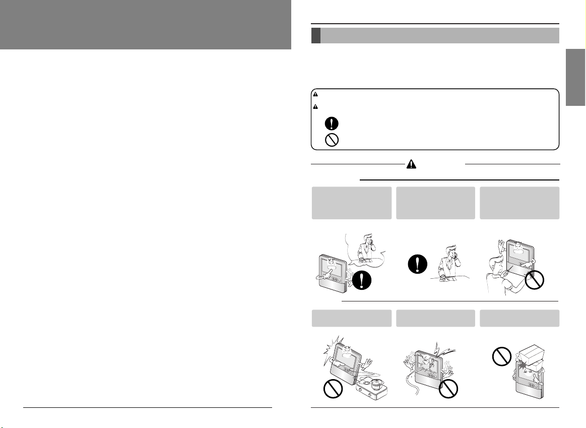
Be sure to request to the
service center or installation
specialty store when
installing products.
• It will cause fire or electric shock
or explosion or injury.
Request to the service center
or installation specialty store
when reinstalling the
installed product.
• It will cause fire or electric shock
or explosion or injury.
Do not disassemble, fix, and
modify products randomly.
• It will cause fire or electric shock.
Do not place flammable
stuffs close to the product.
• It will cause fire.
Do not allow water to run
into the product.
• It will cause electric shock or
breakdown.
Do not give the shock to the
product.
• It will cause breakdown when
giving the shock to the product.
■ Installation
Safety Precaution
• The installation requires expert skills, and it should be installed by the service center or other shops specialized
in the installation and recognized by our company.
• For all the problems arising after installation by someone who has no relevant qualifications, our company will
not provide free service.
• The following safety cautions are provided to prevent unexpected dangers or losses.
: If the user does not follow the mandatory items, it may result in serious injury or death.
: If the user does not follow the mandatory items, it may cause personal injury or property
damage.
: Warning and Caution are to call the user’s attention to the possible danger. Read and follow
them carefully in order to prevent a safety accident.
: Warning and Caution are indicated in this guide and the product itself to help protect the users
from danger.
WARNING
CAUTION
WARNING
■ In-use
TEMP
TEM
P
T
E
M
P
TEMP
TEMP
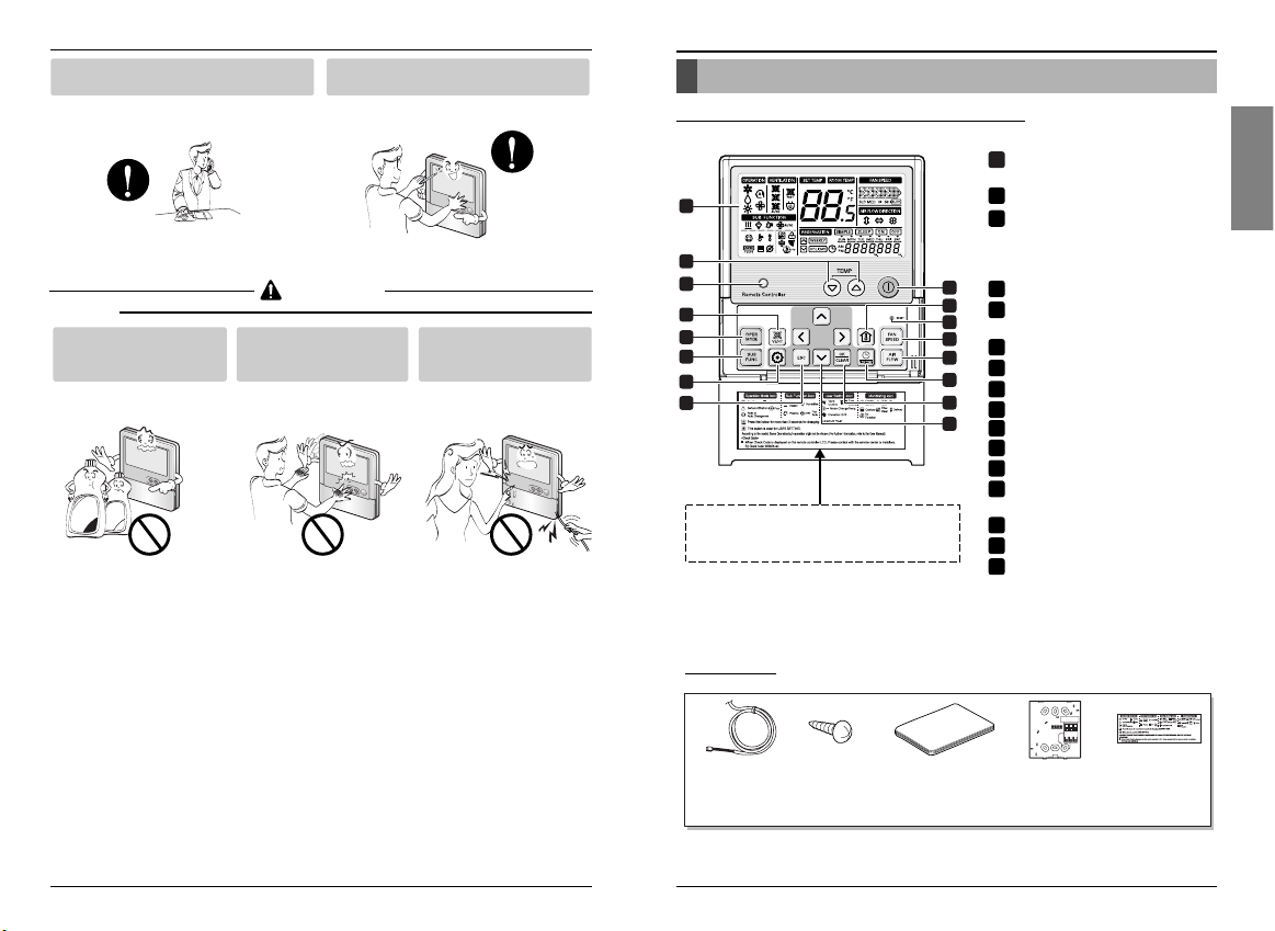
Part Description
Owner’s & Installation Manual 5
ENGLISH
Part Description
Name and Function of Remote Controller
Safety Precaution
4 Wide Wired Remote Controller
■ In-use
CAUTION
OPERATION INDICATION
SCREEN
SET TEMPERATURE Button
WIRELESS REMOTE
CONTROLLER RECEIVER
• Some products don't receive the
wireless signals.
VENTILATION Button
OPERATION MODE SELECTION
Button
SUBFUNCTION Button
FUNCTION SETTING Button
EXIT Button
ON/ OFF Button
ROOM TEMPERATURE Button
FAN SPEED Button
AIR FLOW Button
RESERVATION/ TIME SETTING
Button
SETTING/ CANCEL Button
UP, DOWN, LEFT, RIGHT Button
RESET Button
Request to the service center or installation
specialty store when the product becomes wet.
• It will cause fire or electric shock.
Do not give the shock using sharp and
pointed objects.
• It will cause breakdown by damaging parts.
Do not clean using the
powerful detergent like
solvent but use soft cloths.
• It will cause fire or product
deformation.
Do not press the screen
using powerful pressure or
select two buttons.
• It will cause product breakdown or
malfunction.
Do not touch or pull the lead
wire with wet hands.
• It will cause product breakdown or
electric shock.
TEMP
12VSIG GND
1
9
11
16
12
3
5
6
2
4
10
13
14
7
8
15
Please attach the inform label inside of the door.
Please choose proper language defend on your
country.
1
2
3
4
5
6
7
8
9
10
11
12
13
14
15
16
Connection Cable
(1EA, 10m)
Remote controller
screw
(4 EA)
Owner's /
Installation manual
Wired remote
controller
installation board
Inform label
(5EA-5Language)
Accessory
❊ Some functions may not be operated and displayed depending on the product type.
Wax
TEMP
Thinner
TEMP
TEMP
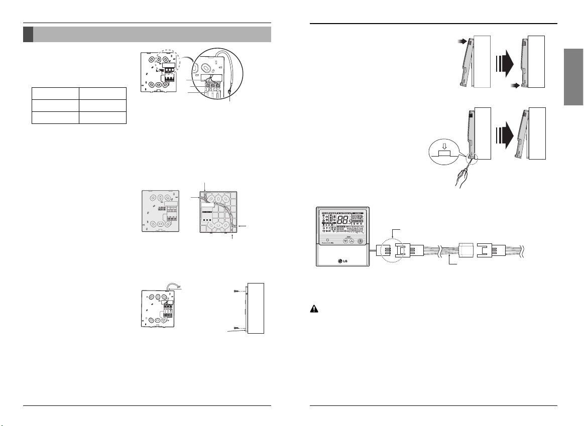
Installation instruction
Owner’s & Installation Manual 7
ENGLISH
Installation instruction
6 Wide Wired Remote Controller
12V SIG GND
Red
Yellow
Black
Remote Controller
Cable
Guide slot
Fixate the remote
controller cable
to the guide slot.
Use the screws
for fixate the unit
firmly on the wall.
Installation board
<Front side of
installation board>
<Rear side of
installation board>
Top
Bottom
Wall
Side
Wall
Side
Wall
Side
Wall
Side
Wall
Side
Check whether the connector
is connected correctly.
Connecting cable
Indoor
unit side
1. Connect the remote controller
cable to the wired remote
controller installation board as
shown in the right picture.
2. After fixing the cable to the guide
slot, attach the wired remote
controller installation board at the
desired location.
• Before fixing the remote controller cable to the
guide slot, remove any clogged part of the
case in the direction to install before the
installation.
3. After locating the wired remote
controller installation board at the
desired location, screw the unit
firmly. (When there is a buried
box, install the wired remote
controller board to fit the buried
box.)
• Use the screws provided.
4. After fixing the top part of the
remote controller to the installation
board as shown in beside picture,
press the bottom part to assemble
the controller to it’s board.
When disassembling the remote
controller from the installation board, use
the driver as shown in the right picture
and insert it into the hole with the arrow.
And when you pull the driver in the front
direction, the remote controller will be
separated.
Installation instruction
12V Red wire
SIG Yellow wire
GND Black wire
5. Use the connecting cable to connect the indoor unit and the remote controller.
6. When the distance between the wired remote controller and the indoor unit is 10m
and above, use the extension cable.
When installing the wired remote controller, do not bury it in the wall.
(It can cause damage in the temperature sensor.)
Do not install the cable to be 50m or above.
(It can cause communication error.)
• When installing the extension cable, check the connecting direction of the connector of the remote controller
side and the product side for correct installation.
• If you install the extension cable in the opposite direction, the connector will not be connected.
• Specification of extension cable: 2547 1007 22# 2 core 3 shield 5 or above.
CAUTION
❊ The remote controller cable is connected as factory default.
Owner’s & Installation Manual 9
ENGLISH
Installation instruction
Installer setting mode is to set the detail function of the remote controller.
If the installer setting mode is not set correctly, it can cause problems to the product, user injury or
property damage. This must be set by an certificated installer, and any installation or change that is
carried out by a non-certificated person should be responsible for the results. In this case, free service
cannot be provided.
Installation instruction
8 Wide Wired Remote Controller
GND
GND
12V
Signal wire
Signal wire
GND
12V
B Y R B Y R
MASTER SLAVE
Signal wire
GND
12V
Signal wire
CAUTION
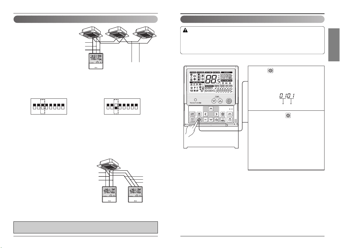
Group control Installer Setting -How to enter installer setting mode
1. When installing more than 2
units of air conditioner to one
wired remote controller, please
connect as the right figure.
• If it is not event communication
indoor unit, set the unit as slave.
• Check for event communication
through the product manual.
• Refer to regarding page on how to
set the slave.
When controlling multiple indoor units with event communication function with one remote
controller, you must change the master/slave setting from the indoor unit.
- For ceiling type cassette and duct product group, change the switch setting of the indoor PCB.
For wall-mount type and stand type product, change the master/slave setting with the wireless
remote controller. (Refer to wireless remote controller manual for detail)
❈ When installing 2 remote controllers to one indoor unit with event communication function, set
the master/slave of the remote controller. (Refer to remote controller master/slave selection)
When controlling the group, some functions excluding basic operation setting, fan level
Min/Mid/Max, remote controller lock setting and time setting may be limited.
#3 switch OFF: Master (Factory default setting) #3 switch ON: Slave
2.
When installing more than 2 wired
remote controllers to one air conditioner,
please connect as the right picture.
•
When installing more than 2 units of wired
remote controller to one air conditioner, set one
wired remote controller as master and the others
all as slaves, as shown in the right picture.
• Refer to Installer setting section on how to
set master/slave.
• You cannot control the group as shown in
the right for some products.
<When simultaneously connecting
2 sets of wired remote controller>
❊
Some products do not use 'Group control'. It depends on the product type.
For more detail, refer to the product manual.
❊ Some contents may not be displayed depending on the product function.
1ON2345678
1ON2345678
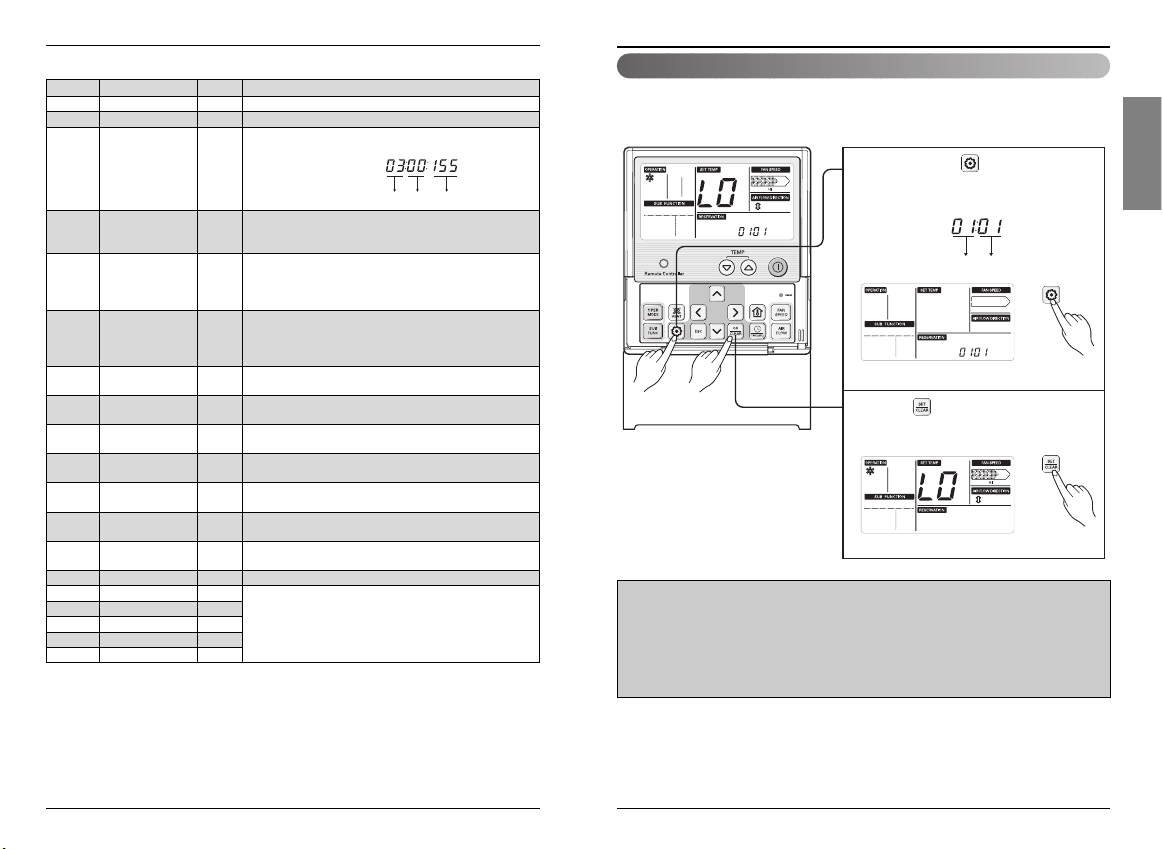
Press button for 4 secsonds to enter
1
the installer setting mode. (When you
enter the setting mode initially, Function
code is displayed on the bottom of the
LCD screen.)
Function Code Value
Repeat pressing button, the menu
2
will change with the corresponding
function code.
1
* Please refer to the following page for
the function lists.
Installation instruction
Owner’s & Installation Manual 11
ENGLISH
Installation instruction
10 Wide Wired Remote Controller
<Installer Setting Code Table>
Installer Setting -Test Run Mode
After installing the product, you must run a Test Run mode.
For details related to this operation, refer to the product manual.
❊ 18˚C cooling, High Fan Speed, Airflow direction mode will be operated during 18 minutes with
ignoring room temperature.
❊ After running 18 minutes under test run mode, system will automatically turn OFF.
❊ In case of duct type, the Airflow UP/DOWN function is not displayed.
❊ During test run mode, receiving signal from wireless remote controller will release this operation.
If you press any kind of button, Test Run mode will be released.
❊ Some contents may not be displayed depending on the product function
No. Function Code Value
1 Test Run 01 01:Set
2 Address Setting 02 00~FF : Address
<ESP Step> <ESP Value>
01:VeryLow 0 ~ 255
02:Low
3 E.S.P. Value 03
03:Med
04:High
05:Very High
01:Remo
4 Thermistor 04 02:Indoor
03:2TH
01:Med
02:Low
5 Ceiling Height 05
03:High
04:Very High
01:V-H
02:F-H
6 Static Pressure 06
03:V-L
04:F-L
7 Group Setting 07
00:Slave
01:Master
8 Override Setting 08
00:Slave
01:Master
9 Dry Contact 09
00:OFF
01:ON
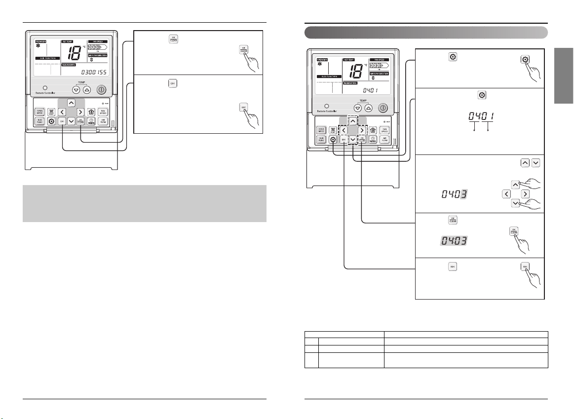
10
Release 3 Min.
10 01:Set
Delay
11 Zone State 11
01:Variable
02:Fixed
12
Celsius
12
00:Celsius
(Optimized only for U.S.A)
Fahrenheit Switching 01: Fahrenheit
13 Zone Type 13
00:Old
01:New
14 Zone Number 14 02~04(Zone number)
15 Plasma 20
16 Electric heater 21
17 Humidifier 22
00: Not Installed
18 Elevation Grill 23
01: Installed
19 Ventilation Kit 24
Function Code ESP valueESP step
Keep pressing button setting for 4
1
secs to enter installer setting mode until
code displayed in timer segment.
Function Code Set
1
2
Press button to start.
2
Owner’s & Installation Manual 13
ENGLISH
Installation instruction
Installation instruction
12 Wide Wired Remote Controller
Installer Setting - Setting Address of Central Control
Installer Setting -E.S.P.
If you set ESP incorrectly, the air conditioner may malfunction.
This setting must be carried out by a certificated-technician.
This function is used for only Duct product.
CAUTION
What is an E.S.P function?
This is the function that decides the strength of the wind for each wind level and because this
function is to make the installation easier, please do not use this function when using the remote
controller.
Press the button for 4
1
seconds to enter the installer
setting mode until timer segment
display "01:01".
Repeat pressing button to select
2
Function code 02.
Function Code Group No
Ex) Setting Address as 'F5'
Set Group No. by pressing
3
button.
Indoor No.
Press button for 4 seconds
1
to enter the installer setting
mode until timer segment
display “01:01”.
Repeat pressing button to select
2
Function code 03.
Move to Indoor No. setting option
4
by pressing button.
Set Indoor No. by pressing
5
button.
Press button to save or release.
6
Press button to exit or system will
7
automatically exit after 25 seconds
without any input.
Function Code ESP valueESP step
Set ESP step by pressing button.
3
(01: very low, 02: low, 03: medium, 04:
high. 05: power)
Move to ESP setting by pressing
4
button.
Press button to select ESP
5
value(0~255).
Owner’s & Installation Manual 15
ENGLISH
Installation instruction
Installation instruction
14 Wide Wired Remote Controller
Installer Setting -Thermistor
❊ Therefore system will use value that sensed from indoor unit or remote controller
❊ Weak and Power setting is not available for some products.
❊ Because the ESP value is already appropriately set when manufactured from the factory, it is
recommended that you do not change the ESP value.
<Thermistor Table>
Temperature sensor location Function
01 Remote controller Operation in remote controller Temperature sensor
02 Indoor unit Operation in indoor unit temperature sensor
03 2-Thermistor(2TH)
Operation in lower temperature after comparing the temperature between
the indoor unit and remote controller
Press button to save or release.
6
Press button to exit or the system
7
will automatically exit after 25 seconds
without any input.
1
2
3
4
5
Press button for 4 seconds
to enter the installer setting
mode until timer segment
display “01:01”.
Repeat pressing button to select
Function code 04.
Function Code Thermistor setting
Ex) Setting Thermistor as '2TH'.
Set Thermistor mode by pressing
button. (01: Remote Controller,
02: Indoor, 03: 2TH)
Press button to save or release.
Press button to exit or
system will automatically exit
after 25 seconds without any
input.
Owner’s & Installation Manual 17
ENGLISH
16 Wide Wired Remote Controller
Installation instruction
Installation instruction
Installer Setting -Ceiling Height Selection Installer Setting -Static Pressure Setting
This function is to adjust FAN Airflow rate according to ceilingheight (only cassette model)
This function is applied to only duct type. Setting this in other cases will cause malfunction.
❊ Ceiling height setting is available only for some products.
❊ Ceiling height of ‘Super high’ function may not exist depending on the indoor unit.
❊ Refer to the product manual for more details.
Pressure selection
Function
Zone state ESP standard value
01 V-H Variable High
02 F-H Fixed High
03 V-L Variable Low
04 F-L Fixed Low
Ceiling Height Level Description
01 Low Decrease the indoor airflow rate 1 step from standard level
02 Standard Set the indoor airflow rate as standard level
03 High Increase indoor airflow rate 1 step from standard level
04 Super high Increase indoor airflow rate 2 steps from standard level
<Ceiling Height Selection Table>
<Static Pressure Setting Table>
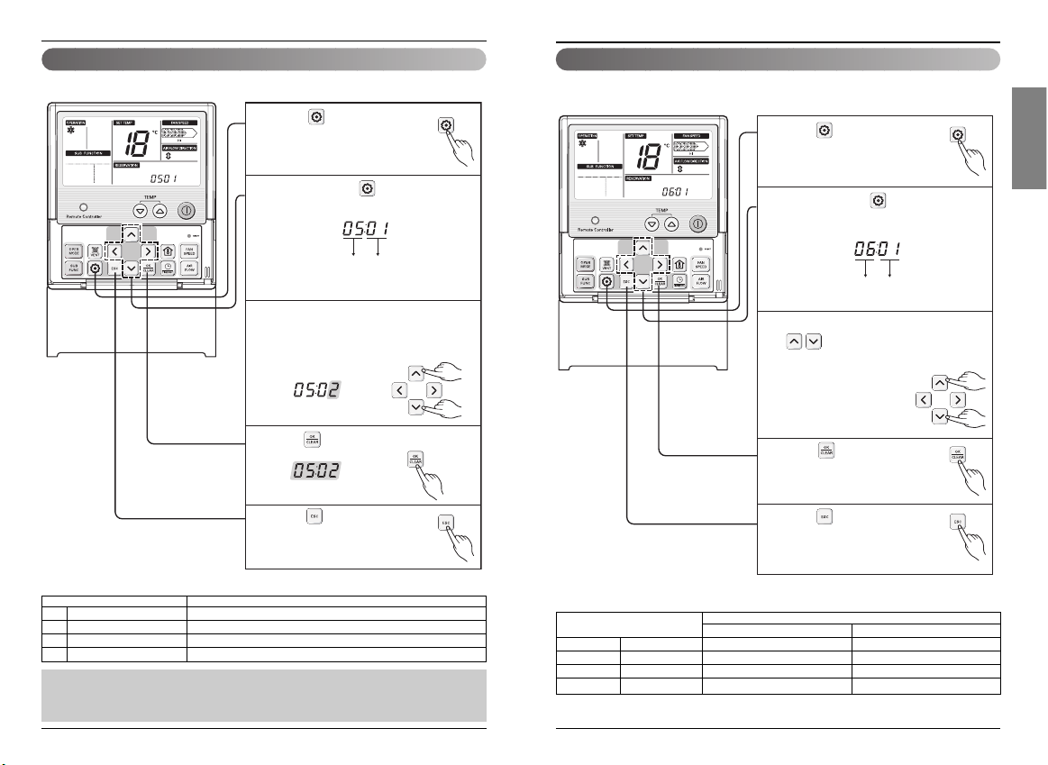
Press button for 4 seconds
1
to enter the installer setting
mode until timer segment
display “01:01”.
Repeat pressing button to select
2
Function code 05.
Function Code Ceiling height
Ex) Setting Ceiling Height as 'Standard'.
Select ceiling height value by pressing
3
button.
(01:Low, 02:Standard, 03:High,
04:Super high)
Press button to save or release.
4
Press button for 4 seconds
1
to enter the installer setting
mode until timer segment
display “01:01”.
Repeat pressing button to select
2
Function code 06.
Function Code Pressure
Select static pressure by pressing
3
button.
(01:V-H, 02:F-H, 03:V-L, 04:F-L)
Press button to save or
4
release.
Press button to exit or
5
system will automatically exit
after 25 seconds without any
input.
Press button to exit or
5
system will automatically exit
after 25 seconds without any
input.
 Loading...