


MFL70261402
Rev.02_081820
SIMPLE WIRED REMOTE CONTROLLER
Original instruction
PQRCHCA0Q
PQRCHCA0QW
Please read this manual carefully before operating your set and retain it for future
reference.
OWNER’S &
INSTALLATION MANUAL
AIR
CONDITIONER
www.lg.com
Copyright © 2017 - 2020 LG Electronics Inc. All Rights Reserved.
ENGLISH ITALIANO ESPAÑOL
FRANÇAIS
DEUTSCH
PORTUGUÊS
РУССКИЙ ЯЗЫК
TIPS FOR SAVING ENERGY
2
ENGLISH
TIPS FOR SAVING ENERGY
Here are some tips that will help you minimize the power consumption when you use the air
conditioner. You can use your air conditioner more efficiently by referring to the instructions
below:
• Do not cool excessively indoors. This may be harmful for your health and may consume
more electricity.
• Block sunlight with blinds or curtains while you are operating the air conditioner.
• Keep doors or windows closed tightly while you are operating the air conditioner.
• Adjust the direction of the air flow vertically or horizontally to circulate indoor air.
• Speed up the fan to cool or warm indoor air quickly, in a short period of time.
• Open windows regularly for ventilation as the indoor air quality may deteriorate if the air conditioner is used for many hours.
• Clean the air filter once every 2 weeks. Dust and impurities collected in the air filter may
block the air flow or weaken the cooling / dehumidifying functions.
For your records
Staple your receipt to this page in case you need it to prove the date of purchase or for warranty
purposes. Write the model number and the serial number here:
Model number :
Serial number :
You can find them on a label on the side of each unit.
Dealer’s name :
Date of purchase :
IMPORTANT SAFETY INSTRUCTIONS
IMPORTANT SAFETY INSTRUCTIONS
READ ALL INSTRUCTIONS BEFORE USING THE APPLIANCE.
Always comply with the following precautions to avoid dangerous situations and ensure peak
performance of your product
WARNING
!
It can result in serious injury or death when the directions are ignored
CAUTION
!
It can result in minor injury or product damage when the directions are ignored
WARNING
!
• Installation or repairs made by unqualified persons can result in hazards to you and others.
• Installation MUST conform with local building codes or, in the absence of local codes, with
the Nation Electrical Code NFPA 70/ANSI C1-1003 or current edition and Canadian Electrical
Code Part1 CSA C.22.1.
• The information contained in the manual is intended for use by a qualified service technician
familiar with safety procedures and equipped with the proper tools and test instruments.
• Failure to carefully read and follow all instructions in this manual can result in equipment malfunction, property damage, personal injury and/or death.
Installation
• Be sure to request to the service center or installation specialty store when installing products.
- It will cause fire or electric shock or explosion or injury.
• Request to the service center or installation specialty store when reinstalling the installed
product.
- It will cause fire or electric shock or explosion or injury.
• Do not disassemble, fix, and modify products randomly.
- It will cause fire or electric shock.
3
ENGLISH
Operation
• Do not place flammable stuffs close to the product.
- It will cause fire.
• Do not allow water to run into the product.
- It will cause electric shock or breakdown.
• Do not give the shock to the product.
- It will cause breakdown when giving the shock to the product.
• Request to the service center or installation specialty store when the product becomes wet.
- It will cause fire or electric shock.
• Do not give the shock using sharp and pointed objects.
- It will cause breakdown by damaging part.

4
ENGLISH
!
Installation
• If anyone other than a licensed professional installs, repairs, or alters LG Electronics air conditioning
• Do not install the unit in potentially explosive atmospheres.
Operation
• Do not clean using the powerful detergent like solvent but use soft cloths.
• Do not press the screen using powerful pressure or select two buttons.
• Do not touch or pull the lead wire with wet hands.
IMPORTANT SAFETY INSTRUCTIONS
CAUTION
products, the warranty is voided.
- All costs associated with repair are then the full responsibility of the owner.
- It will cause fire or product deformation.
- It will cause product breakdown or malfunction.
- It will cause product breakdown or electric shock.

TABLE OF CONTENTS
TABLE OF CONTENTS
5
ENGLISH
2 TIPS FOR SAVING
ENERGY
3 IMPORTANT SAFETY
INSTRUCTIONS
6 PART DESCRIPTION
6 Using the remote control
6 Accessory
7 INSTALLATION
INSTRUCTION
9 Remote controller installation
10 Group Control
11 Install Setting
11 - How to enter installer setting mode
12 - Installer Setting Code Table
14 - Test Run Mode
14 - Setting Address of Central control
15 - E.S.P
15 - Thermistor
16 - Ceiling Height Selection
16 - Static Pressure Setting
17 - Remote Controller Master/Slave
Setting
17 - Fahrenheit Switching
18 - Celsius Control Setting
18 - Setting for Refrigerant Leak Detector
19 - Static Pressure Step Setting
19 - CN_EXT setting
20 - Auto ESP
21 OWNER'S INSTRUC-
TION
21 Standard Operation
21 - Cooling Mode
21 - Heating Mode
21 - Auto Operation Mode
21 - Dehumidification Mode
21 - Fan Mode
22 Function setting
22 - Fan Speed Selection
22 - Room Temperature Check
22 - Child Lock
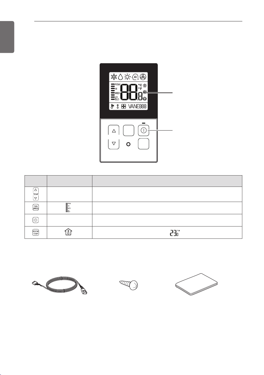
PART DESCRIPTION
TEMP
FAN
SPEED
ROOM
TEMP
Control button
Display screen
6
ENGLISH
PART DESCRIPTION
Using the remote control
Control
panel
Display screen Description
Accessory
Connection Cable
(1EA, 10m)
18~30°C
Temperature adjustment button: Adjusts the room temperature when
cooling and heating.
Indoor fan speed button: Adjusts the fan speed.
On/Off button: Turns the power on/off.
Displays the room temperature.
Screw
(2 EA)
Ex)
Quick Guide
INSTALLATION INSTRUCTION
Wall
Side
Wall
Side
<Connecting order>
Wall
Side
Wall
Side
<Separating order>
<Wire guide grooves>
INSTALLATION INSTRUCTION
7
ENGLISH
1 Please fix tightly using provided screw
after placing remote controller setup board
on the place where you like to setup.
- Please set it up not to bend because poor
setup could take place if setup board
bends.
Please set up remote controller board fit
to the reclamation box if there is a reclamation box.
2 Can set up Wired remote controller cable
into three directions.
- Setup direction: the surface of wall reclamation, upper, right
- If setting up remote controller cable into
upper and right side, please set up after
removing remote controller cable guide
groove.
h Remove guide groove with long nose.
3 Please fix remote controller upper part into
the backplate attached to the surface of
the wall, as the picture below, and then,
connect with backplate by pressing lower
part.
- Please make sure to leave no gaps on
the top, bottom, left or right sides
between the remote controller and backplate.
- Before assembly with the backplate,
arrange the Cable not to interfere with
circuit parts.
Remove remote controller by inserting a
screwdriver into the lower separating
holes and twisting to release the controller
from backplate.
- There are two separating holes. Please
individually separate one at a time.
- Please be careful not to damage the
inside
components when separating.
① Reclamation to the surface of the wall
② Upper part guide groove
③ Right part guide groove

8
ENGLISH
INSTALLATION INSTRUCTION
4 Please refer to the following directions
when connecting the indoor unit and the
wired remote controller together.
1) Please connect the cables as shown in the
figure below when connecting the plug
type cable from the indoor unit’s C/BOX
and the housing type of the extension
cable.
Please check if connector
is normally connected.
FAN
SPEED
TEMP
ROOM
TEMP
C/BOX Cable (Plug type)
Connecting
cable
Signal Yellow
12V Red
GND Black
CAUTION
!
Specification of LG supplied extension
cable: AWG#22, 3 core shielded. (Model :
PZCWRC1)
* Apply enclosed noncombustible con-
duit(metal raceway) totally or use FT-6
rated cable or above level in case of
local electric & building code that
requires plenum (CMP) cable usage.
2) When connecting Terminal Blocks of the
indoor C/BOX and the wired remote controller with the extension cable, refer to the
steps below.
① Remove the screw on the cable which is
fastened to the wired remote controller’s
Terminal Block by loosening with a screw
driver.
② Remove the housing of the provided 32ft
extension cable with a cutting nipper and
peel it as shown in the figure below. (when
purchasing the extension cable at the site
directly, please peel it as shown in the figure below.)
Indoor
Unit
side
③ Make sure each wire is securely fastened
under each screw terminal and the wires
are not in contact with each other.
④ Please connect the Terminal blocks of
indoor unit’s C/BOX and wired remote controller by referring to the images and contents shown below.
Connect the yellow(signal) part of the wired
remote controller’s terminal block and the
‘YL’ part of the indoor unit’s terminal block.
Connect the red(12V) part of the wired
remote controller’s terminal block and the
‘RD’ part of the indoor unit’s terminal block.
Connect the black(GND) part of the wired
remote controller’s terminal block and the
‘BK’ part of the indoor unit’s terminal block.
Remote
controller PCB
YELLOW RED BLACK
Signal 12V GND
Indoor
unit side
<Remote controller> <Indoor Terminal Block>
Remote controller
PCB Terminal block
Remark
Indoor
Terminal
block
Function
YELLOW YL Signal
RED RD 12V
BLACK BK GND
* In case of loosened screws or insufficient
contact between the terminal and the wire,
remote controller may not function properly.
* When the power is off on the remote con-
troller, check the connection between the
remote controller and Terminal Block.
* Use an appropriate screwdriver for tighten-
ing the terminal screws. A screwdriver with
a small head will strip the head and make
proper tightening impossible.
* Over-tightening the terminal screws may
break wires and terminal block structure.
0.394 inch(10mm) ± 0.118 inch(3mm)
1.378 inch(35mm)
±0.197 inch(5mm)

INSTALLATION INSTRUCTION
9
ENGLISH
CAUTION
!
• Installation work must be performed in
accordance with the national wiring standards and local by
authorized personnel only.
• Installations must comply with the applicable local/national or international standards.
• AWG#22, 3 core shielded is recommended when using the large hole in the center of the back plate.
• AWG#24, 3 core shielded is recommended when using the side or top knock-out
of the back plate.
5 Please use an extension cable if the dis-
tance between the wired remote controller
and the indoor unit is longer than
32ft(10m).
CAUTION
!
When installing the wired remote controller, do not bury it in the wall. (It can
cause damage in the temperature sensor.)
Do not install the cable to be 164ft(50m) or
longer. (It can cause communication error.)
Remote controller installation
Since the room temperature sensor is in the
remote controller, the remote controller box
should be installed in a place away from direct
sunlight, high humidity and direct supply of
cold air to maintain proper space temperature.
Install the remote controller about 5ft(1.5m)
above the floor in an area with good air circulation at an average temperature.
Do not install the remote controller where it
can be affected by:
- Drafts, or dead spots behind doors and in
corners.
- Hot or cold air from ducts.
- Radiant heat from sun or appliances.
- Concealed pipes and chimneys.
- Uncontrolled areas such as an outside wall
behind the remote controller.
- This remote controller is equipped with LCD.
display. For proper display of the remote controller LCD's, the remote controller should be
installed properly as shown in Fig.1.
(The standard height is 4~5 ft (1.2~1.5 m)
from floor level.)
Direct
Sun ray contact area
yes
FAN
SPEED
TEMP
OPER
MODE
FAN
SPEED
TEMP
no
FAN
SPEED
TEMP
OPER
MODE
no
OPER
MODE
5feet
(1.5meters)
FAN
SPEED
TEMP
OPER
MODE
no
(Fig. 1)

10
GND
GND
12V
Signal wire
Signal wire
TEMP
FAN
SPEED
ROOM
TEMP
GND
12V
B Y R B Y R
MASTER SLAVE
Signal wire
GND
12V
Signal wire
TEMP
FAN
SPEED
ROOM
TEMP
TEMP
FAN
SPEED
ROOM
TEMP
ENGLISH
INSTALLATION INSTRUCTION
Group Control
1 When installing more than 2 units of air
conditioner to one wired remote controller,
please connect as the right figure.
- If it is not event communication indoor
unit, set the unit as slave.
- Check for event communication through
the product manual.
2 When installing more than 2 wired remote
controllers to one air conditioner, please
connect as the right picture.
- When installing more than 2 units of
wired remote controller to one air conditioner, set one wired remote controller as
master and the others all as slaves, as
shown in the right picture.
- You cannot control the group as shown in
the right for some products.
- Refer to the product manual for more
detail. When controlling multiple indoor
units with event communication function
with one remote controller, you must
change the master/slave setting from the
indoor unit.
- For ceiling type cassette and duct product group, change the switch setting of
the indoor PCB.
- For wall-mount type and stand type product, change the master/slave setting with
the wireless remote controller. (Refer to
wireless remote controller manual for
detail)
h When installing 2 remote controllers to
one indoor unit with event communication function, set the master/slave of
the remote controller. (Refer to remote
controller master/slave selection)
When controlling the group, some functions excluding basic operation setting,
fan level
Min/Mid/Max, remote controller lock
setting and time setting may be limited.
3 When installing more than 2 wired remote
controllers to one air conditioner, please
connect as the right picture.
- When installing more than 2 units of
wired remote controller to one air conditioner, set one wired remote controller as
master and the others all as slaves, as
shown in the right picture.
- You cannot control the group as shown in
the right for some products.
- Refer to the product manual for more
detail.
1ON2345678
#3 switch OFF: Master
(Factory default setting)
1ON2345678
#3 switch ON: Slave
- When controlling in groups, set the
master/slave of the remote controller.
Refer to Installer setting section on how
to set master/slave for more detail.

INSTALLATION INSTRUCTION
11
ENGLISH
Install Setting
How to enter installer setting mode
CAUTION
!
• Installer setting mode is to set the
detail function of the remote controller.
If the installer setting mode is not set
correctly, it can cause problems to the
product, user injury or property damage. This must be set by an certificated
installer, and any installation or change
that is carried out by a non-certificated
person should be responsible for the
results. In this case, free service cannot
be provided.
1 If you want to set installer setting mode,
Press the Temperature up button and the
Room Temp button same time for five seconds.
2 When you enter the setting mode Initially.
Function code is displayed on the LCD
screen.
Function Code
Value
- Some categories of the menu may not
be displayed according to the function
of the product, or the menu name may
be different.
TEMP
FAN
SPEED
ROOM
TEMP

INSTALLATION INSTRUCTION
12
ENGLISH
<Installer Setting Code Table>
1 General air-conditioner product
No. Function Code Value
1
2
3
4
5
6
7
8
9
10
11
12
Te st Run 01 01:Set
Address Setting 02 00~FF : Address
E.S.P. Value 03
Thermistor 04
Ceiling Height 05
Static Pressure 06
Master Setting 07
Celsius
Fahrenheit
Switching
Celsius Control 17
Refrigerant
Leak Detector
Static Pressure Step 32
CN_EXT setting 52
<ESP Step> <ESP Value> <Example>
01:VeryLow 0 ~ 255
02:Low
03:Med
04:High
05:Very High
01:Remo
02:Indoor
03:2TH
01:Med
02:Low
03:High
04:Very High
01:V-H
02:F-H
03:V-L
04:F-L
00:Slave
01:Master
00:Celsius
12
01:Fahrenheit
00 : 1 °C Control
01 : 0.5 °C Control
00 : Not installed
29
01 : Installed
00 : use static pressure (code 06) set value
01~ 11: static pressure step (code 32) set value
00: Not use
01: Simple operation On/Off
02: Simple dry contact (It takes HL when operation is off.)
03: Indoor unit single emergency stop
04: Occupied / unoccupied
05: Indoor unit all emergency stop
h
It can be set only when there is indoor unit
emergency stop function.
06: Window contact
h
It can be set only when there is window contact
function.
07: Window contact lock
h
It can be set only when there is window contact lock
function.
(Optimized only for U.S.A)
Function Code ESP valueESP step

INSTALLATION INSTRUCTION
No. Function Code Value
0: Not use
1: Auto
200: Manual (190 V)
201: Manual (200 V)
202: Manual (210 V)
13
h Some contents may not be displayed depending on the product function
Auto ESP 68
203: Manual (220 V)
204: Manual (230 V)
205: Manual (240 V)
206: Manual (250 V)
207: Manual (260 V)
208: Manual (270 V)
3: Pass
4: Fail
13
ENGLISH

14
Function Code
Value
Function Code
Value
Group number
Control button
TEMP
ENGLISH
INSTALLATION INSTRUCTION
Test Run Mode
After installing the product, you must a test
Run Mode. For details related to the Product
manual.
1 Press button and button simulta-
neously for more than 3 seconds.
2 Setup figure ’01’ blinks
3 Press button to start.
Setting Address of Central control
It’s the functional to use connecting central
control.
1 Press button and button simulta-
neously for more than 3 seconds.
2 Setup function code ’02’ pressing by
button.
3 Set group number and indoor number.
4 Press button to save.
5 Press button and button simulta-
neously for more than 3 seconds After the
setting has been completed.
4 During the test run, pressing the below
button will exit run.
FAN
SPEED
TEMP
ROOM
TEMP
NOTE
!
• After setup, it automatically gets out of
setup mode if there is no button input
for 25seconds.
• When existing without pressing set button, the manipulated isn’t reflected.

INSTALLATION INSTRUCTION
Function Code
Value
ESP step
ESP Value
ESP step
TEMP
Function Code
Thermistor value
15
ENGLISH
E.S.P
This is the functional that decides the strenth
of the wind for each wind level and because
this function is to make the installation easier.
- If you set ESP incorrectly, the air conditional
may malfunction.
- This setting must be carried out by a certificated technician.
1 Press button and button simulta-
neously for more than 3 seconds.
2 Setup function code ’03’ pressing by
button.
3 Select ESP fan step and ESP value.
* ESP value range : 0~255
4 Press button to save.
5 Press button and button simulta-
neously for more than 3 seconds After the
setting has been completed.
NOTE
!
• When setting ESP value on the product
without very weak wind or power wind
function, it may not work.
• Please be careful not to change the ESP
value for each fan step.
• It does not work to setup ESP value for
very low/power step for some product.
• ESP value is available for specific range
belongs to the product.
Thermistor
This is the function to select the temprature
sensor to judge the room temperature.
1 Press button and button simulta-
neously for more than 3 seconds.
2 Setup function code ’04’ pressing by
button.
3 Set Thermistor value by pressing button by
pressing temperature button.
(01: Remote Controller, 02: Indoor, 03: 2TH)
4 Press button to save.
5 Press button and button simulta-
neously for more than 3 seconds After the
setting has been completed.
NOTE
!
h The function of 2TH has difference
operation characterics according to
product.
• Cooling: Operation of higher temperature by comparing indoor unit’s and
wired remote controller’s temperature.
(there are products that operate at a
lower temperature.)
• Heating: Operation of lower temperature
by comparing indoor unit’s and wired
remote controller’s temperature.

16
Function Code
Function Code
Value
Thermistor value
ENGLISH
INSTALLATION INSTRUCTION
Ceiling Height Selection
This function is to adjust FAN Airflow rate
according to ceiling height (For ceiling type
product)
1 Press button and button simulta-
neously for more than 3 seconds.
2 Setup function code ’05’ pressing by
button.
3 Set Thermistor value by pressing button by
pressing temperature button.
(01: Remote Controller, 02: Indoor, 03:
2TH)
4 Press button to save.
Static Pressure Setting
This function is applied to only duct type.
Setting this in cases will cause malfunction.
1 Press button and button simulta-
neously for more than 3 seconds.
2 Setup function code ’06’ pressing by
button.
3 Set Thermistor value by pressing button by
pressing temperature button.
(01: V-H, 02: F-H, 03: V-L, 04:F-L)
Pressure
selection
01 V-H Variable High
02 F-H Fixed High
03 V-L Variable Low
04 F-L Fixed Low
Zone
state
Function
ESP
standard
value
5 Press button and button simulta-
neously for more than 3 seconds After the
setting has been completed.
NOTE
!
• Ceiling height setting is available only for
some products.
• Ceiling height of “Very high” function
may not exist depending on the indoor
units.
• Refer to the product manual for more
details.
4 Press button to save.
5 Press button and button simulta-
neously for more than 3 seconds After the
setting has been completed.

INSTALLATION INSTRUCTION
Function Code
Fahrenheit setting
value
Function Code
Master/Slave Value
17
ENGLISH
Remote Controller Master/Slave
Setting
It’s a function for setting in group control, or 2remote controller control.
1 Press button and button simulta-
neously for more than 3 seconds.
2 Setup function code ’07’ pressing by
button.
3 Select Master/Slave by pressing tempera-
ture button. (00: Slave, 01: Master)
4 Press button to save.
Fahrenheit Switching
This function is used for switching the display
between Celsius and Fahrenheit.
(Optimized only for U.S.A)
1 Press button and button simulta-
neously for more than 3 seconds.
2 Setup function code ’12’ pressing by
button.
3 Select Temperature unit mode by tempera-
ture button.
(00: Celsius , 02: Fahrenheit)
5 Press button and button simulta-
neously for more than 3 seconds After the
setting has been completed.
Remote
Controller
Indoor unit operates based on
Master
Slave
-
• When controlling in groups, basic operation
settings, airflow strength
weak/medium/strong, lock setting of the
remote controller, time settings, and other
functions may be restricted.
master remote controller at
group control. (master is set
when delivering from the warehouse.)
Setup all remote controllers
except one master remote controller to slave at group control.
Refer to eh ‘Group control’ part for details.
Function
4 Press button to save.
5 Press button and button simulta-
neously for more than 3 seconds After the
setting has been completed.
h Whenever press button in
Fahrenheit mode, the temperature will
increase/drop 2 degrees.

INSTALLATION INSTRUCTION
Function Code
value
Function Code
value
18
ENGLISH
Celsius Control Setting Setting for Refrigerant Leak
This function is to set the unit for temperature
control by 1°C or 0.5°C.
1 Press button and button simulta-
neously for more than 3 seconds.
2 Setup function code ’17’ pressing by
button.
3 Select Temperature unit mode by tempera-
ture button.
(00: 1 °C Control, 01: 0.5 °C Control)
Detector
This function is used when a refrigerant leak
detector is additionally installed in the indoor
unit or the installed detector is removed.
1 Press button and button simulta-
neously for more than 3 seconds.
2 Setup function code ’29’ pressing by
button.
3 Select Refrigerant Leak Detector by tem-
perature button.
(00: Not installed , 01: Installed)
4 Press button to save.
5 Press button and button simulta-
neously for more than 3 seconds After the
setting has been completed.
4 Press button to save.
5 Press button and button simulta-
neously for more than 3 seconds After the
setting has been completed.

INSTALLATION INSTRUCTION
Function Code
Function Code
value
value
19
ENGLISH
Static Pressure Step Setting
This is the function that static pressure of the
product is divided in 11 steps for setting.
1 Press button and button simulta-
neously for more than 3 seconds.
2 Setup function code ’32’ pressing by
button.
3 Select Static Pressure Step Setting by
temperature button.
CN_EXT setting
It is the function to set to control the external
input and output according to DI/DO set by
the customer using the indoor unit’s Dry
Contact Port. (It is the function to decide the
usage of the contact point port (CN_EXT)
mounted in the indoor unit PCB.)
1 Press button and button simulta-
neously for more than 3 seconds.
2 Setup function code ’52’ pressing by
button.
3 Select the desired setting value with the
temperature up(▲), down(▼) button.
4 Press button to save.
5 Press button and button simulta-
neously for more than 3 seconds After the
setting has been completed.
4 Press button to save.
5 Press button and button simulta-
neously for more than 3 seconds After the
setting has been completed.
Value
00
Not use
01
Simple operation On/Off
Simple dry contact (It takes HL when
02
operation is off.)
03
Indoor unit single emergency stop
04
Occupied / unoccupied
Indoor unit all emergency stop
05
h
It can be set only when there is indoor
unit emergency stop function.
Window contact
06
h
It can be set only when there is
window contact function.
Window contact lock
07
h
It can be set only when there is
window contact lock function.
Description

INSTALLATION INSTRUCTION
20
ENGLISH
Auto ESP
This function automatically sets the rotation
speed of the fans corresponding to each step
of rated airflow for easy installation.
1 Press button and button
simultaneously for more than 3 seconds.
2 Setup function code ’68’ pressing by
button.
Function code
Value 1 : Auto ESP mode
Value 2 : Manual step
3 Select the desired setting value with the
temperature up(▲), down(▼) button.
4 Press button to save.
5 Press button and button
simultaneously for more than 3 seconds
After the setting has been completed.
※ The voltage can be set by setting the Auto
ESP Mode to 'Manual (2)', then pressing
the `Fanspeed` button.
※ While 'Auto ESP' is being set, the display
on the wired remote control changes as
shown below, and the wired remote
control cannot be operated.
※ Once the set-up is complete, you can enter
installer setup (68) to check whether the
set-up has succeeded or failed.
(3: Success, 4: Failure)
Value 1
(Auto ESP
mode)
(Not use)
(Auto)
(Manual)
Value 2
(Manual
Step)
0
1
2
3-
4-
--
--
00 190 V
01 200 V
02 210 V
03 220 V
04 230 V
05 240 V
06 250 V
07 260 V
08 270 V
Description
(Voltage setting)
Cannot be set, only
monitoring is possible.
If the value1 is 3, setting is
successful.
Cannot be set, only
monitoring is possible.
If the value1 is 4, setting
has failed.

OWNER'S INSTRUCTION
OWNER'S INSTRUCTION
21
ENGLISH
Standard Operation
h The operation mode can be set from
Central Controller only.
Cooling Mode
It cools the room by comfortable and Clean
wind.
1 Press the button.
2 Adjust the desired temperature by press
the temperature button.
(Temp range : 18°C~30°C (64°F~86°F)
Heating Mode
It supplies warm wind to the indoor.
1 Press the button.
2 When the room temperature is lower than
the desired temperature
: Heating Operation starts (For Heat Pump
models only)
When the room temperature is higher than
the desired temperature
: Cooling Operation starts
Dehumidification Mode
It removes humidity while air-cooling Weakly.
1 Press the button.
1 Press the button.
2 Adjust the desired temperature by press
the temperature button.
(Temp range : 16°C~30°C (60°F~86°F)
Auto Operation Mode
It makes the room cool using pleasant and
fresh air quickly
Fan Mode
It blows the air as it is in the indoor, not the
cold wind.
1 Press the button.
h Temperature control is not available during
the Dehumidification & Fan operation.

22
Fan Speed Selection in Cooling Operation
Fan Speed Selection in Heating, Dry, Fan,
Auto-Operation
ENGLISH
OWNER'S INSTRUCTION
Function setting
Fan Speed Selection
You can easily control the fan speed.
1 Press the button.
2 Press the button.
Room Temperature Check
1 Press the button.
NOTE
!
• “To change the temperature display to
Celsius or Fahrenheit, change LCD display by referring to page 14.”
• As the temperature distribution of the
remote controller installation space is
not Uniform, slight difference can be
generated between the actually felt temperature and the room temperature indication of the remote controller.
Child Lock
It is the function to use preventing children
or others from careless using.
NOTE
!
• If the product is not compatible with
The fan speed control, it will not function as per your selection.
1 Press button and button
Simultaneouslly for more than 3 seconds.
NOTE
!
•
After the setting of the ‘CL’, if another
button is setup , the button can not be
recognized as the ‘CL’ is indicated at
the temperature display section.
 Loading...