

Page 1

LG
BNU-LW(Lonworks Gateway)
Owner's / Installation Manual
LG
IMPORTANT
• Please read this Installation Manual carefully and
thoroughly before installing and operating your room air
conditioner.
• Please retain this Installation Manual for future reference
after reading it thoroughly.
Page 2

2 Lonworks Gateway
BNU-LW (Lonworks Gateway)
TABLE OF CONTENTS
■ Safety Precautions
..............................................................................
3
■ BNU-L W Configur ation
.......................................................................
7
• BNU-L W Accessory P arts
................................................................
7
• Name of each part
............................................................................
8
■ System Structure
................................................................................
9
■ Address of the indoor unit connected to the BNU-LW
(LonWorks Gateway)
.......................................................................
10
■ Communications Wire Specifications
...............................................
11
■ General Specifications
......................................................................
12
■ Installation procedure of the BNU-LW(Lonworks gatewa y)
.............13
■ Wiring procedure of the BNU-L W
.....................................................
14
■ Appendix
...........................................................................................
15
■ The relationship between indoor unit address
and network variable
........................................................................
16
■ Network V ariables
.............................................................................
16
Page 3
Safety Precautions
Installation Manual 3
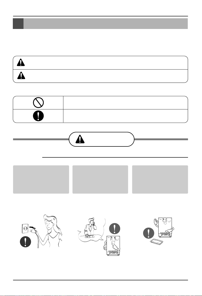
Do not operate or stop
the unit by inserting or
pulling out the power
plug.
• It will cause electric shock
or fire due to heat
generation.
Ask for Product
equipment at the service
center or establishment
certainly at the specialty
store.
• It can cause an accident,
electric shock, explosion
or injury.
Use standard parts.
• Use of non standard parts
can cause electric shock,
explosion, injury,
breakdown.
■ Operation
Safety Precautions
To prevent injury to the user or other people and property damage, the following instructions
must be followed.
■ Incorrect operation due to ignoring instruction will cause harm or damage. The seriousness is
classified by the following indications.
■ Meanings of symbols used in this manual are as shown below.
This symbol indicates the possibility of death or serious injury.
This symbol indicates the possibility of injury or damage.
Be sure not to do.
Be sure to follow the instruction.
WARNING
WARNING
CAUTION
BNU-LW
BNU-LW
Standard Parts
Page 4
Safety Precautions
4 Lonworks Gateway
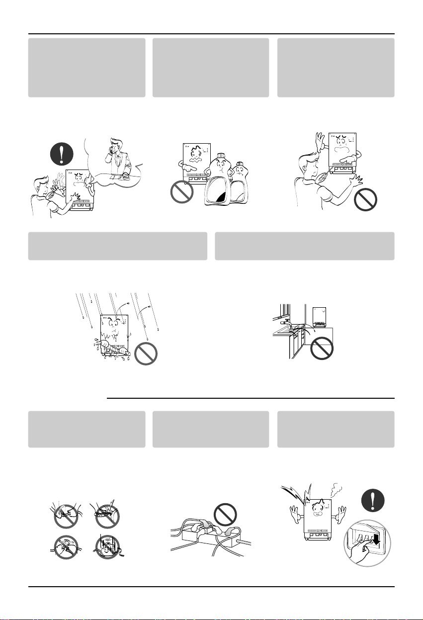
If water enters the product, turn the power
switch of the main body of appliance off.
• After taking the power-plug out from the
socket, contact the service center.
Keep the product away from the places
which can have moisture.
• Water may enter the unit and degrade the
insulation. It may cause an electric shock.
BNU-LW
■ During usage
While re-installing the
established product, notify
the service center or
establishment specialty
store.
• It can cause an accident,
electric shock, explosion,
injury.shock.
Do not use the power cord
near Flammable gas or
combustibles, such as
gasoline, benzene, thinner,
etc.
• It may cause an explosion
or fire
Do not disjoint randomly or
repair and remodel the
product.
• It may cause fire and
electric shock
BNU-LW
BNU-LW
Do not change or extend the
conductor at random.
• It can cause fire and
electric shock.
Do not use concert with in
the octopus-like legs way.
• It can cause fire and
electric shock
Unplug the unit if strange
sounds, smell, or smoke
comes from it.
• It may cause fire and
electric shock accident.
BNU-LW
BNU-LW
BNU-LW
Thinner
Wax
Page 5

Safety Precautions
Installation Manual 5
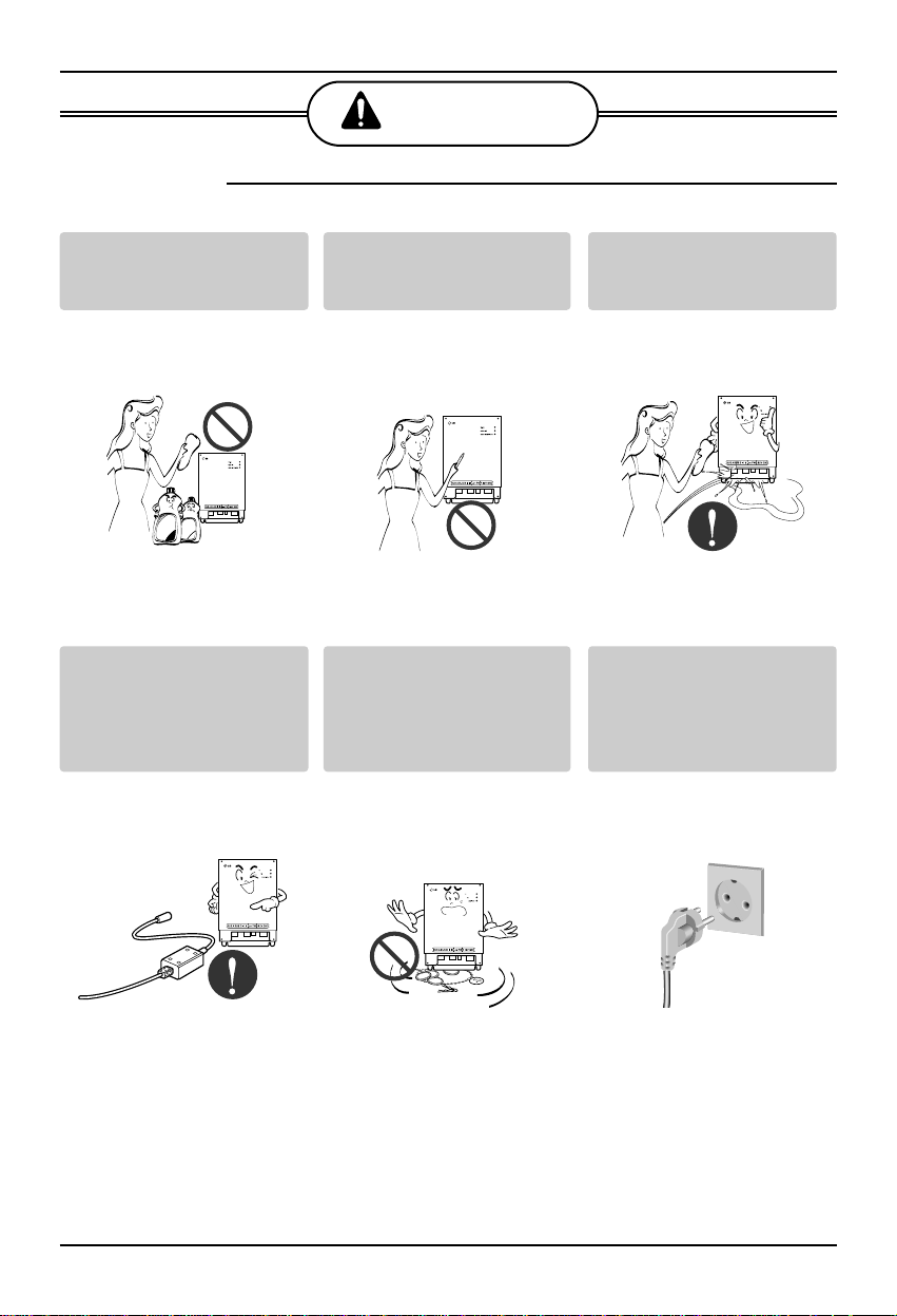
Do not put firearms near
product.
• It can cause fire.
Do not put an electric heater
or conductor near to the
product.
• It can cause fire and
electric shock.
Do not spill water inside
product.
• It can cause electric
shock and breakdown.
BNU-LW
BNU-LW
BNU-LW
Do not place heavy goods
on wire.
• It can cause fire and
electric shock.
Hold the plug by the head of
the power plug when taking
it out.
• It may cause electric
shock and damage.
Do not place heavy goods
on product.
• It can cause product
breakdown.
BNU-LW
BNU-LW
That increase in case of
product was been flood
certainly in the service
center or establishment
specialty store commit .
• I am responsible for fire
and electric shock.
Protect the product from
handling by a children.
• It can cause accident and
product breakdown.
Do not apply shock to
product.
• I am responsible for
breakdown in case of
shock to product.
BNU-LW
BNU-LW
BNU-LW
Page 6
Safety Precautions
6 Lonworks Gateway
■ During usage
CAUTION
Clean by soft hands using a
cleaning material like a soft
cloth.
• It can result in fire and
product transformation.
Use touch screen with a pen
that product offers.
• Otherwise, there can be
breakdown and damage
to the product.
Do not place any live part on
the surface having water.
• It can cause product
breakdown.
BNU-LW
Wax
Thinner
BNU-LW
BNU-LW
Use recommended Adapter.
• Otherwise it can result in
product breakdown
Avoid contact to the metallic
goods such as necklace,
coin, key, a watch which
may touch the battery even
for a short-time.
• It may cause product
breakdown and injury.
Hold the plug by the head of
the power plug when taking
it out.
• It may cause electric
shock and damage.
BNU-LW
BNU-LW
Page 7

BNU-LW Configuration
Installation Manual 7
BNU-LW Configuration
BNU-LW Accessory Parts
BNU-LW
BNU-LW Front view
Power Supply External S.M.P.S Power : 100~250 VAC
50/60 Hz Input
Page 8

BNU-LW Configuration
8 Lonworks Gateway
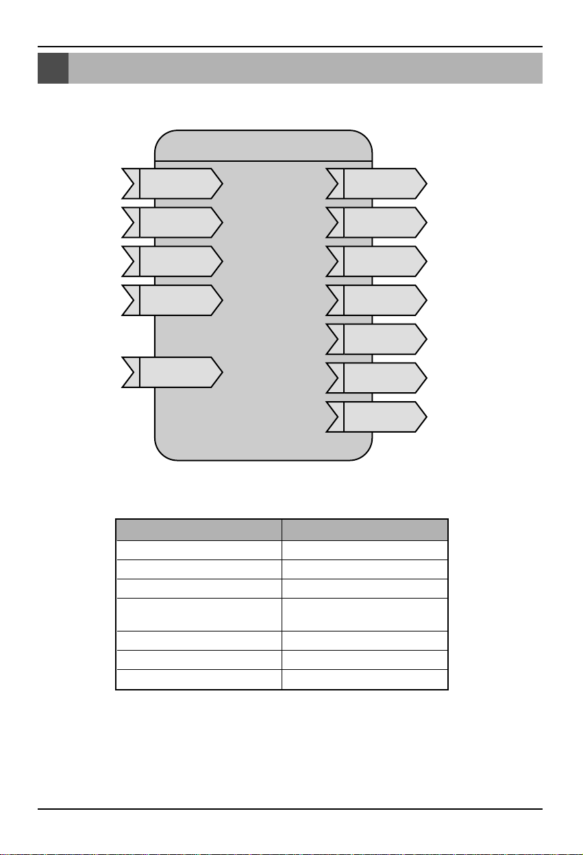
Name of each part
BUS_A: RS485 Communications cable
A (+)
BUS_B: RS485 Communications cable
B (-)
T1, T2: For reserve(not use)
LON: TP/FT-10 Communications wire
(no polarity)
- LonWorks system
communications wire
PWR: Connect to DC 12V power
adapter
12V: Connect when not using the DC
12V power adapter
GND: Connect when not using the DC
12V power adapter
WINK: It flashes 5 times when receiving
the WINK command from the
LonWorks system. (Green)
Service: It will stay off for normal status
and flash when it is not
connected to the LonWorks
system (Red)
It will be turned on when you
press the service switch.
Service switch: When you press the
switch, the Neuron ID
will be transmitted to
the LonWorks system
and the service LED will
be turned on.
1
2
3
4
5
6
7
8
BNU-LW
1
8
2
3
4
5
6
7
Both 5 and 6/7 are for power supply and only one of the two needs to be connected.
When connecting 5, do not use 6/7.
When connecting 6/7, do not use 5.
WARNING
Page 9

System Structure
Installation Manual 9
System Structure
LonWorks Gateway can be connected to maximum of 64 indoor units.
BNU-LW(LonWorks Gateway) cannot be connected to I-gateway (CNU), PC central controller, Deluxe
central controller and simple central controller at the same time.
ON
L1 2 3 4
KSDO4H ON
L1 2 3 4
KSDO4H
LonWorks* Network
Max. 64 indoor & 8 outdoor
LonWorks* Gateway
RS485
PI485
PI485
LonWorks-compatible
BMS
Page 10

Address of the indoor unit connected to the BNU-LW(LonWorks Gateway)
10 Lonworks Gateway
Address of the indoor unit connected to the BNU-LW(LonWorks Gateway)
Indoor unit address can be from (0,0) to (3,F) as shown at figure.
ON
L1 2 3 4
KSDO4HON
L1 2 3 4
KSDO4HON
L1 2 3 4
KSDO4HON
L1 2 3 4
KSDO4H
LonWorks-compatible
BMS system
(Indoor units: Maximum of 64 units)
LonWorks*
Gateway
RS485
PI485
A/C No.
12 3
(0.0) (0.1) (0.F)
17 28 32
(1.0) (1.1) (1.F)
33 34 48
(2.0) (2.1) (2.F)
49 50 64
(3.0) (3.1) (3.F)
address
A/C No.
address
A/C No.
address
A/C No.
address
PI485
PI485
PI485
Page 11

Communications Wire Specifications
Installation Manual 11
Communications Wire Specifications
1. RS485 Communications Wire spec : 0.75 mm2 2C Shield, product to product : 200M, Total
Length : 1kM
2. FT-10 Communications Wire spec : see below table
*Node to node distance(max) : 200M, Total length : 450M
Cable Type AWG Diameter
TIA 568A Category 5 cable 24WAWG 0.5mm
Belden 88471 (PVC jacket) or 16AWG 1.3mm
equivalent cable
Belden 85102(Tefzel jacket) or equal 16AWG 1.3mm
cable
Level IV cable 22AWG 0.65mm
JY(st)Y 2x2x0.8 20.4WG 0.8mm
Page 12

General Specifications
12 Lonworks Gateway
General Specifications
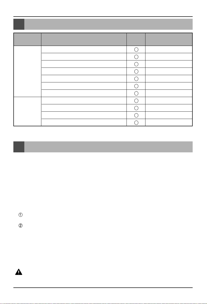
Item Description
Neuron Chip FT3150 Smart Transceiver / 10 MHz
Supply Voltage DC 9 ~ 12V
Network Transceiver FT-X1 Communication Transformer (Free Topology 78kbps)
RS485 Connector LG-Net(connects to PI485)
LonWorks FT-10 Connector (connects to BMS)
Channel Type FT-10
Dimension(W H D) 178mm 237mm 50mm
Power LED
Service LED
LED Indicator Wink LED
LG-Net TX/RX LED
LonWorks TX/RX LED
Switch Service Pin(switch)
XIF File
See technical support part at http://www.lge.com/airconditioner
See network solution part at http://www.systemaircon.com
Page 13
Installation procedure of the BNU-LW(Lonworks gateway)
Installation Manual 13
General Specifications
Installation procedure of the BNU-LW(Lonworks gateway)
1. Setup the central controller address of the indoor unit and the DIP S/W of PI485 accordingly to the
product.(Refer to the PI485 installation manual for details.)
- Fourth Dip s/w of PI485 must be OFF.
2. Connect BUS_A and BUS_B (485 Communications cable) while properly checking the connecting
polarity. (Refer to next page)
3. LON (Connect TP/FT-10 cable to LonWorks Gateway communications cable) TP/FT-10
communications cable does not have the polarity.
Connect 2 communications cables to Lonworks System.
4. PWR (Power supply)
For the power, select one of the two following options.
When you are using DC 12V power adapter
Connect to 5 in Name of each part.
When you can supply another DC 12V power at your site(building)
Connect 12V and GND to 6 and 7 connector respectively.
5. If you press the Service Switch after connecting to the LonWorks system, the Service LED would
light up and the Neuron ID will automatically be transmitted to LonWorks system.
6. Check whether the Service LED turns to normal status (off) within 10 minutes.
If the Service LED turns to normal status, it the installation has been completely normally.
7. Appendix is the necessary information to BMS company using Lonworks system.
Function Remark
ON/OFF command/monitoring
SetTemp command/monitoring
SetMode command/montioring
SetFanSpeed command/monitoring
Lock command/monitoring
Error Code monitoring
All Off/All On command/monitoring
ON/OFF command(nviOnOff)
All Off/All On command(nviAllOnOff)
Other command(nviSetTemp,Mode)
Monitoring
possible
Control &
Monitoring
Directly
Binding
Function
Keep aware of connecting terminal block(Do not use the automatic driver)
WARNING
Set HeartBeat = O when binding connection between other Lonworks device output and indoor unit input.
Otherwise you cannot control the indoor unit by remote controller(wired/wireless).
Page 14

Wiring procedure of the BNU-LW
14 Lonworks Gateway
Wiring procedure of the BNU-LW
A
B
+10V
GND
PI485
RS -485
TP/FT-10
(Twisted Pair Cable)
LonWorks
Adapter
Pow er
BMS Control (PC)
[Wiring sequence]
1. Connect the 485 communications cable.
- Be careful of the polarity
2. Connect the LonWorks communications wire (TP/FT-10)
- No polarity
3. Power supply
Select one of the two options.
Use DC 12V adapter
- Connect to 5 connector in Name of each part.
Supply DC 12V at installation site
- Connect 12V and GND to 6 and 7 connector respectively.
Page 15
Appendix
Installation Manual 15
Appendix
• You can control and monitor as shown in the figure for one air
conditioner.
• Network variable can be different from real value.
Refer XIF file at the company website for detail information.
Air conditioner
Control network variable
Air conditioner
Status monitoring network variable
The appendix is not needed for the actual installation but includes necessary information for BMS
operation.
Indoor_nn (nn : 00~63)
nviOnOff_nn
SNVT_switch
ID : 95
nvoOnOff_nn
SNVT_switch
ID : 95
nvoMode_nn
SNVT_hvac_mode
ID : 108
nvoFanSpeed_nn
SNVT_switch
ID : 95
nvoLock_nn
SNVT_switch
ID : 95
nvoRoomTemp_nn
SNVT_temp_p
ID : 105
nvoSetTemp_nn
SNVT_temp_p
ID : 105
nvoError_nn
SNVT_count
ID : 8
nviMode_nn
SNVT_hvac_mode
ID : 108
nviFanSpeed_nn
SNVT_switch
ID : 95
nviLock_nn
SNVT_switch
ID : 95
nviSetTemp_nn
SNVT_temp_p
ID : 105
Controlling items Monitoring items
ON/OFF Command ON/OFF Status Report
Operation Mode Setting Operation Mode Status Report
Fan Speed Setting Fan Speed Status Report
Lock Setting
Lock Setting Report(Remote
Controller)
Temperature Setting Temperature Setting Report
Room Temperature Report
Error Code Report
Page 16

The relationship between indoor unit address and network variable
16 Lonworks Gateway
Network Variables
The relationship between indoor unit address and network variable
Refer PI485 manual for indoor unit address.
All On Off
nviAIIOnOff
SNVT_switch
ID : 95
A/C Object NV Name (Example : nviONOFF)
01~16 (0-0 ~ 0-15) Indoor_00 ~ Indoor_15 nviONOFF_01 ~ nviONOFF_16
17~32 (1-0 ~ 1-15) Indoor_16 ~ Indoor_31 nviONOFF_17 ~ nviONOFF_32
33~48 (2-0 ~ 2-15) Indoor_32 ~ Indoor_47 nviONOFF_33 ~ nviONOFF_48
49~64 (3-0 ~ 3-15) Indoor_48 ~ Indoor_63 nviONOFF_49 ~ nviONOFF_64
indoor unit address
Controlling items
All On and All Off(Command)
Function ON/OFF Command Input
INPUT Using NV network input variable : SNVT_switch nviOnOff_n
Operation Control ON/OFF for each indoor unit
Function ON/OFF Status Output
OUTPUT Using NV network output variable : SNVT_switch nvoOnOff_n
Operation Monitor ON/OFF for each indoor unit
NV Field Operation
value not used (set in 0% usually)
0 = Indoor unit Off
state 1 = Indoor unit On
Else = Indoor unit Off
Default Value
1) ON/OFF Input/Output
Valid Range
SNVT_switch
( ID : 95 )
Page 17

Network Variables
Installation Manual 17
Function Mode Command Input
INPUT Using NV network input variable : SNVT_hvac_mode nviMode_n
Operation Control running Mode for each indoor unit
Function Mode Status Output
OUTPUT Using NV network output variable : SNVT_hvac_mode nvoMode_n
Operation Monitor running Mode for each indoor unit
NV Operation
HVAC_AUTO : 0 = Auto Mode
HVAC_HEAT : 1 = Heat Mode
HVAC_COOL : 3 = Cool Mode
HVAC_PRE_COOL : 5 = Dry Mode
HVAC_FAN_ONLY : 9 = Fan Mode
Else = Fan Mode
2) Mode Input/Output
Valid Range
SNVT_hvac_mode
( ID : 108 )
Default Value
Function Fan Speed Command Input
INPUT Using NV network input variable : SNVT_switch nviFanSpeed_n
Operation Control fan speed for each indoor unit
Function Fan Speed Status Output
OUTPUT Using NV network output variable : SNVT_switch nvoFanSpeed_n
Operation Monitor fan speed for each indoor unit
NV Field Operation
value 0 ~ 25 = Fan Speed Low
25.5 ~50 = Fan Speed Mid
50.5 ~ 100 = Fan Speed High
Else = Fan Speed High
state not used
Default Value
3) Fan Speed Input/Output
Valid Range
SNVT_switch
( ID : 95 )
Page 18

Network Variables
18 Lonworks Gateway
Function Lock Command Input
INPUT Using NV network input variable : SNVT_switch nviLock_n
Operation Control Lock setting(wired remote controller) for each indoor unit
Function LockStatus Output
OUTPUT Using NV network output variable : SNVT_switch nvoLock_n
Operation Monitor Lock status(wired remote controller) for each indoor unit
NV Field Operation
value not used (set in 0% usually)
0 = Indoor unit Lock Off
state 1 = Indoor unit Lock On
Else = Indoor unit Lock Off
Default Value
4) Lock Input/Output
Valid Range
SNVT_switch
( ID : 95 )
Function Set Temperature Command Input
INPUT Using NV network input variable : SNVT_temp_p nviSetTemp_n
Operation Control set temperature for each indoor unit
Function Set Temperature Status Output
OUTPUT Using NV network output variable : SNVT_temp_p nvoSetTemp_n
Operation Monitor set temperature for each indoor unit
NV Operation
At Cool mode : 18 ~ 30 C
At Heat mode : 18 ~ 30 C
At Dry mode and Fan mode : Not available
Default Value
5) Set Temperature Input/Output
Valid Range
SNVT_temp_p
( ID : 105 )
Page 19

Network Variables
Installation Manual 19
Function Room Temperature Status Output
OUTPUT Using NV network output variable : SNVT_temp_p nvoRoomTemp_n
Operation Monitor set temperature for each indoor unit
NV Operation
At Cool mode : -10 ~ 40 C
At Heat mode : -10 ~ 40 C
At Dry, Fan mode : Not available
Default Value
6) Room Temperature Output
Valid Range
SNVT_temp_p
( ID : 105 )
Function Error Status Output
OUTPUT
Using NV network output variable : SNVT_switch nvoError
Operation Monitor error code for each indoor unit
NV Field Operation
value
0 = No Error
Else = Error Code
state not used
Default Value
7) Error Output
Valid Range
SNVT_count
( ID : 8 )
• Refer product manual for error code
Function All Off Command Input
INPUT Using NV Network input variable : SNVT
_
switch nviAllOnOff
Operation Control ON/OFF for all indoor unit
NV Field Operation
value not used
state
1 : All ON indoor unit
0 : All OFF indoor unit
Default Value
8) All ON/OFF indoor unit
Valid Range
SNVT_switch
( ID : 95 )
Page 20

P/No.: 3828A20494E
After reading this manual, keep it in a place easily accessible to the user for future reference.
Printed in Korea
 Loading...