

LG PQDSBCGCD0 User guide

P/NO : MFL42540218
www.lg.com
INSTALLATION MANUAL
• Please read this installation manual completely before installing the product.
• Installation work must be performed in accordance with the national wiring
standards by authorized personnel only.
• Please retain this installation manual for future reference after reading it
thoroughly.
TYPE : Dry contact for communication
Model : PQDSBCGCD0
ENGLISH
ITALIANO ESPAÑOL FRANÇAIS DEUTSCH

2 Dry contact for communication
Dry contact for communication Installation manual
TABLE OF CONTENTS
n Safety Precautions
.............................................................
3~4
n Name of each part
..................................................................
5
n Installation Method
.............................................................
6~7
Installation inside of the indoor unit..........................................................6
Installation outside of the indoor unit .......................................................7
n Setting and using method ................................................8~17
1. Power supply and indoor unit connection............................................8
2. Setting of input signal...................................................................9 ~ 10
3. Setting of ʻTEMP_SWʼ........................................................................11
4. Setting of ʻCONTROLMODE_SWʼ............................................12 ~ 16
5. Inoddr unit monitoring ........................................................................17
Safety Precautions
Installation manual 3
ENGLISH
Do not touch the board
when the power is
connected.
•
It can cause a fire, electric
shock, explosion, injury and
problem to the product.
Always request for
installation of the product
to the service center or
the installation service
provider.
•
It can cause a fire, electric
shock, explosion and injury.
When reinstalling the
previously installed product,
request for service to the
service center or the
installation service provider.
•
It can cause a fire, electric
shock, explosion and injury.
n During installation
Service center
Service center
Do not install the product where it can
be exposed to rain.
•
It can cause problems to the product.
Do not install the product in a humid
location.
•
It can cause problems to the product.
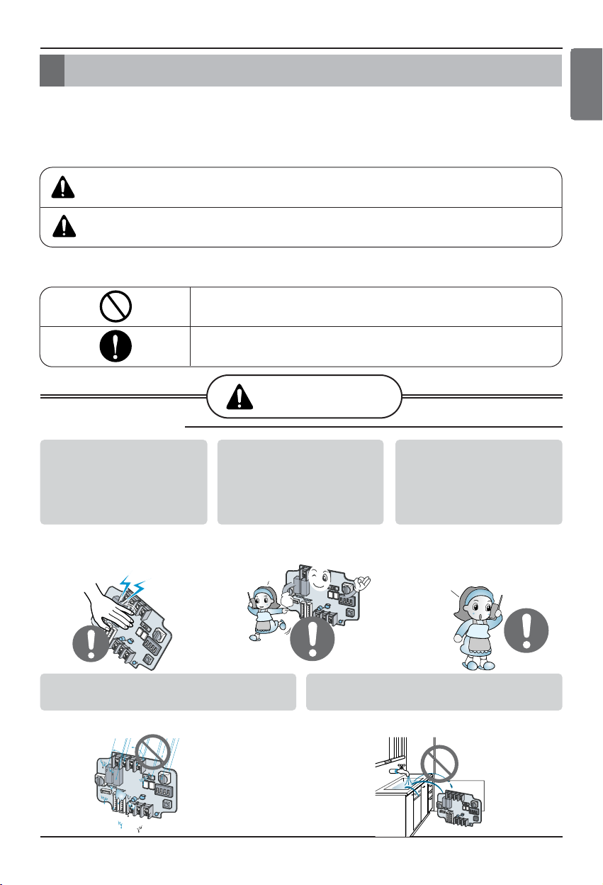
Safety Precautions
To prevent injury to the user or other people and property damage, the following instructions
must be followed.
n Incorrect operation due to ignoring instruction will cause harm or damage. The seriousness is
classified by the following indications.
n Meanings of symbols used in this manual are as shown below.
WARNING
CAUTION
This symbol indicates the possibility of death or serious injury.
This symbol indicates the possibility of injury or damage.
Be sure not to do.
Be sure to follow the instruction.
WARNING
Safety Precautions
4 Dry contact for communication
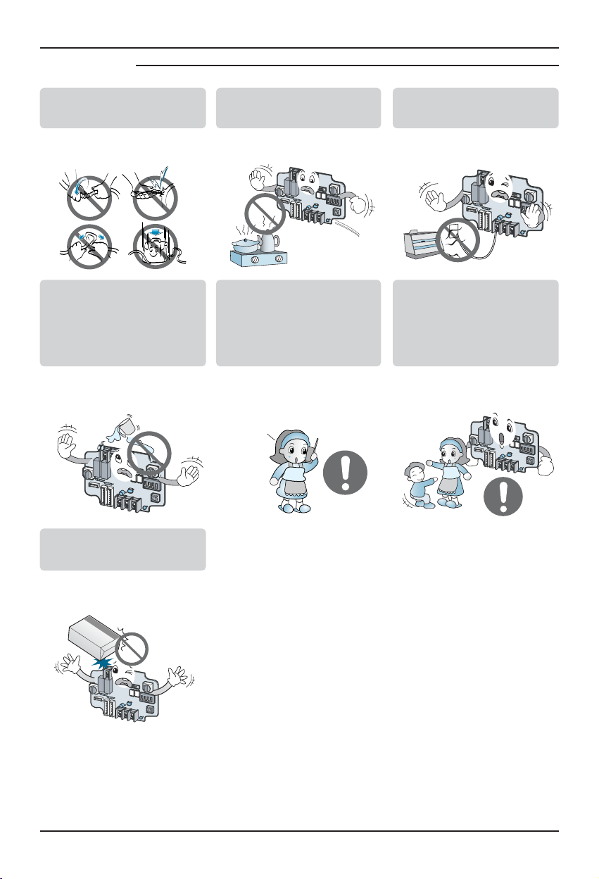
n During use
Do not modify or extend the
power cord.
• It can cause a fire and
electric shock.
Do not use any flaming
devices near the product.
• It can cause a fire.
Do not use any heating
devices near the power cord.
• It can cause a fire and
electric shock.
Do not pour water inside the
product.
• It can cause an electric
shock and problem to the
product.
When the product is
submersed in water, always
request for service to the
service center or the
installation service provider.
• It can cause a fire and
electric shock.
Make the children and the
elderly use the product with
the help of a guardian.
• It can cause a safety
accident and problems to the
product.
Do not give impact to the
product.
• It can cause problems to the
product.
Service center
Name of each part
Installation manual 5
ENGLISH
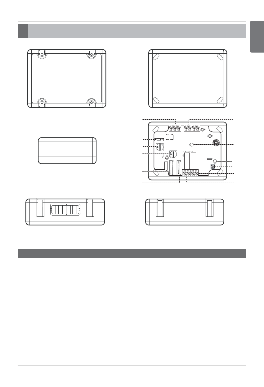
Name of each part
1. CN_INDOOR : Connector for indoor unit
2. CN_PI485 : PI485 connector
3. CHANGEOVER_SW : Switch to select External Voltage or Non Voltage for input contact signal
4. CN_CONTROL : Contact point signal input
5. CN_COM : Signal input for communication
6. CONTROLMODE_SW : Switch to select the control mode
7. TEMP_SW : Switch to set the desired temperature or indoor unit address
8. CN_OUT(O1,O2) : Output terminal to show whether the indoor unit is operating (Relay contact)
9. CN_OUT(E1,E2) : Output terminal to show whether there is an error with the indoor unit (Relay contact)
10. LED_DISPLAY : LED to display the status of Dry contact
11. RESET_SW : Reset switch
12. LED_485 : LED to display the status of communication
DRY CONTACT FOR COMMUNICATION
(Front case)
(Rear case)
4
5
3
6
7
(Top)
(Side) (Side)
1
2
(Internal PCB board)
12
10
11
9
8
Installation Method
6 Dry contact for communication
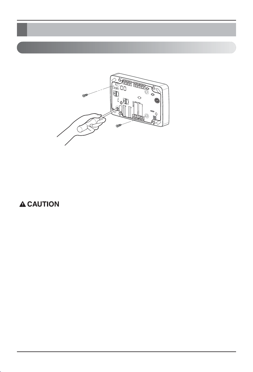
Installation Method
Installation inside of the indoor unit
① Loose 3 screws anchoring PCB and then separate PCB from the rear case
② Connect the connection wires according to the instructions. (Please refer to Setting and Using
Method)
③ Perform the switch setting according to switch setting method. (Please refer to Setting and Using
Method)
④ Fix PCB on suitable space inside of the indoor unit.
1. Install the product on flat surface and screw at least 2 places. Otherwise the Dry contact may not
be anchored properly.
2. Do not screw too tightly. It may cause deformation of the case.
3. Do not deform the case at random. It may cause malfunction of the Dry contact.
 Loading...