

Page 1

OWNER’S MANUAL
Please read this manual carefully before operating
your set and retain it for future reference.
P/NO : MFL62077702
www.lge.com
TYPE : AC Smart II
Advanced Control Smart
Page 2

2
AC Smart
AC Smart
TABLE OF CONTENTS
1. AC SMART II Introduction...............................1-1
AC Smart characteristics ...............................................................................................1-1
AC Smart exterior............................................................................................................1-3
AC Smart components ...................................................................................................1-5
AC Smart product specifications ..................................................................................1-6
2. AC Smart II Installation ...................................2-1
Before installing AC Smart.............................................................................................2-2
Setting unit address........................................................................................................2-3
• Setting address with wired remote controller ...............................................................2-4
• Setting address with wireless remote controller...........................................................2-5
Setting PI485 and connecting line.................................................................................2-7
• Setting PI485 DIP switch..............................................................................................2-7
• Connecting 2PIN connector .........................................................................................2-9
• Connecting RS485 line to PI485 ................................................................................2-11
Installing AC Smart and connecting line ....................................................................2-14
Logging in of the AC Smart..........................................................................................2-17
• Logging in as installation professional........................................................................2-18
• Logging in as administrator ........................................................................................2-19
• Logging in as general user.........................................................................................2-20
Registering the unit ......................................................................................................2-21
• Automatically registering the unit ...............................................................................2-21
• Directly registering the unit.........................................................................................2-25
Setting the emergency stop interlocking....................................................................2-29
Page 3

Installation/Owner's Manual
3
3. AC SMART MENU ...........................................3-1
Control/Monitoring menu ...............................................................................................3-1
• Zone information screen...............................................................................................3-2
• Group information screen.............................................................................................3-6
• Unit information screen ..............................................................................................3-10
Schedule menu..............................................................................................................3-18
• Schedule main screen................................................................................................3-19
• Edit weekly pattern screen .........................................................................................3-24
• Edit schedule detail screen ........................................................................................3-32
History menu .................................................................................................................3-40
• Usage view screen.....................................................................................................3-43
Auto control menu ........................................................................................................3-45
• Temperature limit operation .......................................................................................3-46
• Auto change over operation .......................................................................................3-49
• Time-limited running...................................................................................................3-52
Setting menu .................................................................................................................3-54
• Setting main screen....................................................................................................3-54
• Register unit screen ...................................................................................................3-57
Other setting menu .......................................................................................................3-59
• Version information ....................................................................................................3-60
• Password setting........................................................................................................3-61
• Language ...................................................................................................................3-62
• Time setting................................................................................................................3-63
• Screen adjustment .....................................................................................................3-64
• Screen saver ..............................................................................................................3-65
• Network ......................................................................................................................3-66
• E-mail setting..............................................................................................................3-69
• S/W upgrade ..............................................................................................................3-71
• DB management ........................................................................................................3-72
Web server function......................................................................................................3-73
Page 4

AC Smart
4
Logging in of the AC Smart............................................................................................4-1
• Logging in as installation professional..........................................................................4-2
• Logging in as administrator ..........................................................................................4-3
• Logging in as general user...........................................................................................4-4
Control/Monitoring..........................................................................................................4-5
• Controlling the unit .......................................................................................................4-6
• Controlling the unit in detail........................................................................................4-10
Schedule ........................................................................................................................4-15
• Managing schedule group..........................................................................................4-15
• Applying schedule ......................................................................................................4-25
• Creating schedule pattern ..........................................................................................4-29
• Directly editing the schedule .....................................................................................4-47
History............................................................................................................................4-55
• Browsing history.........................................................................................................4-55
• Browsing specific history............................................................................................4-56
• Usage view.................................................................................................................4-59
Auto control...................................................................................................................4-63
• Setting temperature limit operation ............................................................................4-66
• Managing temperature limit operation group..............................................................4-69
• Setting auto change over operation ...........................................................................4-79
• Managing auto change over operation group.............................................................4-82
• Setting the time-limited running..................................................................................4-92
• Managing the time-limited running group...................................................................4-95
Setting..........................................................................................................................4-106
• Registering unit ........................................................................................................4-106
• Managing zone.........................................................................................................4-112
• Managing group .......................................................................................................4-121
• Managing the unit.....................................................................................................4-133
4. OPERATING AC SMART..................................4-1
Page 5

Installation/Owner's Manual
5
Environment setting ...................................................................................................4-145
• Checking the S/W version information .....................................................................4-146
• Setting the password................................................................................................4-147
• Setting the language by country...............................................................................4-150
• Setting the time ........................................................................................................4-153
• Calibrating the screen ..............................................................................................4-154
• Setting the screen saver...........................................................................................4-157
• Setting the network information................................................................................4-158
• Setting the E-mail.....................................................................................................4-163
• S/W upgrade ............................................................................................................4-167
• Backing up and restoring the database....................................................................4-170
(a) For a Class A digital device or peripheral, the instructions furnished the user shall include the
following or similar statement, placed in a prominent location in the text of the manual:
NOTE: This equipment has been tested and found to comply with the limits for a Class A digital device,
pursuant to Part 15 of the FCC Rules. These limits are designed to provide reasonable
protection against harmful interference when the equipment is operated in a commercial
environment. This equipment generates, use, and can radiate radio frequency energy and, if
not installed and used in accordance with the instruction manual, may cause harmful
interference to radio communications.
Operation of this equipment in a residential area is likely to cause harmful interference in which
case the user will be required to correct the interference at his own expense.
Page 6
Safety Precautions
AC Smart
6
Safety Precautions
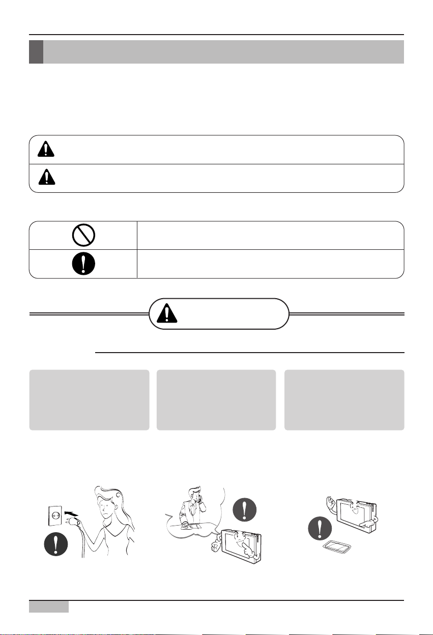
Do not operate or stop
the unit by inserting or
pulling out the power
plug.
• It will cause electric shock
or fire due to heat
generation.
Ask for Product
equipment at the service
center or establishment
certainly at the specialty
store.
• It can cause an accident,
electric shock, explosion or
injury.
Use standard parts.
• Use of non standard parts
can cause electric shock,
explosion, injury,
breakdown.
■ Operation
To prevent injury to the user or other people and property damage, the following instructions
must be followed.
■ Incorrect operation due to ignoring instruction will cause harm or damage. The seriousness is
classified by the following indications.
■ Meanings of symbols used in this manual are as shown below.
WARNING
CAUTION
This symbol indicates the possibility of death or serious injury.
This symbol indicates the possibility of injury or damage.
Be sure not to do.
Be sure to follow the instruction.
WARNING
Page 7
Safety Precautions
Installation/Owner's Manual
7
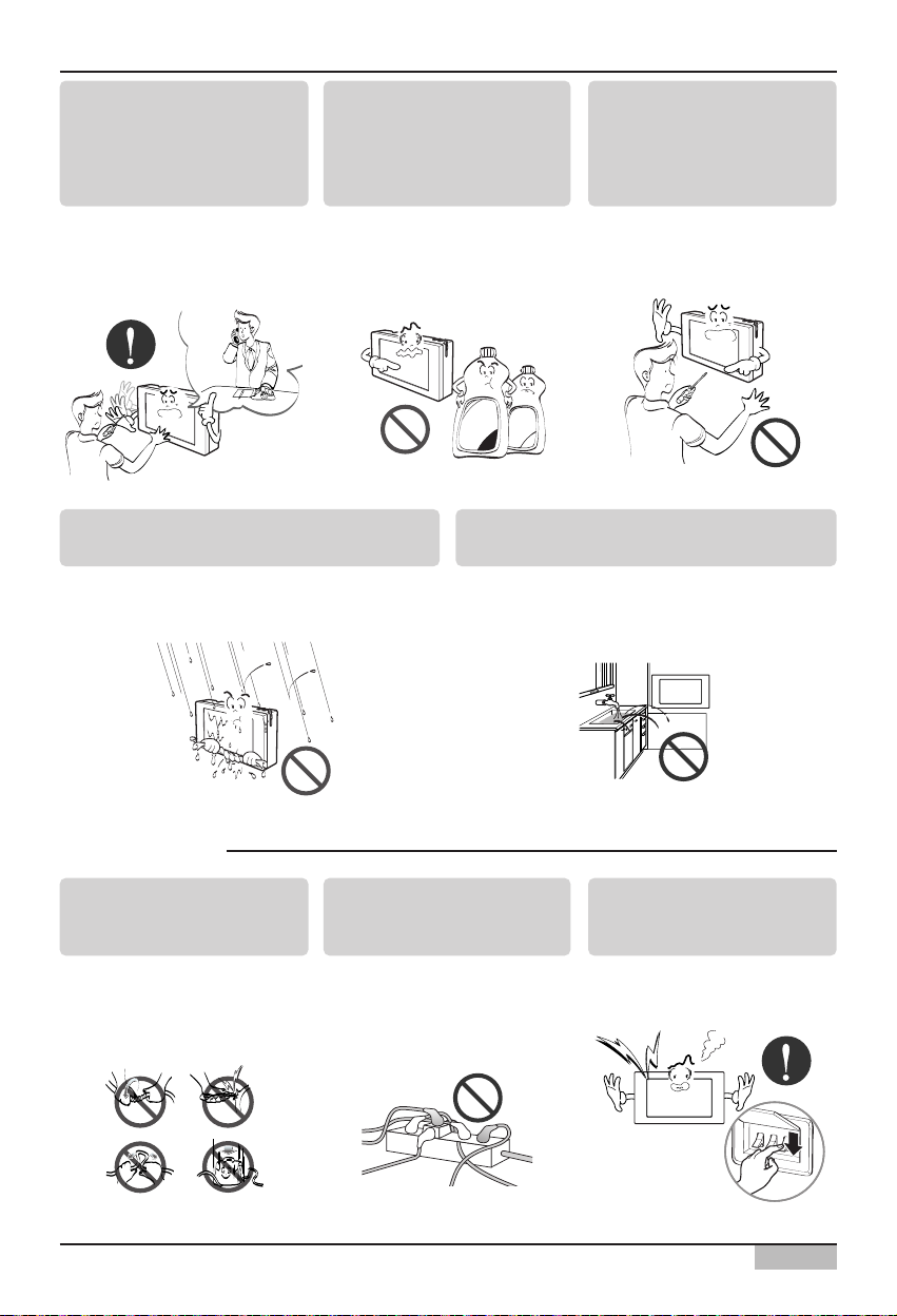
If water enters the product, turn the power
switch of the main body of appliance off.
• After taking the power-plug out from the socket,
contact the service center.
Keep the product away from the places
which can have moisture.
• Water may enter the unit and degrade the
insulation. It may cause an electric shock.
While re-installing the
established product, notify
the service center or
establishment specialty
store.
• It can cause an accident,
electric shock, explosion,
injury.shock.
Do not use the power cord
near Flammable gas or
combustibles, such as
gasoline, benzene, thinner,
etc.
• It may cause an explosion or
fire.
Do not disjoint randomly or
repair and remodel the
product.
• It may cause fire and electric
shock
■ During usage
Do not change or extend the
conductor at random.
• It can cause fire and electric
shock.
Do not use concert with in
the octopus-like legs way.
• It can cause fire and electric
shock
Unplug the unit if strange
sounds, smell, or smoke
comes from it.
• It may cause fire and electric
shock accident.
Diluant
Cire
Page 8
Safety Precautions
AC Smart
8
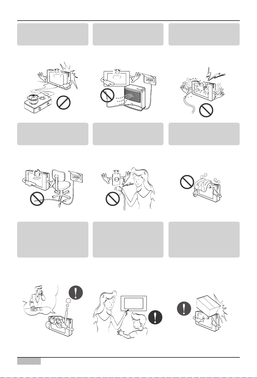
Do not put firearms near
product.
• It can cause fire.
Do not put an electric heater
or conductor near to the
product.
• It can cause fire and electric
shock.
Do not spill water inside
product.
• It can cause electric shock and
breakdown.
Do not place heavy goods
on wire.
• It can cause fire and electric
shock.
Hold the plug by the head of
the power plug when taking
it out.
• It may cause electric shock
and damage.
Do not place heavy goods
on product.
• It can cause product
breakdown.
That increase in case of
product was been flood
certainly in the service center
or establishment specialty
store commit .
• I am responsible for fire and
electric shock.
Protect the product from
handling by a children.
• It can cause accident and
product breakdown.
Do not apply shock to
product.
• I am responsible for breakdown in
case of shock to product.
Page 9
Safety Precautions
Installation/Owner's Manual
9
■ During usage
CAUTION
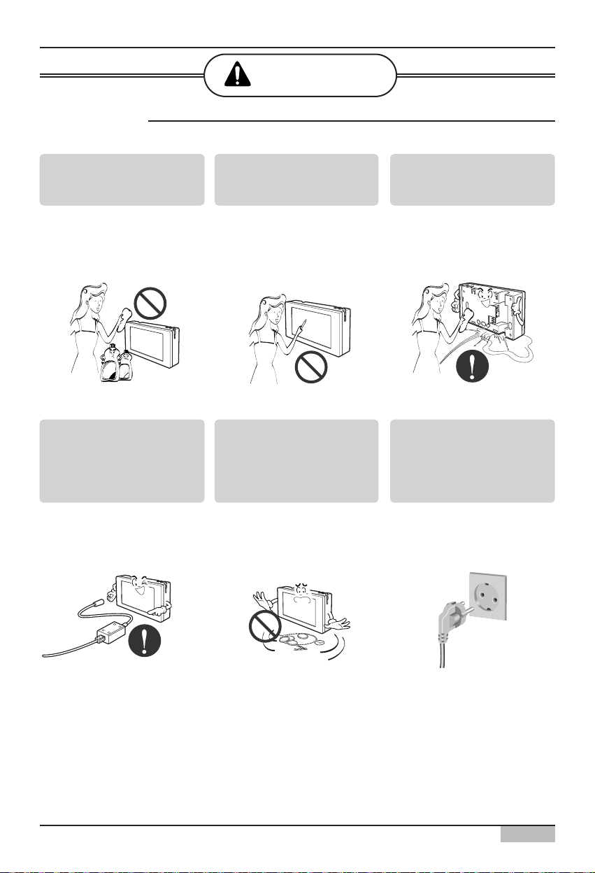
Clean by soft hands using a
cleaning material like a soft
cloth.
• It can result in fire and product
transformation.
Use touch screen with a pen
that product offers.
• Otherwise, there can be
breakdown and damage to the
product.
Do not place any live part on
the surface having water.
• It can cause product
breakdown.
C
ire
Diluant
Use recommended Adapter.
• Otherwise it can result in
product breakdown
Avoid contact to the metallic
goods such as necklace,
coin, key, a watch which
may touch the battery even
for a short-time.
• It may cause product
breakdown and injury.
Hold the plug by the head of
the power plug when taking
it out.
• It may cause electric shock
and damage.
Page 10

1. AC SMART II Introduction
AC Smart
1-1
AC SMART II Characteristics
AC Smart is the central controller that can manage maximum of 64 air conditioner indoor units within
one space individually or in integrated manner. AC Smart can monitor or control the operation of the
air conditioner and ventilator installed in each room of the building from one location, such as an
administrative office of the building.
The characteristics of AC Smart are as follows.
Individual and integrated operation & monitoring
AC Smart can control and monitor the following items by selecting the installed air conditioner by
individual unit, by group or all.
• Operating condition of the air conditioner
• Operating mode
• Fan level
• Wind direction
• Lock
• Set temperature
Therefore, the manager can control everything just with AC Smart (Central control) from the
administrative office of the building where the air conditioners are installed.
Group management
AC Smart can manage the installed air conditioners by zone and group. When you use the zone or
group setting, you can classify the air conditioner by type, location etc. Through these functions, you
can conveniently control the air conditioner and by assigning each name to the set group, you can
manage the groups intuitively.
Reduced administrative cost
Because you can use AC SMART II to control all units, you can administer all the units with only one
administrator. Also by using the schedule function of AC SMART II, the administrator can operate the
units automatically without having to be on site.
Convenient GUI
AC SMART II provides intuitive pictogram and simple interface for user to easily use the functions.
Through the easy to use interfaces, the user can conveniently control the units without any separate
training.
1. AC SMART II Introduction
Page 11

1. AC SMART II Introduction
Installation/Owner's Manual
1-2
Managing the automatic schedule operation & Saving the energy
The AC Smart can automatically run the air conditioner by setting the schedule.
When you register the schedule for a specific period by this schedule function, the\ unnecessary
operation of the air conditioner can be reduced and the energy can be efficiently saved. These
functions can efficiently performed by operating with a specific schedule such as school.
Various automatic control functions
The AC Smart offers various automatic control functions such as automatically switched running,
temperature limited running and time limited running as well as schedule. When the administrator sets
and executes these functions, various control functions such as maintaining a specific temperature
and limiting the air operation time can be automatically executed and managed by the AC Smart.
Protecting the system by the backup
The AC Smart offers the system information backup function for protecting the system from power
failure and other accidents, by which the stability of the system can be improved and the system can
be easily recovered from the accident.
Upgrading the software to the recent version
The AC Smart offers the function to upgrade the software to the recent version, by which the AC
Smart can be stably operated and a new function can be added.
Web server
The AC Smart offers the web server function to control the air conditioner by remotely accessing the
AC Smart via the network. The administrator can use the web server function to control the air
conditioner at the place other than the location where the AC Smart is installed.
E-mail notification
The AC Smart offers the function to notify the administrator of the critical error occurred during the
operation via the e-mail, by which the administrator can monitor the occurred error.
Extended interconnection
The AC Smart offers the extended interconnection function to control the air conditioner by
interconnecting with other devices. Basically, one AC Smart can control 64 air conditioners at
maximum. But, it can control 128 air conditioners at maximum when using the extended
interconnection function.
Page 12
1. AC SMART II Introduction
AC Smart
1-3
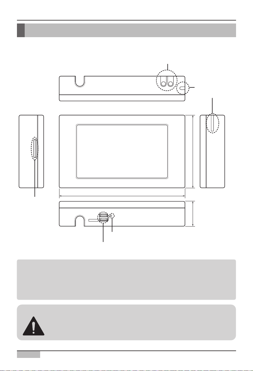
AC Smart is composed in the following shape.
AC SMART II exterior
Note: Using the external button to compensate the screen
The screen compensation function can be executed by pressing the keyboard button at the top of
the AC Smart and then the backlight button.
When it is hard to execute the screen compensation function by the touch screen, you can use this
method.
Caution: USB Port and Option card slot
USB port is only for SVC and development, therefore USB port is not available to
general users.
Option card slot is reserved for the future model.
Backlight button and keyboard button
Control panel
Stylus pen and
stylus pen holder
124mm
217mm
Option card slot
(reserved)
40mm
RESET BUTTON
USB PORT (only for SVC & Spare)
Page 13

1. AC SMART II Introduction
Installation/Owner's Manual
1-4
Backlight button
This is the button to turn on and off the LCD backlight of AC Smart. When you do not use AC Smart II
for a long period of time, it is good to turn off the backlight to extend the life of the LCD backlight.
Keyboard button
This is the button to display or hide the keyboard on the screen so that the user can enter the
characters.
Reset button
This is the button to reset AC Smart II when AC Smart II cannot be controlled from an error.
USB port (For service & Spare)
There are two types of USB ports.
Based on the bottom of the AC SMART II, the USB port (A Type) located on the left side is the USB
port to connect the USB memory to update the software or back up the data. This port supports USB
version 1.0.
The USB port (B Type) located on the right side is the USB port to connect the PC. This port supports
USB version 2.0.
Optional card slot (For adding optional function)
In the optional card slot, you can insert the optional card provided for the optional function of AC
SMART II.
Information: Optional function of AC SMART II
AC SMART II provides the following optional functions.
• Power display function: This shows the information of power consumption connected to the power
meter.
• Web schedule function: You can use the schedule function of AC SMART II by connecting to AC
SMART II remotely through the web.
You can purchase the optional function additionally and it is provided in card format.
Page 14
1. AC SMART II Introduction
AC Smart
1-5
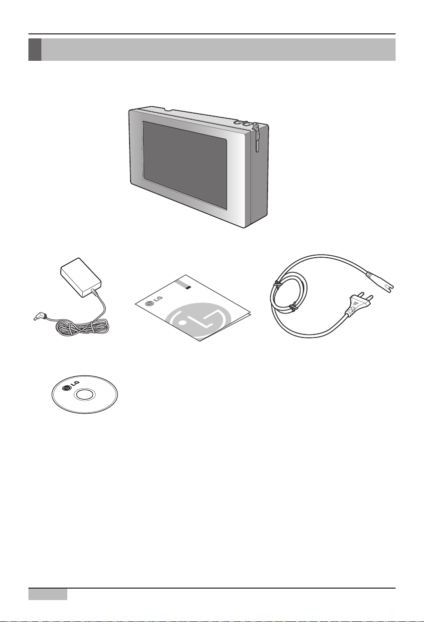
AC Smart II components
The components of AC Smart are as follows inside the box. Open the box of AC Smart and check
whether all components are included.
LG
AC Smart II
Power adapter
Manual CD
Quick Guide Power cord
Page 15
1. AC SMART II Introduction
Installation/Owner's Manual
1-6
AC Smart II product specifications
The product specifications of AC Smart are as follows.
Item Specifications
CPU
Memory
Boot ROM & Storage
LCD
Speaker
Button Key
DI
Power
Touch Screen
UART
USB
OS
MP2530F(or MP2531F)
- Dual CPU[ARM926E/360MHz + ARM946E/300MHz
128MB [DDR 64MB(A Bank) + DDR 64MB(B Bank)]
512MB (NAND Flash)
SD Card (support SDHC 8GB) (For optional card)
7.0” WVGA (800*480) TFT LCD
AST-01508MR-R
Display S/W(x1), Software Key S/W(x1)
S/W Input (For Fire-sensor)
DC 12V/1A
4 Wire, Touch Controller built-In.
RS-485 1Port
USB1.1 Host 2Port(For service)
USB2.0 Device 1Port (For development)
Windows CE 5.0 Core License
Page 16

2. AC Smart II Installation
AC Smart
2-1
2. AC Smart II Installation
This chapter describes the installation method to use AC Smart II.
To use AC Smart, you must construct an environment where AC Smart can communicate with the unit
(Indoor unit, ventilator, On/Off, AWHP) and register the indoor units.
To use AC Smart, you must execute the installation in the following order.
STEP 1.
Check environment before installing AC Smart Before installing
AC Smart, you must check the network among AC Smart II, outdoor
unit and unit.
STEP 2. Set unit address
Assign a unique address to the unit connected to AC Smart.
STEP 3. Set PI485
Install one PI485 for each outdoor unit, and set the DIP
switch.
STEP 4. Connect PI485 and AC Smart
Connect the PI485 and AC Smart through the RS485 line.
STEP 5. Login and register unit
Login to AC Smart and register the unit which the address
has been assigned to.
Caution: AC Smart installation
Installation of AC Smart requires special technology. Therefore,
The installation detail mentioned in this chapter must be executed by an
installation technician with installation qualifications.
If you have any questions or requests related to installation, please
consult the service center or installers designated by our company.
Information: Multi V II series
Multi V II series does not require separate installation of PI485, and you can use this by connecting
"BUS A" and "BUS B" to "Internet A" and "Internet B" of AC Smart II and Main PCB of outdoor unit.
Page 17
2. AC Smart II Installation
Installation/Owner's Manual
2-2
Before installing AC SMART II
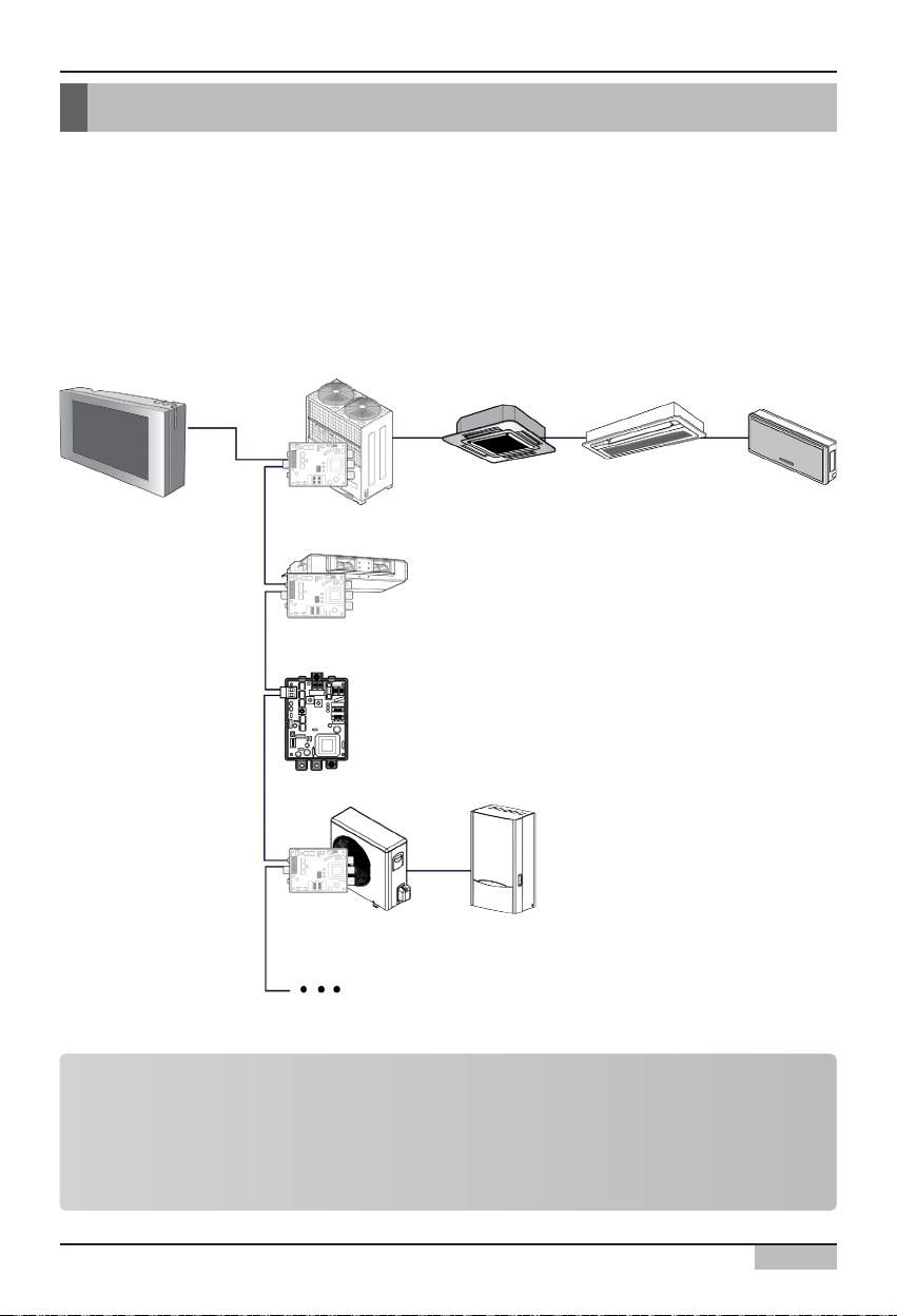
A single AC Smart can connect 64 units (indoor unit, ventilator, On/Off, AWHP) at maximum. It can
also connect 128 units via the extension kit (PQCSE440U0).
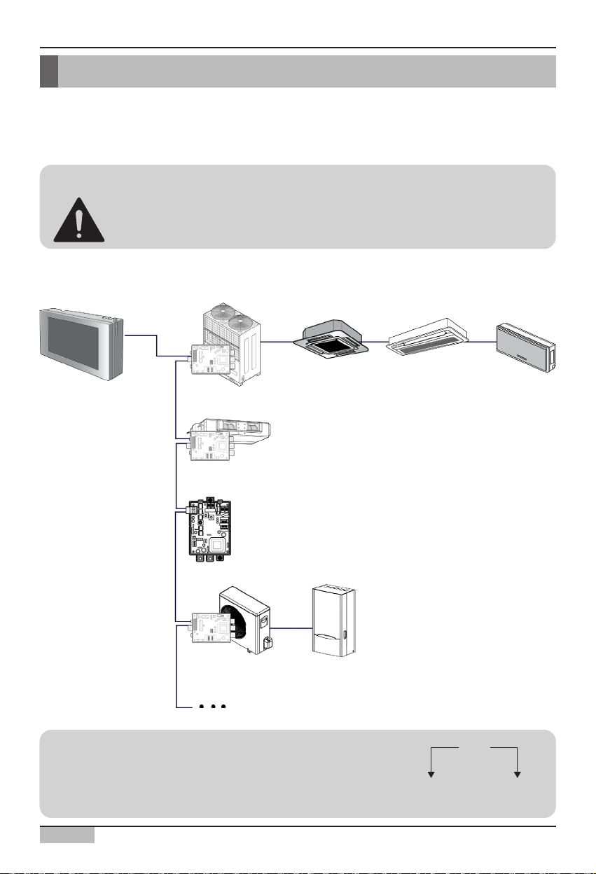
The following is an example of configuration of the AC SMART II and units. AC SMART II is
connected to PI485, and the units communicate the information mutually through RS485
communication. PI485 is connected to the devices for AC SMART II to control.
Information: Maximum permitted communication length and
specification
The maximum permitted communication length that LG Electronics guarantee is 1,000m. In other
words, the unit installed the farthest from AC SMART II must be installed within 1,000m distance.
It is recommended to use the communication cable of 0.75mm
2
(Shield) or above.
AC SMART II
PI485
PI485
PI485
Ventilator
On/Off unit
AWHP Outdoor unit
AWHP Indoor unit
Air conditioner
outdoor unit
Indoor unit 1 Indoor unit 2 Indoor unit 3
Page 18
2. AC Smart II Installation
AC Smart
2-3
Setting unit address
First, you must assign the address to each unit so that the address of each unit (Indoor unit, ventilator,
On/Off, AWHP) is not duplicated by considering the overall installation composition connected to AC
Smart II.
The address of the unit can be set in hexadecimal from 00 to FF.
The following is an example of assigning the address to the unit.
Caution: Setting address for indoor unit, ventilator, On/Off unit and
AWHP unit
You cannot set the same address for the indoor unit, ventilator On/Off unit and AWHP.
Make sure not to have duplicate addresses.
00
Group
number
Unit
number
00
Group
number
Unit
number
Reference: Setting address for device
When setting the address of a unit (Indoor unit, ventilator, On/Off
unit, AWHP unit), it is recommended to set the first digit as the
group number, and second as unit number for easy identification.
AC SMART II
PI485
PI485
PI485
Ventilator
On/Off unit
AWHP Outdoor unit
AWHP Indoor unit
Air conditioner
outdoor unit
Indoor unit 1 Indoor unit 2 Indoor unit 3
Page 19
2. AC Smart II Installation
Installation/Owner's Manual
2-4
When connecting and using the air conditioner with AC SMART II, you must set the address of each
indoor unit through the wired or wireless remote controller. You can set the address of the indoor unit
in the following order.
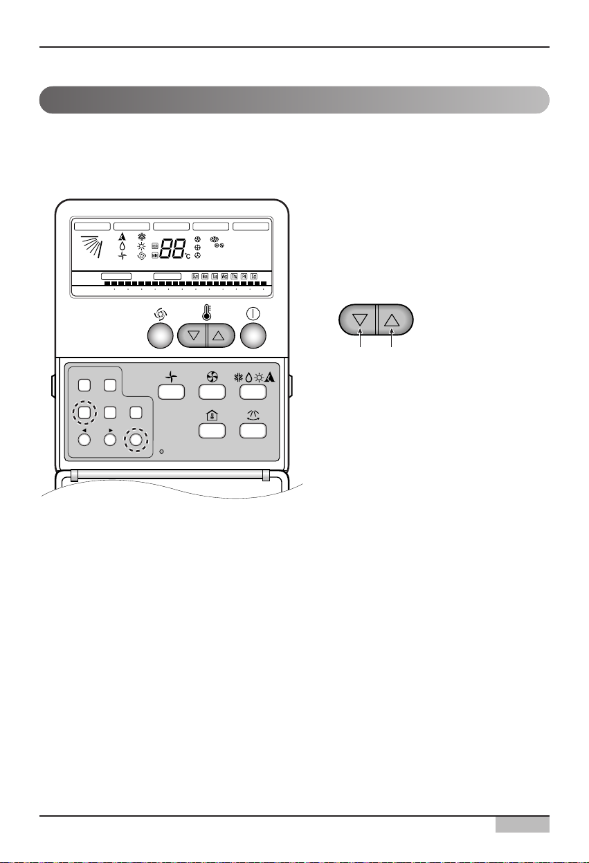
Setting address with wired remote controller
Setting address for indoor unit
Plasma
Timer Cancel
Program Week
Hour Min
Holiday
Set/Clr
RESET
ZONE
1234
Operation unit
Humidify
JET
AUTO
AUTO SWING OPERATION
FAN SPEED
Program set
SUB FUNCTION
SET TEMP
Room Temp
HI
MED
LO
Heater
Defrost
Filter
Preheat
Out door
Time
Timer
On
Set no. Time
Off
01 03 05 07 09 11 13 15 17 19 21 23
1. Press Week Program & Set/Clr keys at the
same time.
2. Set the indoor unit address using the
temperature controller.
Allowed Range: 00-FF
3. Complete the address setting to press the
week Program & Set/Clr keys at the same
time for 3 seconds.
Group No. Indoor Unit No.
Page 20
2. AC Smart II Installation
AC Smart
2-5
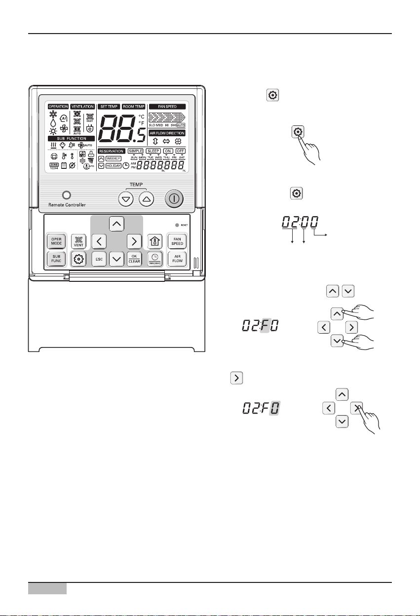
1. Press the button for 4 seconds to enter
the installer setting mode until timer segment
display "01:01".
2. Repeat pressing button to select
Function code 02.
Ex) Setting Address as 'F5'
3. Set Group No. by pressing button.
4. Move to Indoor No. setting option by pressing
button.
Setting the address with wired remote controller
Function Code Group No
Indoor No.
Page 21
2. AC Smart II Installation
Installation/Owner's Manual
2-6
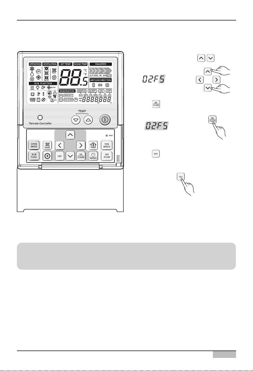
5. Set Indoor No. by pressing button.
6. Press button to save or release.
7. Press button to exit or system will
automatically exit after 25 seconds without
any input.
Reference: Exiting setting mode
If there is no button entry after the setting for 25 seconds, it will automatically exit the setting
mode.
Page 22
2. AC Smart II Installation
AC Smart
2-7
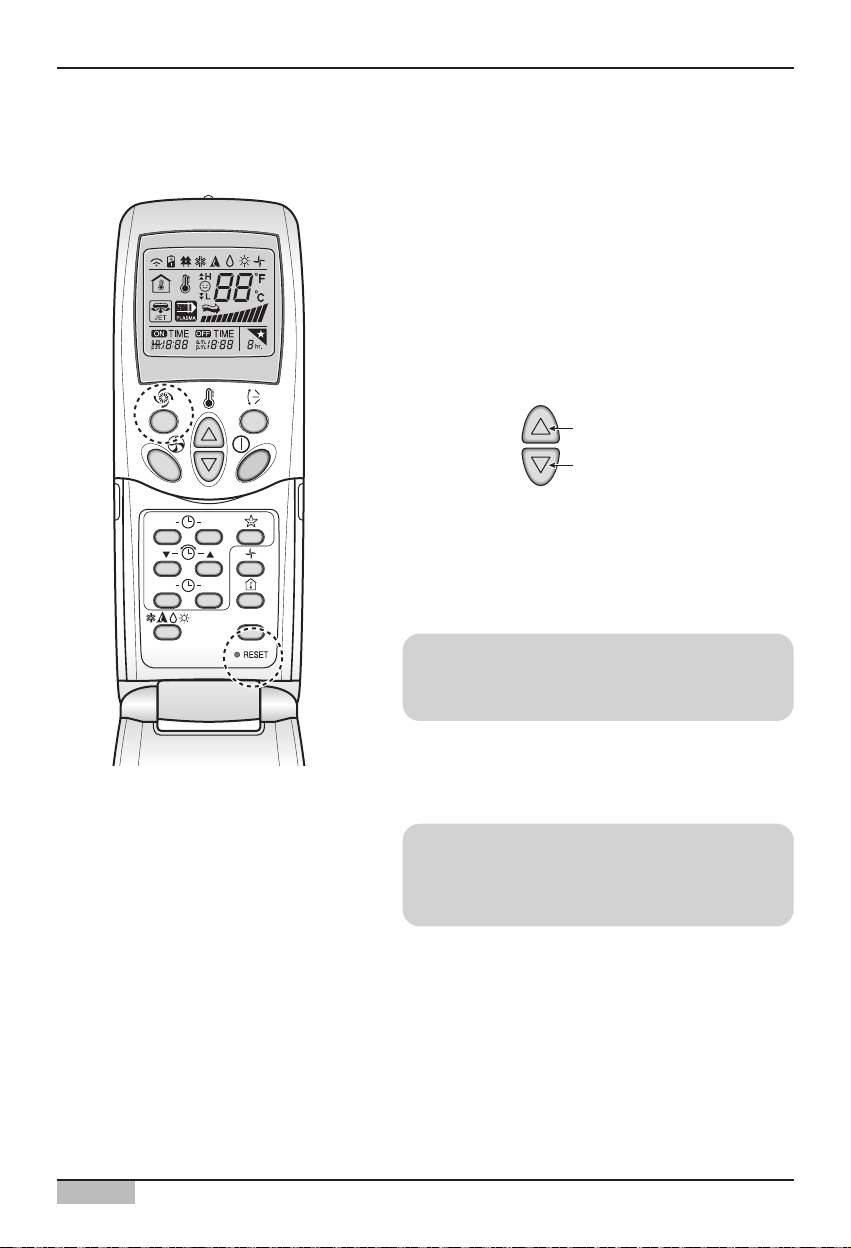
1. With the [Power Cool] button pressed, press the
[RESET] button. The [Power Cool] button must be
pressed for more than 3 seconds.
2. Use the [Temperature Adjustment] button to set
the address of the indoor unit.
3. After setting the address, press the [Operate/Stop]
button once toward the indoor unit.
4. When the set address is displayed on the indoor
unit, the address setting is complete.
5. When you reset the remote controller, it switches
from the address setting mode to general
operation mode.
Reference: Address display time and method
The address display time and method may differ
by the type of the indoor unit.
Reference: Type of remote controller
When using a different type of remote controller
from the one described above, refer to the user
manual of the applicable remote controller.
Group No.
Indoor unit No.
Temperature
adjustment
Setting address with wireless remote controller
ON OFF
SET
CANCEL
PLASMA
Page 23
2. AC Smart II Installation
Installation/Owner's Manual
2-8
ON OFF
SET
CANCEL
PLASMA
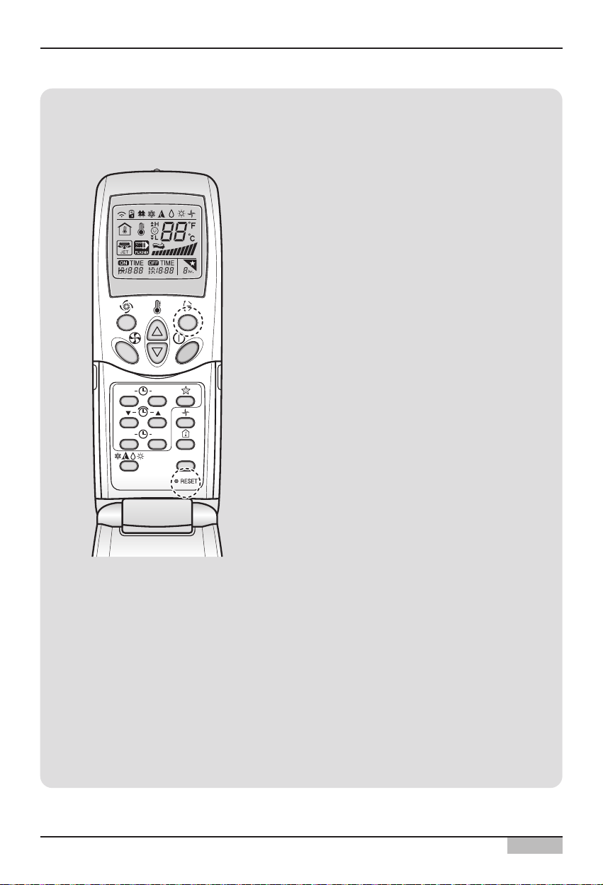
Information: Checking the set address
You can check the set address by using the
wireless remote controller. To check the set
address, proceed as follows.
1. With the [Wind Up/Down] button pressed,
press the [RESET] button. The [Wind
Up/Down] button must be pressed for more
than 3 seconds.
2. Press the [Operate/Stop] button once toward
the indoor unit. The set address will be shown
on the display part of the indoor unit. The
address display time and method can differ by
the type of indoor unit.
3. Reset the remote controller again to use it in
general operation mode.
Page 24
2. AC Smart II Installation
AC Smart
2-9
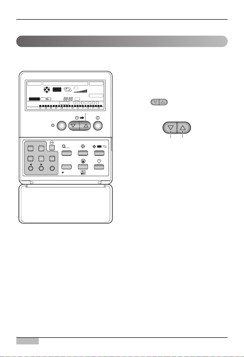
Setting ventilator unit address
1. To activate the address setting, press the
[Program] button and [Set/Clr] button
simultaneously for more than 3 seconds.
2. Use the button to set the address of
the ventilator. The range the address can be
set is 00~FF.
3. Press the [Program] button and [Set/Clr]
button for more than 3 seconds to complete
the address setting.
When connecting and using the ventilator with AC SMART II, you must set the address of each
ventilator using the wired remote controller. Set the address of the ventilator as follows.
Group�
number
Ventilator�
number
EXTERNAL VENTILATOR OPERATION
Linked Run
Dual Remote
Central Run Heat XCH Auto Normal Fan Speed
PLASMA
Timer
On Off
Set no. Timer
e-SAVER
fresh
Auto
Delay Time
Program set
Auto
Hi
Lo
Time
Filter
Sun
Mon
Tue Wed Thu
SUB FUNCTION
Heater Preheat
SHi
Defrost
Z O N E
1 2 3 4
Fri Sat
Humidify
Timer Cancel
Program Week
Hour Min
Holiday
Set/Clr
fresh
Plasma
TIME RESET
Auto
Page 25
2. AC Smart II Installation
Installation/Owner's Manual
2-10
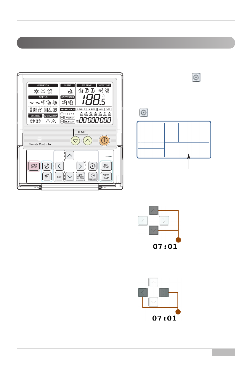
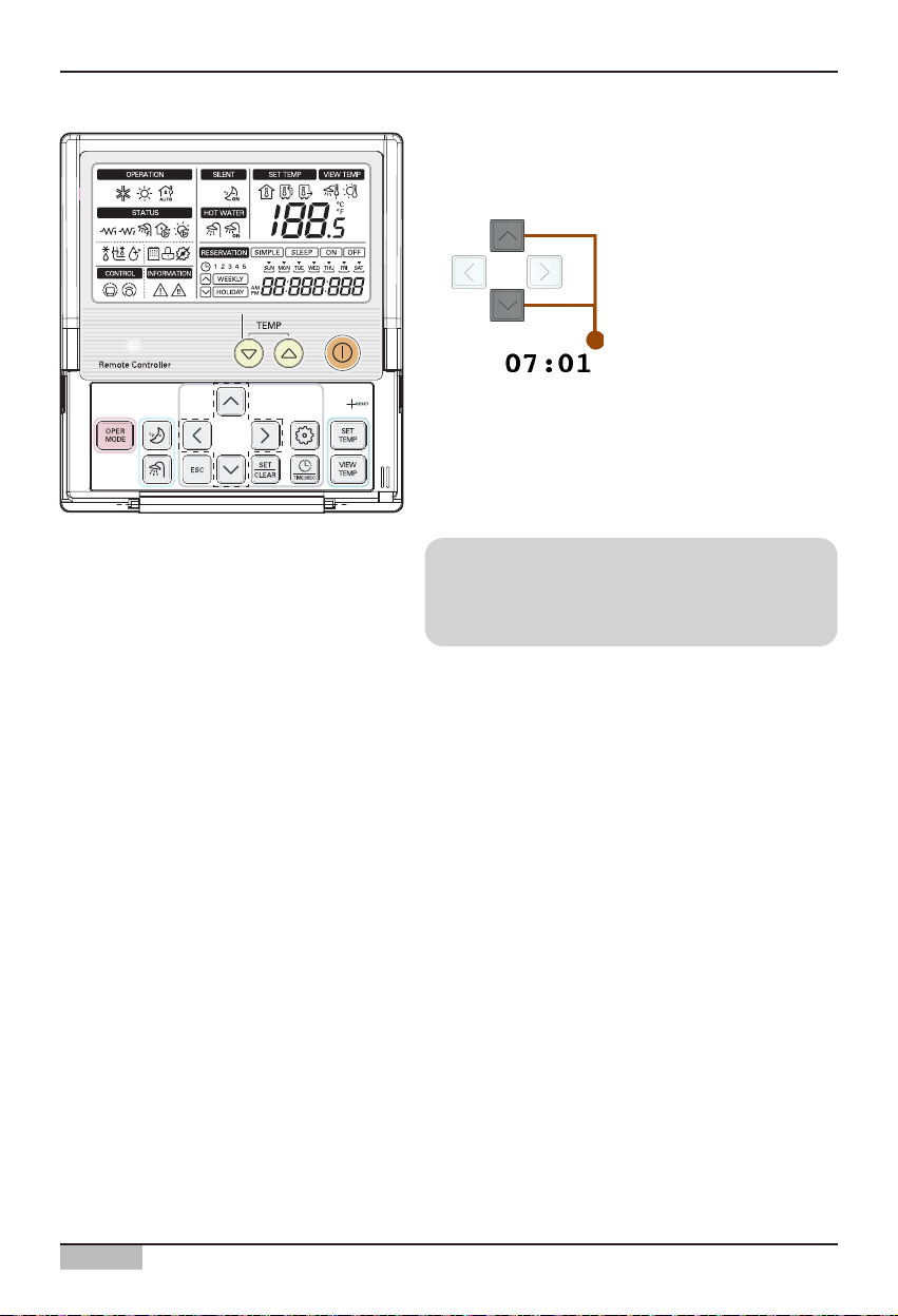
Setting AWHP unit address
1. Press the Setting button ( ) for more than
3 seconds until the number code is displayed
on the timer display block.
2. Continuously press the function setting button
( ) until the function code is set to 07.
3. Use the [Up], [Down] button to set the first
digit. First digit generally designates the
group number.
4. Use the [Left], [Right] button to move the
cursor to the last digit.
When connecting and using the AWHP unit with AC SMART II, you must set the address of the
AWHP unit using the wired remote controller. Set the address of the AWHP unit as follows.
0701
Function Code
Page 26
2. AC Smart II Installation
AC Smart
2-11
5. Use the [Up], [Down] button to set the last digit.
The last digit generally refers to the individual
AWHP unit number.
6. After setting the address, press the [SET/CLEAR]
button to complete the address setting.
7. Press the [ESC] button to exit the setting mode.
Reference: Exiting setting mode
If there is no button entry after the setting for 25
seconds, it will automatically exit the setting
mode.
Page 27
2. AC Smart II Installation
Installation/Owner's Manual
2-12
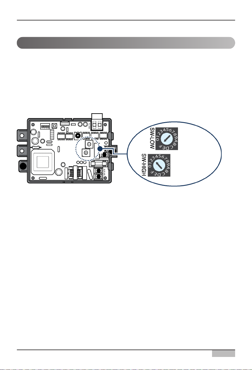
When connecting and using the On/Off unit (PNF-P14A0T) with AC SMART II, you must set the
address of the On/Off unit through the rotary switch.
On/Off unit has 2 rotary switches to set the address as shown in the below picture.
ʻSW-HIGHʼ rotary switch sets the group number and ʻSW-LOWʼ rotary switch sets number of each
On/Off unit.
The following pictures show an example of setting the address of On/Off unit to “3F”.
Setting On/Off unit address
Unit number
Group
number
Ex) "3F"
Page 28
2. AC Smart II Installation
AC Smart
2-13
Setting PI485 and connecting line
After setting the address of the unit, you must install PI485 and set the DIP switch. And then you must
connect the RS485 line to communication with AC Smart II.
First set the DIP switch of PI485. You can check the DIP switch of PI485 in the following location.
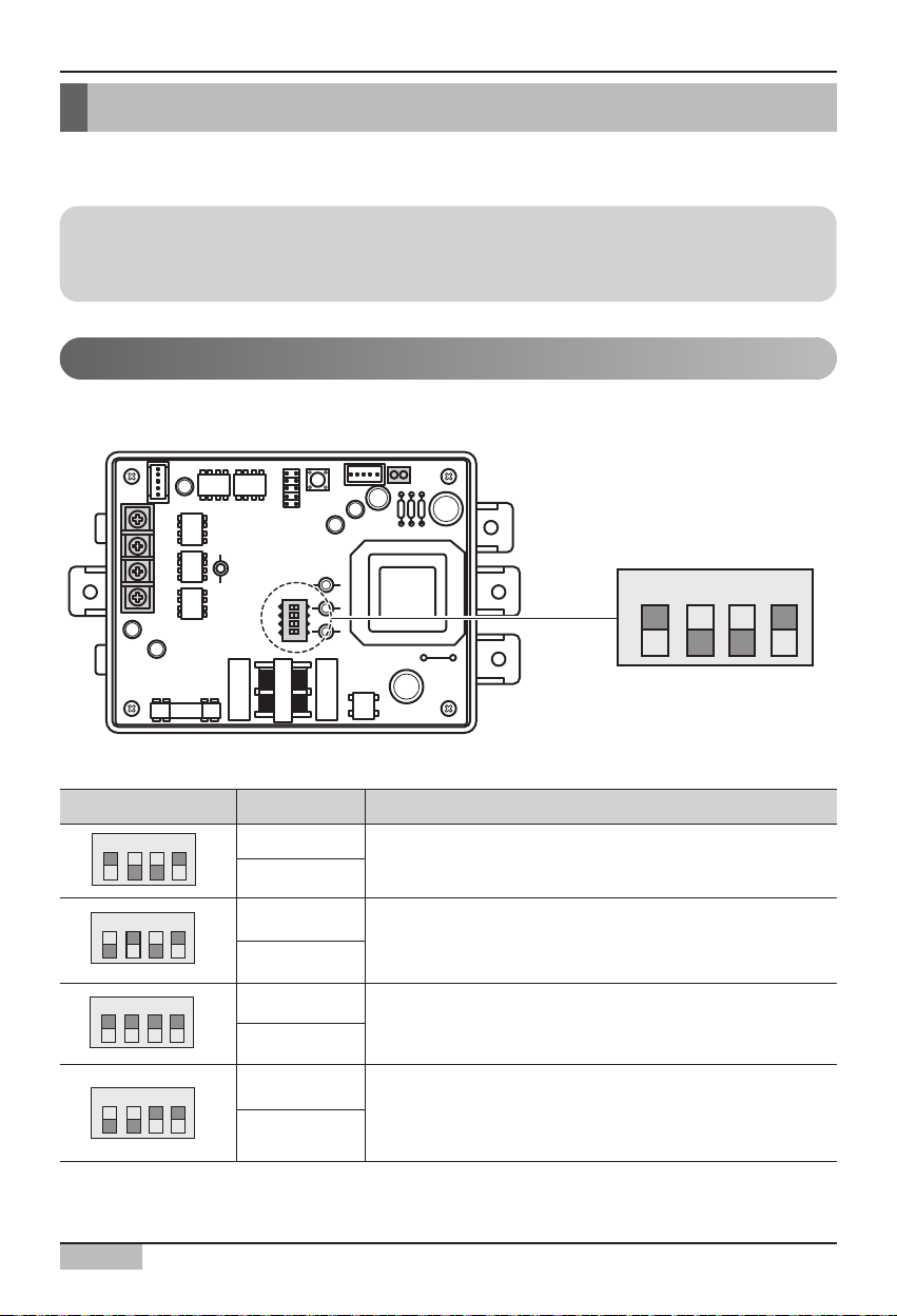
For the model composed of 4 DIP switches, it can be set as follows.
Set the DIP switch as follows depending on the type of outdoor unit PI485 is attached to.
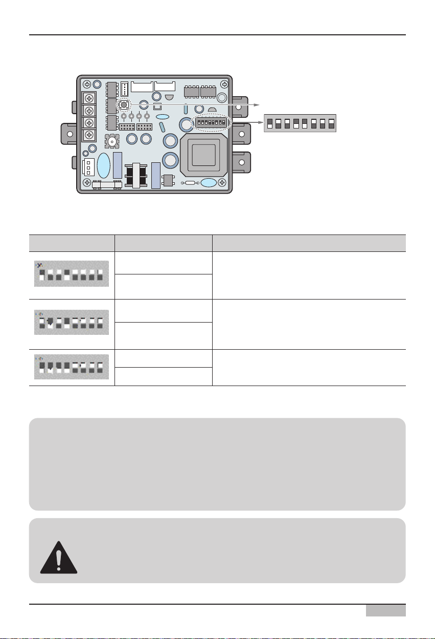
For model composed of 8 DIP switches, it can be set as follows.
Reference: PI485 installation
The installation of PI485 may differ by the product of the outdoor unit. Therefore, refer to PI485
manual or installation technology information to proceed.
Setting PI485 DIP switch
DIP switch Setting Product type
- Multi V product (Excluding CRUN, LRA product)
- MPS static speed product with common PCB applied
- MPS inverter product
- MPS static speed product without common PCB applied
- Multi V CRUN, LRA product
- Single indoor unit (When connected to PI485 for indoor unit,
model name PSNFP14A0 / PHNFP14A0)
- Ventilator (When connected to PI485 for ventilator, model
name PHNFP14A0)
O N K S D O 4 H
O N K S D O 4 H
O N K S D O 4 H
O N K S D O 4 H
ON: 1, 4
OFF: 2, 3
ON: 2, 4
OFF: 1, 3
ON: 1, 2, 3, 4
OFF: -
ON: 3, 4
OFF: 1, 2
ON
L1 2 3 4
KSDO4H
O N K S D O 4 H
Page 29
2. AC Smart II Installation
Installation/Owner's Manual
2-14
Reference: PCB part #
MPS static speed applied product with common PCB applied must have the PCB part # as shown
as follows.
• PCB P/NO. : 6871A20910A ~ Z
• PCB P/NO. : 6871A20917A ~ Z
• PCB P/NO. : 6871A20918A ~ Z
Caution: PI485 DIP switch setting
When the air conditioner selection switch setting is incorrect, the air conditioner can
malfunction.
Refer to PI485 (M) manual for detail installation method of PI485.
Set the DIP switch as follows depending on the type of outdoor unit PI485 is attached to.
After setting the DIP switch, you must always reset the PI485. Press the reset switch to reset PI485.
DIP switch Setting Product type
- Multi V product (Excluding CRUN, LRA product)
- MPS static speed product with common PCB
applied
- MPS inverter product
- MPS static speed product without common PCB
applied
- Multi V CRUN, LRA product
ON: 1, 4
OFF: 2, 3, 5, 6, 7, 8
ON: 2, 4
OFF: 1, 3, 5, 6, 7, 8
ON: 1, 2, 3, 4
OFF: 5, 6, 7, 8
Reset switch
L1 2 3 4
ON
KSDO4H
Page 30
2. AC Smart II Installation
AC Smart
2-15
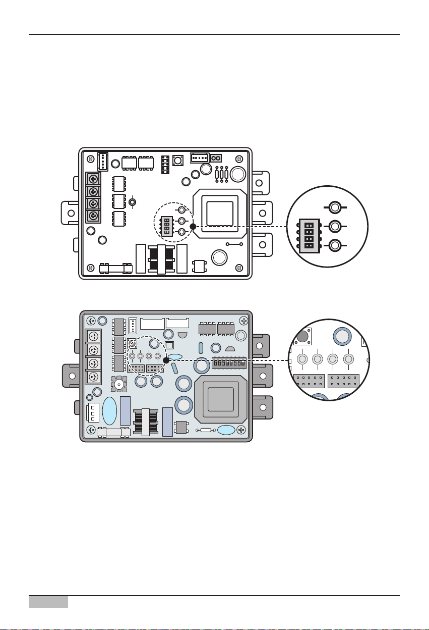
Information: Checking PI485 DIP switch setting
You can check whether the indoor unit address setting and the DIP switch setting of PI485 have been
set correctly as follows.
• LED01G will flash for as many as the connected number of indoor units.
• LED02G and LED03G will flash in switching back and forth. (When connecting LRA/CRUN
product, LED02G can blink more than LED03G).
When the LED is abnormal unlike the above description, recheck the address setting of the indoor unit
and DIP switch setting.
LED01G
LED02G
LED03G
LED03G
ON
L1 2 3 4
KSDO4H
KSDO4H
L1 2 3 4
ON
LED02G
ON
L1 2 3 4
KSDO4H
LED01G
Page 31

Installation/Owner's Manual
2-16
2. AC Smart II Installation
AC SMART II provides the lock function through the central control to disable individual control of
operating mode, fan level and temperature of the indoor unit. To use this lock function, you must
connect the 2PIN connector to the CN_DRY of PI485 or set DIP switch #5 to On depending on the
outdoor unit product type.
For PI485 with 8 DIP switches, set the DIP switch as follows depending on the type of outdoor unit on
which the PI485 is attached.
Setting individual lock function
CN_DRY
For PI485 with 4 DIP switches,
connect the 2PIN connector to
the CN_DRY terminal
For PI485 with 8 DIP switches,
set the #5 DIP switch to ON
DIP switch Setting Product type
- Multi V product (Excluding CRUN, LRA product)
- MPS static speed product with common PCB
applied
- MPS inverter product
- MPS static speed product without common PCB
applied
- Multi V CRUN, LRA product
ON: 1, 4, 5
OFF: 2, 3, 6, 7, 8
ON: 2, 4, 5
OFF: 1, 3, 6, 7, 8
ON: 1, 2, 3, 4, 5
OFF: 6, 7, 8
Reference: Set 2PIN connector and DIP switch #5 ON
The setting method can differ by PI485 number. 2PIN connector connection and DIP switch #5 ON
setting is the connector and DIP switch required for PI485 to set the function for the product without
the individual lock and temperature setting range within the product.
ON
L1 2 3 4
KSDO4H
L1 2 3 4
ON
KSDO4H
Page 32

AC Smart
2-17
2. AC Smart II Installation
The following picture shows an example of the central control method when the 2PIN connector is
connected to the CN_DRY terminal or when the DIP switch #5 is set to ON.
1) Through the central controller, such as AC Smart, you can command the 'Cool operation, 20°C
setting, high fan level, temperature lock' function. This command can be provided by the remote
controller.
2) But if the user changes the temperature to 25°C with the remote controller, the applicable command
is sent tot eh outdoor unit and the 25°C setting is displayed on the remote controller.
3) The outdoor unit receives the applicable command and sends it to PI485.
4) PI485 cancels this command and resends the prior central control command. And the remote
controller redisplays the temperature of 20°C sent through the central control command.
This time, this is an example when the 2PIN connector is not connected to CN_DRY terminal or when
the DIP switch #5 is not set to ON.
When you command the “Cool operation, 20°C setting, high fan level, temperature lock” function
through central control, the applicable command is transmitted to the remote controller. “HL (Hard
Lock)” message displaying the central control status is displayed on the remote controller. If the user
sets the temperature to 25°C, the remote controller blocks the userʼs command.
Multi V
AC Smart
ON
L1 2 3 4
KSDO4H
1) Cool/20°C/High/Temperature lock setting
2) Change temperature to 25°C
3) Cool/25°C/High
5) Cool/25°C/High
4) Cool/25°C/High
Multi V
AC Smart
ON
L1 2 3 4
KSDO4H
Cool/20°C/High/Temperature lock setting
'HL' message displayed on remote controller
User cannot operate the remote controller
Page 33

Installation/Owner's Manual
2-18
2. AC Smart II Installation
Connecting PI485 to RS485 Line
To connect PI485 and AC Smart, two RS485 lines must be connected to BUS_A and BUS_B of
PI485. Refer to the following figure to connect the RS485 line.
Reference: Connecting RS485 cable to PI485
The shape of PI485 can differ by the number. For details, refer to the installation manual provided
with the PI485 product.
BUS_A BUS_B
ON
10V CND
L1 2 3 4
KSDO4H
Page 34

AC Smart
2-19
2. AC Smart II Installation
The following figure is an example of several units of PI485 connected to AC Smart.
+100 GND BUS_A BUS_B
+100 GND BUS_A BUS_B
+100 GND BUS_A BUS_B
BUS_A
BUS_B
AC Smart II
ON
L1 2 3 4
KSDO4H ON
L1 2 3 4
KSDO4H ON
L1 2 3 4
KSDO4H
Page 35

Installation/Owner's Manual
2-20
2. AC Smart II Installation
Information: RS485 connection of AC SMART II
Maximum of 64 indoor units can be connected to one AC SMART II, and when the expansion kit
is installed, maximum of 128 indoor units can be connected. If there are many number of outdoor
units to connect, the outdoor unit must be connected in BUS format. If not, AC SMART II can
malfunction.
The left picture shows the correct and
incorrect example of RS485 communication
connection to of AC SMART II.
The upper picture shows the correct example
of RS485 connection to outdoor unit with AC
SMART II in BUS format.
The bottom picture shows the incorrect
example of RS485 connection to outdoor unit
with AC SMART II in STAR format.
<Correct example: RS485 BUS format connection>
<Incorrect example: RS485 STAR format connection>
Page 36

AC Smart
2-21
2. AC Smart II Installation
+
S19
Rotary
Switch
DIP
Switch
ON
L1 2 3 4
KSDO4H
ON
L1 2 3 4
KSDO4H
+100 GND BUS_A BUS_B
RS485
CN-POWER
GND
CN-COM A
S4
S3
S12
S16
TX1
LED4
LED8
LED12
LED11
LED16
LED15
PWB:6870A10001A
ASM:6711A20005E
LED7
LED3
L
+
+
+
+
+
+
+
+
+
S15
S18
S19
S15
S11
S2
LED2
S5
S9
+
+
+
S1
IC1P
LED5
LED9
LED13
LED17
LED10
LED14
S14
+
S6
S10
CN-POWER
CN-COM B
ON
L1 2 3 4
KSDO4H
C
D
GND
BUS_A
BUS_B
Information: Connection setting when using simple central
controller with AC Smart
You can use a simple central controller with AC Smart. When you want to use a simple central
controller with AC Smart, connect the simple central controller in the order shown as follows.
1. Connect the BUS-A and BUS-B port of PI485 to the A and B terminal of the simple central
controller using the RS485 communication cable.
2. Set the rotary switch of the simple central controller to align with the group number of the
indoor unit to control. For example, when you want to control the indoor units with the address
of 00~ 0F, set the rotary switch to 0.
3. Set the DIP switch No. 1 of the simple central controller to OFF (Slave) and No. 2 to ON (LGAP
use mode).
Reference: Check V-net Label
Check the V-net Lbel on the right side of the case of the simple central controller. AC Smart II
can be simultaneously connected only to the product with the label.
You must connect the VCC and GND terminal of the simple central controller to connection of
PI485 or to a separate adapter. For more details, refer to the manual of the simple central
Page 37

Installation/Owner's Manual
2-22
2. AC Smart II Installation
Installing AC SMART II and connecting line
After setting PI485, install AC Smart and connect the RS485 line for communication with PI485.
또한 웹 서버, 이메일 통보 기능을 사용하거나 SVCNet과 통신하고자 할 경우에는 UTP 케이블을 연결해
야 합니다.
To install AC Smart and connect the line, proceed as follows.
1. Decide the space to install AC Smart. In order for AC Smart to be installed on the wall, there must
be a RS485 line near by.
2. Fixate the rear panel of AC Smart on the wall top of the RS485 line. Fixate the panel using a driver.
You can fixate the panel as shown below, depending on the installation location.
Reference: AC Smart II installation
AC Smart is designed to be basically installed on the wall. Here, we explain the method of installing
AC Smart on the wall as the example.
Page 38

AC Smart
2-23
2. AC Smart II Installation
3. Pull out the RS485 cable through the hole of the rear panel and connect it to the socket.
Use the ʻ-ʻ driver to connect the two RS485 communication cable as follows.
4. Connect the RS485 socket to the RS485 port located on the rear side of the AC SMART II main
unit.
RS485 - RX (BUS-B)
RS485 - TX (BUS-A)
BUS-B
BUS-A
Caution: RS485 communication cable connection
When connecting the RS485 communication cable, be careful not to mix the polarities
of the two lines
Page 39

Installation/Owner's Manual
2-24
2. AC Smart II Installation
5. To use the network related function provided by AC SMART II (Emaion transmission, SVCNet
connection), the UTP cable must be connected.
Connect the UTP cable that can be connected to the Internet on the rear side of the main unit of
AC SMART II to the LAN port.
6. Connect the power adapter to the power terminal located at the rear side of the main unit of AC
Smart.
Page 40

AC Smart
2-25
7. Assemble the main unit of AC Smart on the rear penal installed on the wall. After hanging the top
holes of the top of the main unit to the top of the rear panel, push forward and slide in the bottom of
the main unit.
8. Connect the power cord of the power adapter to the power outlet.
Page 41

Installation/Owner's Manual
2-26
2. AC Smart II Installation
Here, the installation personnel with the authority must log in to AC SMART II for the setting required
for the installation process of AC SMART II. To log in with the installation expert authority, proceed as
follows.
1. When you press and hold the top left of the log-in screen for 5 seconds, the password screen is
displayed to enter the password.
Logging in of AC SMART II
When the power is applied to the AC Smart, the AC Smart automatically operates. When the AC
Smart II operates, the LG logo screen is initially displayed and then chanted to the login screen.
The AC Smart II can be logged in with three method such as professional, administrator and general
user as follows:
Log in for
installation
professional
Log in for
administrator
Pressing and
holding here for
5 seconds to
display the input
screen
Log in for
general user
Page 42

AC Smart
2-27
2. AC Smart II Installation
2. The password is ʻdigital21ʼ which cannot be changed. When you correctly enter the password and
press [OK] button, you are logged in and can set all functions of the AC Smart.
3. When you log in, the following menu screen will be displayed and you can use all functions of AC
SMART II.
After enter 'digital21',
press [OK] button
Page 43

Installation/Owner's Manual
2-28
2. AC Smart II Installation
After connecting PI485 to AC Smart, you must operate AC Smart to register the unit the address has
been set to.
You can register the unit in 2 methods to AC Smart.
• Automatically registering the unit
• Directly registering the unit
You can automatically search and register the unit connected to AC Smart. To automatically register
the unit, proceed in the following order.
1. After logging in with installation professional to AC SMART II, select the ʻDevice management ʻ
menu from the menu.
Registering the unit
Note: Login right for registering a unit
In order to register a unit to the AC Smart, you should log in as installation professional. This menu is
not displayed on the screen when logging in as administrator or general user.
Automatically registering the unit
Press [System] button
Page 44

AC Smart
2-29
2. AC Smart II Installation
2. When you select the ʻDevice management menu, the following screen will be displayed. Press the
[Device registration] button located on the bottom right side.
3. ʻDevice registrationʼ screen will be displayed. When you press the [Auto set] button, the
ʻConfirmationʼ screen to check the execution of auto setting will be displayed. Press the [Yes]
button.
Click on [Unit] button
After clicking [Auto],
when the screen is
displayed click on [Yes]
button
Page 45

Installation/Owner's Manual
2-30
2. AC Smart II Installation
4. The process to search for and register the indoor unit and the ventilator connected to the AC Smart
II proceeds. When this process is finished, the registered unit is added and displayed at the table
located at the bottom of the screen.
5. Temporarily store the searched unit. When you press [OK] button, the ʻConfirmʼ screen for
confirming saving is displayed. When you press ʻYesʼ button, saving is done and it returns to the
previous screen.
After the device search,
the result will be
displayed.
To apply to system
click on [OK] button,
'When the
'Information' screen
is displayed click on
[Yes] button
Page 46

AC Smart
2-31
2. AC Smart II Installation
6. Finally, the temporarily saved unit setting should be registered to the system.
When [Save] button is pressed, ʻInformationʼ screen to check whether to apply the current setting to
the system is displayed. Press [Yes] button.
7. Current setting will be applied to the system and the message saying that the setting has been
saved will be displayed. Click on the [OK] button to complete the registration.
To apply to system, click on [Save]
button click on [Yes] button
When it is saved, click on [OK] button
Reference: Change information of registered unit
When you want to change the information of the registered unit such as name, or form a group with
the units, refer to the ʻSettingʼ section on page 4-106.
Page 47

Installation/Owner's Manual
2-32
2. AC Smart II Installation
Directly registering the unit
You can directly register the unit connected to AC Smart. To register the unit, proceed in the order as
follows.
1. After logging in as installation professional to AC SMART II, select the ʻDevice managementʼ menu
from the menu.
2. When you select the ʻDevice managementʼ menu, the following screen will be displayed. Press the
[Device registration] button at the bottom right side.
Press the [Device
management button
Click on [Unit]
Page 48

AC Smart
2-33
2. AC Smart II Installation
3. ʻUnit Registrationʼ screen is displayed to register a unit. Enter the unit information and press [Add]
button. See the following table for the information to enter.
After entering unit
information, click on
[Add] button
Item Description
Enter the type of unit
- Air conditioner, Ventilator, On/Off device, AWHP
Enter the name of unit. The name can be entered to maximum of 20
letters.
Enter the physical address of the unit. The physical address value is a
number in the range of 00~FF and cannot be duplicated.
Enter the model of the unit. Maximum of 20 characters can be entered
for the model.
Enter the maximum power consumption of the unit. The power must
not exceed the set value. You can enter up to maximum of 5 digits.
Type
Name
Address
Model
Capacity
Page 49

Installation/Owner's Manual
2-34
2. AC Smart II Installation
4. The information of the added unit is displayed in the table. Register all the units to add by repeating
the same procedure. To save the registered units, click on the [OK] button.
5. ʻConfirmʼ screen to temporarily save the current setting is displayed. When [Yes] button is pressed,
it exits from ʻUnit Registrationʼ screen and returns to the previous screen.
Click on [OK] button
to apply to system
When ʻConfirmʼ screen
is displayed, click [Yes]
button.
Page 50

AC Smart
2-35
2. AC Smart II Installation
6. Finally, the temporarily saved unit setting should be registered to the system. When [Save] button
is pressed, ʻConfirmʼ screen to check whether to apply the current setting to the system is
displayed. Press [Yes] button.
7. Current setting will be applied to the system and the message saying that the setting has been
saved will be displayed. Click on the [OK] button to complete the registration
[Click on [Save] button to
apply to system
When it is saved, click
on [OK] button
Page 51

Installation/Owner's Manual
2-36
2. AC Smart II Installation
AC Smart has an emergency stop interlocking that stops all the indoor units and ventilators set in
case of a fire or any other emergency situation. You can use the emergency stop function by
connecting the external fire detection sensor to the connection terminal of external non-contact point
method on the rear side of AC Smart II as shown below.
Setting the emergency stop interlocking
Terminal connected to external
fire detection sensor
When the fire sensor generates the ON signal, the AC Smart stops the operation of all indoor units.
Page 52

3. AC Smart II Menu
AC Smart
3-1
3. AC Smart II Menu
This chapter describes the AC SMART II menu and screen configuration to operate AC SMART II.
Log out button
When you press the log out button, you will log out from AC Smart and return to the log in screen.
AC SMART II Menu
This displays the function provided by AC SMART II. When you press the function to execute, it will
change to the applicable function screen.
When you log in to AC SMART II, the menu selection screen is displayed.
AC SMART II screen configuration
Reference: General user authority login
When you log in as general user, this screen will not be displayed, and it will directly switch to the
ʻControl/Monitoringʼ menu screen.
Log out button
AC Smart II
menu
Page 53

3. AC Smart II Menu
Installation/Owner's Manual
3-2
Home button
When you press the Home button, it will switch to the menu selection screen of AC SMART II.
Log out button
When you press the log out button, you will log out from AC Smart and return to the log in screen.
Function execution screen
You can operate the function for each menu from the Function execution screen.
Message window
Message window notifies the user of various types of information depending on the functional
operation and status of AC Smart.
When the user selects a specific function, the execution screen of the applicable function is displayed.
The example of Control/Monitoring menu is used hereafter.
Log out button
Function
execution
screen
Message window
Home button
Page 54

3. AC Smart II Menu
AC Smart
3-3
AC SMART II information entry method
AC SMART II uses the touch screen method to have the user enter the information, and provides the
software keyboard (Keyboard) to enter the character.
Generally in situations to enter the character, the software keyboard is automatically displayed on the
screen. But if the software keyboard does not appear on the screen, press the keyboard button located
on the top part of AC SMART II to activate the software keyboard on the screen.
Also if you want to close the keyboard on the screen while using AC SMART II, press the keyboard
button to close the keyboard on the screen.
Software keyboard (Keyboard)
Caution: Use of stylus pen
When entering the information through touch screen, use the stylus pen provided with
AC SMART II to prevent any error or damage to AC SMART II.
Keyboard button
Page 55

3. AC Smart II Menu
Installation/Owner's Manual
3-4
Logging on AC SMART II
When the power is applied to the AC Smart, the AC Smart automatically operates. When the AC Smart
operates, the LG logo screen is initially displayed and then chanted to the login screen.
The AC Smart can be logged in with three method such as professional, administrator and general
user as follows:
Login for administrator Login for general user
Login for
installation
expert
Log in for installation professional
When you log on with the installation professional, you can set all the functions related to installation
and related functions of SMART II. But it is recommended to use the installation professional only
when changing the key setting related to the installation.
Log in for administrator
When you log on as the installation professional, you can use all the functions excluding the
ʻAdvanced environment settingʼ menu provided by installation professional.
Log in for general user
When you log in as general user, you can use only the ʻControl/Monitoringʼ menu to monitor and
control the operation of the current air conditioner and cannot use other functions.
Page 56

3. AC Smart II Menu
AC Smart
3-5
Logging in as installation professional
To login as installation professional, proceed as follows.
1. Press the top left part of the log in screen for more than 5 seconds, and the software keyboard and
password entry screen are displayed.
2. The password is ʻdigital21ʼ which cannot be changed. When you correctly enter the password and
press [OK] button, you are logged in and can set all functions of the AC Smart.
3. After the login, the following menu screen will be displayed, and you can use all the functions of AC
SMART II.
Software keyboard
When you press
this for 5
seconds, the
password entry
screen will be
displayed
Page 57

3. AC Smart II Menu
Installation/Owner's Manual
3-6
To log in as administrator, proceed as follows.
1. When you press the ʻAdministratorʼ button, the software keyboard and password entry screen will
be displayed.
2. Enter the password correctly and press the [OK] button to login to AC SMART II.
3. After the login, the following menu screen will be displayed, and you can use all functions excluding
the ʻAdvanced environment settingʼ menu.
Software keyboard
Press Administrator]
button to display the
password input
screen
Logging in as administrator
Reference: Administrator login password
When logging in as administrator for the first time on AC SMART II, the password is not set. You
can set the password from the ʻEnvironment Settingʼ menu.
Page 58

3. AC Smart II Menu
AC Smart
3-7
Logging in as general user
To log in as a general user, proceed as follows.
1. When you press ʻGeneral userʼ button, it is directly logged into the AC Smart with no password
input procedure.
2. When logged into the AC Smart, only the functions of the ʻControl/Monitoringʼ menu can be used
and other menus cannot be selected.
If pressing general user button,
Log-In without input password
Page 59

4. AC Smart II Menu
Installation/Owner's Manual
4-1
4. AC Smart II Menu
Control/Monitoring is the menu for the user to manage multiple units that can be commonly controlled
as a group.
There are 4 types of units that can be controlled.
• Indoor unit: Unit that controls the indoor temperature through air conditioning/heating
• Ventilator: Unit that maintains clean air through air circulation
• On/Off unit (DO Kit): Unit that controls the unit that can be turned On/Off (Ex: Fluorescent light)
• AWHP unit: Unit that controls the indoor air conditioning/heating temperature and hot water
temperature
You can control the units in the following units in control/monitoring menu.
• Zone: Logical set of groups to be configured according to installed location or executing function
• Group: Logical set of units to be configured according to installed location or executing function
• Unit: Smallest controlled unit installed at the indoor such as air conditioner or ventilator
Control/Monitoring menu screen is configured as follows.
Can change the information
display format between icon
and table format.
Displays all names included in
higher hierarchy where
selected object is part of.
Can move up the
hierarchy or select all
zone, group or unit.
Displays zone, group
or unit status in icon or
table format
Displays or controls
the detail information
of selected zone,
group or unit
Stops all registered
units.
Caution:
If many devices are selected simultaneously for control, the common function of the
selected devices is controlled simultaneously.
Page 60

Normal operation
Alarm
Not in operation
4. AC Smart II Menu
AC Smart
4-2
Examine control/monitoring information
This chapter explains a variety of information provided from Control/Monitoring menu.
Status display of zone, group and unit
Control/Monitoring menu displays the status of Zone, Group or Unit (Indoor unit, ventilator) through the
following icons.
When you set the information display format of the screen to ʻIconʼ, the screen will be displayed as
follows.
Zone, group, and unit status display
ICON
Zone Group Indoor unit Ventilator On/Off unit AWHP unit
Normal operation
Alarm
Not in operation
When you set the information display format of the screen ʻSimpleʼ, the screen will be displayed as
follows.
ICON
Zone Group Indoor unit Ventilator On/Off unit AWHP unit
Page 61

4. AC Smart II Menu
Installation/Owner's Manual
4-3
Unit operating mode display
AC SMART II displays the operating mode of each unit as the following icon.
When you set the information display format to ʻIconʼ, the screen will be displayed as follows.
Indoor unit
Ventilator
AWHP
Cool mode
Dehumidifier
mode
Heating mode
Cool mode
Heating
mode
Fan
mode
General
mode
Heating
mode
Auto mode
-
Auto mode
Auto mode
Icon Description Icon Description Icon Description
Unit type
When you set the information display format to ʻSimpleʼ, the screen will be displayed as follows.
Indoor unit
Ventilator
AWHP
Cool mode
Dehumidifier
mode
Heating mode
Cool mode
Heating
mode
Fan
mode
General
mode
Heating
mode
Auto mode
-
Auto mode
Auto mode
Icon Description Icon Description Icon Description
Unit type
-
-
Reference: On/Off unit operating mode
Unlike other units, the On/Off unit does not have any operating mode and the operating mode is
not displayed on the screen.
Page 62

4. AC Smart II Menu
AC Smart
4-4
Unit alarm display
AC SMART II shows the current alarm through the following icons. Here, the indoor unit among
various types of units is used as an example.
When you set the information display format to ʻIconʼ, it will be displayed as follows.
Changing display format of Zone, Group and Unit information
Zone, Group and Unit information is basically displayed in Icon format. But you can change the display
format to Table format.
When you change the drop down box at the top right corner of Control/Monitoring menu to “Details”,
you can change the information of Icon format into Table format.
Alarm Description Alarm Description Alarm Description
#242 error
(Communication
error)
#251 error (128
room expansion
kit error)
Other error
But if you set the information display format to ʻSimpleʼ, it will be displayed as follows.
Alarm Description Alarm Description Alarm Description
Communication
error
128 room
expansion kit
error
Other error
Page 63

4. AC Smart II Menu
Installation/Owner's Manual
4-5
In the Table format, the following information is displayed according to the selection of Zone, Group
and Unit.
Name of selected Zone or Group is displayed.
Total number of units is displayed.
Number of units in operation is displayed.
Number of units in error condition is displayed.
Average indoor temperature of installed indoor units is displayed.
Indoor unit not in operation and indoor unit with communication error
(Code: 242) and expansion kit error (Code: 251) are excluded from
the measurement of average indoor temperature.
Average temperature of set temperature of indoor units is displayed.
Indoor unit not in operation and indoor unit with communication error
(Code: 242) and expansion kit error (Code: 251) are excluded from
the measurement of average set temperature.
Operating mode and name of the unit is displayed.
The operating mode is displayed as Icon and it is the same icon as
the one shown when the information display method is set to ʻSimpleʼ.
Schedule or auto control function is displayed as Icon.
• : When schedule is set
• : When temperature limit operation is set
• : When auto switch operation is set
• : When time limit operation is set
When there is an error on the unit, the error code is displayed.
Wind direction setting on the unit is displayed.
Fan level set on unit is displayed.
Indoor and desired temperature where the indoor unit is installed is
displayed.
All lock function of unit is displayed. All lock function is the function to
disable all functions of the unit so that the user cannot individually
control the unit where it is installed indoors.
• Enable lock: When lock function is set
• Disable lock: When lock function is canceled
Type Item Description
Name
Number of units
Average indoor
temperature
Average set
temperature
Unit name
Control setting
Indoor/Set temperature
All lock
Error
Wind direction
Fan level
Number of units in
Alarm
Number of units in
operation
When Zone
or Group is
selected
When unit is
selected
Page 64

4. AC Smart II Menu
AC Smart
4-6
Individual lock function of unit is displayed. Individual lock function is
the function to disable particular functions individually so that the user
cannot individually control the unit where it is installed indoors.
• M: Mode lock function condition
• T: Temperature lock function condition
• F: Fan level function condition
Limited range of the temperature that can be set for the indoor unit is
displayed.
Type Item Description
Individual lock
Set temperature range
When unit is
selected
Reference: Monitoring and control tab
When you change the information display format to "Details", the monitoring and control tab at the
bottom of the screen is not displayed.
Zone, Group and Unit monitoring
There is a ʻMonitoringʼ tab at the bottom of the Control/Monitoring menu. The Monitoring tab shows the
detail information of the selected Zone, Group and Unit. The monitoring information of Zone and
Group, and the monitoring information of the unit can be shown differently by the characteristics.
Zone, Group monitoring information
The monitoring information of Zone and Group shows the average temperature and number of units
depending on the condition of the units included in the applicable Zone or Group.
Note: Monitoring information
The information about the unit with the communication error (code: 242) displays the result at the
monitoring information for the following items.
- Average indoor temperature, average setting temperature information
- Number of units such as cooling, heating, automatic, lock, unlock
<Zone and Group monitoring tab>
Page 65

4. AC Smart II Menu
Installation/Owner's Manual
4-7
The information shown as the condition information is as follows.
Display item Description
Average indoor temperature of installed indoor units is displayed.
Indoor unit not in operation and indoor unit with communication error (Code:
242) and expansion kit error (Code: 251) are excluded from the measurement
of average indoor temperature.
Average temperature of set temperature of indoor units is displayed.
Indoor unit not in operation and indoor unit with communication error (Code:
242) and expansion kit error (Code: 251) are excluded from the measurement
of average set temperature.
Total number of units included in the Zone or Group designated by the user is
displayed.
Total number of units in operation within the Zone or Group designated by the
user is displayed.
Number of units with communication error (Code: 242) or expansion kit error
(Code: 251) among the units in the Zone or Group designated by the user is
displayed.
Number of units operating in cool mode is displayed.
Number of units operating in heating mode is displayed.
Number of units operating in auto mode is displayed.
Number of units locked is displayed.
Number of units unlocked is displayed.
Number of units not operating in cool, heating or auto mode, but operating in
other mode is displayed.
Average indoor
temperature
Average set
temperature
All
Operating
Alarm
Cool
Heating
Auto
Lock
Unlock
Others
Page 66

4. AC Smart II Menu
AC Smart
4-8
<Indoor unit condition screen>
When you press the [View detail] button, the ʻIndoor unit
conditionʼ screen showing the detail information of the
applicable indoor unit will be displayed, as shown on the
left side.
In the ʻIndoor unit conditionʼ screen, you can check the
detail condition of the indoor unit.
The information shown on the Indoor unit monitoring tab and Indoor unit condition screen is as follows.
(3-15,27))
Item Description
Indoor temperature where indoor unit is installed is displayed.
Set temperature of indoor unit is displayed.
The operating mode of the unit is displayed.
- Cool: When the unit is in cool operation
- Heat: When the unit is in heat operation
- Auto: When the unit is in auto operation
Indoor temperature
Set temperature
Mode
Reference: What is auto operation
Auto operation refers to the method of operating the unit
automatically to maintain optimal environment by measuring and
comparing the indoor and outdoor temperature.
<Indoor unit monitoring tab>
Indoor unit monitoring information
Indoor unit monitoring information shows the current indoor temperature and indoor unit setting. In
case of communication error or expansion kit error, other information except for the alarm is not
displayed.
Page 67

4. AC Smart II Menu
Installation/Owner's Manual
4-9
Item Description
Wind direction setting status is displayed.
- ON: When it is set for the direction of the wind to move up and down
- OFF: When it is set for the direction of the wind to blow in one direction
Lock function setting status to disable all functions of each unit so that the
user cannot control the units via remote controller is displayed.
Setting of all lock function is displayed on the Monitoring tab to disable all
functions of the indoor unit.
- Enable: Condition lock function is enabled
- Cancel: Condition lock function is disabled
You can set the lock function of air condition so that the user cannot control
the air conditioner individually.
- All lock: Enable lock function.
- All unlock: This disables the lock function.
- Mode lock - This enables the Mode lock function so that the user
cannot individually control the operating mode of the indoor unit.
- Mode unlock - This disables the Mode lock function.
- Fan level lock - This enables the Fan level lock function so that the user
cannot individually control the fan level of the indoor unit.
- Fan level unlock - This disables the Fan level lock function.
- Set temperature lock - This enables the Set temperature lock function so that
the user cannot individually control the indoor temperature setting.
- Set temperature unlock - This disables the set temperature lock function.
When there is currently no alarm generated in the unit, ʻ0ʼ is displayed.
When there is an alarm generated, the alarm code of the applicable alarm is
displayed.
Current level of fan is displayed.
When the indoor temperature limit function is set, this displays the minimum
temperature.
When the indoor temperature limit function is set, this displays the maximum
temperature.
Lock
Wind direction
Maximum set
temperature
Minimum set
temperature
Fan level
Alarm
Reference: Lock display of remote controller
When the user tries to operate the remote controller while the all lock
function is enabled, the "HL" sign will be displayed on the remote
controller. For other lock function, it will return to the previous setting. For
details, refer to the user manual of the remote controller.
Page 68

4. AC Smart II Menu
AC Smart
4-10
Ventilator monitoring information
Ventilator monitoring information shows the current operating mode and setting. In case of
communication error or expansion kit error, other information except for the alarm is not displayed.
<Ventilator monitoring tab>
<Ventilator condition screen>
When you press the [View detail] button, the
ʻVentilator conditionʼ screen showing the detail
information of the applicable ventilator will be
displayed, as shown on the left side.
In the ʻVentilator conditionʼ screen, you can check
the detail condition of the ventilator.
The information shown on the Ventilator monitoring tab and Ventilator condition screen is as follows.
Item Description
Operating mode of the ventilator is displayed.
• Heat: Ventilate both inlet/outlet through heat exchanger
• Normal: Ventilate air to outlet without passing through heat exchanger
• Auto: Control the inlet/outlet automatically by measuring the indoor and
outdoor temperature
Additional operating method of ventilator is displayed.
• Plasma: Condition with plasma function set
• Heater: Condition with heater function set
• Power save: Condition with power save function set
• Speed: Condition with speed function set
When it is time to exchange the filter of the ventilator, filter exchange icon is
displayed.
Lock function setting to disable all functions of the ventilator through the
remote controller by the user is displayed.
• Enabled: Condition with lock function enabled
• Disabled: Condition with lock function disabled
When there is no alarm in the current ventilator, this is displayed as ʻ0ʼ. In
case of an alarm, the applicable alarm code is displayed.
Current fan level is displayed.
User mode
Filter exchange
Lock
Alarm
Fan level
Mode
Page 69

4. AC Smart II Menu
Installation/Owner's Manual
4-11
On/Off unit monitoring information
On/Off unit monitoring information displays the current operating condition. In case of communication
error, other information excluding the alarm is not displayed.
AWHP unit monitoring information
AWHP unit monitoring information displays the current set temperature and setting. In case of
communication error or expansion kit error, other information excluding the alarm, is not displayed.
For the AWHP unit, the control temperature can be selected between air temperature and water
temperature, and it is displayed as follows.
<On/Off unit monitoring tab>
<AWHP unit monitoring tab - When control temperature is set to air temperature >
< AWHP unit monitoring tab - When control temperature is set to water temperature >
Information displayed on On/Off unit monitoring tab is as follows.
Item Description
This is displayed when the On/Off unit is operating.
This is displayed when the On/Off unit is stopped.
When there is no alarm in the current On/Off unit, this is displayed as ʻ0ʼ. In
case of an alarm, the applicable alarm code is displayed.
Operation
Stop
Alarm
Page 70

4. AC Smart II Menu
AC Smart
4-12
Information displayed on AWHP unit monitoring tab is as follows. AWHP unit displays the following
information only through separate installation and setting.
Item Description
Currently set indoor temperature is displayed. When the control temperature is
set to air temperature, this item is displayed.
When this item is displayed, “Water set temperature” item is not displayed.
Currently set outlet water temperature is displayed. When the control
temperature is set to outlet water temperature, this item is displayed.
When this item is displayed, “Air set temperature” item is not displayed.
Currently set hot water temperature within the tank is displayed.
Operating mode of the currently set AWHP unit is displayed.
• Cool: When operating in cool mode
• Heat: When operating in heat mode
• Auto: When operating in auto mode
Lock function setting to disable all functions of the AWHP unit through the
remote controller by the user is displayed.
• Enabled: Condition with lock function enabled
• Disabled: Condition with lock function disabled
When there is no alarm in the AWHP unit, this is displayed as ʻ0ʼ. In case of an
alarm, the applicable alarm code is displayed.
Water temperature flowing into AWHP based on indoor unit is displayed.
Water temperature outflowing through AWHP unit based on indoor unit is
displayed.
Water temperature within the hot water tank is displayed.
Water temperature from using solar energy to reduce energy consumption is
displayed.
Air set temperature
Water set
temperature
Hot water set
temperature
Mode
Lock
Alarm
Inlet water
Outlet water
Hot water
Solar energy source
Page 71

4. AC Smart II Menu
Installation/Owner's Manual
4-13
Zone, Group and Unit control
ʻControlʼ tab is located at the bottom of the Control/Monitoring menu. The control tab has the menu to
directly control the Zone, Group and units. The control of the Zone and Group, and the control of the
units is displayed differently.
Zone, Group control
When you select the Zone or Group, the control tab is displayed as follows and you can directly control
the functions.
Indoor unit control
When you select the indoor unit from the Control/Monitoring screen, the control tab is displayed as
follows, and you can directly control the indoor unit function.
Reference: Zone, Group and Unit control method
For details on the control method, refer to "Control/Monitoring operation" section in page 72.
Operate/Stop
Zone or Group.
Set the operating mode,
fan level and lock function.
Set the desired indoor
temperature.
Average indoor
temperature is displayed.
Detail control screen to control the
Zone or Group in detail is displayed.
Apply the current
setting.
Operate/Stop
indoor unit.
Set the operating mode,
fan level and lock function.
Set the desired indoor
temperature.
Average indoor
temperature is displayed.
Detail control screen to control the
Zone or Group in detail is displayed.
Apply the current
setting.
❈ Units with communication error (Code: 242) and expansion kit error (Code: 251) are excluded from
the average indoor temperature calculation.
Page 72

4. AC Smart II Menu
AC Smart
4-14
Caution: Temperature lock (4-9)
When you have transmitted the temperature lock command at the temperature
exceeding the set range of the desired temperature, the unit may not operate normally
to the set temperature. Therefore, please set the temperature lock to the temperature
within the set range of the desired temperature.
Caution: Individual lock setting (Temperature, fan level lock) (4-9)
When the 2PIN connector of PI485 is connected and you try to change the operating
mode with the wired remote controller, it can change to the prior mode when the
temperature, fan level lock is enabled. In this case, when you resolve this issue by
operating the temperature lock and mode lock simultaneously. When the 2PIN of
PI485 is connected, it is recommended that you use both the temperature lock and
mode lock.
Ventilator control
When you select the ventilator from the Control/Monitoring screen, the control tab is displayed as
follows, and you can directly control the ventilator function.
On/Off unit control
When you select the On/Off unit from the Control/Monitoring screen, the control tab is displayed as
follows, and you can directly control the On/Off unit function.
Operate/Stop
ventilator
Set the operating mode,
fan level and lock function
Detail control screen to control the
ventilator in detail is displayed.
Apply the current
setting
Operate/Stop the On/Off unit.
Apply the current setting
Page 73

4. AC Smart II Menu
Installation/Owner's Manual
4-15
AWHP unit control
When you select the AWHP unit from the Control/Monitoring screen, the control tab is displayed as
follows, and you can directly control the AWHP unit function.
For the AWHP unit, you can select the air/water temperature as the control temperature with the
remote controller. Even though you can set both the air and water temperature from the unit control
item of AC SMART II, the actual operation will be done based on the temperature set by the remote
controller.
❈ Air/Water temperature can be set from the control tab, but in actual operation, the unit operates
based only on the temperature set in the remote controller of the two.
Operate/Stop
AWHP unit.
Set the operating mode
and lock function.
Set the desired indoor air temperature,
outlet water temperature and hot water
temperature of AWHP unit.
Apply the current
setting
Page 74

4. AC Smart II Menu
AC Smart
4-16
Control/Monitoring
This section describes how to operate the AC Smart function in order by using the control/monitoring
menu.
The function of the unit to control is as follows.
• Indoor temperature setting of unit
• Operating and stopping the unit
• Operating mode of the unit
• Fan level of the unit
• Lock function of the unit
• Indoor cooling/heating temperature and hot water temperature of AWHP unit
To set the function of the unit, proceed according to the following description.(4-7)
1. Select 'Control/Monitoring' menu from the menu of AC Smart. When you select the
'Control/Monitoring' menu, the following Control/Monitoring screen is displayed.
Designate the target to execute the various function of the unit from the screen with zone, group or
unit displayed.
You can press the [Up], [All Zones], [All Groups] or [All Units] button to designate the target to move
or control.
Controlling the unit
Reference: Detail unit control
if you need to set the detail function, refer to Controlling the unit in detail in the next section.
Use this when moving Zone,
Group or Unit
Double click to move
to the lower level
Page 75

4. AC Smart II Menu
Installation/Owner's Manual
4-17
2. Press the button for each function and then press the [Apply] button. Refer to the following chart of
the description of each function.
Press the control tab to set the function
and then press the [Apply] button
[Indoor unit setting item] (4-8)
Item Description
The user can set the desired indoor temperature.
You can set the operating mode of the unit..
[Cool]: It operates in cool mode. You can set the desired temperature from
SET TEMP in the range of 18°C~30°C. When the desired temperature is lower
than the indoor temperature, it operates in fan mode.
[Heat]: It operates in heat mode. You can set the desired temperature from
SET TEMP in the range of 18°C~30°C. When the desired temperature is
higher than the indoor temperature, it operates in fan mode.
[Auto]: It evaluates the indoor and outdoor condition and maintains the
optimal condition automatically.
You can set the fan level of the unit..
[Low]: This sets the fan level to low.
[Med]: This sets the fan level to med.
[High]: This sets the fan level to high.
You can enable and disable the lock function so that the user cannot directly
set each unit.
[On]: This sets the lock function. When the lock function is set, all functions of
the unit installed indoor can be controlled using only AC Smart..
[Off]: This cancels the lock function. When the lock functionis canceled, the
unit installed indoor can be individually controlled.
You can operate or stop the unit.
Set temperature
Fan level
Lock
Power
Mode
Page 76

4. AC Smart II Menu
AC Smart
4-18
Item Description
Run: This operates the unit.
Stop: This stops the unit.
When you press this button, you can set the control of the indoor unit in detail.
Refer to ʻControlling the unit in detailʼ in the next section.
Power
Advanced
[Ventilator setting item](3-36)
You can designate the operating mode of the ventilator.
- Heat: Both inlet/outlet go through heat exchange device for ventilation. Use
this mode during summer and winter when the difference between the indoor
and outdoor is significant in terms of temperature and humidity.
- Normal: The exhaust air is ventilated without going through the heat
exchanger. Use this mode during spring and fall when the difference
between the indoor and outdoor is not too significant in terms of temperature
and humidity.
- Auto: This measures the indoor temperature and outdoor temperature and
automatically controls inlet and outlet. With this, the balance of the indoor air
is maintained to maintain the optimal condition.
This sets the fan speed of the ventilator. You can adjust the level by
considering the indoor level of contamination.
- Low: This sets the fan level to low.
- High: This sets the fan level to high.
- Super: This sets the fan level to maximum speed.
You can set the lock function so that the user cannot operate the ventilator
individually.
- All lock: This is set so that the ventilator cannot be operated.
- All unlock: This is set so that the ventilator can be operated.
You can set the operation and stopping of the ventilator.
- Operation: You can operate the ventilator.
- Stop: You can stop the operation of the ventilator.
When you press this button, you can set the control of the indoor unit in detail.
Refer to ʻControlling the unit in detailʼ in the next section.
Item Description
Mode
Fan level
Lock
Operation
[Detail control]
Page 77

4. AC Smart II Menu
Installation/Owner's Manual
4-19
[On/Off unit setting item]
You can turn On/Off the unit connected to AC SMART II.
• [Operate]: Operate the On/Off unit.
• [Stop]: Stop the On/Off unit.
Item Description
Operation
[AWHP unit setting item]
You can set the indoor air temperature.
Set the water temperature that goes through AWHP unit.
You can set the water temperature within the hot water tank.
You can set the operating mode of the AWHP unit.
• [Cool]: Operate in cool mode.
• [Heat]: Operate in heat mode.
• [Auto]: Judges the indoor condition and automatically maintains optimal
condition.
Set so that AWHP unit cannot be operated individually.
• [All lock]: Set the all lock function so that all functions of AWHP unit cannot
be changed individually.
• [All unlock]: Disable the all lock function.
You can operate/stop the AWHP unit.
• Operate: Set to turn on the power of AWHP unit.
• Stop: Set to turn off the power of AWHP unit.
Item Description
Air temperature
Water temperature
Hot water
temperature
Mode
Lock
Operation
Reference: Air temperature and outlet water temperature setting
Even though the air temperature and outlet water temperature item can be set simultaneously from
AC SMART II, the AWHP unit is controlled based on air temperature and outlet water temperature.
Applied criteria (Air temperature, water temperature) can be set with the remote controller.
3. The setting is completed after the application process of the function setting process proceeds.
Page 78

4. AC Smart II Menu
AC Smart
4-20
Controlling the unit in detail
You can set detail control function of the unit. To set the function of unit in detail, proceed according to
the following description. Control method of the Zone is described as the example here.
Reference: Detail control of Zone, Group and Unit
Detail control screens for Zone, Group and Unit are different. But the controlling method is the
same. For example, all types of units can be controlled for the Zone or Group. But on the other
hand, the detail control screen by unit can only control the applicable unit in detail.
1. When you select the ʻControl/Monitoringʼ menu, the following screen will be displayed. Designate
the target to control and press the [Detail control] button.
Select the control target and
press the [Detail control] button
Page 79

4. AC Smart II Menu
Installation/Owner's Manual
4-21
2. 'Detail control' screen is displayed. After clicking on the button of the function to set, click on the
[OK] button. Refer to the following chart for the description of each function.(4-11)
The user can set the desired indoor temperature.
You can set the operation and stopping of the indoor unit.
- Operation: It operates the indoor unit.
- Stop: It stops the operation of the indoor unit.
You can set the operating mode of the indoor unit.
- Cool: This operates the indoor unit to run cool operation. Execute when the
indoor temperature is high.
- Heat: This operates the indoor unit to run heat operation. Execute when the
indoor temperature is low.
- Auto: The unit evaluates the indoor condition and maintains optimal condition
automatically.
- Dehumidify: This operates the indoor unit to run dehumidifier operation.
When you set this during the rainy season or when it is humid, the
dehumidifier will remove the humidity effectively. When you set to this mode.
When you set up for this mode, you cannot set the desired temperature.
- Fan: This operates the indoor unit to run fan operation. When you set this
for air cleaning operation, fresh air will be circulated. In spring and fall, it is
good to use the air cleaner independently When you set the unit to this
mode, you cannot set the desired temperature.
This sets the fan speed of the ventilator. You can adjust the setting
considering the level of indoor contamination.
- Low: This sets the fan speed to low.
Item Description
Set Temperature
Operation
Mode
Fan level
[Indoor Unit]4-33
Page 80

4. AC Smart II Menu
AC Smart
4-22
Item Description
- Med: This sets the fan speed to med.
- High: This sets the fan speed to high.
- Auto: This sets to automatically measure the indoor level of contamination
and maintain the optimal condition.
Set whether rotate the fan automatically.
• [Set]: Execute the auto fan rotate function.
• [Cannel]: Stop the auto fan rotate function.
You can set the lock function of air condition so that the user cannot control
the air conditioner individually.
- All lock: Enable lock function.
- All unlock: This disables the lock function.
- Mode lock - This enables the Mode lock function so that the user cannot
individually control the operating mode of the indoor unit.
- Mode unlock - This disables the Mode lock function.
- Fan level lock - This enables the Fan level lock function so that the user
cannot individually control the fan level of the indoor unit.
- Fan level unlock - This disables the Fan level lock function.
- Set temperature lock - This enables the Set temperature lock function so that
the user cannot individually control the indoor temperature setting.
- Set temperature unlock - This disables the set temperature lock function.
You can limit the indoor temperature to be within a certain temperature range.
Here, the user cannot individually set the indoor temperature out of the set
temperature range.
Fan level
Wind direction
LOCK
Maximum/Minimum
temperature setting
[Indoor Unit]4-33
Item Description
You can set the operation and stopping of the ventilator.
- Operation: You can operate the ventilator.
- Stop: You can stop the operation of the ventilator.
You can designate the operating mode of the ventilator.
- Heat: Both inlet/outlet go through heat exchange device for ventilation. Use this mode
during summer and winter when the difference between the indoor and outdoor is
significant in terms of temperature and humidity.
- Normal: The exhaust air is ventilated without going through the heat exchanger. Use
this mode during spring and fall when the difference between the indoor and outdoor
is not too significant in terms of temperature and humidity.
- Auto: This measures the indoor temperature and outdoor temperature and
automatically controls inlet and outlet. With this, the balance of the indoor air is
maintained to maintain the optimal condition.
Operation
Mode
Page 81

4. AC Smart II Menu
Installation/Owner's Manual
4-23
[On/Off unit setting item]
Item Description
This sets the fan speed of the ventilator. You can adjust the level by considering the
indoor level of contamination.
- Low: This sets the fan level to low.
- High: This sets the fan level to high.
- Super: This sets the fan level to maximum speed.
- Auto: This is set to maintain the optimal condition by measuring the indoor level of
contamination automatically.
You can set the lock function so that the user cannot operate the ventilator individually.
- All lock: This is set so that the ventilator cannot be operated.
- All unlock: This is set so that the ventilator can be operated.
You can designate the additional operating method of the ventilator.
- Enable plasma: This enables the plasma function. Current this cannot be designated.
- Disable plasma: This disables the plasma function. Currently this cannot be
designated.
- Enable power save: Ventilator operates in the most efficient condition to save the
power consumption.
- Disable power save: This disables the power save function.
- Enable quick operation: This enables the unit to operate in maximum performance to
prevent the expansion of contaminated indoor air or humidity to other space. It is
recommended to use this when the indoor contamination is severe.
- Disable quick operation: If the quick operation mode is in operation, this stops the
operation..
Fan level
Lock
User mode
Reference: What is plasma?
This is the air cleaning function to make the air pleasant with negative ion.
This function not only remote the household virus or fungus but also
removes the influenza virus, which is the most commonly known cold virus,
thinking not just the environment but also the health of the family.
Item Description
You can turn On/Off the unit connected to AC SMART II.
• [Operate]: Operate the On/Off unit.
• [Stop]: Stop the On/Off unit.
Operation
Page 82

4. AC Smart II Menu
AC Smart
4-24
[AWHP unit setting item]
Item Description
You can set the indoor air temperature.
Set the water temperature that goes through AWHP unit.
You can set the water temperature within the hot water tank.
You can operate/stop the AWHP unit.
• Operate: Set to turn on the power of AWHP unit.
• Stop: Set to turn off the power of AWHP unit.
You can set the operating mode of the AWHP unit.
• [Cool]: Operate in cool mode.
• [Heat]: Operate in heat mode.
• [Auto]: Judges the indoor condition and automatically maintains optimal
condition.
Set so that AWHP unit cannot be operated individually.
• [All lock]: Set the all lock function so that all functions of AWHP unit cannot
be changed individually.
• [All unlock]: Disable the all lock function.
Air temperature
Water temperature
Hot water
temperature
Operation
Mode
Lock
Page 83

5. Schedule menu (3-18)
Installation/Owner's Manual
5-1
5. Schedule menu
Schedule is the function to execute the reserved operation at specific time by predesignating the
operation of the air conditioner.
AC Smart, you can set the group to commonly apply the schedule. Also by introducing the pattern
concept, you can easily apply the repeated schedule in week or day unit.
• Schedule: Unit designating the operation of indoor unit and ventilator for the specific period set by
the user by grouping the information of schedule for group, pattern and period
• Schedule pattern: Unit designating the certain operation of air conditioner in week or day unit
• Schedule group: Collection of units (Indoor unit and ventilator) applied with same schedule pattern.
Generally you must follow the following procedure to set the schedule.
Reference: Schedule group
Schedule group is different from the logical or physical group referred to in this document, and is
used for apply the schedule.
Carry into effect or stop
the schedule function
Setup schedule detail is
indicated.
Possible to create/
erase/edit schedule group
Possible to apply reservation
pattern to schedule group
Possible to create/revise/
remove schedule pattern
Page 84

5. Schedule menu (3-18)
AC Smart
5-2
1. Edit schedule group
Create/Edit the schedule group through group edit.
2. Edit schedule pattern
You can create/edit the weekly/daily schedule through schedule pattern wizard.
3. Set schedule through schedule wizard
Apply the schedule pattern and operating period to the schedule group through schedule wizard.
4. Run/Stop schedule
Create/Edit the schedule group through group edit.
This section describes how to operate the AC SMART II function by using the schedule.
Manage schedule group
Schedule group is a gathering of devices to perform same movement. If pressing [Group edit] button,
'Group edit' screen which can create, revise, and remove schedule group is presented.
Name of currently selected group
and list of units included in the
applicable group are displayed.
List of currently
registered
schedule groups
is displayed.
You can create,
rename or delete
the schedule
group.
Save the setting.
Cancel to save the
setting and return to
the previous screen.
List of units not
included in the group
is displayed.
You can add/remove
the unit from specific
group.
Create a schedule group with same
configuration as the set group from
unit management menu.
Page 85

5. Schedule menu (3-18)
Installation/Owner's Manual
5-3
Creating new schedule group
To create a new schedule group, proceed in the following order.
1. Select the 'Schedule' menu from the menu of AC Smart. When you select the 'Schedule' menu, the
following schedule screen is displayed. To create a new schedule group, click on the [Edit group]
button.
2. 'Edit group' screen is displayed. To create a new schedule group, click on the [Add] button. [Add
group] screen to enter the name of the schedule group to create is displayed.
Click on [Edit group] button
When you click on [Add] button,
"Add group" screen is displayed
Page 86

5. Schedule menu (3-18)
AC Smart
5-4
3. After entering the name of the schedule group to create, click on the [OK] button.
4. Check whether the applicable schedule group has been created in 'Group'. Now, select the unit to
be added to the schedule group from the unit list on the right, and press the [ ] button to add to the
schedule group.
After entering the
group name, click on
[OK] button
Check created
schedule group
After selecting units from the list, click on the [ ]
button to add the units to the schedule group
Page 87

5. Schedule menu (3-18)
Installation/Owner's Manual
5-5
5. Click on the [Save] button to save the current setting. 'Information' screen to confirm the saving
process is displayed.
Press the [Save] button
to save the setting
Page 88

5. Schedule menu (3-18)
AC Smart
5-6
Information: Schedule group setting using the basic group setting
button
When you click on the [Basic group setting] button located at the bottom left corner of the ʻEdit
groupʼ screen, you can create the same group as the basic control group set for control and
monitoring from the ʻSettingʼ menu as a schedule group.
When you click on [Basic group
setting] button, same group as the
one composed from 'Setting' menu
is automatically created as
a schedule group.
Page 89

5. Schedule menu (3-18)
Installation/Owner's Manual
5-7
Rename schedule group
To rename the schedule group, proceed in the following order.
1. Select the 'Schedule' menu from the menu of AC Smart. When you select the 'Schedule' menu, the
following schedule screen is displayed. To rename the schedule group, click on the [Edit group]
button.
2. 'Edit group' screen is displayed. Select the schedule group to rename and click on the [Rename]
button. 'Group name' screen to enter the name of the schedule group to change is displayed.
Click on [Edit group] button
After selecting the
schedule group,
when you click on
[Rename] button,
"Rename group"
screen is
displayed.
Page 90

5. Schedule menu (3-18)
AC Smart
5-8
3. After entering the name of the schedule group to change, click on the [OK] button.
4. Check whether the name of the applicable schedule group has changed in 'Group', and click on the
[Save] button to save the current setting.
After entering the
schedule group name,
click on [OK] button
Press the [Save] button
to save the setting
Page 91

5. Schedule menu (3-18)
Installation/Owner's Manual
5-9
Deleting schedule group
To delete the schedule group, proceed in the following order.
1. Select the 'Schedule' menu from the menu of AC Smart. When you select the 'Schedule' menu, the
following schedule screen is displayed. To delete the schedule group, click on the [Edit group]
button.
2. 'Edit group' screen is displayed. Select the schedule group to delete and click on the [Delete]
button. The applicable schedule group will be deleted.
Press the [Group edit] button
After selecting schedule
group to delete, click on
[Delete] button
Page 92

5. Schedule menu (3-18)
AC Smart
5-10
3. Check whether the applicable schedule group has been deleted from 'Group', click on the [Save]
button to save the current setting.
Check whether schedule
group is deleted
clicking on [Save] button
Page 93

5. Schedule menu (3-18)
Installation/Owner's Manual
5-11
Creating schedule pattern
Schedule pattern refers to a certain operation of unit (Indoor unit, Ventilator, On/Off unit, AWHP unit)
repeated for each day or week.
Schedule pattern wizard is the process of configuring the operation of the unit in weekly or daily
pattern. The pattern created through the schedule pattern wizard can be applied to the Group as a
schedule through schedule wizard to be described in the next section.
Schedule pattern wizard can be configured through total of 4 steps as shown below.
1. Select schedule pattern type 2. Add/Edit schedule pattern
3. Enter schedule pattern name 4. Edit schedule pattern
Page 94

5. Schedule menu (3-18)
AC Smart
5-12
Adding weekly schedule pattern
To add the weekly schedule pattern, proceed as follows.
1. When you select the "Schedule" menu from the initial screen of AC SMART II, the following screen
will be displayed. To create a schedule pattern, press the [Schedule pattern wizard] button.
2. "Schedule pattern edit wizard" screen is displayed. To create a new weekly schedule pattern, select
"Add/Edit weekly schedule pattern" and press the [Next] button.
Press [Schedule pattern wizard] button
After selecting "Add/Edit weekly schedule
pattern", press the [Next] button
Page 95

5. Schedule menu (3-18)
Installation/Owner's Manual
5-13
3. Select "Add schedule pattern" and press the [Next] button.
Select "Add schedule pattern", and
press the [Next] button
Reference: Edit weekly schedule pattern
When editing the weekly schedule pattern, select the weekly schedule pattern to edit and select
"Edit weekly pattern". Excluding the fact that you cannot enter the pattern name, as in stage 3 of
weekly schedule edit wizard, the process is the same as adding the weekly pattern.
Reference: Edit weekly schedule pattern
In stage 2 of schedule pattern edit wizard, you
can rename/edit/delete the existing schedule
pattern.
To rename the schedule pattern, press the
[Rename schedule pattern] button and enter
the new name.
To delete the schedule pattern, select the
schedule pattern to delete and press the
[Delete schedule pattern] button.
After renaming/delete the schedule pattern, the
wizard does not proceed to the next stage.
Page 96

5. Schedule menu (3-18)
AC Smart
5-14
4. Enter the name of the weekly schedule pattern, and press the [Next] button.
5. Select the time to operate the unit from "Select time" or "Schedule time" item. Set the unit operation
from "Control setting" item. Refer to the following table to set the operation.
Enter the weekly schedule pattern name
and press the [Next] button
Page 97

5. Schedule menu (3-18)
Installation/Owner's Manual
5-15
Item Description
You can set the desired indoor temperature.
You can set the operation and stopping of the ventilator.
- Run: You can operate the ventilator.
- Stop: You can stop the operation of the ventilator.
You can set the operating mode of the indoor unit.
- Cool: This operates the cool mode of indoor unit. Execute this mode when
the indoor temperature is high.
- Heat: This operates the heat mode of indoor unit. Execute this mode when
the indoor temperature is low.
- Auto: This evaluates the indoor condition and automatically maintains the
optimal condition..
This sets the fan speed of the ventilator. You can adjust the fan level
considering the level of indoor contamination.
- Low: This sets the fan speed to low.
- Med: This sets the fan speed to med.
- High: This sets the fan speed to high.
You can lock all the functions of the air conditioner so that the user cannot
control the air conditioner individually.
- All lock: Use the lock function.
- All unlock: Do not use the lock function.
Set temperature
Operation
Mode
Fan level
Lock
Information: Delete all schedule
If you want to delete all the existing schedules
and create a new one, press the [Delete all
schedules] button to easily delete the
schedules.
When deleting the schedule of daily unit, select
the time zone of the day and press the [Delete
daily schedule] button to delete all the
schedules set for the applicable day.
Page 98

5. Schedule menu (3-18)
AC Smart
5-16
6. When you press the [Apply schedule] button, the schedule will be added to the table. If there are
additional schedules planned, repeat the above process to additionally set the schedule.
When the schedules are all set, press the [End] button.
Press the [Apply schedule]
button to add the schedule.
Information: Apply daily schedule pattern and apply daily
You can apply the daily schedule pattern when
creating or editing the weekly schedule pattern.
When you press the [Apply daily schedule
pattern] at stage 4 of the schedule edit pattern
wizard, you can open the daily schedule
pattern and apply to specific day.
Also you can set a specific schedule pattern for
several days. Select the schedule pattern at
stage 4 of schedule edit pattern wizard and
press the [Apply daily] button to apply the same
pattern on several days.
<Screen to apply daily schedule pattern>
<Screen to apply daily>
Page 99

5. Schedule menu (3-18)
Installation/Owner's Manual
5-17
7. Message saying that the schedule pattern edit is completed is displayed. Press the [OK] button to
complete the editing.
Press the [OK] button to
end the wizard
Page 100

5. Schedule menu (3-18)
AC Smart
5-18
Adding daily schedule pattern
To add the daily schedule pattern, proceed as follows.
1. When you select the "Schedule" menu from the initial screen of AC SMART II, the following screen
will be displayed. To create a schedule pattern, press the [Schedule pattern wizard] button.
Press the [Schedule
pattern wizard] button
2. "Schedule pattern edit wizard" screen is displayed. To create a new daily schedule pattern, select
"Add/Edit weekly schedule pattern" and press the [Next] button.
After selecting "Add/Edit daily schedule
pattern", press the [Next] button
 Loading...