

LG PLNWKB000 Owner’s Manual

OWNER’S MANUAL(GUI)
AIR
CONDITIONER
ENGLISH
After reading this user manual, keep it in an easily accessible place.
HVAC Controller(ACP IV)
HVAC Touch(AC Smart IV)
BACnet Touch(AC Smart BACnet)
BACnet(ACP BACnet)
Lonworks (ACP Lonworks)
P/NO : MFL69329502
www.lg.com


EXPLANATORY NOTES
i
i
EXPLANATORY NOTES
Copyrights
The contents of this ACS IV Controller User Manual are protected by international copyright laws,
and the Computer Program Protection Act. The contents of the User Manual and the programs
mentioned herein may only be used under license from LG Electronics in strict adherence to the user
agreement.
You may not reproduce or distribute, by any means, copies of this User Manual, or any part of it,
without prior approval from LG Electronics.
Copyright © 2014 LG Electronics. All rights reserved.
Registered Trademarks
ACS IV Controller is a registered trademark of LG Electronics. All other products and company
names are trademarks of their respective owners and are used for illustrative purposes only.
ENGLISH

ii
ii
EXPLANATORY NOTES
Product Features
ENGLISH
Built-in Web Server
You can use Internet Explorer to access various online content without additional sof tware.
Latest software version of Adobe Flash should be installed on your computer.
Simple Central Controller Interface
You can interface ACS IV Controller with a 16-room simple central controller.
AC Manager IV Interface
You can connect ACS IV Controllers with a PC based AC Manager IV to use the various AC Manager
IV functions. You can also use the scheduling function, even if the PC with AC Manager IV is turned
off.

EXPLANATORY NOTES
How to Use This Guide
It is highly suggested that this User Manual be read in its entirety before using the ACS IV Controller.
Store this guide so that is also easily accessible.
Notations Used In This Guide
• Control buttons displayed within the system are marked by boldface text in square brackets ([ ]).
Example: [OK], [Save]
• Option titles displayed in the program are marked by boldface text.
Example: Start, Programs
• Keyboard strokes used by the system are marked by boldface text in angle brackets (< >).
Example: <Esc>
NOTES
This manual Covers the ACP IV, AC Smart IV, AC Smart BACnet, ACP BACnet version 4.0.0
y
or later, ACP Lonworks version 2.2.0 or later.
The contents of this manual may differ from the actual function according to the latest SW
y
version.
iii
iii
ENGLISH
NOTES
You will need the Adobe Flash Player be installed for the Web control.
y
(Recommended specification : Adobe Flash Player 11)
The special characters (^), (‘) and (,) are not available for user or object names within device.
y

iv
iv
EXPLANATORY NOTES
Comparison of Models
ENGLISH
There are some differences depending on the model.
O : Supported
X : Not suppor ted
Related
Menu
Control/
Monitor,
Installing
Control/
Monitor,
Installing
Interlocking,
Energy
Report,
Event Log,
Environment
Energy
Report,
Event Log
Environment
Environment
Environment Screen Setting X X O O X
Environment
Environment
Exp.I/O Installing, Control/
Monitor
Chiller Installing, Control/
Monitor
Email
(Setting, Interlocking/Error
Notification, Energy Report/
Event Log send)
PC Save
(Energy Report/Event Log
save)
LGAP Set ting
(Master/Slave)
Update S/W, DB
management
Network
Setting
BACnet
Setting
Function ACP IV
O O* O O* O**
Optional
O O O O O
O O O O O
X X O X X
Controller,
Web
IP Information,
DNS Server
HTTP Port
Setting
Unit, Device
ID, Vnet
Number
BACnet Port
Setting
Controller
X Web
X
X Web X
ACP
BACnet
X
Controller
Controller,
Web
Controller,
Web
AC
Smart
IV
Optional
Controller,
Web
Controller,
Web
Controller,
Web
X
AC
Smart
BACnet
X X
Controller,
Web
Controller,
Web
Controller,
Web
Controller,
Web
Controller,
Web
ACP
Lonworks
Controller,
Web
Controller
X
X
X
* ACP BACnet, AC Smar t BACnet don’t support Exp. I/O’s BACnet points
**ACP Lonworks doesn’t support Exp. I/O’s Lonworks points

TABLE OF CONTENTS
v
v
TABLE OF CONTENTS
SAFETY
1
PRECAUTIONS
STARTING
7
7 Login and logout
8 – Login
8 – Logout
9 Home screen composition and
features
10 Emergency situation occurrence
and reset
10 – Emergency situation occurrence
11 – Emergency situation reset
USING THE PROGRAM
13
13 Control/Monitor
13 – Control/Monitoring screen
composition and features
19 – Device Control
57 – Monitoring a Device
58 Schedule
58 – Schedule Screen composition and
features
59 – Creating Schedules
62 – Checking Schedules
63 – Editing Schedules
64 – Deleting Schedules
74 – Demand Control
77 – Time-limit Operation
83 – InterLocking
90 Energy Report
90 – Statistics Screen Composition and
Features
92 – Querying Energy Report
94 Event Log
94 – Event log screen composition and
features
96 – Querying Event
97 Installing
97 – Device setting screen composition
and function
98 – Registering Device
116 – Managing Device
120 – Cycle Monitoring
122 Environment
123 – General Setting
134 – Screen Setting (AC Smart IV, AC
Smart BACnet Only)
139 – Advance Setting
148 – Customer Setting
154 – Network Setting (ACP BACnet, AC
Smart IV, AC Smart BACnet Only)
159 – E-Mail Setting
164 – TMS Setting
170 – Channel Setting
172 – BACnet Setting
ENGLISH
65 Auto Logic
65 – Peak Control

vi
ENGLISH
MEMO
SAFETY PRECAUTIONS
1
SAFETY PRECAUTIONS
• This product must be installed by an installation professional from an LG authorized ser vice
center.
• Warranty will be voided if installed by non-certified or unauthorized persons.
• Follow the safety precautions to prevent any unforeseen dangers or damage.
• This product has been designed for business use, or for areas outside the home, and has
passed the Electromagnetic Interference Test.
WARNING
This symbol indicates a potentially hazardous situation which, if not avoided, could result in
death or serious injury.
CAUTION
This symbol indicates a potentially hazardous situation which, if not avoided, may result in
minor or moderate injury.
WARNING
Installation
y To reinstall the product, please contact the your dealer or a service center for
reinstallation service.
- Installation of the product by an unauthorized person may result in fire, electric shock, explo-
sion, injur y, or a malfunctioning of the product.
ENGLISH
y Do not twist or damage the power cord.
- It may cause fire or electric shock.
y For electrical work, please contact the dealer from where you purchased the product, or
a service center.
- Disassembly or repair by an unauthorized person may result in fire or electric shock.
y For installation of the product, please contact the dealer from where you purchased the
product, or a service center.
- Installation of the product by an unauthorized person may result in fire, electric shock, explo-
sion, injur y, or a malfunctioning of the product.
y For electrical work, have an electrician follow the installation manual and specified
circuit diagram.
- Using an unsuitable cord, or having a non-professional work on the electricals may result in fire
or electrical shock.

SAFETY PRECAUTIONS
2
ENGLISH
y Do not place the product near a fire source.
- It may result in the product catching fire.
y If the product is installed in a hospital or a communication base station, provide
sufficient protective equipment against electrical noise or inter ference.
- The product may malfunction or other products may work abnormally.
y Securely install the product.
- If the product is not secured during installation, it may fall or malfunction.
y Read the manual thoroughly to correctly install the product.
- If not, an incorrect installation may cause fire or electric shock.
y When wiring the product, do not use a non-standard cable, nor extend the cable
excessively.
- It may cause fire or electric shock.
y Securely install the power cord and communication cable.
- An unsecure installation may result in fire or electric shock.
y Do not connect the power cord to the communication terminal.
- It may cause fire, electric shock, or a product malfunction.
y Do not install the product in an area near combustible gas.
- It may result in fire, electric shock, explosion, injur y, or a malfunctioning of the product.
Operation
y Do not place a heavy object on the power cord.
- It may cause fire or electric shock.
y Do not change or extend the power cord arbitrarily.
- It may cause fire or electric shock.
y Use the cord specific to the product.
- Using an unauthorized non-standard cord may result in fire or electric shock.
y Do not use a heat device near the power cord.
- It may cause fire or electric shock.
y Ensure that water never gets into the product.
- It can result in an electric shock, or product malfunction.
y Do not place any container with liquid on the product.
- The product may malfunction.
y Do not click(touch) the product with wet hands.
- It may cause fire or electric shock.

SAFETY PRECAUTIONS
y Use standard components.
- Use of an unauthorized product may result in fire, electric shock, explosion, injury, or a malfunc-
tioning of the product.
y If the product has been submerged in water, contact a service center.
- It may cause fire or electric shock.
y Do not cause shock to the product.
- The product may malfunction.
y Do not store or use any combustible gas or flammable substances near the product.
- It may cause fire, or a product malfunction.
y Do not disassemble, repair, or revamp the product arbitrarily.
- It may cause fire or electric shock.
y Children and the elderly should use the product under adult supervision.
- Carelessness may cause an accident, or the product may malfunction.
y Children should not operate the product without adult supervision.
- The product may be damaged or it may fall, causing injury to children.
y Product must operate between operating temperatures as outlined in this manual.
- If the product is used outside this range, the product may be severely damaged.
y Do not press the switch or button with a sharp object.
- It can result in an electric shock, or the product may malfunction.
3
ENGLISH
y Do not handle wiring of this product while it is turned on.
- It may cause fire or electric shock.
y If unusual sounds or odor are coming from the unit, immediately power off.
- It may cause fire or electric shock.
y Do not place a heavy object on the product.
- The product may malfunction.
y Do not spray water on the product, or clean it with a water-soaked cloth.
- It may cause fire or electric shock.
y Do not use the product for the preservation of animals and plants, precision
instruments, art pieces, or for other special purposes.
- It may cause property damage.
y Dispose the packing material safely.
- The packing material may result in personal injury.

SAFETY PRECAUTIONS
4
ENGLISH
Installation
CAUTION
y Securely install the product in an area where the weight of the product can be supported.
- The product may fall and be destroyed.
y Install the product in an area shielded from rain.
- If water gets into the product, it may malfunction.
y Do not install the product in a humid area.
- If the product is damp, it may malfunction.
y Do not use the product where there is oil, steam, or sulfuric gas.
- It may effect the product's performance, or damage it.
y Check the rated power capacity.
- It may cause fire, or a product malfunction.
y Use the adapter provided with the product or power from a class 2 24 V~ transformer,
depending on model.
- If a non-standard adapter is used, the product may malfunction. The adaptor is not provided
with the AC Smart package sold in the U.S.
y Be careful not to drop or damage the product when moving it.
- The product may malfunction or the person may sustain an injury.
y Ensure that the cord is connected securely to prevent dew, water, or insects from getting
into the product.
- If a foreign substance gets inside, it may cause an electric shock or the product may malfunc-
tion.
Operation
y Clean the product with a soft cloth, but not with a solvent-based detergent.
- The use of a solvent-based detergent may cause fire or deform the product.
y Do not let the product come into contact with a metal substance.
- The product may malfunction.
y When sterilizing or disinfecting, power off the product.
- The product may work abnormally.
y Do not click(touch) inside the product while powered on.
- The product may malfunction.
SAFETY PRECAUTIONS
y Periodically, check the product and do maintenance, especially if it has been running for
extended periods of time.
- If the product is allowed to run for extended periods of time, the product may deteriorate causing
injury to the user.
y Do not leave the product near a flower base, water bottle, or any other liquids.
- It may cause fire or electric shock.
5
ENGLISH
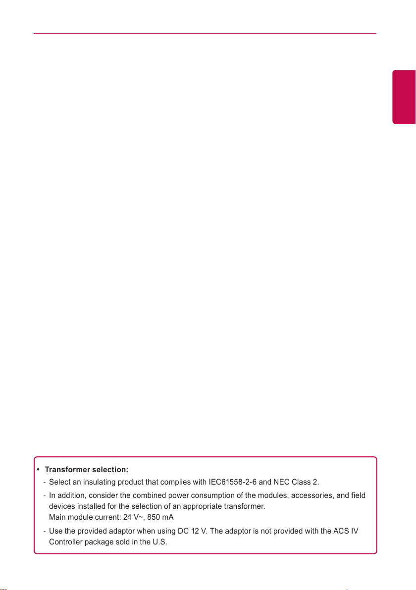
y Transformer selection:
- Select an insulating product that complies with IEC61558-2-6 and NEC Class 2.
- In addition, consider the combined power consumption of the modules, accessories, and field
devices installed for the selection of an appropriate transformer.
Main module current: 24 V~, 850 mA
- Use the provided adaptor when using DC 12 V. The adaptor is not provided with the ACS IV
Controller package sold in the U.S.
SAFETY PRECAUTIONS
6
Class A device
ENGLISH
NOTES
This equipment has been tested and found to comply with the limits for a Class A digital device,
pursuant to part 15 of the FCC Rules.
These limits are designed to provide reasonable protection against harmful interference when
the equipment is operated in a commercial environment.
This equipment generates, uses, and can radiate radio frequency energy and, if not installed
and used in accordance with the instruction manual, may cause harmful interference to radio
communications. Operation of this equipment in a residential area is likely to cause harmful
interference in which case the user will be required to correct the interference at his own
expense.
Caution
Changes or modifications not expressly approved by the manufacturer responsible for
compliance could void the user’s authority to operate the equipment.
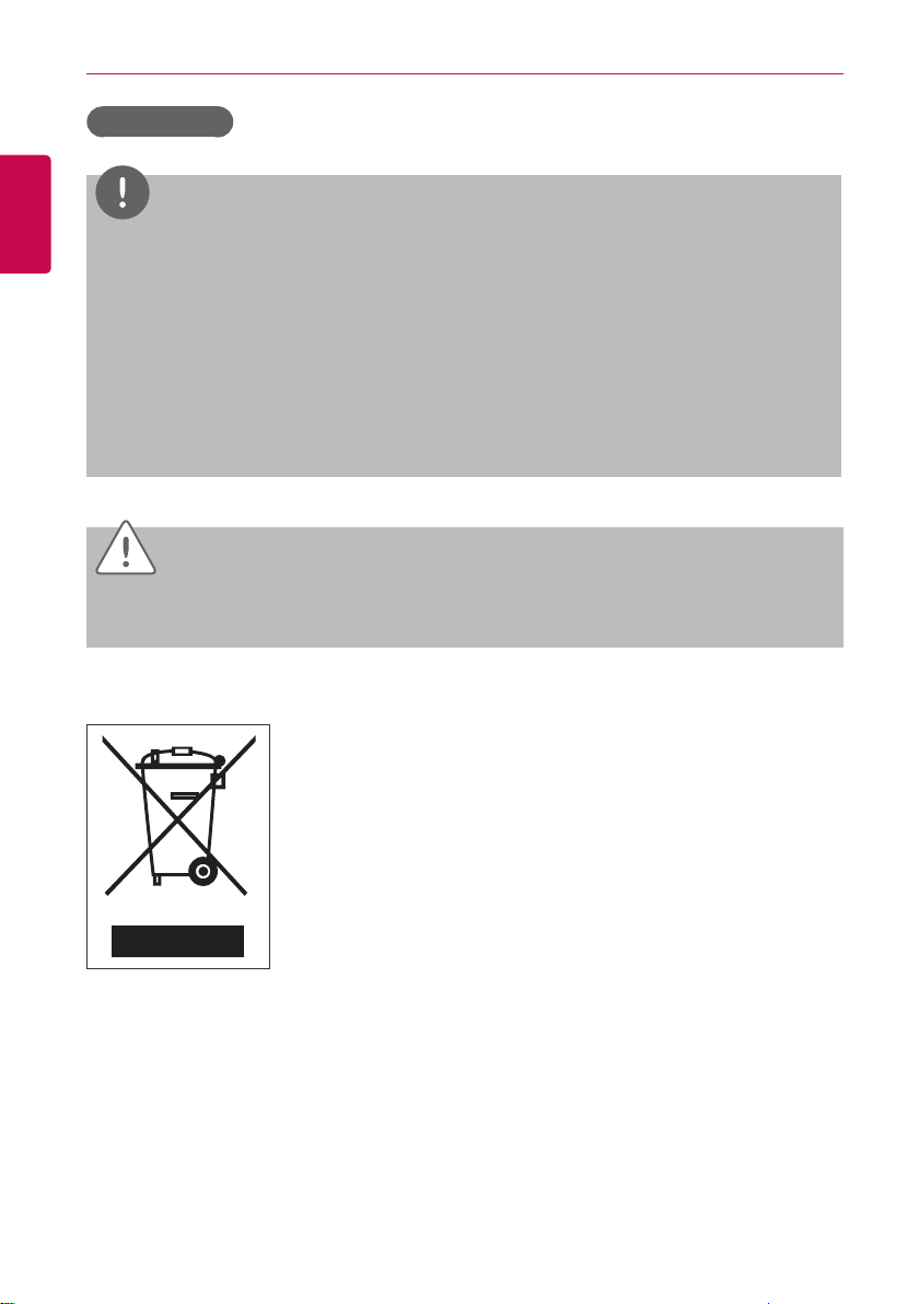
Disposal of your old appliance
1. When this crossed- out wheeled bin symbol is attached to a product it
means the product is covered by the European Directive 2002/96/EC.
2. All electrical and electronic products should be disposed of separately
from the municipal waste stream via designated collection facilities
appointed by the government or the local authorities.
3. The correct disposal of your old appliance will help prevent potential
negative consequences for the environment and human health.
4. For more detailed information about disposal of your old appliance,
please contact your city o!ce, waste disposal service or the shop
where you purchased the product.

STARTING
7
STARTING
This section explains how to connect to the system and register devices to setup the environment
(prior to using ACS IV Controller).
Login and logout
The following explains how to log in and out of ACS IV Controller.
ACS IV Controller can be controlled by entering the IP address of the ACS IV Controller in the
address bar of Internet Explorer without the installation of another program. The ACS IV Controller
Web server is executed automatically.
ENGLISH
STARTING
8
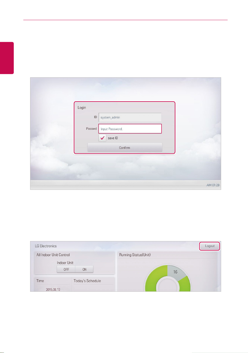
Login
You can login as follows:
ENGLISH
1. Run ACS IV Controller.
2. After entering your ID and password in the login window, click(touch) the [Confirm] button.
• You should be logged in now.
Logout
You can logout as follows:
1. On the top right of the ACS IV Controller home screen, click(touch) the [Logout] button.
• You should be logged out now.
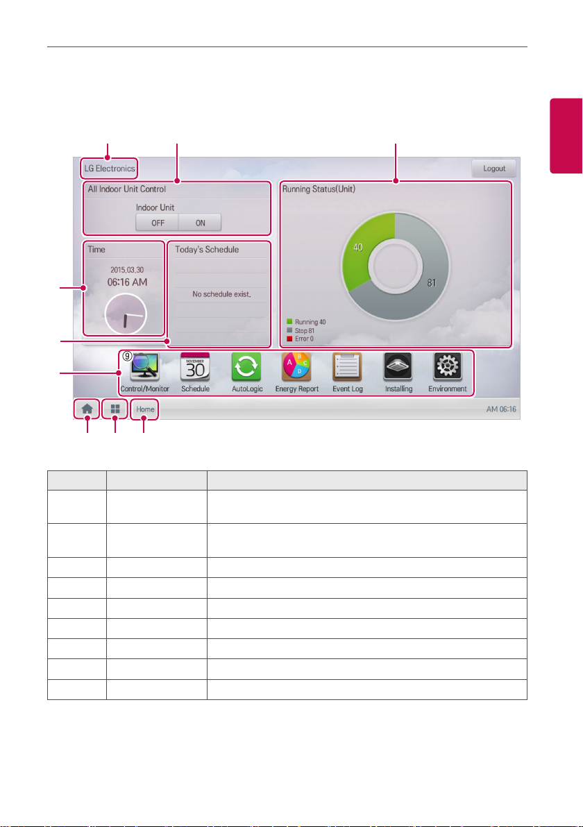
Home screen composition and features
The following explains the home screen composition and features.
STARTING
9
ENGLISH
⑨
① ②
③
④
⑨
⑤
⑥ ⑦ ⑧
Number Item Description
①
②
③
④
⑤
⑥
⑦
⑧
⑨
All Indoor Unit
Control
Running Status
(Unit)
Time Check the current date and time.
Today's Schedule Check the registered schedules in chronological order.
Main Menu Use ACS IV Controller main menu.
Home Return to the home screen.
View Menu Display the active menu.
Current Menu Display the name of the active menu.
Site name Display registered site name.
ON / OFF control of all indoor units.
Checks if the devices are operating, stopped, or in error.
STARTING
10
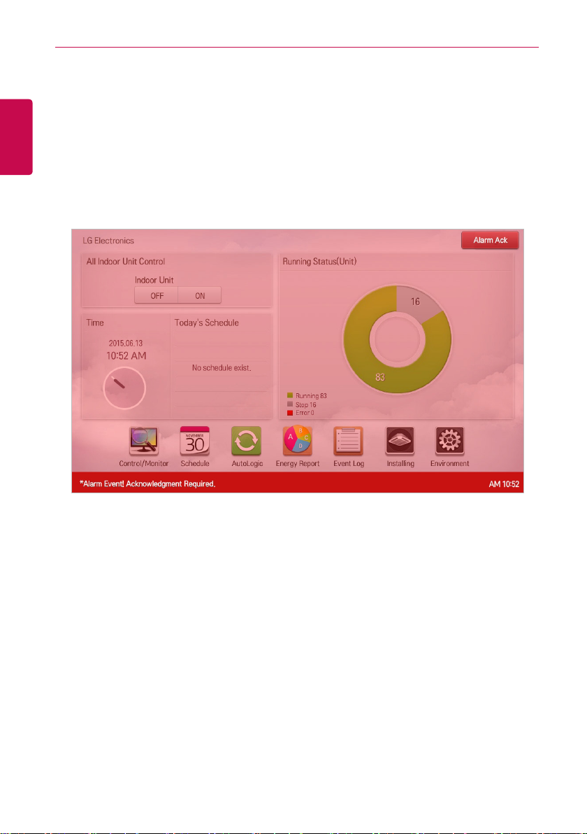
Emergency situation occurrence and reset
ENGLISH
When an Alarm ACK Required program occurs, the entire home screen turns red to indicate
Acknowledgement is required. The alarm condition must be cleared before any other control can be
performed. For details on how to set emergency program, refer to Managing Program.
Emergency situation occurrence
When an emergency situation occurs, the alert screen is displayed on home screen as follows.
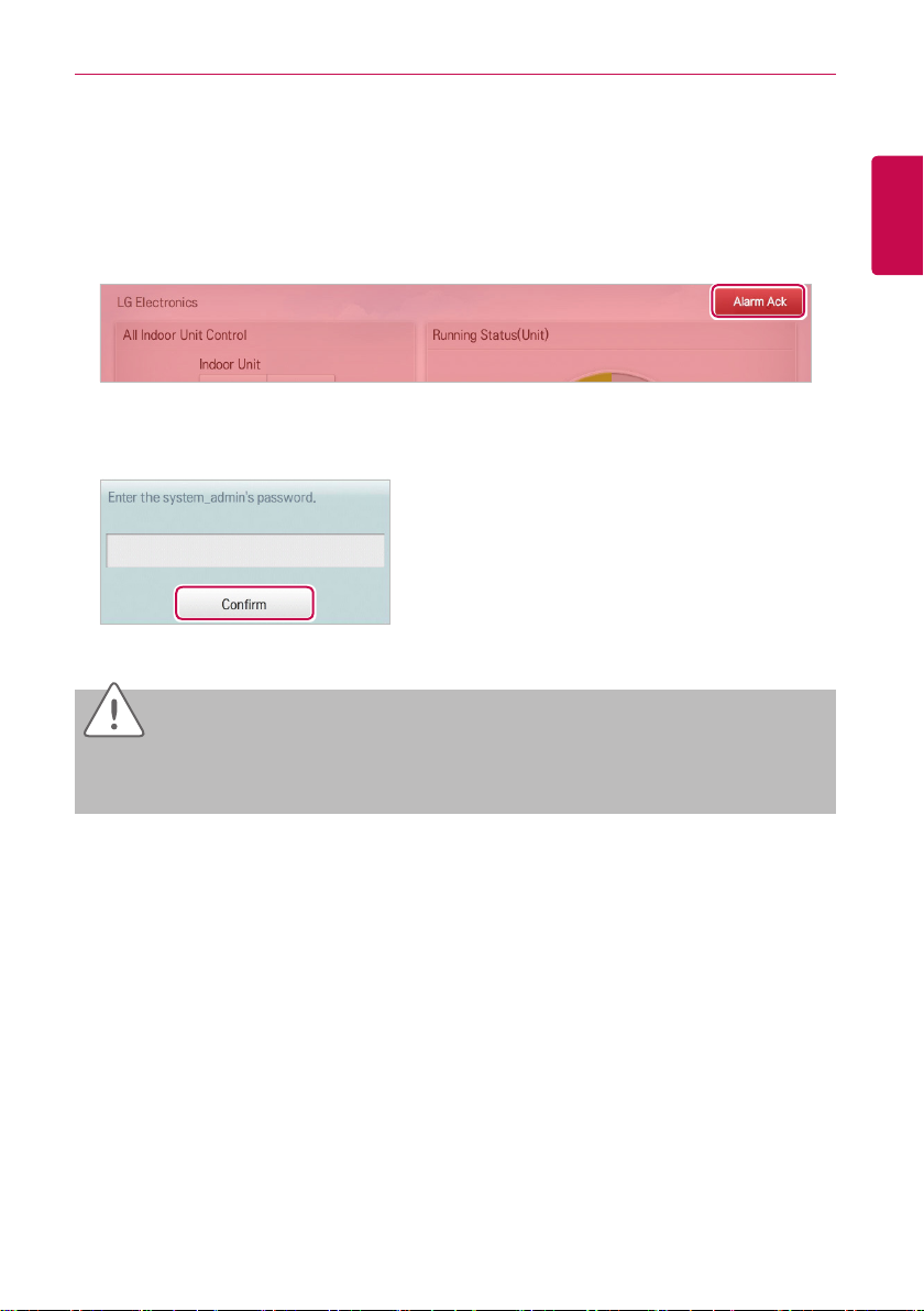
Emergency situation reset
Emergency alert screen is maintained until the emergency situation is reset. You can reset
emergency situation as follows.
1. Tou ch [Alarm Ack] button at the top right side of the emergency situation screen.
• Manager password input screen is displayed.
2. Input manager password and touch [Confirm] button.
• If the password is correct, the emergency situation is reset.
STARTING
11
ENGLISH
Caution
Emergency situation notice will be generated again until the cause of emergency situation is
removed. You may have to check Interlocking to determine what the alarm cause is.

12
ENGLISH
MEMO
USING THE PROGRAM
13
USING THE PROGRAM
The following explains how to use the ACS IV Controller functions.
Control/Monitor
Control/Monitoring is the menu to combine several devices that can be commonly monitored into one
unit for easy management. The following explains the Control/Monitor menu options.
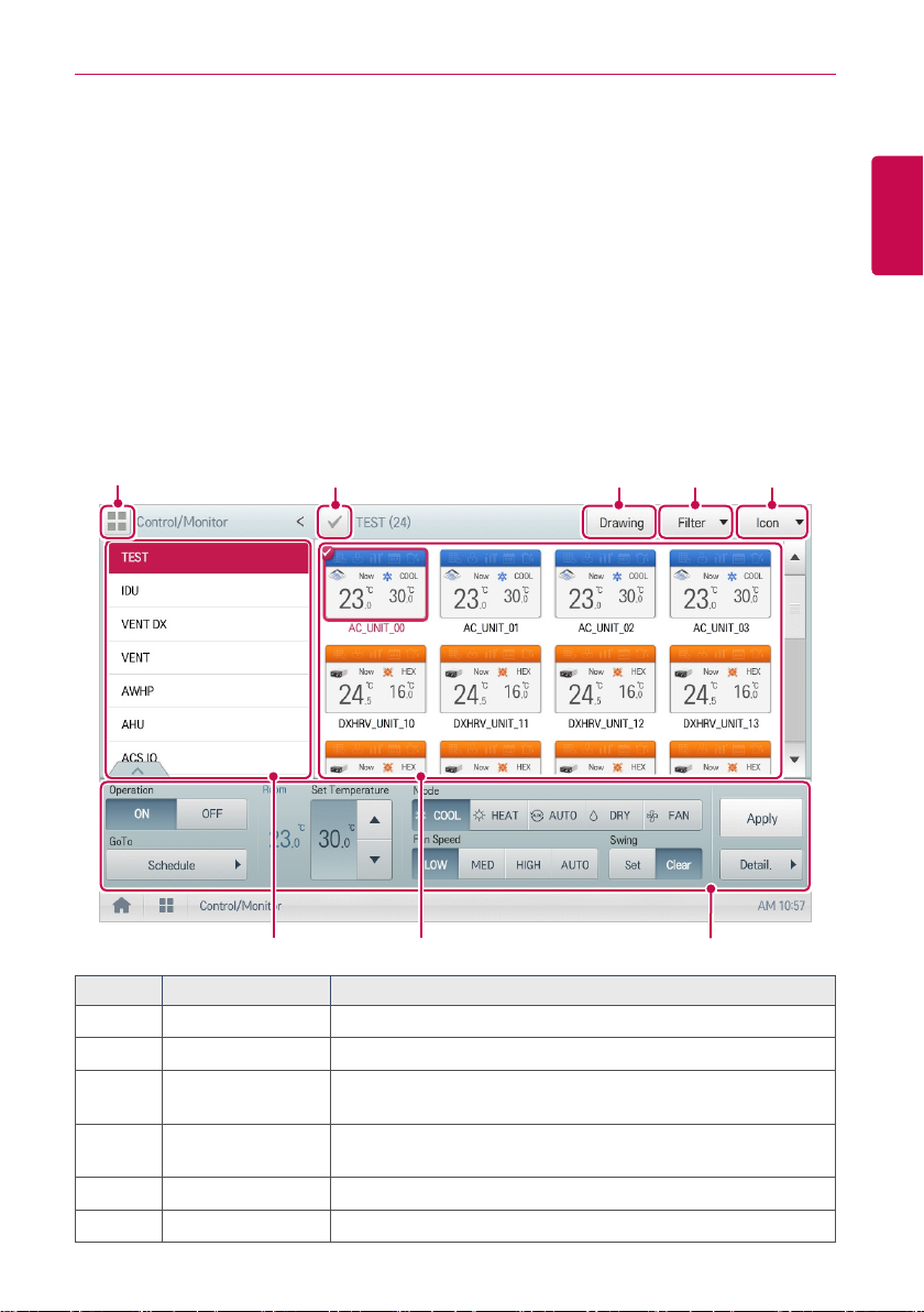
Control/Monitoring screen composition and features
The following explains Control/Monitoring screen composition and features.
⑧
① ② ③ ④
ENGLISH
⑤ ⑥ ⑦
Number Item Description
Select/Deselect All Select/deselect all devices in a group (select = red check).
①
②
③
④
⑤
⑥
[Drawing] Button View floor plans of a group.
[Filter] Button
View Type Select
Group List Check device group listings.
Monitoring Screen Check the control status of a device.
Select which device types are displayed for monitoring and
control.
Select a view type(Icon/Simple) for the monitoring screen.
(Refer following View Type)
USING THE PROGRAM
14
Number Item Description
ENGLISH
Device Control Box
⑦
⑧
[Multiple Group
Selection] Button
y Display the device control menu.
y The device control box shows different menus depending on
the device. (For more on Control Menu per Device)
y Control the device by selecting multiple groups.
View Type
Control/Monitor menu has two different types of view(Icon, Simple). The following shows the screen
composition and features per view type.
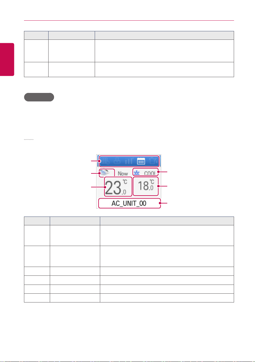
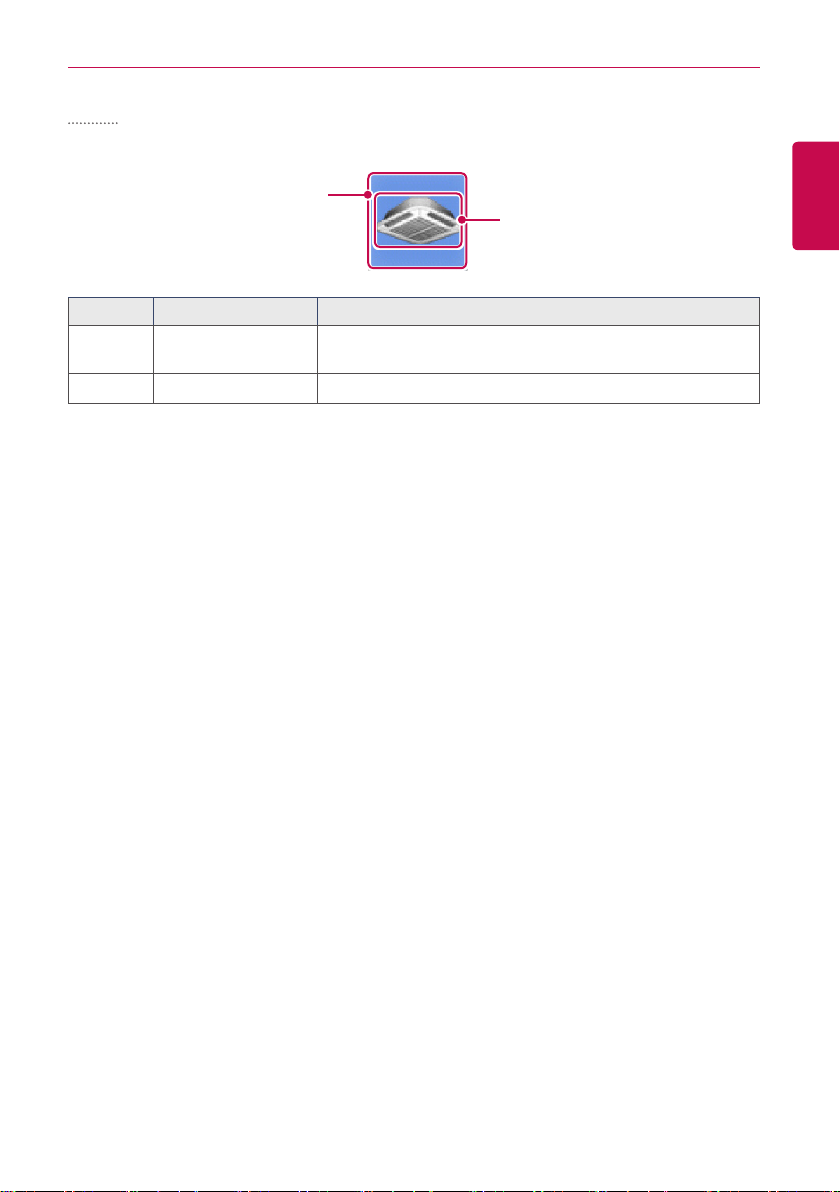
Icon
The control status is shown in icons. The device icon has a composition and feature as follows.
①
②
③
④
⑤
⑥
Number Item Description
①
②
③
④
⑤
⑥
Operation Mode and
Device Status Icon
Device Icon
Current Temperature Display the current temperature.
Operation Mode Display the operation mode of the device.
Desired Temperature Display the desired temperature.
Device Name Display the name of the device.
The color at the top of the icon box shows the current
operation mode, and the status of the device is indicated as
an icon.
The device to be controlled is indicated as an icon.
(The device shown may not represent the appearance of the
actual unit.)
Simple
USING THE PROGRAM
15
The control device and operation mode are displayed only.
①
②
Number Item Description
①
②
Operation Mode
Device Icon The device to be controlled is indicated as an icon.
The color of the box indicates the current operation mode.
Refer to following section.
ENGLISH
USING THE PROGRAM
16
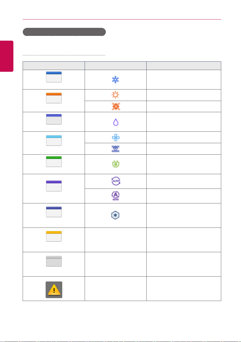
Monitoring screen colors and icons
ENGLISH
Box colors and operation mode per icon
Color Icon Operation Mode
(Blue)
Cooling
Heating
(Orang e)
(Navy)
(Sky Bl ue)
(Green)
(Pur ple)
(Sapphire Blue)
(Yell o w)
(Gray)
Ventilation, Electric Heat
Dehumidification
Fan
Ventilation, General
Power Saving
Auto
Ventilation, Auto
Chiller, Ice
- ON or Short
- OFF or Open
- Error
Device status icon
USING THE PROGRAM
17
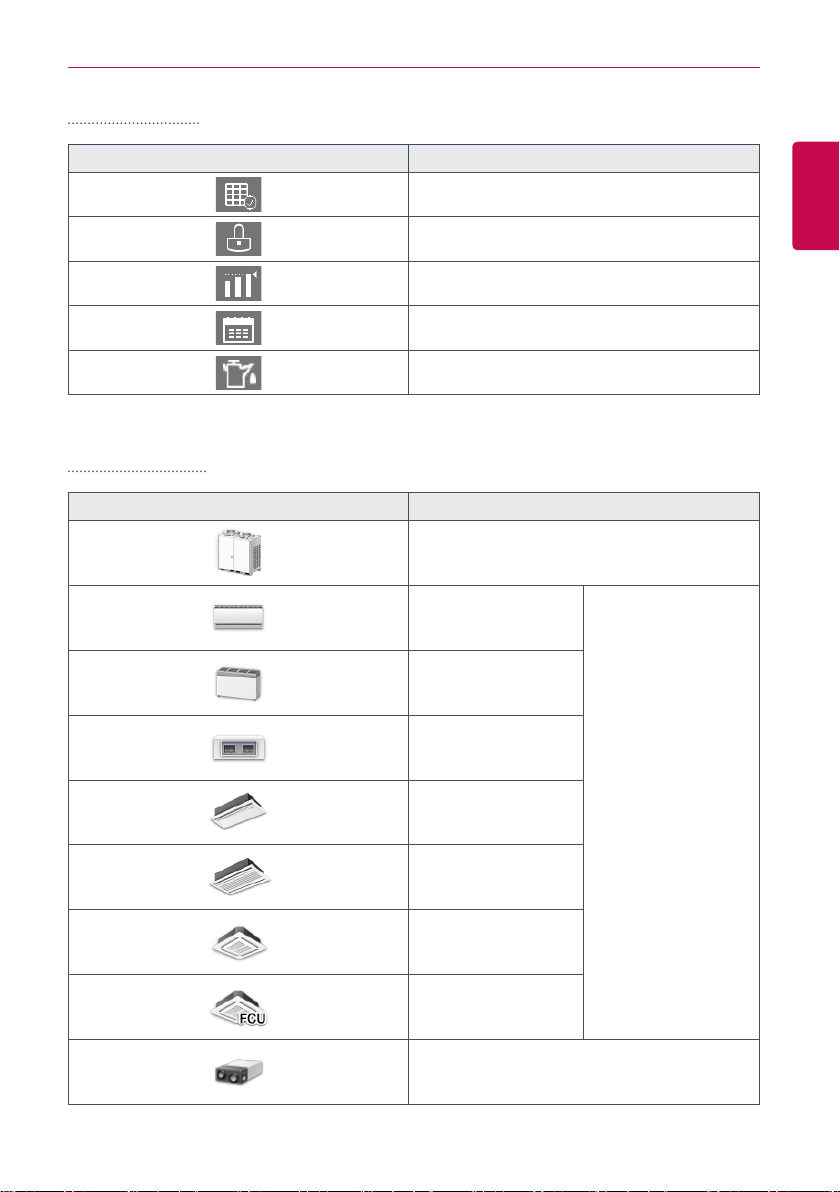
Control device icon
Icon Device Status
Filter Exchange
Full Lock On
Peak/Demand Control
Schedule
GHP Oil Alarm
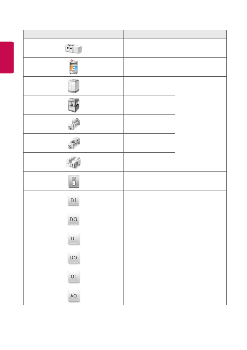
Icon De vice Type
Outdoor Device
Wall Mounted
Floor Mounted
ENGLISH
Duct
Cassette(1Way)
Cassette(2Way)
Cassette(4Way)
FCU
ERV, ERV DX
Indoor Device
USING THE PROGRAM
18
ENGLISH
Icon De vice Type
AHU
AWHP or Hydrokit
Water-cooled scroll
chiller
Air-cooled scroll chiller
Turbo chiller
Screw chiller
ABS chiller
DI
DO
UI
Chiller
DOKIT
DI
DO
Exp. I/O
AO

USING THE PROGRAM
Device Control
You can control the devices as follows.
1. From the main menu, click(touch) the [Control/Monitor] menu icon.
2. Click(Touch) the device group you want to control from the group list.
• The monitoring screen for the device is displayed.
3. Click(Touch) the device you want to control.
• To select all devices, click(touch) the button at the top.
• The device control area appears at the bottom of the screen.
4. In the device control box, set the control status of the device.
• The device control box shows a different menu depending on the device. For information
about the control area for each device, refer to Control Menu per Device.
5. Once you have finalized the settings, click(touch) the [Apply] button.
19
ENGLISH
USING THE PROGRAM
20
Control Menu per Device
ENGLISH
The control box menu dif fers depending on the device. The following shows the control box menu
per device.
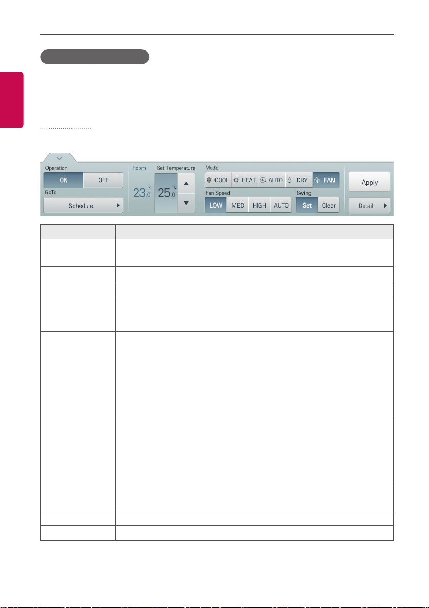
Indoor Device
The following is the indoor unit control menu and features.
Item Description
Operation
GoTo
Room Display the current temperature at configured sensor(s).
Set Temperature
Mode
Fan Speed
Swing
[Apply] Button Apply control menu setting to the device
[Detail. ▶] Button
y [ON] Button: Starts the operation of the device similar to occupied.
y [OFF] Button: Stops the operation of the device similar to unoccupied.
[Schedule▶] Button: Move to Schedule menu.
Click(Touch) [▲]/[▼] to set the temperature.
(The maximum/minimum temperatures that can be set may differ depending
on the model of unit controlled.)
y [COOL] Button: Cooling Mode Request.
y [H E AT ] Button: Heating Mode Request.
y [AUTO] Button: Evaluates the operating environment conditions and
automatically sets the mode of operation.
y [DRY] Button: You cannot set the temperature in this mode.
y [FAN] Button: Fan runs without temperature control to clean the air. You
cannot set the temperature in this mode.
y [LOW] Button: Slow fan speed.
y [MED] Button: Medium fan speed.
y [HIGH] Button: Fast fan speed.
y [AUTO] Button: Fan speed automatically adjusts between low, medium
and high fan speeds.
y [Set] Button: Turns on automatic oscillation of the louvers if present.
y [Clear] Button: Turns off automatic oscillation of the louvers if present.
Controls details.
USING THE PROGRAM
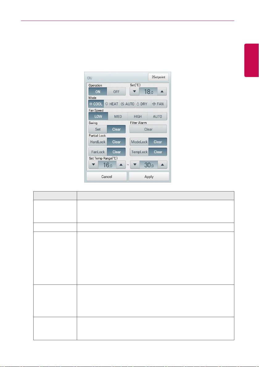
• Indoor unit fine control
In the control menu of the indoor unit, touch [Detail. ▶] button, and in the displayed detail
control window, you can control detail items. The composition and functions of the detail menu
are as follows.
21
ENGLISH
Item Description
y [ON] Button: Starts the operation of the device similar to occupied.
Operation
Set Click(Touch) [▲]/[▼] to set the temperature.
Mode
Fan Speed
Swing
y [OFF] Button: Stops the operation of the device similar to
unoccupied.
y [COOL] Button: Cooling Mode Request.
y [H E AT ] Button: Heating Mode Request.
y [AUTO] Button: Evaluates the operating environment conditions and
automatically sets the mode of operation.
y [DRY] Button: You cannot set the temperature in this mode.
y [FAN] Button: Fan runs without temperature control to clean the air.
You cannot set the temperature in this mode.
y [LOW] Button: Slow fan speed.
y [MED] Button: Medium fan speed.
y [HIGH] Button: Fast fan speed.
y [AUTO] Button: Loops from low to medium to high fan speeds.
y [Set] Button: Turns on automatic oscillation of the louvers if present.
y [Clear] Button: Turns off automatic oscillation of the louvers if
present.
USING THE PROGRAM
22
ENGLISH
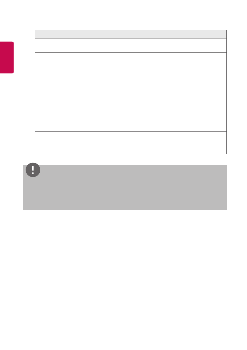
Item Description
Filter Alarm
Partial Lock
Set Temp Range Click(Touch) [▲]/[▼] to set the temperature limit.
[2Setpoint] or
[IDU 2Set] Button
Click(Touch) the Disable button to deactivate the filter exchange alarm.
(Model dependant.)
y [HardLock] Button: Disables thermostat control for all features.
y [Clear] Button: All functions are unlocked.
y [ModeLock] Button: Disables thermostat control for local mode
setting.
y [Clear] Button: Mode is unlocked.
y [FanLock] Button: Disables thermostat control for local fan speed
setting.
y [Clear] Button: Fan speed is unlocked.
y [TempLock] Button: Disables thermostat control for local
temperature setting.
y [Clear] Button: Temperature setting is unlocked.
Set functions in 2Setpoint or IDU 2set(US only Option)
NOTES
Depending on the installation site specifications, either the Auto Mode or 2Set Auto Mode
y
can be selected. Go to
desired auto mode type.
2Set Auto Mode option is only available in the U.S.
y
Environment > Advance Setting > Auto Mode Option
and select a
 Loading...