

Page 1

LG
PI485 GATEWAY
INSTALLATION MANUAL
LG
Models: PHNFP14A0
PSNFP14A0
IMPORTANT
• Please read this installation manual completely
before installing the product.
• Installation work must be performed in
accordance with the national wiring standards
by authorized personnel only.
• Please retain this installation manual for future
reference after reading it thoroughly.
Page 2

2 485 Gateway(M)
Central Control Unit Use & Care Manual
TABLE OF CONTENTS
■ Part Installation & Operation precution .....................3~4
■ Part Description ...........................................................5
■ Installation Guide ..........................................................7
■ Installation Steps .................................................................................7
■ DIP Switch Configuration.....................................................................8
■ Simple Central Controller - Connection Diagram ..............................10
■ Deluxe Central Controller - Connection Diagram ..............................12
■ Examples For Product Installation .....................................................13
■ Accessory Parts .........................................................14
Page 3
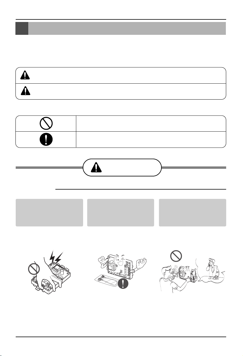
Safety Precautions
Installation Manual 3
Don't touch with the
hands while the power is
on
•
There is risk of fire or electric
shock.
Use standard
parts(connector).
•
Do not disassemble or repair
the product. There is risk of fire
or electric shock.
For electrical work, contact
the dealer, seller, a qualified
electrician, or an Authorized
Service Center.
•
Do not disassemble or repair
the product. There is risk of fire
or electric shock.
■ Installation
O
N
L
1 2 3
4
K
S
D
O4H
Safety Precautions
To prevent injury to the user or other people and property damage, the following instructions
must be followed.
■ Incorrect operation due to ignoring instruction will cause harm or damage. The seriousness is
classified by the following indications.
■ Meanings of symbols used in this manual are as shown below.
This symbol indicates the possibility of death or serious injury.
This symbol indicates the possibility of injury or damage.
Be sure not to do.
Be sure to follow the instruction.
WARNING
WARNING
CAUTION
4
O4H
D
S
3
K
2
N
O
1
L
KSDO4H
ON
L1 2 3 4
Page 4
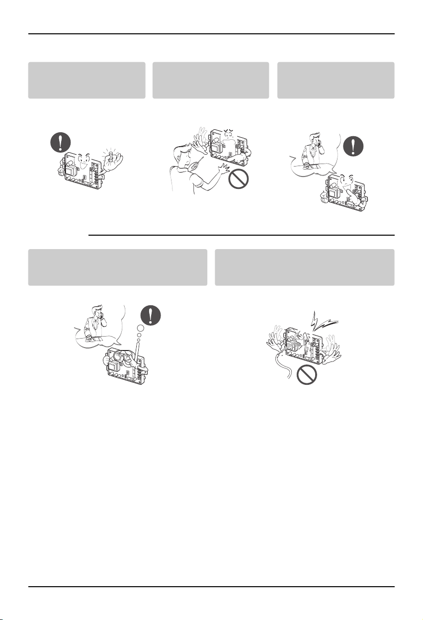
Safety Precautions
4 485 Gateway(M)
When the product is soaked (flooded or
submerged), contact an Authorized Service
Center.
• There is risk of fire or electric shock.
Be cautious that water could not enter the
product.
• There is risk of fire, electric shock, or product
damage.
■ Operation
Use the correctly rated
breaker or fuse.
• There is risk of fire or electric
shock.
Do not install, remove, or reinstall the unit by yourself
(customer).
• There is risk of fire, electric
shock, explosion, or injury.
For installation, always
contact the dealer or an
Authorized Service Center.
• There is risk of fire, electric
shock, explosion, or injury.
O4H
D
4
S
K
N
O
1 2 3
L
O4H
D
4
KS
3
N
2
O
L1
O4H
D
4
S
K
3
2
N
O
1
L
O4H
4
SD
K
3
N
2
O
1
L
O4H
D
4
S
K
3
N
O
1 2
L
Page 5
Part Description
Installation Manual 5
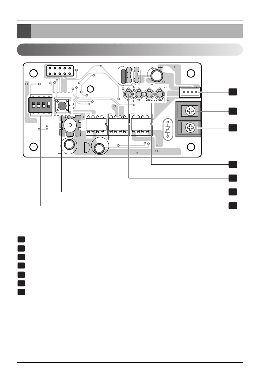
Part Description
PHNFP14A0
PI485 GATEWAY(C)
CN_OUT: Indoor Unit Connector
BUS_B: RS-485 (-) Terminal
BUS_A: RS-485 (+) Terminal
LED01G,02G,03G: Communication Status LED
LED1: RS-485 Communication Status LED
Reset Switch: PI485(C) Reset
DIP Switch: Product Select (Refer Page 8)
S1
BR1
TANS01Y
ZNR01Y
U02YU04YU03Y
SWITCH
LED1
LED01G
LED02G
LED03G
OSC01B
L02D
L01D
C01A
IC01A
CN_COMM
C03Y
C04Y
ON
L1 2 3 4
1
2
3
4
5
6
7
1
2
3
4
5
6
7
Page 6

6 485 Gateway(M)
Part Description
PSNFP14A0
PI485 GATEWAY(R)
CN_OUT: Indoor Unit Connector
BUS_A: RS-485 (+) Terminal
BUS_B: RS-485 (-) Terminal
LED01G,02G,03G: Communication Status LED
LED1: RS-485 Communication Status LED
Reset Switch: PI485(C) Reset
DIP Switch: Product Select (Refer Page 9)
1
2
3
4
5
6
7
ON
L1 2 3 4
2
3
1
5
7
6
4
Page 7

Installation Manual 7
Installation Guide
Installation Steps (PHNFP14A0/PSNFP14A0)
1. Select DIP Switch Configuration(Refer page 8 or 9)
2. Connect The RS-485 BUS_A(+), BUS_B(-) with Other Network Products (ex,
Simple Central Controller , CNU.....)
3. Connect CN_OUT with Outdoor Unit by the cable (provided)
4. Check the Communication Status LED
- LED01G(Red): Ok operation-LED blinks for 5times and is OFF.
This process is repeated after every 3 minutes
• NG operation : Check The Indoor unit address & Wiring Connections
- LED02G(Yellow) ,LED03G(Orange): Ok operation-LED's blinks continuously
• NG operation : Check The DIP Switch setting & Wiring Connections
5. Check the RS-485 Communication Status LED:
■ Ok operation
(1) LED's blinks 2 Times in every 10~30 seconds (In case Connected CNU)
(2) LED's blinks continuously (In case Connected Simple Central Controller)
■ NG operation : Check The Wiring Connections
6. Finally if all the above steps are OK then , Tie the cables by Tie Wraps & Clamp
Installation Guide
1
7
4
5
2
3
Page 8

8 485 Gateway(M)
Installation Guide
ON KSDO 4H
S1
BR1
TANS01Y
ZNR01Y
U02YU04YU03Y
SWITCH
LED1
LED01G
LED02G
LED03G
OSC01B
L02D
L01D
C01A
IC01A
CN_COMM
C03Y
C04Y
ON
L1 2 3 4
L1 2 3 4
Select Air
Conditioner Type
Select Network
Type
ON KSDO4H
ON KSDO4H
L1 2 3 4
L1 2 3 4
DIP Switch Configuration
3 ON+ALL OFF: Using LGAP CAC/RAC/SRAC/PAC Products
Configuration Methods
3, 4 ON+ALL OFF: LGAP CAC/RAC/SRAC/PAC Products + Central
Controller (ALL type)-Using LGAP
Using LGAP CAC/RAC/SRAC/PAC Products Configuration Methods
• PHNFP14A0
CAUTION:
Wrong Products Configuration can lead to malfunctioning
Page 9

Installation Guide
Installation Manual 9
k
ON KSDO4H
ON KSDO4H
L1 2 3 4
L1 2 3 4
3 ON+ALL OFF: LGAP CAC/RAC/SRAC/PAC Products + Central
Controller (ALL type)-Without LGAP
3, 4 ON+ALL OFF: LGAP CAC/RAC/SRAC/PAC Products + Central
Controller (ALL type)-Using LGAP
Using LGAP CAC/RAC/SRAC/PAC Products Configuration Methods
• PSNFP14A0
CAUTION:
Wrong Products Configuration can lead to malfunctioning
ON
L1 2 3 4
Select Air
Conditioner Type
ON KSDO 4H
L1 2 3 4
Select Networ
Type
Page 10

10 485 Gateway(M)
Installation Guide
S1
BR1
TANS01Y
ZNR01Y
U02YU04YU03Y
SWITCH
LED1
LED01G
LED02G
LED03G
OSC01B
L02D
L01D
C01A
IC01A
CN_COMM
C03Y
C04Y
ON
L1 2 3 4
Indoor Main PCB
Simple Central
Controller
DC 10V
VCC
Bus B
CN_OUT
CN_COMM
Bus A
GND
D
C
Indoor Main PCB
CN_CC
CN_CC
PI485 GATEWAY
Simple Central Controller
CENTRAL
CONTROL
UNIT
Simple Central Controller - Connection Diagram
CAUTION:
After Product Installation Tie the cables with the clamps & Tie-Wraps provided.
• PHNFP14A0
Page 11

Installation Guide
Installation Manual 11
Indoor Main PCB
Simple Central
Controller
DC 10V
VCC
Bus B
Bus A
GND
D
C
Indoor Main PCB
CN_CC
CN_CC
PI485 GATEWAY
Simple Central Controller
CENTRAL
CONTROL
UNIT
ON
L1 2 3 4
ON
L1 2 3 4
CAUTION:
After Product Installation Tie the cables with the clamps & Tie-Wraps provided.
• PSNFP14A0
Page 12

12 485 Gateway(M)
Installation Guide
S1
BR1
TANS01Y
ZNR01Y
U02YU04YU03Y
SWITCH
LED1
LED01G
LED02G
LED03G
OSC01B
L02D
L01D
C01A
IC01A
CN_COMM
C03Y
C04Y
ON
L1 2 3 4
Indoor Main PCB
Bus B
Bus A
Bus B
Bus A
Bus B
Bus A
PI485 GATEWAY
PCB
PI485 GATEWAY
PCB
CN_CC
Indoor Main PCB
CN_CC
CNUPCB
Bus B
Bus A
CNUPCB
O
N
L1
2 3 4
Deluxe Central Controller - Connection Diagram
CAUTION:
After Product Installation Tie the cables with the clamps & Tie-Wraps provided.
• PHNFP14A0
• PSNFP14A0
Page 13

Installation Guide
Installation Manual 13
Examples For Product Installation
CAUTION:
It can be Different location of installation in order to Each Product structure
(1) The Installation for 4Way Cassette
Product
→ Check Screw boss for PCB in 4way
Cassette Product Then fix It
(2) The Installation for DUCT Product
→ Using PCB Holder provided
(3) The Installation for Cassette Product
Cover
→ Check Screw boss for PCB in 4way
Cassette Product Then fix It
Page 14

14 485 Gateway(M)
Acceassory Parts
Acceassory Parts
S1
BR1
TANS01Y
ZNR01Y
U02YU04YU03Y
SWITCH
LED1
LED01G
LED02G
LED03G
OSC01B
L02D
L01D
C01A
IC01A
CN_COMM
C03Y
C04Y
ON
L1 2 3 4
PCB :6871A20484B Holder for DUCT :3110A 20056A WIRE ASSY 1(for RAC/SRAC/CAC)
Screw 4 EA Installation Manual WIRE ASSY(for Others)
ON
L1 2 3 4
PCB :6871A20484C
WIRE ASSY 1(for RAC/SRAC/CAC)
WIRE ASSY(for Others)
Screw 4 EA Installation Manual
* Others : Tie Wrap (3 EA) - Cable Tie
Clamp (1 EA)
• PSNFP14A0
• PHNFP14A0
Page 15

P/No.: 3828A20365Q
After reading this manual, keep it in a place easily accessible to the user for future reference.
Printed in Korea
 Loading...