

Page 1
www.lg.com
Solar Accessories kit
PHLLA
Please read this installation manual completely before installing the product.
Installation work must be performed in accordance with the national wiring
standards by authorized personnel only.
Please retain this installation manual for future reference after reading it
thoroughly.
INSTALLATION MANUAL
AIR
CONDITIONER
P/NO : MFL62047302
Safety Precautions
Be sure to request to the service
center or installation specialty store
when installing products.
Request to the service center or
installation specialty store when
reinstalling the installed product.
Do not disassemble, fix, and modify
products randomly.
Welding operations need attention
in the fire.
■ Installation
WARNING
Safety Precautions
To prevent injury to the user or other people and property damage, the following instructions must be followed.
■ Incorrect operation due to ignoring instruction will cause harm or damage. The seriousness is classified by
the following indications.
WARNING
CAUTION
This symbol indicates the possibility of death or serious injury.
This symbol indicates the possibility of injury or damage.
Installation Procedure
Step 5 : Connecting sensor
s and PCB setting
Open control box of the indoor unit and find connector ‘CN_TH4’ on the PCB. Connect
sensor into ‘CN_TH4’.
Insert sensor with RED wire into Tee pipe. Also, insert sensor with BLACK wire into
sanitary tank.
Find DIP switch on the PCB. Change DIP switch setting as following :
• DIP switch No. 2 : ON (white bar should be located on the right side)
• DIP switch No. 3 : OFF (white bar should be located on the left side)
Sensor mounting
Installation Procedure
Installation Procedure
Check following conditions before installation.
• Pipe diameter of solar thermal system : Tee pipe of solar kit is 22mm diameter. If diameters
between pipe of solar thermal system and tee pipe of solar kit are different, pipe diamter reducer
or expander, which is field supplying, will be required.
• Working space for pipe welding or pipe cutting : Tee pipe of solar kit should be inserted into
existing pipe of solar thermal system. To do insert job, cutting of existing solar thermal system
pipe and welding of existing solar thermal system pipe and tee pipe of solar kit is required after
securing enough working space.
• Preparation for working fluid drainage and refilling : While installing solar kit, drainage of working
fluid and refilling is required. Be ready to do these jobs.
Step 1 : Check what will be installed
• If sanitary tank and solar kit are installed while installation, please read
Step 2-1.
• If sanitary tank is already installed and only solar kit is installed while
installation, please read Step 2-2.
Step 2-1 : If Sanitary tank and Solar kit are installed
• Check if sanitary tank model name is LGRTV200VE / LGRTV300VE.
If not, solar kit can not be installed.
• Turn off main power to avoid accident such as electric shock.
• Install sanitary tank and sanitary tank kit according to related installation manuals.
These manuals can be found sanitary tank packaging box and sanitary tank kit packaging box.
Sensor inside sanitary tank kit will not be used while installation.
Instead,sensor inside solar kit will be used while installtion.
Step 2-2 : If Solar kit is installed (Sanitary tank is already installed)
• Check if sanitary tank model name is LGRTV200VE /
LGRTV300VE.
If not, solar kit can not be installed.
• Turn off main power to avoid accident such as electric
shock.
Remove sanitary tank sensor. It will be replaced with
different sensor which is a part of solar kit.
Sanitary tank sensor is located at the surface of the
sanitary tank at midddle height of tank.
• Open control box of the indoor unit and disconnect
sensor which is connceted at ‘CN_TH4’.
CAUTION
Installation Procedure
Step 3 : Pipeworking - Sanitary tank and Solar thermal system
Proceed water pipeworking according to following directions :
1. Connect Tee pipe and sensor plug.
2. Inside Tee pipe, metalic particles can be made after connecting Tee plug and sensor plug.
Cleaning inside of Tee pipe by flushing clean water. As metalic particles can be also made after
disconnecting Tee plug and sensor plug, do cleaning Tee pipe again.
3. While welding Tee pipe, sensor plug can be damaged due to welding heat.
To avoid thermal defect on sensor plug while welding, cover sensor plug with wet clothes.
4. Hot water from solar thermal system should be transferred to the upper inlet port of the heatin
coil of the sanitary tank.
5. Tee pipe should be located between sanitary tank and hot water pipe.
6. To fix Tee pipe, welding or other bonding method can be applied.
It can be determined by installer according to field installation condition.
Step 4 : Installing requried parts (field supply)
3way valve(field supply) is required. This 3way valve will be used to transfer or stop hot
water(generated by Solar thermal system) into heating coil of the sanitary tank.
It should be installed like below figure.
• Specification of 3way valve :
(1) : SPDT = Single Pole Double Throw. Three wires consist of Live1 (for selecting Flow A), Live 2
(for selecting Flow B), and Neutral (for common).
(2) : “Flow A” means ‘water flow from the indoor unit to under floor water circuit.’
(3) : “Flow B” means ‘water flow from the indoor unit to sanitary water tank.’
If necessary, additional water pump(field supply) can be installed to transfer hot water
when existing solar thermal system’s water pump capacity is not enough.
• Specification of the water pump is : 220V AC 50Hz
Part Description
Part Description
Double Thermistor sensor
12m(1EA)
Tube ConnectorHolder sensor
Installation Manual
Insert sensor into sensor socket and bolt it tightly.
A B
Installation Procedure
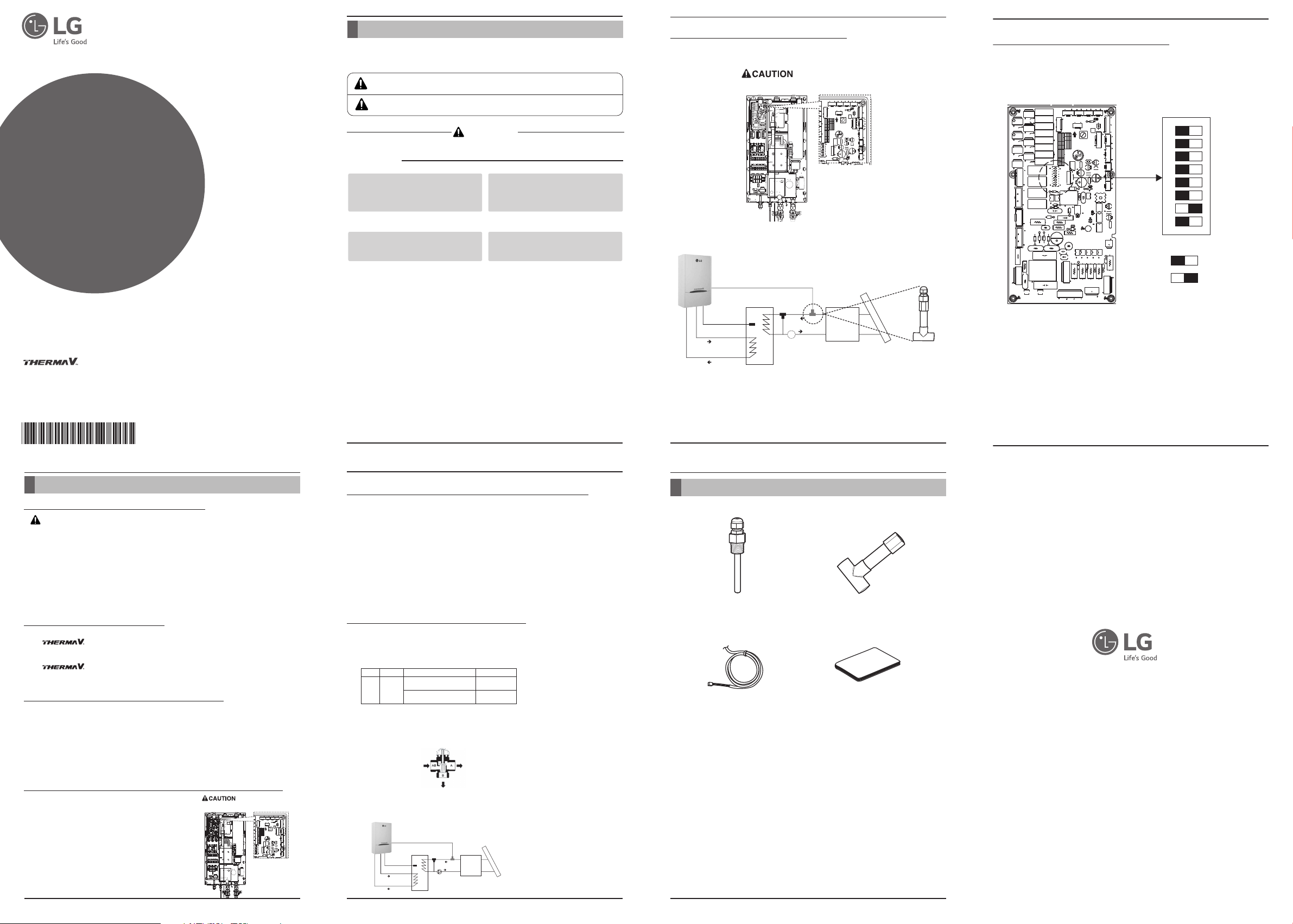
Step 5 : Connecting sensors and PCB setting
Find DIP switch on the PCB. Change DIP switch setting as following :
• DIP switch No. 2 : ON (white bar should be located on the right side)
• DIP switch No. 3 : OFF (white bar should be located on the left side)
- Close control box.
Water Tank Sensor
(less than 12 meter)
Water Out
Water In
C
Solar Thermal Sensor(RED)
(less than 12 meter)
Water Tank
3way valve
(Field Supply)
(Field Supply)
Pump
Water In
Water Out
Solar
Thermal
System
(Field Supply)
Solar
Collector
(Field Supply)
OFF
1
ON
2
3
4
5
6
7
8
OFF is selected
ON is selected
Sensor mounting
Insert sensor into sensor socket and bolt it tightly.
A B
C
3-wire
rType
Selecting “ Flow A” between
230V ACSPDT
Water Tank Sensor
(less than 12 meter)
Water Out
Water In
“ Flow A” and “ Flow B” (2)
Selecting “ Flow B” between
“ Flow A” and “ Flow B” (3)
Solar Thermal Sensor(RED)
(less than 12 meter)
3way valve
(Field Supply)
Pump
(Field Supply)
Water Tank
Water In
Water Out
(1)
Solar
Thermal
System
(Field Supply)
SupportedOperating ModePowe
Yes
Yes
Solar
Collector
(Field Supply)
 Loading...