

Page 1

Air Conditioning Technologies
CONTROLS &
ACCESSORIES
2017
1
Page 2
ABOUT LG
About LG Electronics USA, Inc.
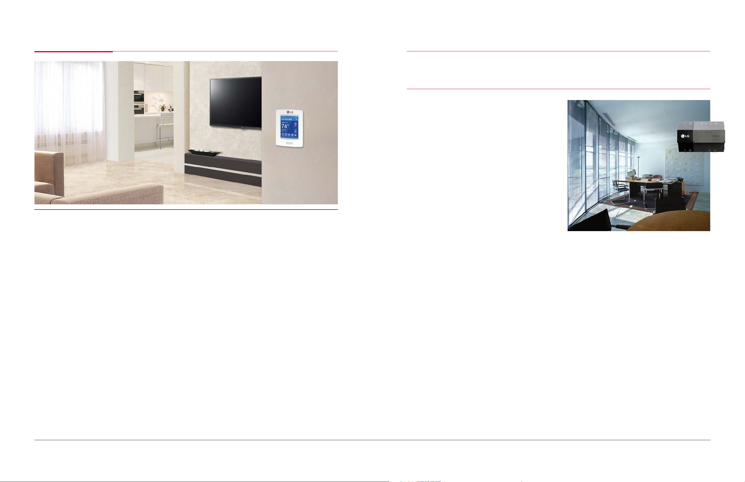
By utilizing advanced control strategies, LG Air Conditioning systems not only
save energy, they also increase operational convenience and living standards.
LG offers a variety of controls, including individual
zone control, central control, and building
management system integration control options
that scale easily to meet the requirements of jobs
small to large. User-friendly controllers from LG allow
users to control and monitor their entire system at
the touch of a button. Centralized controllers provide
building owners, facilities managers and maintenance
personnel with the ability to manage the entire LG
air conditioning system from a single location. This
allows convenient management of air conditioning
units and other facilities equipment—even in multiple
sites—which helps ensure the highest energy savings
are realized from the system.
LG Electronics USA, Inc., based in Englewood Cliffs, NJ, is the North American subsidiary of LG Electronics,
Inc., a $48 billion global force and technology leader in consumer electronics, home appliances and mobile
®
communications. LG Electronics, a proud ENERGY STAR
a range of stylish and innovative home entertainment products, mobile phones, home appliances, commercial
displays, air conditioning systems and solar energy solutions in the United States, all under LG’s “Life’s Good”
marketing theme. For more news and information on LG Electronics, please visit www.LG.com.
Partner of the Year for ve consecutive years, sells
LG Electronics USA Air Conditioning Technologies
The LG Electronics USA Commercial Air Conditioning business is based in Alpharetta, GA. LG is a leading
player in the global air conditioning market, manufacturing both commercial and residential air conditioners
and providing total sustainability and building management solutions. From consumer and individual units
to industrial and specialized air conditioning systems, LG provides a wide range of products for heating,
ventilating and air conditioning. For more information, please visit www.lghvac.com.
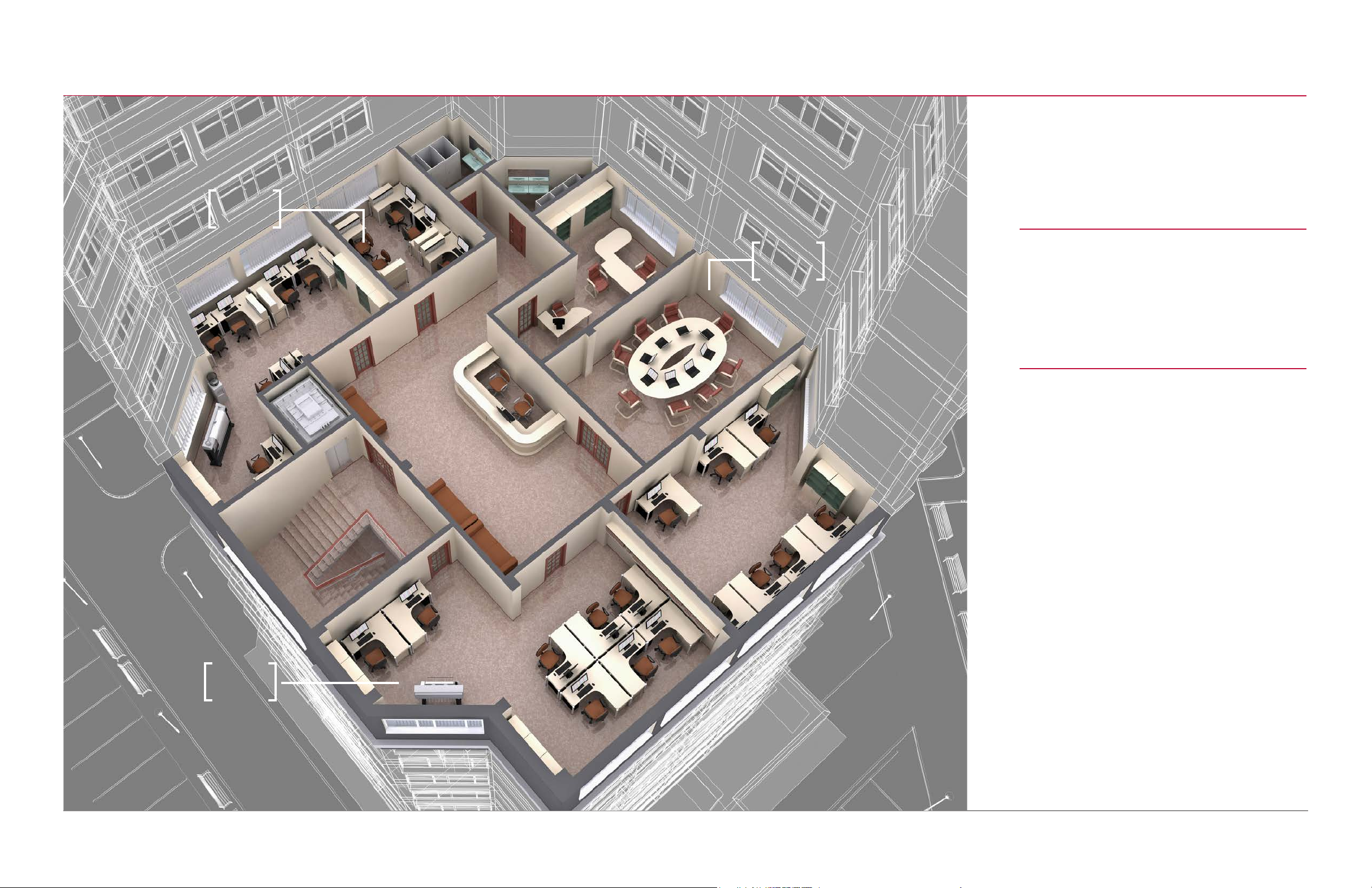
LG building controllers allow for interfacing with third-party building management systems and also
control sub-market segments such as lighting control, security control and access control. Built to be
compatible with the entire family of LG Air Conditioning Technologies products, LG controls are the best
way to achieve the highest performance from LG systems.
ENHANCED
ENERGY SAVINGS
CONVENIENCE
EASY TO INSTALL
While LG Air Conditioning systems are engineered for efficiency, there are many
ways that LG controls can help save even more energy with advanced features like
scheduling and setpoint range limiting.
LG controls come with features that make them easy to use and make LG systems
easy to control. From our touch screen interface on the AC Smart BACnet to modes
like auto-changeover, you are sure to be pleased with the aesthetic appeal of the
control as well as its ease of use.
The LG communications network is based on simple two-wire, daisy chain
architecture that reduces installation cost and complexity. This allows the system
to be installed by the mechanical contractor, eliminating the need for costly building
management system integration contractors and specialists.
LG Air Conditioning Technologies
1 2
Page 3
CONTENTS
72°
70°
CONTROLS
INDIVIDUAL CONTROLLERS
CENTRAL CONTROLLERS
SYSTEM INTEGRATION DEVICES
ACCESSORIES
MECHANICAL ACCESSORIES
HEAT RECOVERY UNIT
INDOOR ACCESSORIES
OUTDOOR ACCESSORIES
7
14
19
26
40
41
42
74°
LG Air Conditioning Technologies
3 4
Page 4
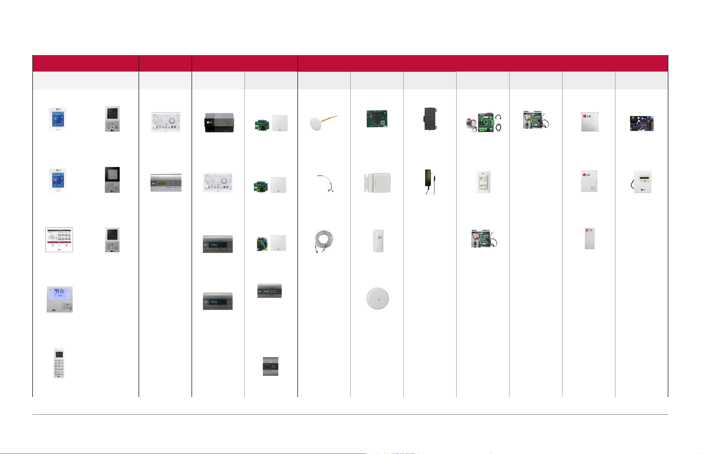
CONTROLS Lineup
INDIVIDUAL CONTROLLERS
Remote Controllers System Gateway Application Controllers
LG MultiSITE™ CRC1+
PREMTBVC1
LG MultiSITE™ CRC1
PREMTBVC0
Premium
Simple
PQRCVCL0QW
Simple
PQRCVCL0Q
Simple
CENTRAL
CONTROLLERS
AC Smart IV
PACS4B000 PBACNBTR0A
ACP IV
PACP4B001
SYSTEM INTEGRATION DEVICES
LG MultiSITE™
Communications
Manager
AC Smart IV BACnet
PBACNA000
ACP IV BACnet
Dry Contact for
Thermostat
PDRYCB300
Dry Contact for
Economizer
PQDSB1
Simple Dry Contact
Control Accessory
Remote Temperature
Button Sensor
ZRTBS01
Group Control Wire
PZCWRC1
Extension Cable
MultiSITE CRC1
Accessories
ZigBee Pro
Wireless Card
ZVRCZPWC1
Wireless Door/
Window Switch
ZVRCZDWS1
Wireless Wall
Occupancy Sensor
Wall Power Adapter
MultiSITE CM
Accessories
LON Module
ZHWLONWK0
ZHWPWADTR
Accessories
Outdoor Unit Water Source AHU Kit ERV
Low Ambient Kit
PRVC2
Cool / Heat Selector
PRDSBM
Variable Water Flow
Control Kit
Variable Water Flow
Control Kit
PWFCKN000
PRVC1
Communication Kit
PRCKAM
Communication Kit
PRDCAM
EEV Kit
PI-485 For ERV
PSNFP14A0
CO2 Sensor
PEXPMB000
PREMTA000
Standard
PREMTB10U
Wireless Remote
Controller
PQWRHQ0FDB
LG Air Conditioning Technologies
5 6
PQRCHCA0QW
PQNFB17C2
ACP LonWorks
PLNWKB100
PDRYCB100
PDI (Power
Distribution Indicator)
Premium (8 port)
PQNUD1S41
Standard (2 port)
PPWRDB000
IO Module
(Input / Output Module)
PEXPMB000
PZCWRC1
ZVRCZWOC1
Wireless Ceiling
Occupancy Sensor
ZVRCZCOC1
PWFCKN000
PRLK048A0 (8 Ton)
PRLK096A0 (16 Ton)
Page 5
AIR CONDITIONING
• INDIVIDUAL
CONTROL
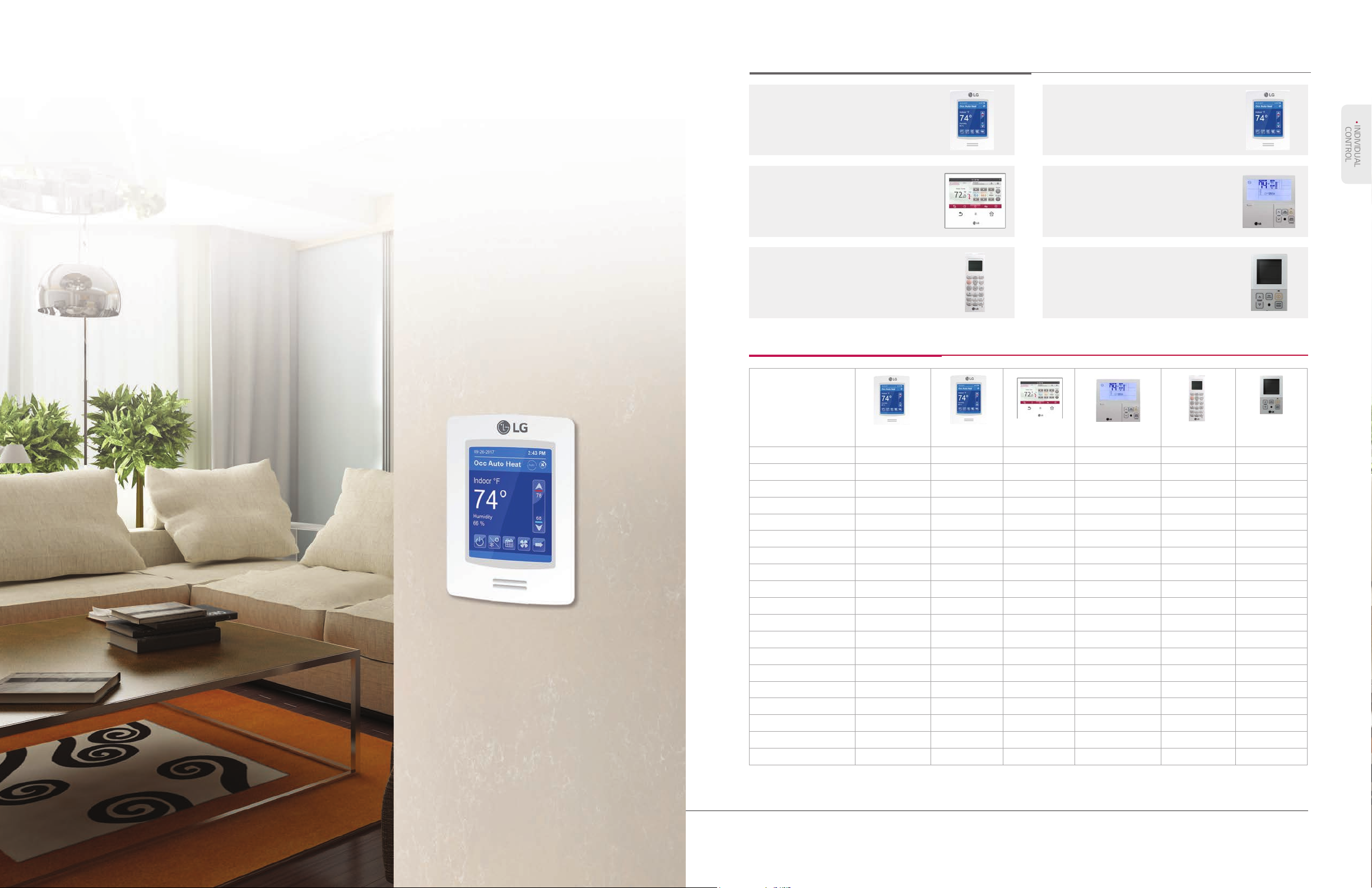
INDIVIDUAL CONTROLLERS
TECHNOLOGIES
INDIVIDUAL
CONTROLLERS
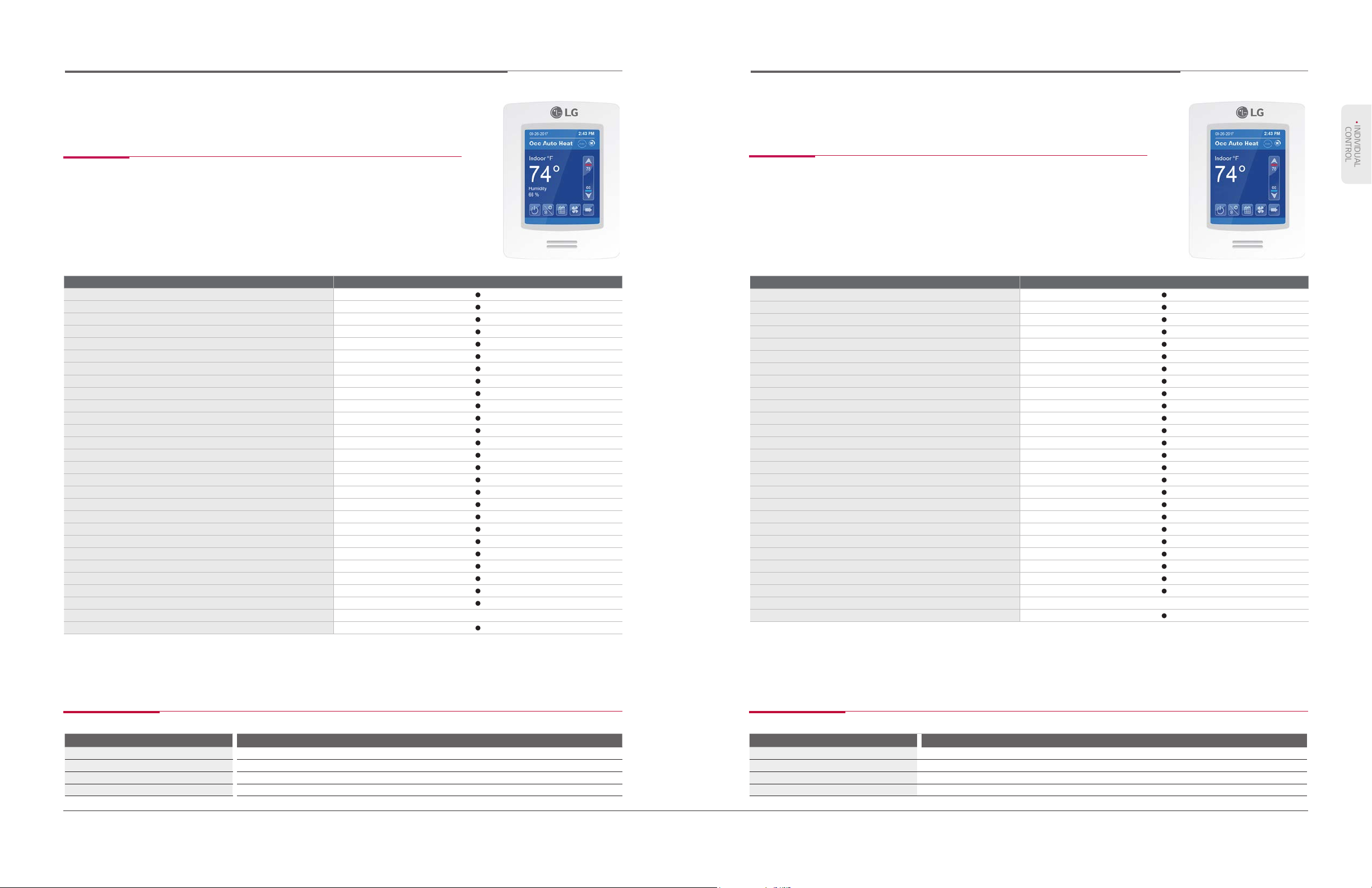
LG MultiSITE™ CRC1+
> Page 9
Premium Wired
Remote Controller
> Page 11
Wireless
Remote Controller
> Page 13
LG MultiSITE™ CRC1
> Page 10
Standard Wired
Remote Controller
> Page 12
Simple Wired
Remote Controller
> Page 13
Remote Controller Lineup
Model Name
PREMTBVC1 PREMTBVC0 PREMTA000
On / Off
Fan Speed Control
Temperature Setting
Mode Change
Additional Mode Setting
Auto Swing
Vane Control (Louver Direction)
E.S.P. (External Static Pressure)
Scheduling Weekly / Yearly Weekly / Yearly Weekly / Yearly
Child Lock
Settings Recovery
Time Display
Filter Sign
Energy Management**
Setback Two set points control Two set points control Two set points control - - -
On-Board Motion Sensor (PIR)
On-Board Humidity Sensor
ZigBee Wireless
BACnet MS/TP
* This feature is not available for PQRCHCA0QW
** A central controller and PDI are required for this function.
NOTE: Available functions/features may differ based on the connected system. Due to our commitment to continued innovation, some specications may be changed without notication.
• • • •
• • • •
• • • •
• • • •
• • • •
• • • •
• • • •
• • • •
• • • •
• • • •
• • • • •
Time Remaining &
Alarm
Time Remaining &
Alarm
Time Remaining &
Alarm
• •
•
•
• •
• •
PREMTB10U
Simple / Sleep / On / Off /
Weekly / Holiday
•
PQWRHQ0FDB
• •
• •
• •
• •
• •
• •
•
-
Sleep, on / off -
-
-
- -
-
PQRCVCL0QW
PQRCVCL0Q
PQRCHCA0QW
*
-
•
•
*
•
-
•
LG Air Conditioning Technologies
7 8
Page 6
MULTISITE REMOTE CONTROLLER (CRC1+)
• INDIVIDUAL
CONTROL
MULTISITE REMOTE CONTROLLER (CRC1)
PREMTBVC1
Features
The MultiSITE CRC1+ Remote Controller is a part of the LG MultiSITE Controls Suite. Featuring a
customizable home screen with a highly intuitive user interface, the MultiSITE CRC1+ Remote Controller
allows customers to tailor the functions and appearance to meet the needs of their application.
In addition to the flexibility of the user interface, the CRC1+ Remote Controller allows integration to a
Building Management System via its onboard BACnet® MS/TP connectivity. The touch screen, built in
Occupancy and Humidity sensor coupled with Zigbee wireless compatibility provides a complete out of the
box solution.
Model Name PREMTBVC1
BACnet MS/TP
ZigBee Pro Wireless Network
Motion (PIR) Sensor
Humidity Display
Function Code Search Tool
Congurable Home Screen
Screen Saver
On / Off
Fan Speed Control
Temperature Setting
Mode Change
Additional Mode Setting
Auto Swing
Vane Control (Louver Direction)
E.S.P. (External Static Pressure)
Scheduling
Digital Color Display
Indoor Temperature Display
Time Display
Date Display
Occupancy Status
Multilanguage Support
Electric Failure Compensation
Child Lock
Filter Sign Time Remaining & Alarm
Operation Status LED
Dimensions WxHxD (in) 3.39 x 4.72 x 1.06
Backlight
PREMTBVC0
Features
The MultiSITE CRC1+ Remote Controller is a part of the LG MultiSITE Controls Suite. Featuring a
customizable home screen with a highly intuitive user interface, the MultiSITE CRC1+ Remote Controller
allows customers to tailor the functions and appearance to meet the needs of their application.
In addition to the flexibility of the user interface, the CRC1+ Remote Controller allows integration to a
Building Management System via its onboard BACnet® MS/TP connectivity. The touch screen, coupled
with Zigbee wireless compatibility provides a complete out of the box solution.
Model Name PREMTA000
BACnet MS/TP
ZigBee Pro Wireless Network
Function Code Search Tool
Congurable Home Screen
Screen Saver
On / Off
Fan Speed Control
Temperature Setting
Mode Change
Additional Mode Setting
Auto Swing
Vane Control (Louver Direction)
E.S.P. (External Static Pressure)
Scheduling
Digital Color Display
Indoor Temperature Display
Time Display
Date Display
Occupancy Status
Multilanguage Support
Electric Failure Compensation
Child Lock
Filter Sign Time Remaining & Alarm
Energy Management
Operation Status LED
Dimensions WxHxD (in) 3.39 x 4.72 x 1.06
Backlight
NOTE: Available functions/features may differ based on the connected system. Due to our commitment to continued innovation, some specications may be changed without notication.NOTE: Available functions/features may differ based on the connected system. Due to our commitment to continued innovation, some specications may be changed without notication.
Accessories Accessories
Description
ZigBee Pro Wireless Card
Wireless Door & Window Switch ZVRCZDWS1
Wireless Ceiling Mounted Occupancy Sensor ZVRCZWOC1
Wireless Wall Mounted Occupancy Sensor ZVRCZCOC1
LG Air Conditioning Technologies
9 10
Model
ZVRCZPWC1
Description
ZigBee Pro Wireless Card
Wireless Door & Window Switch ZVRCZDWS1
Wireless Ceiling Mounted Occupancy Sensor ZVRCZWOC1
Wireless Wall Mounted Occupancy Sensor ZVRCZCOC1
Model
ZVRCZPWC1
Page 7
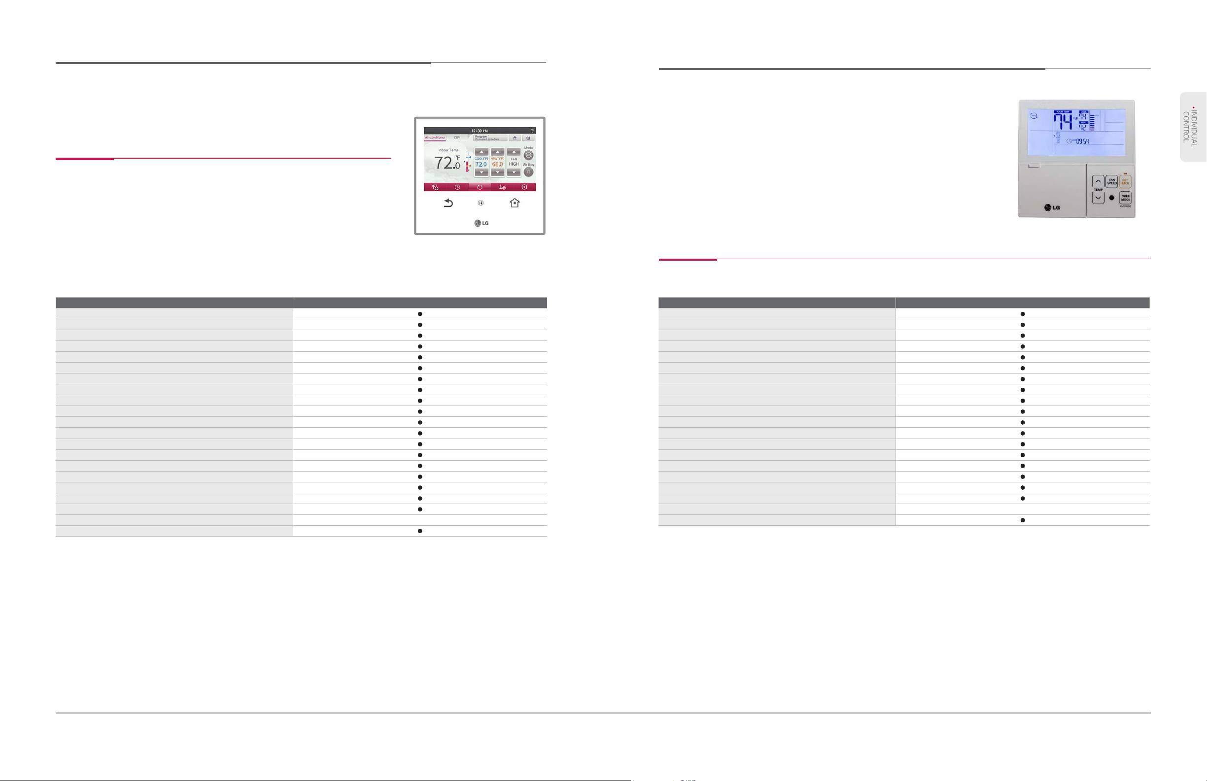
PREMIUM WIRED REMOTE CONTROLLER
• INDIVIDUAL
CONTROL
STANDARD WIRED REMOTE CONTROLLER
PREMTA000
Features
• Designed to optimize user experience
- Full touch/Intuitive GUI (graphical user interface)
- Main display simple mode/Touch buzzer
• Two set points control
• Improved scheduling
- Timer/Daily/Weekly/Yearly/Holiday
Model Name PREMTA000
On / Off
Fan Speed Control
Temperature Setting
Mode Change
Additional Mode Setting
Auto Swing
Vane Control (Louver Direction)
E.S.P. (External Static Pressure)
Scheduling
Digital Color Display
Indoor Temperature Display
Time Display
Occupancy Status
Electric Failure Compensation
Child Lock
Filter Sign Time Remaining & Alarm
Energy Management
Operation Status LED
Wireless Remote Controller Receiver
Dimensions WxHxD (in) 5-1/2 x 4-3/4 x 3/4
Backlight
• Self-management for energy saving
- Time limit operation/Power consumption
monitoring
- Weekly/Monthly/Yearly trend tracking
- Target alert alarm
- Temperature range setting
PREMTB10U
Features
Model Name PREMTA000
On / Off
Fan Speed Control
Temperature Setting
Mode Change
Additional Mode Setting
Auto Swing
Vane Control (Louver Direction)
E.S.P. (External Static Pressure)
Scheduling
Indoor Temperature Display
Time Display
Date Display
Occupancy Status
Electric Failure Compensation
Child Lock
Filter Sign Time Remaining & Alarm
Energy Management
Operation Status LED
Dimensions WxHxD (in) 4-3/4 x 4-3/4 x 5/8
Backlight
** A central controller and PDI are required for this function.
NOTE: Available functions/features may differ based on the connected system. Due to our commitment to continued innovation, some specications may be changed without notication.
LG Air Conditioning Technologies
11 12
NOTE: Available functions/features may differ based on the connected system. Due to our commitment to continued innovation, some specications may be changed without notication.
Page 8

SIMPLE WIRED REMOTE CONTROLLER
AIR CONDITIONING
With Mode Selection Without Mode Selection
PQRCVCL0QW
(White)
PQRCVCL0Q
(Black)
PQRCHCA0QW
(White)
Features
Model Name PQRCVCL0QW / PQRCVCL0Q PQRCHCA0QW / PQRCHCA0Q
On / Off
Fan Speed Control
Temperature Setting
Mode Change
Auto Swing
Vane Control (Louver Direction)
E.S.P. (External Static Pressure)
Child Lock
Wireless Remote Controller Receiver
Dimensions WxHxD (in) 2-3/4 x 4-3/4 x 5/8 2-3/4 x 4-3/4 x 5/8
NOTE: Available functions/features may differ based on the connected system. Due to our commitment to continued innovation, some specications may be changed without notication.
TECHNOLOGIES
CENTRAL
CONTROLLERS
WIRELESS REMOTE CONTROLLER
PQWRHQ0FDB
Features
Model Name PQWRHQ0FDB
On / Off
Fan Speed Control
Temperature Setting
Mode Change
Additional Mode Setting
Auto Swing
Vane Control (Louver Direction)
Scheduling
Indoor Temperature Display
Dimensions WxHxD (in) 2-3/16 x 1-3/16 x 6-3/16
NOTE: Available functions/features may differ based on the connected system. Due to our commitment to continued innovation, some specications may be changed without notication.
LG Air Conditioning Technologies
13 14
Page 9

CENTRAL CONTROLLERS
• CENTRAL
CONTROLLERS
AC SMART IV
Large 10.2 inch touch screen with intuitive GUI (Graphic User Interface) for easy system control.
AC Smart IV
> Page 15
ACP IV
> Page 17
Central Controller Lineup
Model Name
PACS4B000
Maximum Number of Indoor Units 128 256
Individual / Group Control
(On/Off, Mode, Set Point, Fan Speed)
Ventilation Control
Individual Controller Lock
Error Check
Schedule
Operation History
Visual Navigation
Operation Time Limit
Temperature Limit
Internet Access
Auto Changeover/Setback
Power Consumption Monitoring (with PDI)
Interlock Control
Virtual Group Control
Emergency Pattern Display
IO Module Interlocking
1)
An IP address is required to access the central controller through the internet.
NOTE: Available functions/features may differ based on the connected system. Due to our commitment to continued innovation, some specications may be changed without
notication.
1)
PACP4B001
PACS4B000
Features
Model Name
Maximum Number of Indoor Units
Individual / Group Control
Ventilation Control
Individual Controller Lock (Temperature / Mode / Fan / All)
Error Check
Mode Change
Schedule
Operation History
Visual Navigation
Operation Time Limit
Temperature Limit
Internet Access
Auto Changeover / Setback
Power Consumption Monitoring (with PDI)
Interlock Control
Virtual Group Control
Emergency Alarm Display
IO Module Interlocking
External IO Port No.
Dimensions WxHxD (in)
Weight
1)
An IP address is required to access the central controller through the internet.
NOTE: Available functions/features may differ based on the connected system. Due to our commitment to continued innovation, some specications may be changed without notication.
1)
Cooling / Heating / Auto / Dehumidication / Fan
Daily / Weekly / Monthly / Yearly / Exception Day
System Communication Architecture
CH1
CH2
PQCS4B000
Up to 128
Self Diagnosis
(Two set)
DI 2 / DO 2
10 x 6-5/8 x 1-3/16
TM
MULTI VTM WATER IV
5
MULTI V
MULTI V
TM
WATER Mini
Internet
LG Air Conditioning Technologies
15 16
MULTI V
TM
S
MULTI F
TM
SPACE II
MULTI F MAX
SINGLE ZONE
Requires the appropriate PI-485. Check the product's engineering manual for details.
ERV
DOASMULTI V
Page 10

AC SMART IV
• CENTRAL
CONTROLLERS
Functions
ACP IV (ADVANCED CONTROL PLATFORM)
PACP4B001
Features
Schedule
You can set a schedule for system air conditioner in advance for
timed events. Optimize system performance by enabling system
operation only as needed from centralized control management.
Energy Statistics (with PQNUD1S41 or PPWRDB000)
Statistics of operational status (time and energy management)
are provided to help make intelligent system operation decisions.
Visual Navigation
Provides one view of the system's operation status for the
building's oor plan.
Operation Report
A report including control status and other information is provided
to allow for operation history review. Data can be sent by e-mail or
stored externally via USB.
Model Name
Maximum Number of Indoor Units Up to 256
Individual / Group Control
Ventilation Control
Individual Controller Lock
Error Check
Mode Change Cooling / Heating / Auto / Dehumidication / Fan
Schedule Daily / Weekly / Monthly / Yearly / Exception Day
Operation History
Visual Navigation
Operation Time Limit
Temperature Limit
Internet Access
Auto Changeover / Setback (Two set)
Power Consumption Monitoring (with PDI)
Interlock Control
Virtual Group Control
Emergency Alarm Display
IO Module Interlocking
External IO Port No. DI 10 / DO 4
Dimensions WxHxD (in)
Weight
1)
An IP address is required to access the central controller through the internet.
NOTE: Available functions/features may differ based on the connected system. Due to our commitment to continued innovation, some specications may be changed without notication.
1)
PACP4B001
(Temperature / Mode / Fan / All)
Self Diagnosis
10-11/16 x 6-3/16 x 2-5/8
System Communication Architecture
CH1~4
Internet
MULTI V 5
Interlocking
Allows interlocked operation of devices or between digital inputs
and outputs on the AC Smart IV.
LG Air Conditioning Technologies
17 18
Emergency Display
The entire display will show a red alert in an emergency situation
while all other control signals are disabled.
MULTI V WATER IV
MULTI V WATER MINI
MULTI V S
MULTI V SPACE II
MULTI F
MULTI F MAX
SINGLE ZONE
Requires the appropriate PI-485. Check the product's engineering manual for details.
ERV
Page 11

SYSTEM INTEGRATION DEVICES
PBACNA000
AC Smart IV BACnet
PLNWKB100
ACP LonWorks
PQNFB17C2
ACP IV BACnet
On/Off Command
On/Off Status
Operation Mode Setting
Operation Mode Status
Fan Speed Setting
Fan Speed Status
Lock Setting
Lock Status
Air Flow Setting
Air Flow Status
Set Temperature Setting
Set Temperature Status
-
Current Space Temperature Status
-
Error Status
User Mode Setting (for only ERV)
User Mode Status (for only ERV)
• CENTRAL
CONTROLLERS
p
GATEWAY APPLICATION CONTROLLERS
MultiSITE Communications Manager
Dry Contact for Thermostat
MULTISITE COMMUNICATIONS MANAGER
PBACNBTR0A
The MultiSITE Communications Manager is a compact and powerful
controller that allows Third party integration of an LG HVAC system
into any Building Management System via BACnet, LonWorks and Fox
protocols. The MultiSITE Communications Manager is a network-ready,
out-of-the-box integration solution and includes the LG pre-engineered,
graphical user interface. The MultiSITE Communications Manager is
easily congurable and requires no additional software.
Features
PBACNBTR0A
PDRYCB300
Dry Contact for Economizer
PQDSBC1
Simple Dry Contact
PDRYCB100
PDI
(Power Distribution Indicator)
Premium (8 port)
PQNUD1S41
Standard (2 port)
PPWRDB000
• Integrates Multi V, MultI F, and select single zone systems
with third-party building management systems using BACnet,
LonWorks and Fox protocols
Operation Mode Setting Operation Mode Status
• Controls up to 128 indoor units
• Provides graphical user interface that allows centralized control
Temperature setpoint Temperature setpoint status
Upper Limit Temp. Setting Upper Limit Temperature Status
Low Limit Temp. Setting Low Limit Temperature Status
AC Operation Mode Setting AC Operation Mode Status
AC On/Off Command AC On/Off Status
Occupied/Unoccupied Occupied/Unoccupied
Dual Temperature Setpoint Setting Dual Temperature Setpoint Status
NOTE: Available functions/features may differ based on the connected system.
Due to our commitment to continued innovation, some specications may be changed without notication.
Accessories
Description Model
LON Module ZHWLONWK0
Wall Power Adapter ZHWPWADTR
System Communication Architecture
Controlling Monitoring Items
Control Monitor
On/Off Command On/Off Status
Fan Speed Setting Fan Speed Status
Lock Setting Lock Status
Air Flow Setting Air Flow Status
Current Space Temperature Status
Error Status
User Mode Setting User Mode Status
Accumulator Power Distribution Status
Mode Lock Setting Mode Lock Status
2SetAuto
Override
OccSensor
2SetAuto
OccSensorInstalled
2SetFuncSupport
IO MODULE
(Input / Output Module)
TM
MULTI VTM WATER IV
5
MULTI V
PEXPMB000
MULTI V
TM
WATER Mini
Internet
LG Air Conditioning Technologies
19 20
MULTI V
owered by
TM
S
TM
SPACE II
framework
MULTI F
MULTI F MAX
SINGLE ZONE
Requires the appropriate PI-485. Check the product's engineering manual for details.
BACnet® is a registered trademark of ASHRAE
®
LonWorks® is a registered trademark of the Echelon Corporation
Niagara Framework® is a registered trademark of Tridium Inc.
ERV
DOASMULTI V
Page 12

AC SMART IV BACNET GATEWAY
On/Off Command
On/Off Status
Operation Mode Setting
Operation Mode Status
Fan Speed Setting
Fan Speed Status
Lock Setting
Lock Status
Air Flow Setting
Air Flow Status
Set Temperature Setting
Set Temperature Status
-
Current Space Temperature Status
-
Error Status
User Mode Setting (for only ERV)
User Mode Status (for only ERV)
-
Accumulator Power Distribution Status
Upper Limit Temp. Setting
Upper Limit Temperature Status
Low Limit Temp. Setting
Low Limit Temperature Status
Mode Lock Setting
Mode Lock Status
AC Operation Mode Setting (ERV DX only)
Air Conditioner Operation Mode Status
(ERV DX only)
AC On/Off Command (ERV DX only)
Air Conditioner On/Off Status
(ERV DX only)
• CENTRAL
CONTROLLERS
ACP IV BACNET GATEWAY
PBACNA000
Features
• Controls up to 128 indoor units
• Controls up to 16 AHU Control kits
• Provides graphical user interface that allows centralized control
• BTL Listed (B-ASC)
• Integrates Multi V and select Mini and Multi Split systems with
third-party building management systems using a large 10.2-inch
touch screen with intuitive GUI (graphical user interface).
Dimensions (W X H X D): 10" x 6-5/8" x 1-3/16"
NOTE: Available functions/features may differ based on the connected system. Due to our commitment to
continued innovation, some specications may be changed without notication.
Controlling Monitoring Items
Controlling Monitoring Items
On/Off Command On/Off Status
Operation Mode Setting Operation Mode Status
Fan Speed Setting Fan Speed Status
Lock Setting Lock Status
Air Flow Setting Air Flow Status
Temperature setpoint Temperature setpoint status
- Current Space Temperature Status
- Error Status
User Mode Setting User Mode Status
- Accumulator Power Distribution Status
Upper Limit Temp. Setting Upper Limit Temperature Status
Low Limit Temp. Setting Low Limit Temperature Status
Mode Lock Setting Mode Lock Status
AC Operation Mode Setting AC Operation Mode Status
AC On/Off Command AC On/Off Status
Occupied/Unoccupied Occupied/Unoccupied
Dual Temperature Setpoint Setting Dual Temperature Setpoint Status
PQNFB17C2
Features
• Controls up to 256 indoor units
• Controls up to 16 AHU Control kits
• Provides graphical user interface that allows centralized control
• BTL Listed (B-ASC)
Dimensions (W X H X D): 10-11/16" x 6-3/16" x 2-5/8"
NOTE: Available functions/features may differ based on the connected system.
Due to our commitment to continued innovation, some specications may be changed without notication.
Controlling Monitoring Items
On/Off Command On/Off Status
Operation Mode Setting Operation Mode Status
Fan Speed Setting Fan Speed Status
Lock Setting Lock Status
Air Flow Setting Air Flow Status
Temperature setpoint Temperature setpoint status
- Current Space Temperature Status
- Error Status
User Mode Setting User Mode Status
- Accumulator Power Distribution Status
Upper Limit Temp. Setting Upper Limit Temperature Status
Low Limit Temp. Setting Low Limit Temperature Status
Mode Lock Setting Mode Lock Status
AC Operation Mode Setting AC Operation Mode Status
AC On/Off Command AC On/Off Status
Occupied/Unoccupied Occupied/Unoccupied
Dual Temperature Setpoint Setting Dual Temperature Setpoint Setting
System Communication Architecture
Lighting Control
Remote Monitoring
BMS system
CH1~2
1)
Internet
Indoor unit : Max. 128 units (Air conditioner & Ventilation) / Indoor address : 00 ~ FF
MULTI V 5
MULTI V WATER IV
MULTI V WATER MINI
MULTI V S
MULTI V SPACE II
MULTI F
MULTI F MAX
SINGLE ZONE
ERV
AC Smart
Requires the appropriate PI-485. Check the product's engineering manual for details.
1) Assignment of an IP address is required to access central controller through the Internet.
BACnet® is a registered trademark of ASHRAE
LG Air Conditioning Technologies
21 22
Power Monitoring
System Communication Architecture
BMS system
CH1~4
1)
Internet
ACP User Interface
Indoor unit : Max. 256 units (Air conditioner & Ventilation) / Indoor address : 00 ~ FF
MULTI V 5
MULTI V WATER IV
MULTI V WATER MINI
1) Assignment of an IP address is required to access central controller through the Internet.
BACnet® is a registered trademark of ASHRAE
Lighting Control
MULTI V S
MULTI V SPACE II
Requires the appropriate PI-485. Check the product's engineering manual for details.
Remote Monitoring
MULTI F
MULTI F MAX
SINGLE ZONE
ERV
Power Monitoring
Page 13

ACP LONWORKS GATEWAY
• CENTRAL
CONTROLLERS
I/O MODULE (INPUT/OUTPUT MODULE)
PLNWKB100
Features
Integrates Multi V, Multi F, and select single zone systems with third
party building management systems.
• Controls up to 64 indoor units
• Controls up to 16 AHU Control kits
• Provides graphical user interface that allows centralized control
• LonMark Certified
Dimensions (W X H X D): 10-11/16" x 6-3/16" x 2-5/8"
NOTE: Available functions/features may differ based on the connected system.
Due to our commitment to continued innovation, some specications may be changed without notication.
Controlling Monitoring Items
On / Off Command On / Off Status
Operation Mode Setting Operation Mode Status
Fan Speed Setting Fan Speed Status
Lock Setting Lock Status
Air Flow Setting Air Flow Status
Set Temperature Setting Set Temperature Status
- Current Space Temperature Status
- Error Status
- Accumulator Power Distribution Status
Upper Limit Temp. Setting Upper Limit Temperature Status
Low Limit Temp. Setting Low Limit Temperature Status
Mode Lock Setting Mode Lock Status
Peak Operation Ratio Setting Peak Operation Ratio Status
All On / Off Setting -
- Total Accumulated Power Status
PEXPMB000
Features
Model Name PEXPMB000
Linkable Products
Communication
I/O
Number of Indoor Units
Max. I/O Points
Maximum Number of Node
* Maximum number of Indoor units may be reduced by increasing the number of I/O points.
NOTE: Available functions/features may differ based on the connected system. Due to our commitment to continued innovation, some specications may be changed without notication.
RS-485
DI
DO
UI
AO
AC Smart IV ACP IV
64~128 128~256
130 224
9 16
AC Smart IV
ACP IV
1
3
3
4
4
Analog Input
Analog Output
Digital Input
Digital Output
• Dimensions-
• Weight-
Interface Type Min. Max.
NTC 10k
PT 1000
Ni 1000
DC (Voltage)
DC (Current)
- 0V 10V
Binary Input
(Dry Contact)
Normal open
0.68k
Ω
803k
Ω
871.7k
Ω
0V 10V
0mA 20mA
- -
- 30VAC / 30VDC, 2A
1675.2k
177k
1573k
Ω
Ω
Ω
System Communication Architecture
Lighting Control
Remote Monitoring
BMS system
CH1~4
1)
Internet
ACP User Interface
LG Air Conditioning Technologies
23 24
Indoor unit : Max. 64 units (Air conditioner & Ventilation) / Indoor address : 00 ~ FF
MULTI V 5 MULTI F
MULTI V WATER IV
MULTI V WATER MINI
MULTI V S
MULTI V SPACE II
Requires the appropriate PI-485. Check the product's engineering manual for details.
1) Assignment of an IP address is required to access central controller through the Internet.
Lonworks is a registered trademark of the Echelon Corporation.
MULTI F MAX
SINGLE ZONE
ERV
Power Monitoring
System Communication Architecture
AC Smart IV or ACP IV
NOTE: For a full list of compatible features, check the latest Engineering Manual.
PUMP DDC
• Sensor / Valve / Actuator
• Pump / Fan etc.
Fan AlarmLightingSecurity
Page 14

PDI PREMIUM (POWER DISTRIBUTION INDICATOR)
Premium
AIR CONDITIONING
TECHNOLOGIES
PQNUD1S41
Standard
PPWRDB000
(8 port)
(2 port)
Features
• Power monitoring data is backed up in the event of a power outage
• Connector can be separated for convenient installation
• Linkable with RS485 communication type or pulse type power meter
• Shows power consumption of up to 128 indoor units.
NOTE: Available functions/features may differ based on the connected system. Due to our commitment to continued innovation, some specications may be changed without notication.
ACCESSORIES
System Communication Architecture
Power Monitoring
Power In
LG Air Conditioning Technologies
25 26
Field Supplied
Power In for Indoor Units
Pulse Signal
RS485
(LGAP)
ACP IV
ACP IV BACnet ACP LonWorks
AC Smart IV
or
Power In
Page 15

ACCESSORIES
• ACCESSORIES
Lineup
DRY CONTACT
Simple Dry Contact
CONTROL ACCESSORY
Remote Temperature
Button Sensor
ZRTBS01
Group Control Wire
PZCWRCG3
Extension Cable
WATER SOURCE
SYSTEM
Variable Water
Flow Control Kit
PWFCKN000
Variable Water
Flow Control Kit
PRVC1
AIR SOURCE SYSTEM AHU KIT ERV
Low Ambient Kit
PRVC2
Cool/Heat
Selector
PRDSBM
Communication Kit
PRCKAM
Communication Kit
PRDCAM
EEV Kit (Electronic
Expansion Valve Kit)
CO2 sensor
PES-C0RV0
PI-485
PSNFP14A0
PDRYCB100
Features
Model Name PDRYCB100
Contact Point One Contact Point
Power Input AC 24V
Voltage / Non Voltage Input -
On / Off Control
Lock / Unlock -
Thermo Off -
Energy Saving -
Temperature Setting -
Error Monitoring
Operation Monitoring
Dimensions W x H x D (in) 4-1/8" x 3-1/16" x 1-3/8"
* Maximum operation AC : 3A
NOTE: Available functions/features may differ based on the connected system. Due to our commitment to continued innovation, some specications may be changed without notication.
PZCWRC1
PRLK048A0 /
PRLK096A
System Communication Architecture
CN-CC
Dry contact
LG Air Conditioning Technologies
27 28
Key Switch
Lighting
Sensor
Timer Occupancy Sensor Door Check Sensor
System Structure
Page 16

DRY CONTACT
• ACCESSORIES
DRY CONTACT
Dry Contact for Economizer
PQDSBC1
Features
Model Name PQDSBC1
On / Off
Economizer
Occupied / Unoccupied
Remote Lock / Unlock
Compressor Stop
Dimensions W x H x D (in) 4-1/8" x 3-1/16" x 1-3/8"
* Maximum operation AC : 3A
NOTE: Available functions/features may differ based on the connected system. Due to our commitment to continued innovation, some specications may be changed without notication.
Dry Contact for Thermostat (5-12Vdc, 24Vac)
PDRYCB300
Features
Model Name PDRYCB300
Model Name
On / Off Control
Mode Control (Cool, Heat, Fan)
Fan Speed Setting (Low, Middle, High)
Thermo Off
Error Monitoring
Operation Monitoring
Rotary Switch 1 Operating Set Temperature Selection
Rotary Switch 2 Operating Logic Selection
Dimensions W x H x D (in) 4-1/8" x 3-1/16" x 1-3/8"
Power Input 24V AC
System Communication Architecture
CN-CC
Dry contact
Economizer*
*Not available through LG
* Maximum operation AC : 3A
NOTE: Available functions/features may differ based on the connected system. Due to our commitment to continued innovation, some specications may be changed without notication.
System Communication Architecture
3rd Party
CN-CC
Dry contact
Thermostat
3rd Party T-stat
24VAC
External Contact
Closure
LG Air Conditioning Technologies
29 30
Page 17

CABLES
• ACCESSORIES
REMOTE TEMPERATURE BUTTON SENSOR
PZCWRCG3
PZCWRC1
Features
Description Model Length (ft.)
Group Control Cable Kit PZCWRCG3 0.82
Extension Cable PZCWRC1 32.8
* Maximum operation AC : 3A
Connect up to 16 indoor units with the group control cable kit. Extend the control wire up to 32.8 ft with the extension cable.
NOTE: Available functions/features may differ based on the connected system. Due to our commitment to continued innovation, some specications may be changed without notication.
ZRTBS01
Features
• 0.8" Diameter (approximate size of a quarter) flush button mounts virtually anywhere
• Paintable with latex or oil base to match any decor
• Replaces IDU return air sensor for remote temperature sensing
• Connects to CN-ROOM on IDU PCB
• Compatible LG indoor units: All cassette and ducted IDUs for Multi V, Multi F, Multi F MAX, and Single Zone
• Applied to Ceiling Mounted Cassette, Ceiling Concealed Duct, and Hydro Kit
• Extension cable (49 ft) is included
• Dimensions-
• Weight-
NOTE: Available functions/features may differ based on the connected system. Due to our commitment to continued innovation, some specications may be changed without notication.
System Communication Architecture
Indoor 1 MAIN PCB
Indoor 1
Indoor terminal block
RED (12V)
YL (SIGNAL)
BK (GND)
Note : Group Control Cable Kit
1
2
Extension Cable
LG Air Conditioning Technologies
31 32
Indoor 2 Indoor 3
Indoor terminal block Indoor terminal block
YL (SIGNAL)
BK (GND)
YL (SIGNAL)
BK (GND)
System Communication Architecture
Extension cable
CN-ROOM
Remote Temperature
Button Sensor
Indoor Unit
Wired Remote
Controller
Page 18

LOW AMBIENT CONTROL KIT
• ACCESSORIES
VARIABLE WATER FLOW CONTROL KIT
External integration module for cooling operation with -9˚F low ambient temperature.
PRVC2
Features
FUNCTION
• -9˚F Low ambient cooling operation using Low ambient kit and hood with damper
(Analog output 0~10V)
• Demand control
DESCRIPTION
• Low ambient kit supports -9˚F cooling operation by making stable condensing
pressure with reducing air ow rate from hood and damper control given 0~10V
proportional to condensing pressure.
• Low ambient kit provides IO Module function.
• The appropriate Low Ambient Baffle Kit is a required accessory.
• Transformer and terminal block are included.
Front Back
Required accessory for controlling water ow when the entering water temperature is lower than 59°F.
PWFCKN000
PRVC1
Features
FUNCTION
• Water valve control (0~10V)
• Minimum output voltage setting available
• Operation, error output (250VAC, Max 1A)
• Dry contact input and analog output for demand control
• Digital output for operation, error status (250VAC, Max 1A)
ADVANTAGE
• Water ow consumption reduction
• Pump electricity consumption reduction
• Including IO Module (Dry contact input, Analog input/output, Digital output)
: Using Dry contact and variable water ow control function simultaneously
Models Applied
• MULTI V 5
Models Applied
• PWFCKN000 - Multi V Water IV
• PRVC1 - Multi V Water Mini
System Communication Architecture
Main PCB
Damper Actuator (0~10V)
Transformer
220VAC
-> 24VAC
MULTI V 5 IO Module
Common
NOTE : The IO Module can control maximum three actuators.
LG Air Conditioning Technologies
33 34
DC 0~10V
Control
Reference : Air Damper
24VAC
Wiring Diagram
0 ~ 10V (Analog output)
Flow
control
valve
Flow
control
valve
Field
supplied
Field
supplied
Pressure
sensor
Field
supplied
Water
Control Signal
Pump/Cooling
Tower Controller
Field
supplied
From Water Source
* Field Supplied
Page 19

AIR HANDLING UNIT (AHU) MODULES
Communication Kit
EEV Kit
• ACCESSORIES
Solution to extend the benets of LG VRF technology to third party Air Handling Units.
PRCKAM PRDCAM PRLK048A0
Specifications
Type
Communica-
tion Kit
NOTE: Available functions/features may differ based on the connected system. Due to our commitment to continued innovation, some specications may be changed without notication.
Model
Name
PRCKAM
PRDCAM
Outdoor
unit
MULTI V
MULTI V
Combination
EEV Kit
PRLK096A0
Expansion
Kit
Central
controller
-
Description
Return/room air by remote controller or dry contact
Return/room air or supply air (capacity) control by
DDC. This unit is connected with outdoor unit1:1
control
Dimensions (in)
W H D Weight
11-13/16 11-13/16 6-1/8
15-3/4 19-11/16 8-3/8
Function list for Communication Kit
List Description
Outdoor Unit Operation On/Off By wired controller*
Mode Fan only/heating/cooling
Fan Step High/mid/low (three steps)
Controlling
Room Temperature Control
Supply Air Temperature
(by outdoor capacity control)
Outdoor Unit Operation
AHU Communication Kit
Operation
Outdoor Mode
Monitoring
* Optional accessory, recommended model : PREMTB10U
** Binary input and output (Open and short), DO is normal open
Fan Mode
Error Status
Cooling 64 ~ 86
Compressor Off, Compressor Off & Fan Off,
o
F, Heating 60 ~ 86oF By wired controller* Analog input 0 V 10 V
40 ~ 100% capacity control
On/Off -
On/Off -
Fan/defrost/cooling/heating -
High/mid/low (three steps)
No error/error occurred
PRCKAM PRDCAM
Min Type Min Max
- Analog input 0 V 10 V
Specications
Type Model Name Description Capacity Range
EEV Kit
PRLK048A0
PRLK096A0
For MULTI V - In combination with or
without indoor units. Several EEV kits can
be connected to a single outdoor unit.
Specication
Digital input**
(Non-voltage)
Digital input
(Non-voltage)
Digital input
(Non-voltage)
Digital input**
(Non-voltage)
Digital input
(Non-voltage)
Digital input
(Non-voltage)
Digital input
(Non-voltage)
Digital input
(Non-voltage)
8 tons maximum 8-5/8 15-15/16 3-5/16
16 tons maximum 8-5/8 15-15/16 3-5/16
- -
- -
- -
Max : AC 250 V, DC 30 V, 1A
Max : AC 250 V, DC 30 V, 1A
Max : AC 250 V, DC 30 V, 1A
Max : AC 250 V, DC 30 V, 1A
Max : AC 250 V, DC 30 V, 1A
Dimensions (in)
W H D
Capacity Selection
For MULTI V
• When selecting evaporator, change ‘Option PCB’ in Communication kit
according to below table (Basic ‘Option PCB’ is for 36k Btu/h)
• After verifying the required capacity, remove the 36k Option PCB
equipped in the main PCB, and replace with the corresponding
Option PCB in the table to the right.
Detail
Option PCB P/No Capacity Index (Btu/h)
EBR52358907 28k
EBR52358908 36k
EBR52358909 42k
EBR52358910 48k
EBR52358911 76k
EBR52358912 96k
EBR52358914 115k
EBR52358915 134k
EBR52358916 153k
EBR52358917 172k
EBR52358913 192k
System Architecture
• MULTI V Application (in Combination with third-party AHU)
Refrigerant Piping
Communication Wire
*DDC : Digital Direct Controller
Sensor Signal
Return Air Exhaust Air Outdoor Air Supply Air
Comm. kit
PRCKAM
EEV kit
PRLK048A0 or
PRLK096A0
Dry contact
PDRYCB300
Field Supplied
*DDC
Capacity setting
(Main PCB)
LG Air Conditioning Technologies
35 36
'Option PCB'
Page 20

COOL/HEAT SELECTOR
• ACCESSORIES
ACCESSORIES FOR ERV
These accessories allow for additional functionality when using LG ERV systems.
PRDSBM
Features
• Provides a single location for choosing cooling, heating, or fan mode for the entire system.
• Mode lock for cooling & heating
Models Applied
• MULTI V 5
• MULTI V S
• MULTI V WATER IV
• MULTI V SPACE II
• MULTI V WATER MINI
NOTE: Available functions/features may differ based on the connected system. Due to our commitment to continued innovation, some specications may be changed without notication.
PSNFP14A0
PES-C0RV0
Features for PI-485
• Model Number: PSNFP14A0
• Power: Connected with the Indoor Units
• 1 for Each Indoor Unit
• Dimensions W x H x D (in.): 3-1/4 x 4-1/16 x 1-1/4
Features for CO
NOTE: Available functions/features may differ based on the connected system. Due to our commitment to continued innovation, some specications may be changed without notication.
Sensor
2
PES-C0RV0
The PES-C0RV0 is especially designed to work in conjunction with LG Energy Recovery Ventilators (ERVs). Real-time CO
detected and displayed on the sensor’s LCD. The PES=C0RV0 then sends the data to the LG ERV via the hard-wired connection
cable coupled with the supplied 33-foot extension cable. LG ERVs, using stand-alone embedded logic, will respond to CO
in the surrounding ambient air by applying demand control ventilation when its fan is set to Auto mode. Energy efciency is
increased, and indoor air quality can be improved when ventilation air is introduced to the monitored space only as necessary.
STANDARD FEATURES:
• Constant monitoring of CO
• LCD display readout
• LED sensor light indications for troubleshooting
• Direct attachment through a 33-foot cable
• Connects to CN_CC02 socket on ERV control board
levels
2
* Provided with a case to be installed on the exterior.
* A PI-485 is not required when used with Multi V systems.
levels are
2
changes
2
System Communication Architecture
Fan Mode
Cooling
only
LG Air Conditioning Technologies
37 38
Mode Change
Heating
only
Compatibility
ARVU053ZEA2 / ARVU063ZEA2
ARVU093ZFA2 / ARVU123ZFA2
• Compatible with ERV (Energy Recovery Ventilator):
ARVU053ZEA2
ARVU063ZEA2
ARVU093ZFA2
ARVU123ZFA2
Page 21

MECHANICAL ACCESSORIES
Suction Grille
Canvas
PRARH*
PRARS*
PBSGB30
/ PBSGB40
PBSC30 / PBSC40
Aux Heater Relay Kit
ZFBXB*01A
HSD Filter Box
PTVK410
PTVK420 PTVK430
Ventilation Kit
PTDCM
PTDCQ
Cassette Cover
4-Way Cassette
PT-UQC / PT-UMC1
4-Way Black Cassette
PT-UMC1B
2-Way Cassette
PT-HLC1
1-Way Cassette
PT-UUC1
PT-UTC
Cassette Panel
PTPKM0
PTPKQ0
Plasma Kit
PTEGM0
Auto Elevation Grille
PRHR022A
PRHR032A
PRHR042A
Heat Recovery Unit
ZHGDKA51A
ZHGDKA52A
ZLABKA51A
ZLABKA52A
Hail Guard
Low Ambient Bafe Kit
ZAGDKA51A
ZAGDKA52A
Air Guide
Air Guide
ZLABGP04A
Wind Bafe
4-Way True 2x2 Cassette
PT-QCHW0
• MECHANICAL
ACCESSORIES
Lineup
HEAT RECOVERY UNIT
INDOOR
Ceiling Mounted Cassette Ceiling Concealed Duct
Other
AIR TECHNOLOGIES
Air Cleaner
ZFBXD201A
ZFBXD402A
Air Cleaner Media
ZFLT1301A
ZFLT1302A
Return Air Grill
ZGRLRA01A
ZGRLRA02A
PRHR022A
PRHR032A
PRHR042A
PRHR022A
(2-branch Unit)
Features
• Max. 32 indoor units can be connected (Max eight indoor units per branch)
• Easy installation with auto pipe detect
• Delivers maximum efciency using the subcooling cycle within the HR Unit
Models Applied
• MULTI V 5 Heat Recovery
• MULTI V WATER IV Heat Recovery
• Multi V S Heat Recovery
Specifications
PRHR032A
(3-branch Unit)
PRHR042A
(4-branch Unit)
39 40
LG Air Conditioning Technologies
Return Air Plenum
ZPLMV201A
ZPLMV402A
OUTDOOR MULTI V
Specication Unit PRHR022A PRHR032A PRHR042A
2
Number of Indoor Unit Ports
Power Input Watts 26 40 40
Max Port Capacity Each Port Btu/h 54,000 54,000 54,000
Electrical Power Supply (V/Hz/Ø 208-230/60/1 208-230/60/1 208-230/60/1
Piping Port Liquid Line in 3/8 3/8 3/8
Sound Pressure Data Cooling Mode dB(A) 35.2 35.2 35.2
Weight Net Unit Weight lbs 40 45 49
Dimensions W x D x H in 17-7/8 x 18-15/16 x 8-5/8 17-7/8 x 18-15/16 x 8-5/8 17-7/8 x 18-15/16 x 8-5/8
1. All refrigerant pipes require insulation.
2. Each port can allow up to eight indoor units with a maximum capacity of 48k Btu/h per port.
3. All communication cable to be minimum 18 AWG, 2-conductor, stranded, shielded and must comply with applicable local and national code.
4. Kit components must be kept dry and free of debris before installation.
5. Must follow installation instructions in the applicable LG installation manual.
6. Power wiring cable size must comply with the applicable local and national code.
7. This unit comes with a dry nitrogen charge.
8. Due to our commitment to continued innovation, some specications may be changed without notication.
Model Name
Sum of Ports Btu/h 192,000 192,000 192,000
Rated Amps A 0.08 0.12 0.16
Port Vapor Line in 5/8 5/8 5/8
System Liquid Line in 3/8 1/2 5/8
System Vapor Line High in 3/4 7/8 7/8
System Vapor Line Low in 7/8 1-1/8 1-1/8
Heating Mode dB(A) 35.1 35.1 35.1
Simultaneous dB(A) 43.3 43.3 43.3
Shipping Weight lbs 48 54 57
2 3 4
Page 22

PTDCM
PTDCQ
PTPKM0
PTPKQ0
PTVK410
PTVK420
PBSGB30
PBSGB40
PBSC30
PBSC40
ACCESSORIES
• MECHANICAL
ACCESSORIES
ZHGDKA51A
ZHGDKA52A
ZLABKA51A
ZLABKA52A
ZLABGP04A
(for use with Multi V S)
Hail Guard
Low Ambient Baffle Kit
Wind Baffle
ZAGDKA51A
ZAGDKA52A
Air Guide
Air Guide
Indoor Accessories
ACCESSORIES
Outdoor Accessories
PTEGM0 PT-UUC1
PT-UMC1BPT-QCHW0
PT-UMC1
ZFLT1301A
ZFLT1302A
PT-HLC1PT-UQC
PRARH0
PRARH1
PT-UTC
PSNFP14A0
CO2 Sensor HSD Filter BoxPTVK430
PRARS1
Unit Type Category Model Description Used with
Cassette Auto Elevation Kit PTEGM0 Auto Elevation Grill Kit TP, TN, TM
Cassette Cover
Cassette Panel
Ceiling Cassettes
Cassette Ventilation
Plasma Kit
HSD Filter Box
High Static
Ducted &
Outside Air Unit
LSD Bottom Return
Vertical AHU Heat Kit
Auxiliary Heat Kit
Air Cleaner
Air Cleaner Media
Return Air Plenum
LSD Bottom Return Canvas
LSD Bottom Return Grille
PTDCM
PTDCQ TQ, TR
PT-UTC 1-Way Ceiling Cassette Panel TT
PT-UUC1 1-Way Ceiling Cassette Panel TU
PT-HLC1 2-Way Ceiling Cassette Panel TL
PT-UQC 4-Way Ceiling Cassette Panel TQ, TR
PT-QCHW0 4-Way Ceiling Cassette Panel, True 2x2 TQ, TR
PT-UMC1 4-Way Ceiling Cassette Panel TP, TN, TM
PT-UMC1B 4-Way Ceiling Cassette Panel, Black TP, TN, TM
PTVK410 Ventilation Air Intake Spacer for 4-Way Ceiling Cassette (Requires PTVK420) TP, TN, TM
PTVK420 6” Ø Ventilation Air Connection Flange for 4-Way Ceiling Cassette TP, TN, TM
PTVK430 3” Ø Ventilation Air Connection Flange for 4-Way Ceiling Cassette TQ, TR, TP, TN, TM
PTPKM0 4-Way Ceiling Cassette Plasma Kit (3x3) TP, TN, TM
PTPKQ0 4-Way Ceiling Cassette Plasma Kit (2x2) TQ, TR
ZFBXB801A High-Capacity Filter Box B8
ZFBXBG01A High-Capacity Filter Box BG
ZFBXBH01A High-Capacity Filter Box BH
ZFBXBR01A High-Capacity Filter Box BR
ZFBXD201A DYNAMIC V8-2VL Low-Prole Air Cleaner BG, BH, BR, B8
ZFBXD402A DYNAMIC V8-4VL Low-Prole Air Cleaner BG, BH, BR, B8
ZFLT1301A Air Cleaner Media 4-Pack BG, BH, BR, B8
ZFLT1302A Air Cleaner Media 24-Pack BG, BH, BR, B8
ZPLMV201A 2VL Return Air Plenum BG, BH, BR, B8
ZPLMV401A 4VL Return Air Plenum BG, BH, BR, B8
PBSC30 Return Air Canvas (Requires PBSGB30 Grille) B3
PBSC40 Return Air Canvas (Requires PBSGB40 Grille) B4
PBSGC30 Return Air Grille (Requires PBSC30 Canvas) B3
PBSGC40 Return Air Grille (Requires PBSC40 Canvas) B4
ANEH053B1 5kw Electric Heat Kit NJ, NK
ANEH103B2 10kw Electric Heat Kit NJ (243, 303, 363), NK
ANEH153B2 15kw Electric Heat Kit NK
ANEH203B2 20kw Electric Heat Kit NK
PRARH0 Auxiliary Heat Kit for Gen 2 Cassettes, Ducted, and Convertible units VJ, VE
PRARH1 Auxiliary Heat Kit for Gen 4 Cassettes, Ducted, and Convertible units
PRARS1 Auxiliar y Heat Kit for Wall Mounted Units SB, SC
Decorative Cover for 4-Way Ceiling Cassette
B3, B4, B8, BG, BH, BR, L1, L2, L3,
TL, TM, TN, TP, TQ, TR, TT, TU
TP, TN, TM
Type Model Description Used with
Air Guide
Hail Guard
Low Ambient Baffle Kit
Wind Baffle ZLABGP04A Low Ambient Baffle Kit (two required per unit) Multi V S
ZAGDKA51A Air Guide Multi V 5 (6 Ton Chassis)
ZAGDKA52A Air Guide Multi V 5 (8 to 20 Ton Chassis)
ZHGDKA51A Hail Guards Kit Multi V 5 (6 Ton Chassis)
ZHGDKA52A Hail Guards Kit Multi V 5 (8 to 20 Ton Chassis)
ZLABKA51A Low Ambient Baffle Kit (requires PRVC2) Multi V 5 (6 Ton Chassis)
ZLABKA52A Low Ambient Baffle Kit (requires PRVC2) Multi V 5 (8 to 20 Ton Chassis)
41 42
LG Air Conditioning Technologies
Page 23

framework
p
owered by
®
LG Electronics USA, Inc.
Distributed by
Air Conditioning Technologies
4300 North Point Parkway, Alpharetta, GA 30022
www.lghvac.com
Copyright © 2017 LG Electronics. All rights reserved.
LG Air Conditioning Technologies
43
Document Number: PC_MultiV_Controls_Accessories_01_17
 Loading...