

Page 1

LG
PC Central Controller
Installation Manual
LG
IMPORTANT
• Please read this Installation Manual carefully and
thoroughly before installing and operating your room air
conditioner.
• Please retain this Installation Manual for future reference
after reading it thoroughly.
Visit us at : http://www.lgservice.com
ENGLISH ITALIANO ESPAÑOL FRANÇAIS DEUTSCH
Page 2

2 PC Central Controller
PC Central Controller
TABLE OF CONTENTS
■ System Structure
................................................................................
3
• System Configuration.
......................................................................
3
■ External Wiring Diagram
...................................................................
4
• Multi-V CRU(N)N
.............................................................................
4
• Multi-V PLUS & MPS Product
..........................................................
5
■ Internal Wiring Diagram
...................................................................
6
• Multi-V CRU(N)N
.............................................................................
6
• Multi-V PLUS & MPS Product
..........................................................
7
■ Network Interface Connection
.........................................................
8
• P1485(M) Dip Switch Configuration
.................................................
8
• CNU Connection
...............................................................................
9
■ The Indoor Unit Address Setting method
........................................11
• Multi-V CRU(N)N
..........................................................................
11
• Multi-V PLUS & MPS Product
........................................................
12
■ Installation of PC Central Controller Hardware
...............................
14
• Parts of PC Central Controller .......................................................14
• Connection USB Hard_Lock key....................................................14
■ Installation of PC Central Controller Software
................................
15
• Recommended System Configuration ...........................................15
• How to install program....................................................................16
• Engine S/W Registration in service program .................................17
• Execution of the Program ...............................................................18
• How to use approval Hard_Lock ....................................................19
• System Set-Up................................................................................20
• Configuration of System Setting Screen........................................20
• How to search for IP which is set at the CNU (I-MODULE) ..........22
• IP Test Method (PING Test)............................................................26
• INSTALLATION OF WEB SERVER ...............................................27
Page 3
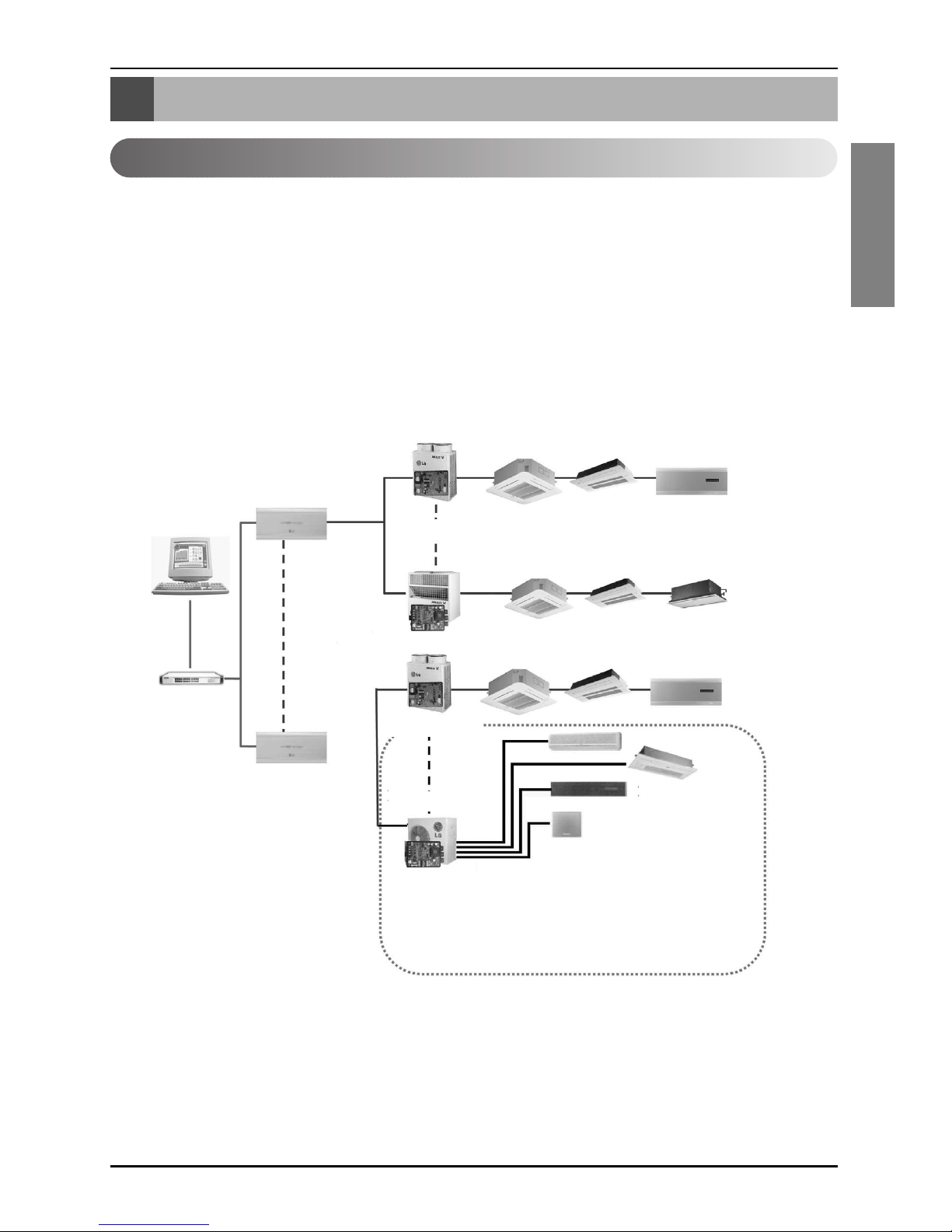
System Structure
Installation Manual 3
ENGLISH
System Structure
System Configuration
System Configuration
- 16 CNU / 1 PC Central Controller
-8PI485/1CNU
- 1Outdoor Unit / 1 PI485
•NOTE:If your requirement does not match above mentioned spec then Please Contact Airconditioner Department for support.
Multi V Outdoor Unit
1PC
Central Controller
PQNFP00A0
PMNFP14A0
PQNFP00A0
HUB
CNU(Interface)
LAN
MPS Outdoor
PMNFP14A0
70 71 7F
OF01
00
7C
7D
7F
F
1
00 01
0F
7E
Page 4
External Wiring Diagram
4 PC Central Controller
External Wiring Diagram
Multi V CRU(N)N
- Refer the wiring diagram and connect the communication line accordingly
A, B terminals are for connecting to Indoor units, and C, D terminals are for connecting to
CNU.
* Notice : Indoor unit address setting can be done by rotary switch in the Indoor unit PCB
Indoor units
00 01 02 0F
10 11 12 1F
F0 F1 F2 FF
LAN Port
CNU
(PQNFG00A0)
Cross
Cable
BUS A
BUS B
PI485
MAIN PCB
Outdoor unit 0
CC
AA
BB
D
VCC VCC
GND GND
D
PI485
MAIN PCB
Outdoor unit 1
CC
AA
BB
D
VCC VCC
GND GND
D
PI485
MAIN PCB
Outdoor unit 16
CC
AA
BB
D
VCC VCC
GND GND
D
PC Central Controller
Page 5
External Wiring Diagram
Installation Manual 5
ENGLISH
Multi-V PLUS & MPS Product
- Refer the wiring diagram and connect the communication line accordingly
A, B terminals are for connecting to Indoor units, and C, D terminals are for connecting to
CNU.
* Notice : Indoor unit address setting can be done by wired and wireless remote controller
Indoor units
00 01 02 0F
10 11 12 1F
F0 F1 F2 FF
LAN Port
CNU
(PQNFG00A0)
Cross
Cable
BUS A
BUS B
MAIN PCB
Outdoor unit 0
CC
AA
BB
D
VCC VCC
GND GND
D
EE
F
F
MAIN PCB
Outdoor unit 1
PI485
MAIN PCB
Outdoor unit 16
PI485
PI485
CC
AA
BB
D
VCC VCC
GND GND
D
EE
F
F
CC
AA
BB
D
VCC VCC
GND GND
D
EE
F
F
PC Central Controller
Page 6

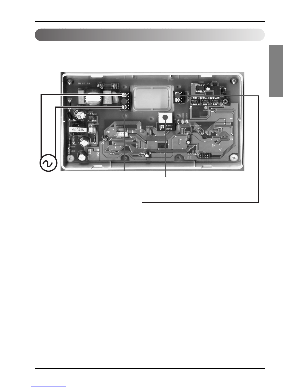
Internal Wiring Diagram
6 PC Central Controller
Internal Wiring Diagram
Multi V Terminal Block
ABCD
VCC GND
BUS_A
BUS_B
CNU
(PQNFG00A0)
Power terminal
AC 220~250 V 50/60Hz
LAN Port
PC Cental Controller
Multi V CRU(N)N
Outdoor Main PCB
CN_CENTRAL
Central Controller communication line
RS485 communication line
*Notice : CNU and PI485(PQNFP00A0, PQNFG00A0) should be purchased separately.
PI485
(PQNFP00A0)
Page 7
Internal Wiring Diagram
Installation Manual 7
ENGLISH
Multi V PLUS & MPS Product
ON
L1 2 3 4
KSDO4H
BUS_A
BUS_A
BUS_B
BUS_B
Multi V Terminal Block
ABEFCD
VCC GND
CN_CENTRAL
Please refer to Network Interface setting method
on the next page.
It explains about how to set PI485(M) DIP switch.
Outdoor Main PCB
CNU
(PQNFG00A0)
Power terminal
AC 220~250 V 50/60Hz
PMNFP14A0
LAN Port
RS485 communication line
PC Central Controller
Note : Terminal Block Use in case of Multi V and other models may Or may not be present.
If it is not present, make direct connections.
Page 8
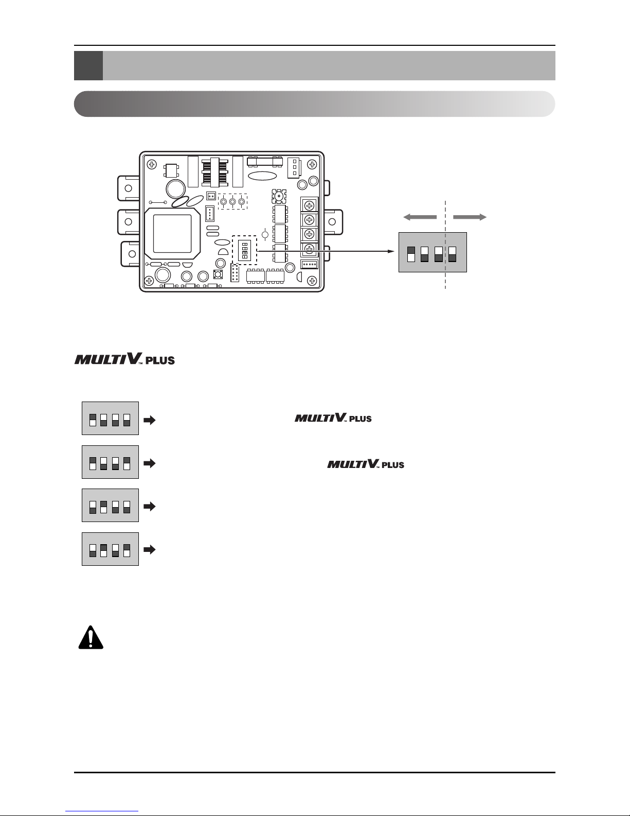
Network Interface Connection
8 PC Central Controller
Network Interface Connection
ON
L1 2 3 4
KSDO4H
ON KSDO 4H
P1485(M) Dip Switch Configuration
ON KSDO4H
ON KSDO4H
ON KSDO4H
ON KSDO4H
Select Air
Conditioner Type
Select Network
Type
* LGAP : LG Air conditioner Protocol
1 ON, All others OFF: & MPS
Inverter Product + Central Controller (All types) Without LGAP
1and4ON,AllothersOFF: &MPS
Inverter Product + Central Controller (All types) Using LGAP
2 ON, All others OFF: MPS Multi Standard Product + Central Controller
(All types) - Without LGAP
2 and 4 ON, All others OFF: Multi Standard Product + Central Controller
(All types) - Using LGAP
& MPS MULTI Products Configuration Methods
CAUTION:
The wrong setting of air-conditioner switch could cause malfunctioning.
Switch setting must be done carefully.
* Please refer the corresponding Central Controller installation manual if you want to know whether
your Central Controller is compatible with LGAP or not.
Page 9
Network Interface Connection
Installation Manual 9
ENGLISH
CNU Connection
CNU : Central Network Unit (PNFG00A0)
RJ45 Connector : Connect with HUB OR
Deluxe Central Controller
Power Terminal
AC 220~250 V 50/60Hz
RS-485 Communication Terminal
Connect with PNFP00A0 'C,D'
OR
Connect with PMNFP14A0 'A,B'
• NOTICE
PNFG00A0 ---- PNFP00A0 (PMNFP14A0)
BUS_A ---- BUS_C (BUS_A)
BUS_B ---- BUS_D (BUS_B)
Use two shield lines for RS-485 connecting line.
(Earth the shield line)
Page 10

Network Interface Connection
10 PC Central Controller
Wiring Diagram
Cross Cable
Direct Cable
Direct Cable
Direct Cable Connection Method
Cross Cable Connection Method
Cross Cable – Used for 1:1 connection between same equipment in the network.
Direct Cable - Also called as 1:1 straight cable and used for connecting
other equipment from the network.
* How to differentiate between Direct Cable & Cross Cable
The UTP cable consists of 8 stripes of wire and the wire actually used for data transmission in the
LAN environment is the reception (Rx) No.1 and 2 wire and the transmission (Tx) No.3 and 6,
consisting of 4 strands. They are classified into two types depending on method to connect wire for
reception and transmission.
Page 11

The Indoor Unit Address Setting method
Installation Manual 11
ENGLISH
The Indoor Unit Address Setting method
Multi-V CRU(N)N
The indoor unit PCB has 2 rotary switches.
Rotary High is for Group number setting and Rotary Low is for Room number setting.
The Group number of the rotary switch of the Central Controller and the Indoor unit PCB
rotary switch must match.
Example : Group number setting method(Central Controller Group rotary switch number 0 =
The Indoor unit PCB rotary switch Group number 0)
Example : The Indoor unit number setting method (the Indoor unit PCB rotary switch
number 1 = Central controller LED number 1 turns ON)
Rotary_low
Rotary_low
Rotary_high
Rotary_high
Indoor Unit number 1
On central control
Group number 1
On central control
Indoor Unit
No. setting
Group Unit
No. setting
Page 12

The Indoor Unit Address Setting method
12 PC Central Controller
Multi-V PLUS & MPS Product
■ Using wired remote controller
Timer Cancel
Program Week
Hour Min
Holiday
Set/Clr
RESET
ZONE
1234
Operation unit
Humidify
JET
AUTO
AUTO SWING OPERATION
FAN SPEED
Program set
SUB FUNCTION
SET TEMP
Room Temp
HI
MED
LO
Heater
Defrost
Filter
Preheat
Out door
Time
Timer
On
Set no. Time
Off
01 03 05 07 09 11 13 15 17 19 21 23
Plasma
Program
Set/Ctl
1. Press Program & Set/Clr keys at the same time.
2. Set the indoor unit address using the temperature controller.
Allowed Range : 00-FF
3. Complete the address setting to press the week Program & Set/Clr keys at the same time for 3
seconds.
❈ Some remote controllers may not be suported by above functions, a coording to the production date
of wired/wireless remote conrollers. As it has no concem with customers' use, use the remote
controller available for the address setting during installation.
Group No. Indoor Unit No.
EX)
3A
Page 13

The Indoor Unit Address Setting method
Installation Manual 13
ENGLISH
■ Using Wireless Remote Controller
ON OFF
SET
CANCEL
PLASMA
Address
setting
Address
check
1. Address setting mode
1) Keep pressing upper left side key continuously and press
RESET button once. Now the system is ready for address
setting.
2) Set the Indoor unit address using the temperature controller
buttons.
Allowed Range : 00-FF
ex)
3
A
Group No.
Indoor unit No.
3) After setting address, press ON/OFF key once towards
Indoor unit.
4) The Indoor unit shows the set address and it means
completion of address setting process. (The address
displaying time and its way can depend upon the type of
Indoor unit )
2. Address check mode
1) Keep pressing upper right side key continuously and press
RESET button once. Now the system is ready for address
checking.
2) Press ON/OFF key once toward the Indoor unit which shows
set address on the display.(The address displaying time and
its way can depend upon the type of Indoor unit )
3) Reset the remote controller to use it for normal operation
mode.
❈ Some remote controllers may not support above functions according to the production date of
wired/wireless remote controllers. As it has no concern with customer's use, use the remote
controller available for the address setting during installation.
❈ The remote controller having this function will be given with the purchase of central controller.
Page 14

Installation of PC Central Controller Hardware
14 PC Central Controller
Installation of PC Central Controller Hardware
Parts of PC Central Controller
Connection USB Hard_Lock key
Personal Computer for PC
Central Controller
(Not Provided)
Connect USB Hard_Lock key in Computer for PC Central Controller
■ NOTICE : USB Hard_Lock key determines all functions of PC Central Controller
USB Hard_Lock key
(52mm*15mm*7mm)
35mm
120mm
Page 15

Installation of PC Central Controller Software
Installation Manual 15
ENGLISH
Installation of PC Central Controller Software
Recommended System Configuration
• LG PC Central Control program can be executed in Window NT, 2000, 2003, XP and while installing
the program, at least 50 Mbytes memory is necessary.
-CPU :OverPentiumIV2.2GHz
- Main Memory : Over 256MB
- Operation System : Windows NT/ 2000/ XP/ 2003 (include Microsoft Java VM)
- Hard Disk : Minimum space: 600MB (Request more 600M when operating)
- Web browser : Over Internet Explore 5.0
• In case of using Hub, IP should be set in the PC
- The way to set IP address(You have to get IP from IT manager)
❈ As far as possible, use PC exclusively for central control only.
My Network
Places
Properties
Network and Dial-up
Connections
Local area
Connection
Properties
Internet Protocol
(TCP/IP)
Properties Advanced IP Address Add
Input TCP/IP
➔ Add
OK
➔
➔
➔
➔
➔
➔
➔
➔
➔
➔
Page 16

■ NOTICE : In case there is no Microsoft Java VM(MS
JVM)program, Installed in the computer, a
message appears as shown in left side
picture.
Click on 'OK' to install it.
16 PC Central Controller
How to install program
Insert supplied CD in CD-ROM driver, double click the Set-up icon and install the software.
Page 17

Installation Manual 17
ENGLISH
Installation of PC Central Controller Software
Installed ACCS III Program in computer is classified GUI program and Engine Program “LG ACCS III
Ver[name of version]” is GUI Program, “LG ACCS III Service Manager” is program to handle the
Engine.
Actual air conditioner control,monitoring and other function operate in Engine.
So Engine S/W must operate in control Inside PC at all time.
It is possible to control air conditioner.
Click [Start] → [Program] →
[LG Electronics Inc] → [LG ACCS III] →
[LG ACCS III Service Manager]
After install, Engine program is registered in
Service Program, then the program is executed
automatically.
If service Program is not executed, click on
“Install” then click on “Start”
After becomes the execution, though window is
closed by click on “OK”
S/W is executing continuously.
❈ Once you have set Register at the first
operation, you do not need to set again.
Engine S/W which registered at the Service
Program will operate automatically when PC is
rebooting after
Engine S/W Registration in service program
Page 18

18 PC Central Controller
Installation of PC Central Controller Software
Execution of the Program
Click the Program LG ACCS in the start menu in the program menu of windows ( Click the LG ACCS
icon on the desktop )
When the program is started, loading image is displayed.
Afterwards, Initial display appears on the screen.
On the Login window, Insert ID and Password, click the Login button.
[At first time ID is admin Password is digital21]
when click on cancel, this program is closed
• PC Central program can be executed only when the approval hard_lock is inserted in your desktop
When the Hard_Lock is pull out, PC central Program can not be executed, Some error will be
displayed.
Failed the Log-in
Loading screen is not appeared but appear fail message
"Status : Please, Input ID and a Password..."
- The case which does not put in the ID of Password
"Status : Authentication Failed. Wait a Moment..."
- In case input ID or Password is wrong.
"Status : There is No Response, Login Failed. Wait a Moment..."
- The case which does not operate Engine S/W
"Status : Connection Error, Login Failed. Wait a Moment..."
- The case where the data transmission of receipt of a message goes wrong
"Status : Client License Access Over..."
- Access people are over than
"Status : Permission Error. Retry Again..."
- Although succeed Log-in,it cannot receive Permission information or receive wrong
Permission
Page 19

Installation Manual 19
ENGLISH
Installation of PC Central Controller Software
PC Central program can be executed only when the hard_lock is inserted in
computer When the Hard_Lock is pulled out, PC central Program can not be
executed. In such a case some error will be displayed as shown in left
picture. So click the OK button and insert the approval hard_lock and then
execute again.
A when approval hard_lock is pulled
out or remove it on operating
program, warning message will be
displayed As show in left picture.
If approval hard_lock is inserted within
3 minutes, warning message is
disappeared and
the program is operated in the
normality.
▲ Hard_lock warning window appears in case key is not inserted.(When program starting)
▲ Approval Hard_lock Warning Window
(While program is operating)
USB Hard_Lock key
(52mm*15mm*7mm)
How to use approval hard_lock
Page 20

20 PC Central Controller
Installation of PC Central Controller Software
System set-up
(1) G/W Information
Setting
(2) Out door
Information Setting
(5) ID/PW Setting
(6) Reset
(7) Save
(4) Indoor information setting & temporary save window
(3) Group Select
Window
The system information about outdoor unit, G/W, ID/PW etc. can be seen in the system set-up.
Configuration of System Setting Screen
When you click on "default", default data is set. Enter the name,
G/W setting in the G/W Setting field.
In the G/W Info., IP address will be set automatically.
The unnecessary data is deleted automatically.
When all the input data is set, click OK
Click on "G/W"
Page 21

Installation Manual 21
ENGLISH
Installation of PC Central Controller Software
When you click the "default" , default data is set. Enter the G/W
No., Outdoor Unit No., Name, Type, Model, Max. power
consumption in the Outdoor Unit Setting.
The unnecessary data is deleted automatically.
When all the input data is set, click OK
Click the "Group" and enter the group's name.
When you click the default , Default data is set. All indoor unit's data made by presetting G/W and
Outdoor unit data is set automatically.
Group name(physical group data) is inherited by the outdoor name.
To set ID and PW , click the ID/PW button and the enter your id and password in the ID/PW Window.
Click the 'Save' after setting all the data to save the information.
CAUTION:
When you click "Reset", the last saved data is restored.
Click the Outdoor Unit Setting.
Enter the indoor unit's information.
The physical addressing format is (X1. X2. X3) where X1 is
Gateway information, X2 is the outdoor information, and X3 is
the Indoor unit information for the Multi_V Unit .
In the unit for school, The Type is SGL and the Physical address
is the indoor unit's IP address.
Click the Group name for which you want to input the indoor unit's data and the unit setting area.
Click on "Indoor Unit" .
Page 22

22 PC Central Controller
Installation of PC Central Controller Software
1.HowtosearchforIPwhichisalreadysetfortheCNU
- Execute “LG Utility” program.
- Click the “Find IP” button.
- Click the “Find” button after entering “device address (mac address)” values to
display which is already set for the CNU on the Found IP window after communication with CNU.
How to search for IP which is set at the CNU (I-
MODULE)
Fixed value
Device address that
user must enter.
(described on CNU)
Value described in CNU.
Page 23

Installation Manual 23
ENGLISH
Installation of PC Central Controller Software
2. How to set a new IP in the CNU
1. Execute “LG Utility” program
2. Click the “IP Clear” button to clear IP already setup.
(Press the “clear” button after entering the relevant MAC address on the “Input the device
address” window.)
Device address that
user must enter
(described on CNU)
Page 24

24 PC Central Controller
Installation of PC Central Controller Software
3. Click the "Edit" button after entering information related with IP to setup on the "DB Setting for
BootP" window that is created if pressing the "Edit" button.
Page 25

Installation Manual 25
ENGLISH
Installation of PC Central Controller Software
4. IP that is entered by pressing the “BootP start” button is set in the CNU.
5. Enter the mac address in the “device address” of the dialog window appearing when clicking the
“Change Port” button and then click the “Change” button after entering “6001” for the TCP
Command, and “80” for the HTTP Port.
Page 26

26 PC Central Controller
Installation of PC Central Controller Software
This is how to search for IP that is set in the CNU, and check that communication between central
controller and CNU is possible by executing as below with IP of the relevant CNU noted.
IP Test Method (PING Test)
Press the Enter key after entering the
"PING IP_ADDRESS".
View when communication between
central controller and CNU is normal.
Page 27

Installation Manual 27
ENGLISH
Installation of PC Central Controller Software
INSTALLATION OF WEB SERVER
Installation of Web Server
Web server (IIS, Apache etc) must be installed in the inner PC where LG ACCS III is installed in order
to remotely control I LG ACCS III air conditioner via Internet outside.
(1) Installation of IIS Web Server (Windows 2000)
Internet Information Service (IIS) is featured that construction of web server service for web service is
easy and productivity is excellent.
1. IIS must be installed on Windows2000 to install a Windows2000 computer with the web server.
Select the left Add/Remove of Windows Configuration Factors from Setup >>Control Panel
>>Program Add/Remove menu. Check and display Internet Information Service (IIS) from the
[Windows Configuration Factors] window, and then select <Details>.
You must select appropriate configuration factor for installation if a window to select detailed
configuration factors for IIS appears.
Page 28

28 PC Central Controller
Installation of PC Central Controller Software
2.Environment Setup : Select Default Web Site after executing [Management Tool] >>
[Internet Service Manager] in order to change setup of IIS if installation is completed.
Select Registration Information after clicking the right mouse.
3. Home Directory Setup: Designates local path from the [Home Directory]. You must designated
path as "C: \ Program Files \ LG Electronics Inc \ LG ACCS III \ RemoteApp” from the Search
menu.
Page 29

Installation Manual 29
ENGLISH
Installation of PC Central Controller Software
4. Document Setup : Check Using Basic Document from [Document] and setup it as "LGAirc3.html ”.
(2) Installation of Apache Web Server (for Windows)
Installation is done if executing Installation File after downloading the Apache Web Server file for
windows and designating a folder to be installed. Message [Server is executed] from the DOS window
appears on the DOS window if installation is completed, and HTTP access with the system where this
Apache is installed from that time is available.
1. Environment Setup: For environment setup of this Apache web server, you must restart the
Apache web server by clicking Control Apache Server >> Edit the Apache httpd.conf
Configuration File restart after modifying Start >> Program >> Apache HTTP Server >> from the
text editor.
2. Home Directory Setup : Search for followings and then modify contents of DocumentRoot.
#
# DocumentRoot: The directory out of which you will serve your
# documents. By default, all requests are taken from this directory, but
# symbolic links and aliases may be used to point to other locations.
#
DocumentRoot "C:\Program Files\LG Electronics Inc\LG ACCS III\RemoteApp"
#
# This should be changed to whatever you set DocumentRoot to.
#
<Directory "C:\Program Files\LG Electronics Inc\LG ACCS III\RemoteApp">
3. Doc. Setup : Search for followings and then modify contents of DirectoryIndex.
#
# DirectoryIndex: Name of the file or files to use as a pre-written HTML
# directory index. Separate multiple entries with spaces.
#\
<IfModule mod_dir.c>
DirectoryIndex LGAirc3.html
</IfModule>
Page 30

P/No.: 3828A20365N
After reading this manual, keep it in a place easily accessible to the user for future reference.
Printed in Korea
 Loading...