

LG PC Central Controller Installation Manual

LG
PC Central Controller
Installation Manual
LG
IMPORTANT
• Please read this Installation Manual carefully and
thoroughly before installing and operating your room air
conditioner.
• Please retain this Installation Manual for future reference
after reading it thoroughly.
Visit us at : http://www.lgservice.com
ENGLISH ITALIANO ESPAÑOL FRANÇAIS DEUTSCH

2 PC Central Controller
PC Central Controller
TABLE OF CONTENTS
■ System Structure
................................................................................
3
• System Configuration.
......................................................................
3
■ External Wiring Diagram
...................................................................
4
• Multi-V CRU(N)N
.............................................................................
4
• Multi-V PLUS & MPS Product
..........................................................
5
■ Internal Wiring Diagram
...................................................................
6
• Multi-V CRU(N)N
.............................................................................
6
• Multi-V PLUS & MPS Product
..........................................................
7
■ Network Interface Connection
.........................................................
8
• P1485(M) Dip Switch Configuration
.................................................
8
• CNU Connection
...............................................................................
9
■ The Indoor Unit Address Setting method
........................................11
• Multi-V CRU(N)N
..........................................................................
11
• Multi-V PLUS & MPS Product
........................................................
12
■ Installation of PC Central Controller Hardware
...............................
14
• Parts of PC Central Controller .......................................................14
• Connection USB Hard_Lock key....................................................14
■ Installation of PC Central Controller Software
................................
15
• Recommended System Configuration ...........................................15
• How to install program....................................................................16
• Engine S/W Registration in service program .................................17
• Execution of the Program ...............................................................18
• How to use approval Hard_Lock ....................................................19
• System Set-Up................................................................................20
• Configuration of System Setting Screen........................................20
• How to search for IP which is set at the CNU (I-MODULE) ..........22
• IP Test Method (PING Test)............................................................26
• INSTALLATION OF WEB SERVER ...............................................27
System Structure
Installation Manual 3
ENGLISH
System Structure
System Configuration
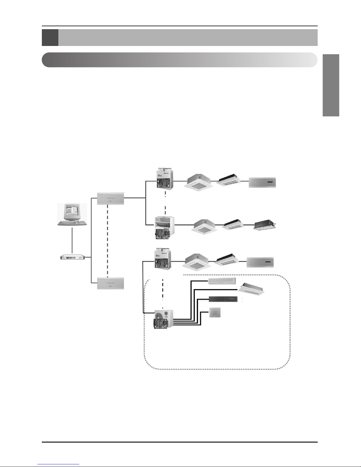
System Configuration
- 16 CNU / 1 PC Central Controller
-8PI485/1CNU
- 1Outdoor Unit / 1 PI485
•NOTE:If your requirement does not match above mentioned spec then Please Contact Airconditioner Department for support.
Multi V Outdoor Unit
1PC
Central Controller
PQNFP00A0
PMNFP14A0
PQNFP00A0
HUB
CNU(Interface)
LAN
MPS Outdoor
PMNFP14A0
70 71 7F
OF01
00
7C
7D
7F
F
1
00 01
0F
7E
External Wiring Diagram
4 PC Central Controller
External Wiring Diagram
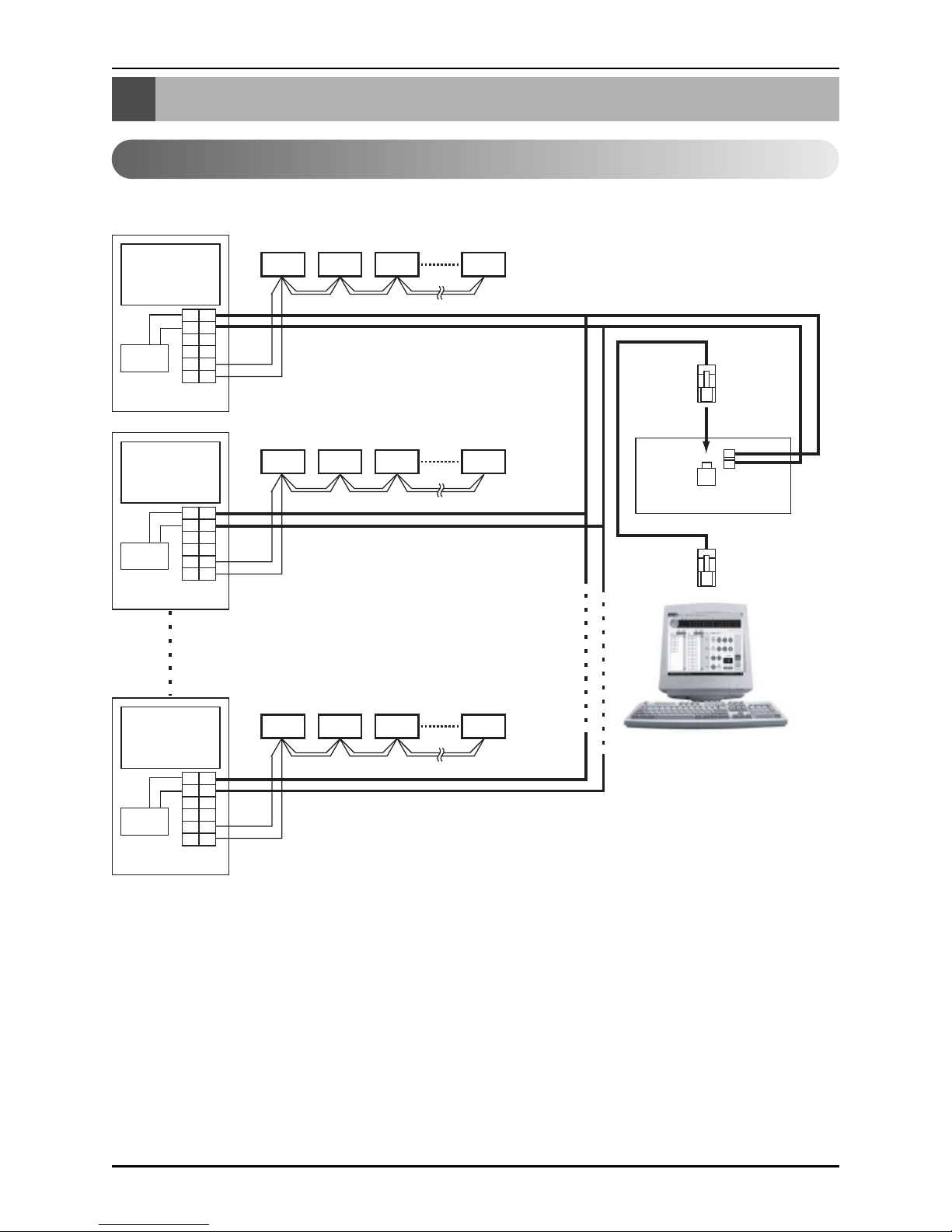
Multi V CRU(N)N
- Refer the wiring diagram and connect the communication line accordingly
A, B terminals are for connecting to Indoor units, and C, D terminals are for connecting to
CNU.
* Notice : Indoor unit address setting can be done by rotary switch in the Indoor unit PCB
Indoor units
00 01 02 0F
10 11 12 1F
F0 F1 F2 FF
LAN Port
CNU
(PQNFG00A0)
Cross
Cable
BUS A
BUS B
PI485
MAIN PCB
Outdoor unit 0
CC
AA
BB
D
VCC VCC
GND GND
D
PI485
MAIN PCB
Outdoor unit 1
CC
AA
BB
D
VCC VCC
GND GND
D
PI485
MAIN PCB
Outdoor unit 16
CC
AA
BB
D
VCC VCC
GND GND
D
PC Central Controller
External Wiring Diagram
Installation Manual 5
ENGLISH
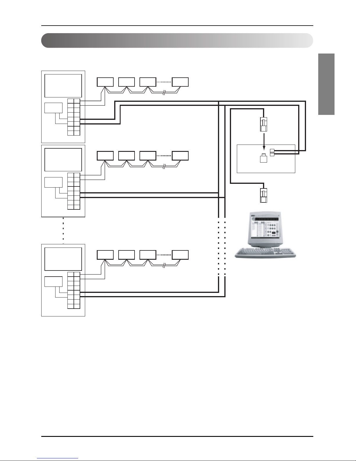
Multi-V PLUS & MPS Product
- Refer the wiring diagram and connect the communication line accordingly
A, B terminals are for connecting to Indoor units, and C, D terminals are for connecting to
CNU.
* Notice : Indoor unit address setting can be done by wired and wireless remote controller
Indoor units
00 01 02 0F
10 11 12 1F
F0 F1 F2 FF
LAN Port
CNU
(PQNFG00A0)
Cross
Cable
BUS A
BUS B
MAIN PCB
Outdoor unit 0
CC
AA
BB
D
VCC VCC
GND GND
D
EE
F
F
MAIN PCB
Outdoor unit 1
PI485
MAIN PCB
Outdoor unit 16
PI485
PI485
CC
AA
BB
D
VCC VCC
GND GND
D
EE
F
F
CC
AA
BB
D
VCC VCC
GND GND
D
EE
F
F
PC Central Controller

Internal Wiring Diagram
6 PC Central Controller
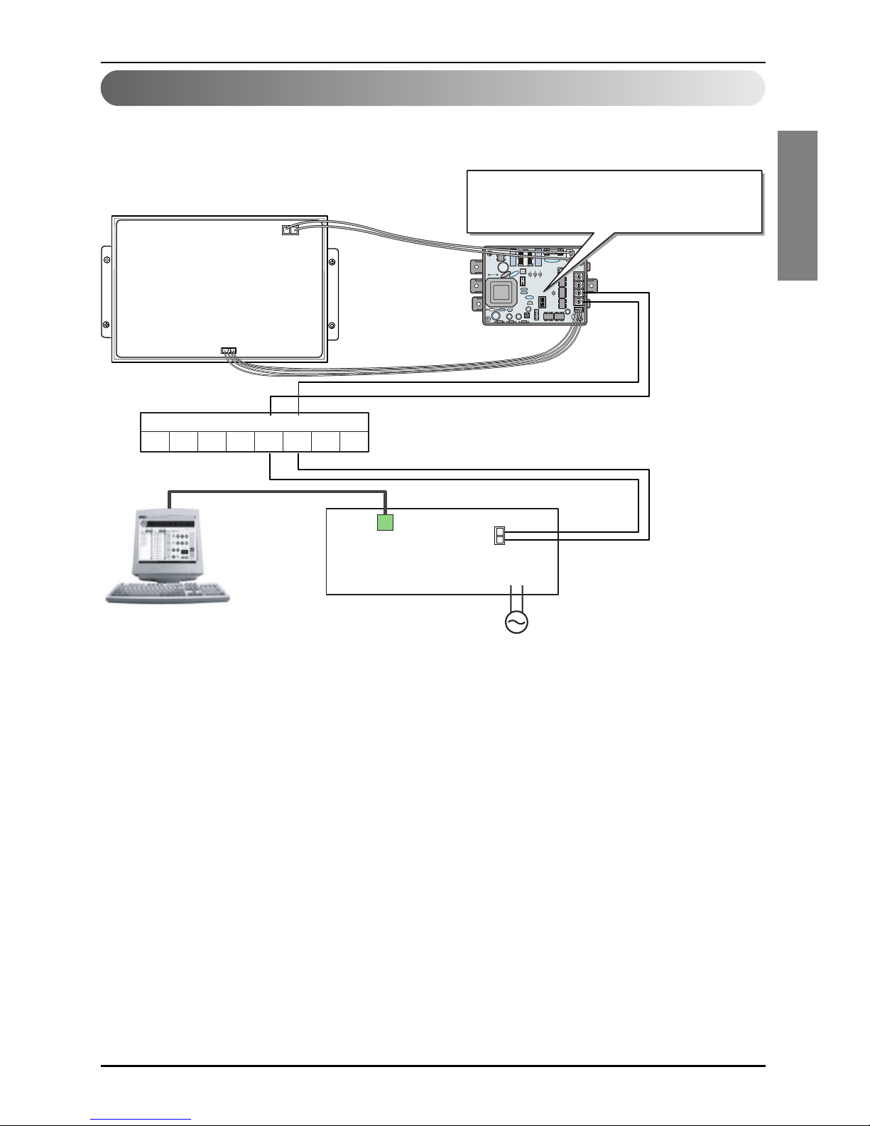
Internal Wiring Diagram
Multi V Terminal Block
ABCD
VCC GND
BUS_A
BUS_B
CNU
(PQNFG00A0)
Power terminal
AC 220~250 V 50/60Hz
LAN Port
PC Cental Controller
Multi V CRU(N)N
Outdoor Main PCB
CN_CENTRAL
Central Controller communication line
RS485 communication line
*Notice : CNU and PI485(PQNFP00A0, PQNFG00A0) should be purchased separately.
PI485
(PQNFP00A0)
Internal Wiring Diagram
Installation Manual 7
ENGLISH
Multi V PLUS & MPS Product
ON
L1 2 3 4
KSDO4H
BUS_A
BUS_A
BUS_B
BUS_B
Multi V Terminal Block
ABEFCD
VCC GND
CN_CENTRAL
Please refer to Network Interface setting method
on the next page.
It explains about how to set PI485(M) DIP switch.
Outdoor Main PCB
CNU
(PQNFG00A0)
Power terminal
AC 220~250 V 50/60Hz
PMNFP14A0
LAN Port
RS485 communication line
PC Central Controller
Note : Terminal Block Use in case of Multi V and other models may Or may not be present.
If it is not present, make direct connections.
Network Interface Connection
8 PC Central Controller
Network Interface Connection
ON
L1 2 3 4
KSDO4H
ON KSDO 4H
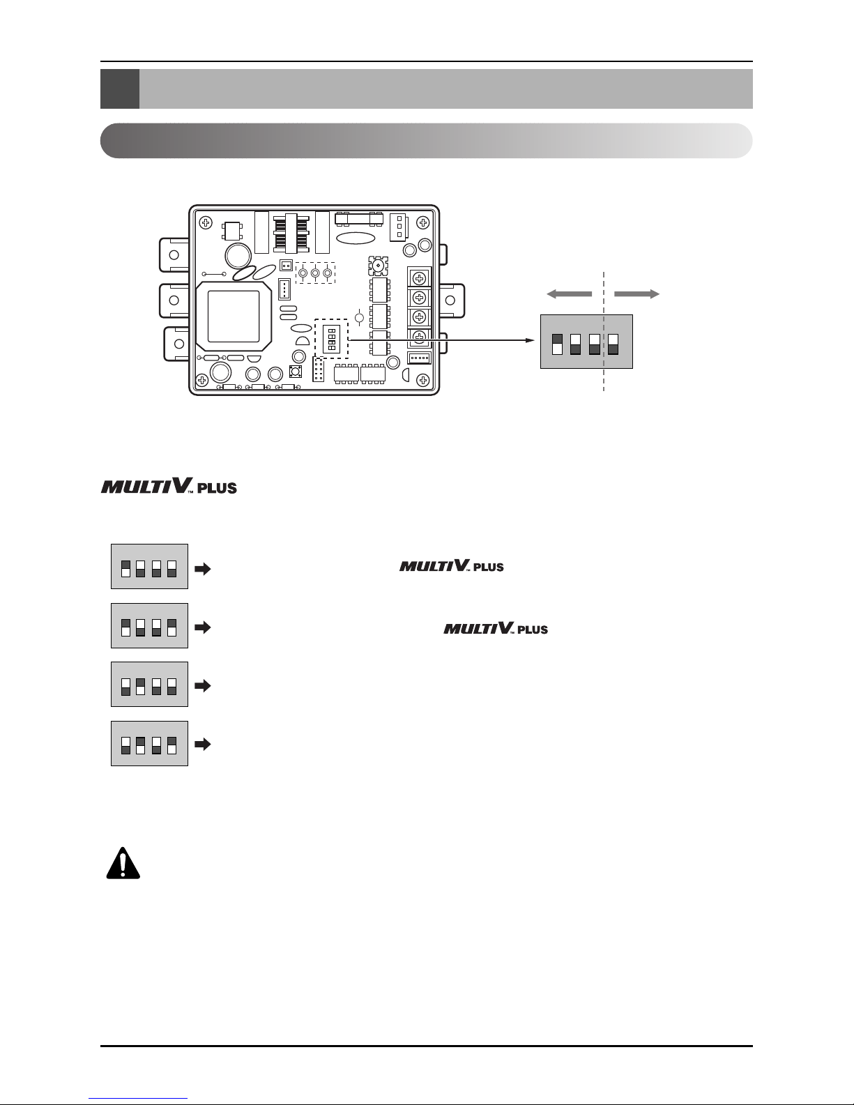
P1485(M) Dip Switch Configuration
ON KSDO4H
ON KSDO4H
ON KSDO4H
ON KSDO4H
Select Air
Conditioner Type
Select Network
Type
* LGAP : LG Air conditioner Protocol
1 ON, All others OFF: & MPS
Inverter Product + Central Controller (All types) Without LGAP
1and4ON,AllothersOFF: &MPS
Inverter Product + Central Controller (All types) Using LGAP
2 ON, All others OFF: MPS Multi Standard Product + Central Controller
(All types) - Without LGAP
2 and 4 ON, All others OFF: Multi Standard Product + Central Controller
(All types) - Using LGAP
& MPS MULTI Products Configuration Methods
CAUTION:
The wrong setting of air-conditioner switch could cause malfunctioning.
Switch setting must be done carefully.
* Please refer the corresponding Central Controller installation manual if you want to know whether
your Central Controller is compatible with LGAP or not.
Network Interface Connection
Installation Manual 9
ENGLISH
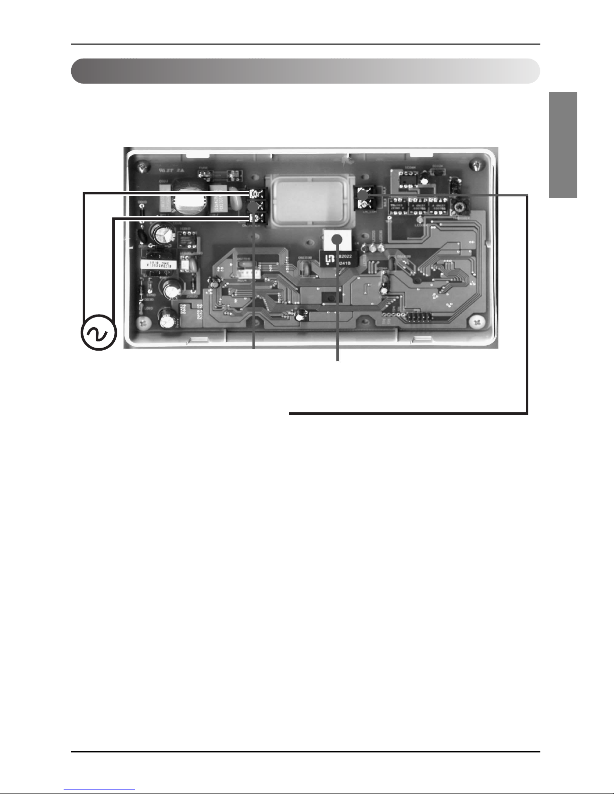
CNU Connection
CNU : Central Network Unit (PNFG00A0)
RJ45 Connector : Connect with HUB OR
Deluxe Central Controller
Power Terminal
AC 220~250 V 50/60Hz
RS-485 Communication Terminal
Connect with PNFP00A0 'C,D'
OR
Connect with PMNFP14A0 'A,B'
• NOTICE
PNFG00A0 ---- PNFP00A0 (PMNFP14A0)
BUS_A ---- BUS_C (BUS_A)
BUS_B ---- BUS_D (BUS_B)
Use two shield lines for RS-485 connecting line.
(Earth the shield line)
 Loading...