

Page 1

P/NO : MFL62049603
www.lg.com
INSTALLATION MANUAL
AIR CONDITIONER
• Please read this installation manual completely before installing the product.
• Installation work must be performed in accordance with the national wiring
standards by authorized personnel only.
• Please retain this installation manual for future reference after reading it
thoroughly.
TYPE : AHU EXPANSION KIT
Models : PATX13A0E PATX20A0E PATX25A0E
PATX35A0E PATX50A0E
ENGLISH
Page 2

2 AHU EXPANSION KIT
AHU EXPANSION KIT Installation Manual
TABLE OF CONTENTS
n Safety Precautions.............................................................3
n Installation Scene...............................................................5
n Supplies..............................................................................6
n EXPANSION KIT Installation .............................................7
n Mechanical installation ...............................................................................7
n Brazing work .............................................................................................10
n Pipe cutting work ......................................................................................11
n Thermistor connection..............................................................................12
n Leakage and vacuum test ...............................................15
n Leakage test.............................................................................................15
n Vacuum test..............................................................................................15
n
Superheat Adjustment ...............................................................
16
n
EXPANSION KIT installation confirmation plate preparation ...
17
Page 3
Safety Precautions
Installation Manual 3
ENGLISH
n Installation
Safety Precautions
To prevent injury to the user or other people and property damage, the following instructions must be followed.
n Incorrect operation due to ignoring instruction will cause harm or damage. The seriousness is
classified by the following indications.
n Meanings of symbols used in this manual are as shown below.
WARNING
CAUTION
This symbol indicates the possibility of death or serious injury.
This symbol indicates the possibility of injury or damage.
Be sure not to do.
Be sure to follow the instruction.
WARNING
Do not use the existing manifold gauge for
R22 refrigerant.
• To charge the refrigerant stably, always
use the manifold gauge for high pressure
(R410A).
Install the air conditioner at a designated
location using the designated material.
• Heat exchanger inlet/outlet pipe location.
Do not store or use
flammable gas or volatile
substance near the air
conditioner.
• It can cause a fire or problem
to the product.
Do not mix existing R22 pipe
and installation products for
the installation.
• When you mix the mineral oil
of R22 and R410A oil (PVE), it
can decompose with water to
cause problems to the product.
Do not mix other refrigerant
with the designated
refrigerant (R410A) during
the installation or moving
the air conditioner.
• When other refrigerant is
mixed with the original
refrigerant, it can cause a
problem in the refrigerant cycle
and damage the product.
System air conditioner can
only be installed by
specialized service provider
with air condition
installation certifications.
• Inappropriate installation can
cause leakage, fire and
electric shock.
When moving or reinstalling
the air conditioner, please
contact the
MULTI VTM AHU
installation service provider.
• Inappropriate installation can
cause leakage, fire and
electric shock.
Do not disassemble, repair
or reconfigure the product
arbitrarily.
• It can cause a fire and electric
shock.
Page 4
Safety Precautions
4 AHU EXPANSION KIT
n Operation
n Installation
Do not install the air conditioner outdoors.
• If installed outdoor inevitably, consult Multi
VTM
AHU installation service provider.
Do not let any worker or user climb on top of
the product.
• The person can get seriously injured.
Make sure that water does
not get inside the product
(Controller). Especially, do
not clean the product with
water.
• It can cause electric shock and
problems.
When the air conditioner is
submersed in water, always
consult
MULTI VTM AHU
installation service provider.
• It can cause a fire and electric
shock.
Do not keep any heating
devices near the product.
• It can cause a fire.
After the product installation
and repair, always check for
gas leakage.
• It can cause problems in the
product.
When installing the product,
always make sure to level to
the product.
• It can cause vibration and
leakage.
Do not install the product
where flammable gas leaks.
• It can cause a fire and
problems to the product.
n Operation
If the refrigerant leaked while installing the product, always ventilate the room.
• The refrigerant gas can react with the fire to turn into hazardous gas to cause an accident.
CAUTION
Page 5
Installation Manual 5
ENGLISH
Installation Scene
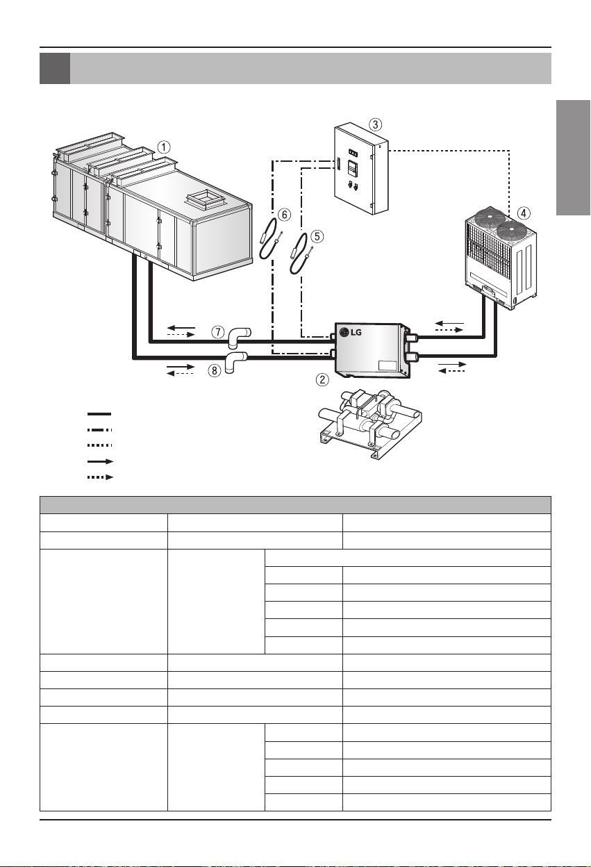
Installation Scene
Liquid pipe
Gas pipe
Refrigerant pipe
Thermistor
Communication line
Refrigerant flow (Cooling)
Refrigerant flow (Heating)
This EXPANSION KIT is the product connecting AHU and Outdoor unit configured as follows.
Installation components
No. Name Remarks
①
Air Handling Unit
-
②
EXPANSION KIT
Connectable outdoor unit capacity
PATX13A0E 8 ~ 16 HP
PATX20A0E 18 ~ 26 HP
PATX25A0E 28 ~ 36 HP
PATX35A0E 38 ~ 46 HP
PATX50A0E 48 ~ 56 HP
③
AHU control box -
④
Outdoor unit
Multi-VTM
⑤
Thermistor IN Sensor: Ø5, Length: 10m, Line color: Black
⑥
Thermistor OUT Sensor: Ø7, Length: 10m, Line color: Red
⑦
⑧
90° Elbow
PATX13A0E
⑦: Ø15.88 ⑧: Ø22.22
PATX20A0E
⑦: Ø22.2 ⑧: Ø28.58
PATX25A0E
⑦: Ø28.58 ⑧: Ø34.92
PATX35A0E
⑦: Ø34.92 ⑧: Ø41.3
PATX50A0E
⑦: Ø34.92 ⑧: Ø41.3
Page 6
6 AHU EXPANSION KIT
Supplies
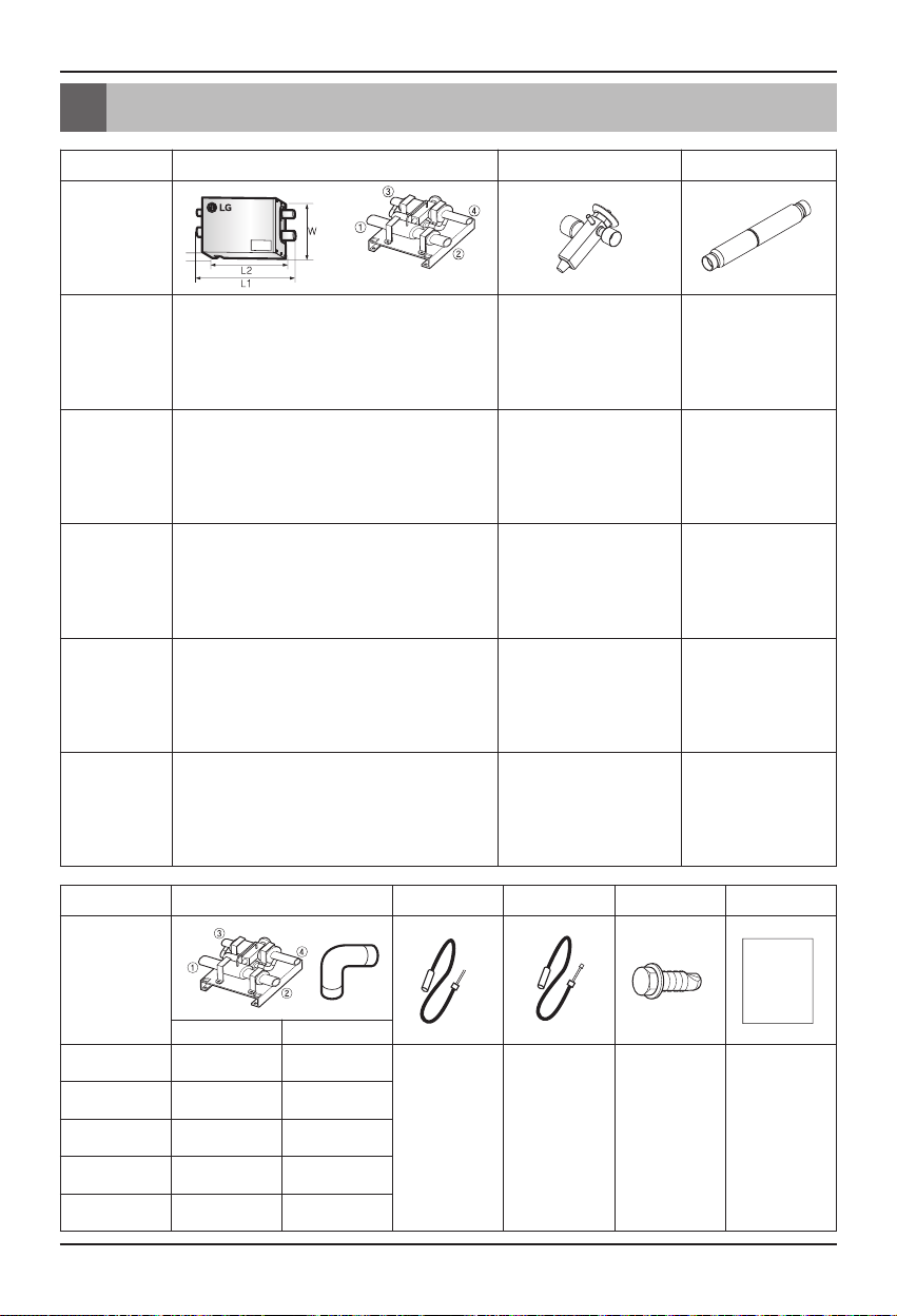
Supplies
q
EXPANSION KIT
TXV V/V CHECK V/V
Model naame
PATX13A0E
- Pipe diameter (mm) ①②:22.2
③ : 15.88
④ : 15.88
- L1 x L2 x W x H(mm) : 491 x 331 x 238 x 174
- Weight (NET/GROSS, kg): 5.6/6.9
- Norminal capacity : 20RT
- Applied Outdoor unit
capacity : 18~26HP
- Flow rate : 37l /min
PATX20A0E
- Pipe diameter (mm) ①②:28.58
③ : 22.2
④ : 15.88
- L1 x L2 x W x H(mm) : 491 x 331 x 238 x 174
- Weight (NET/GROSS, kg): 5.8/7.1
- Norminal capacity : 20RT
- Applied Outdoor unit
capacity : 18~26HP
- Flow rate : 37l /min
PATX25A0E
- Pipe diameter (mm) ①②:34.92
③ : 28.58
④ : 22.22
- L1 x L2 x W x H(mm) : 491 x 331 x 238 x 174
- Weight (NET/GROSS, kg): 6.0/7.3
- Norminal capacity : 25RT
- Applied Outdoor unit
capacity : 28~36HP
- Flow rate : 59l /min
PATX35A0E
- Pipe diameter (mm) ①②:41.3
③ : 34.92
④ : 28.58
- L1 x L2 x W x H(mm) : 491 x 331 x 238 x 174
- Weight (NET/GROSS, kg): 6.2/7.5
- Norminal capacity : 35RT
- Applied Outdoor unit
capacity : 38~46HP
- Flow rate : 59l /min
PATX50A0E
- Pipe diameter (mm) ①②:41.3
③ : 34.92
④ : 28.58
- L1 x L2 x W x H(mm) : 561 x 331 x 291 x 192
- Weight (NET/GROSS, kg): 8.5/10
- Norminal capacity : 50RT
- Applied Outdoor unit
capacity : 48~56HP
- Flow rate : 85l /min
90° Elbow
Thermistor IN
Thermistor OUT
Installation screw
Installation manual
Model name
Installation
manual
①(mm) ③(mm)
PATX13A0E 22.2 15.88
- Quantity: 1 unit
- Sensor: Ø5
Length: 10m
- Line color: Black
- Quantity: 1 unit
- Sensor: Ø7
Length: 10m
- Line color: Red
- Quantity:
4 screws
- Self drilling
screw (Direct
screw)
- 20mm
- Quantity:
1 unit
PATX20A0E 28.58 22.2
PATX25A0E 34.92 28.58
PATX35A0E 41.3 34.92
PATX50A0E 41.3 34.92
Page 7

Installation Manual 7
ENGLISH
EXPANSION KIT Installation
Mechanical installation
1. Unscrew the 4 screws on the side cover of
EXPANSION KIT.
2. Disassemble the side cover.
3. Unscrew the 2 screws on the top cover.
4. Disassemble the top cover.
5. Check the location and direction to install
EXPANSION KIT on the AHU.
EXPANSION KIT Installation
Page 8

8 AHU EXPANSION KIT
EXPANSION KIT Installation
-
You have to install EXPANSION KIT according to the installation location and direction provided in
the upper table according to the heat exchanger pipe and checking door direction of AHU.
Installation location of EXPANSION KIT
Installation direction of EXPANSION KIT
Left side Left side Left side Horizontal installation
Left side Right side Left side Horizontal installation
Right side Left side Right side Horizontal installation
Right side Right side Right side Vertical installation
AHU
EXPANSION KIT
Heat exchanger
pipe direction
Checking door
direction
Installation
location
Installation
direction
n You must install the Expansion Kit exactly as
shown in the above diagram. Otherwise, it will
cause failure. (Do not install with the header
directing downward.)
CAUTION
Right side
Left side
Gas pipe
Header
Liquid pipe
Gas pipe
Liquid pipe
<Horizontal installation> <Vertical installation>
Outdoor unit side
Liquid pipe Gas pipe
Liquid pipe Liquid pipe
AHU side
Gas pipe
Refrigerant flowing direction based on cooling
Outdoor unit side
Gas pipe
Liquid pipe
Gas pipe
AHU side
Page 9

Installation Manual 9
ENGLISH
EXPANSION KIT Installation
6. Use the installation component 90° elbow to
connect AHU and EXPANSION KIT.
7. Use the installation screw to tighten 4 locations of
the AHU casing and EXPANSION KIT.
8. Weld 4 connecting locations of AHU heat
exchanger pipe and 90° elbow and EXPANSION
KIT pipe.
9. Weld the connecting pipe (Field supply)
connected to the side of the outdoor unit.
10. When connecting the pipe on Outdoor unit and
EXPANSION KIT, always use the socket (Field
supply) that fits the specification.
11. As the size of the pipe connected to
Outdoor unit and EXPANSION
KIT can differ, always use the
socket Field supply that fits the
specification.
12. During all welding, always follow the
precautions. Always have the nitrogen gas flow
through as shown in the following figure during
all welding processes.
[Connection to outdoor unit]
[Connection to AHU]
Pipe connecting
to outdoor unit
(Field supply)
Connecting socket
(Field supply)
Page 10

10 AHU EXPANSION KIT
EXPANSION KIT Installation
n Be sure to carry out a nitrogen blow when brazing.
Brazing without carrying out nitrogen replacement or releasing nitrogen into the piping will
create large quantities of oxidized film on the inside of the pipes, adversely affecting
valves and compressors in the refrigerating system and preventing normal operation.
n When brazing while inserting nitrogen into the piping, nitrogen must be set to 0.02 MPa
with a pressure-reducing valve(just enough so that it can be felt on the skin).
CAUTION
n The leakage test is executed by pressurizing nitrogen gas up to 3.8MPa(38.7kgf/cm2)
(The test must be done with the service valve of the outdoor unit closed and the gas must
be pressurized at the liquid pipe, gas pipe and high/low pressure common pipe of the
outdoor unit), and the pressure of the nitrogen gas must not drop for 24 hours.
n For more details, refer to the manual of the outdoor unit.
a Refrigerant piping b Part to be brazed
c Taping d Hands valve
e Pressure-reducing valve f Nitrogen
Brazing work
a b
c
e
d
brazing
f
f
Page 11

Installation Manual 11
ENGLISH
1. Always use the copper pipe cutter when cutting the pipe.
2. Always remove the burr.
(Keep the end of the pipe facing down during the work and make sure that the burr does
not get inside the pipe.)
EXPANSION KIT Installation
n Always cut in a straight
line for the cut part.
CAUTION
n If the burr gets inside, it can cause leakage of refrigerant. Therefore always
remove the burr with a reamer.
n Cut pieces can cause problems when they go inside the pipe.
CAUTION
n Always make sure that the refrigerant is not leaking during the welding.
n When the refrigerant is burnt, it generates a toxic gas hazardous to the human
body.
n Do not proceed the welding work in a closed location.
n After the pipe welding, always do a leakage test.
WARNING
n When welding the part, always pass it through nitrogen. If not, the compressor
may not work or can be damaged.
n Before/After the welding, wrap the area with a wet water cloth. If not, the part
can be damaged.
n Use a protective panel or pay special attention so that the welding torch flame
does not directly touch AHU casing.
n After the welding, always do a leakage test.
CAUTION
Pipe cutting work
Copper
pipe cutter
Pipe
Pipe
Reamer
Pipe
Cut pieces
Tilted Rough
Reamer
Page 12

12 AHU EXPANSION KIT
EXPANSION KIT Installation
Thermistor connection
1. Insert the Thermistor IN/OUT to the correct
location on the sensor holder.
2. Set the same inserting location of the
Thermistor as shown in the picture.
3. Insert the Thermistor so that it is inserted to
the end of the sensor holder.
4. After the Thermistor is inserted, insulate the
welded part with insulation material (15T or
above).
5. Assemble the Top cover of EXPANSION KIT
and tighten 2 screws.
6. Use the flexible pipe and connector for the 2
types of connected Thermistor to pull them
out of EXPANSION KIT.
7. Always pull the Thermistor using the
flexible pipe and use specified product
(Ø16) for the flexible pipe and connector.
8. Assemble the side cover of EXPANSION KIT
and screw the 4 screws.
9. Fixate the flexible pipe inserted with the
Thermistor to the AHU external casing, and
connect it all the way to the AHU control box.
Thermistor
IN
Thermistor
OUT
Insulate 4 location of the connecting part
Flexible pipe and connector:
Ø16 (Field supply)
Thermistor IN
Thermistor OUT
Sensor
holder
Page 13

Installation Manual 13
ENGLISH
EXPANSION KIT Installation
[COMMUNICATION PCB CONFIGURATION]
10. Distinguish and connect the IN and OUT on the Thermistor terminal on the
communication PCB inside AHU CONTROL KIT.
11. Check the rotary switch number and write the installation confirmation plate of
EXPANSION KIT.
The error number displayed on AHU Controller in case of an error is displayed
for the rotary switch number, and error on Outdoor unit can be easily
estimated during the service.
n 2 EXPANSION KIT and Outdoor unit are connected to one communication PCB,
and each is classified and connected.
Ex) EXPANSION KIT A, Outdoor unit A, outdoor communication line A, thermistor
A IN, thermistor A OUT
‘ All connected to A circuit
EXPANSION KIT B, Outdoor unit B, outdoor communication line B, thermistor
B IN, thermistor B OUT
‘ All connected to B circuit
CAUTION
Thermistor #B OUT
Rotary switch #B
Thermistor #B IN
Outdoor unit communication line #B
Thermistor #A OUT
Outdoor unit communication line #A
Thermistor #A IN
Rotary switch #A
confirmation plate
Installation
Page 14

14 AHU EXPANSION KIT
EXPANSION KIT Installation
[INSTALLATION CONFIGURATION EXAMPLE]
Thermistor
[AHU control box]
Thermistor
A (Outdoor unit 1)
Liquid pipe
Gas pipe
Refrigerant flow direction
based on cooling
B (Outdoor unit 2)
Liquid pipe
Gas pipe
Refrigerant flow direction
based on cooling
Communication PCBAHU Controller
Refrigerant pipe
AHU communication line
Thermistor
Page 15

Installation Manual 15
ENGLISH
Leakage and vacuum test
Leakage and vacuum test
Leakage test
Execute the leakage test in the same criteria as MULTIVTM leakage test.
Leakage test is done by apply nitrogen gas at 3.8MPa (38.7kgf/cm
3
). Refer to the following
picture for the test method. (Test with the service valve closed and pressurize the liquid and gas
pipe.)
After the nitrogen gas is pressurized, the pressure must not drop for 24 hours.
Ⓐ Nitrogen gas
Ⓑ Indoor unit direction
Ⓒ Manifold gauge
Ⓓ Low pressure side handle
Ⓔ High pressure side handle
Ⓕ Service valve
Ⓖ Gas pipe
Ⓗ Liquid pipe
Ⓘ Outdoor unit
Ⓙ Service port
Vacuum test
Ⓐ Manifold gauge
Ⓑ
Low pressure side handle
Ⓒ
High pressure side handle
Ⓓ Service valve
Ⓔ Liquid pipe
Ⓕ Gas pipe
Ⓖ Service port
Ⓗ 3 way joint
Ⓘ Valve
Ⓙ Valve
Ⓚ R410A cylinder
Ⓛ
Weight: Use a
gravitational weight
(Use one that can
measure up to 0.1kg)
If you cannot get a
high precision
weight, you can also
use the charging
cylinder.
Ⓜ Vacuum pump
Execute the vacuum test in the same criteria as MULTIVTM vacuum test.
As shown in the below picture, close the service valve of the outdoor unit with the vacuum pump and execute the
vacuuming process on the connecting pipe and AHU from the service port of the stop valve. (Liquid and gas pipe
must always be vacuumed from the service port.)
When the vacuum level reaches 5 Torr, additionally vacuum for 1 hour, and the vacuum level must not change for 1 hour.
(If there is any change, there should be moisture or leakage within the pipe.)
If there is a possibility of moisture within the pipe, vacuum for 2 hours and insert the nitrogen gas at 0.05Mpa
(0.5kgf/cm
3
).
After this vacuum for another 1 hour to reach 5 Torr. Maintain the vacuum for 1 hour and check for changes in vacuum gauge.
* Never purge the air with the refrigerant.
* Always execute the vacuuming with the vacuum pump with vacuum gauge attached.
Low
pressure
High
pressure
Low
pressure
High
pressure
Page 16

16 AHU EXPANSION KIT
Leakage and vacuum test
- Add the accurate amount of refrigerant after the calculation.
- If the amount of refrigerant is not accurate, it can cause problems to the product.
- If the additionally inserted amount of refrigerant exceeds ±10%, the compressor can be
burnt and the indoor unit can underperform.
n Pipe to vacuum: Gas pipe and liquid pipe
n When moving the product to a different location, do not charge a different
refrigerant than the regulated refrigerant (R410A).
n If other refrigerant is mixed to the original refrigerant, it can cause a malfunction in
the refrigerant cycle to cause damages.
n As the refrigerant composition of R410A changes when inserted in gas condition,
always insert the refrigerant in liquid condition.
CAUTION
1. After removing the cap nut, turn the stem clockwise to increases superheat / decreases
refrigerant flow.
2. Superheat change per 1 turn of adjustment stem according to the evaporator temperature.
* Factory setting on preset valves is 9°F / 5°C static superheat.
* Even if the superheat adjustment, system operates according to the logic to meet the target low
pressure.
Superheat Adjustment
Evaporator Temperature +32°F / 0° C +41°F / +5° C
Superheat change / turn 2.52°F / 1.4°C 2.16°F / 1.2°C
<View of Adjustment Stema>
Counter-Clockwise
increase SH
Clockwise
decrease SH
stem
cap nut
Page 17

Installation Manual 17
ENGLISH
EXPANSION KIT installation confirmation plate preparation
EXPANSION KIT installation confirmation plate preparation
When the installation of EXPANSION KIT is completed, prepare the installation confirmation plate.
Site name
EXPANSION
KIT
Outdoor
unit
Communication PCB rotary S/W No.
Connecting
pipe size (mm)
EXPANSION
KIT
Outdoor
unit
Communication PCB rotary S/W No.
Connecting
pipe size (mm)
EXPANSION
KIT
Outdoor
unit
Communication PCB rotary S/W No.
Connecting
pipe size (mm)
Model name
Outdoor unit capacity
No.
Model name
Installation location
AHU side
Outdoor unit side
Site name
Model name
Outdoor unit capacity
No.
Model name
Installation location
AHU side
Outdoor unit side
Site name
Model name
Outdoor unit capacity
No.
Model name
Installation location
AHU side
Outdoor unit side
Site name
EXPANSION
KIT
Outdoor
unit
Communication PCB rotary S/W No.
Connecting
pipe size (mm)
Gas pipe:
Gas pipe:
Gas pipe:
Gas pipe:
Gas pipe:
Gas pipe:
Model name
Outdoor unit capacity
No.
Model name
Installation location
AHU side
Outdoor unit side
PATX13A0E
8 ~ 16 HP
22.22 /
Liquid pipe:
22.22 /
Liquid pipe:
PATX25A0E
28 ~ 36 HP
34.92 /
Liquid pipe:
34.92 /
Liquid pipe:
PATX50A0E
48 ~ 56HP
41.3/
Liquid pipe:
41.3 /
Liquid pipe:
15.88
15.88
28.58
22.22
34.92
28.58
PATX13A0E
8 ~ 16 HP
Gas pipe:
22.22 /
Liquid pipe:
Gas pipe:
22.22 /
Site name
EXPANSION
KIT
Outdoor unit capacity
Outdoor
unit
Communication PCB rotary S/W No.
Connecting
pipe size (mm)
Site name
EXPANSION
KIT
Outdoor unit capacity
Outdoor
unit
Communication PCB rotary S/W No.
Connecting
pipe size (mm)
15.88
Liquid pipe:
15.88
Model name
No.
Model name
Installation location
AHU side
Outdoor unit side
Model name
No.
Model name
Installation location
AHU side
Outdoor unit side
Gas pipe:
Gas pipe:
Gas pipe:
Gas pipe:
PATX20A0E
18 ~ 26 HP
28.58 /
Liquid pipe:
28.58 /
Liquid pipe:
PATX35A0E
38 ~ 46HP
41.3/
Liquid pipe:
41.3 /
Liquid pipe:
22.22
15.88
34.92
28.58
Page 18

18 AHU EXPANSION KIT
Page 19

 Loading...