

LG PAHCNM000 Owner’s Manual
OWNER’S &
INSTALLATION MANUAL
AIR
CONDITIONER
Please read this installation manual completely before installing the product.
Installation work must be performed in accordance with the national wiring standards by
authorized personnel only.
Please retain this installation manual for future reference after reading it thoroughly.
Applied(AHU)
AHU CONTROL KIT
Original instruction
[Representative] LG Electronics Inc. EU Representative : LG Electronics
European Shared Service Center B.V. Krijgsman 1, 1186 DM Amstelveen, The Netherlands
[Manufacturer] LG Electronics Inc. Changwon 2nd factory 84, Wanam-ro,
Seongsan-gu, Changwon-si, Gyeongsangnam-do, KOREA
www.lg.com
Copyright © 2019 - 2021 LG Electronics Inc. All Rights Reserved.
MFL71386003
Rev.04_040821
ENGLISH
ESPAÑOL FRANÇAIS DEUTSCH
PORTUGUÊS
SAFETY INSTRUCTIONS
2
ENGLISH
SAFETY INSTRUCTIONS
The following safety guidelines are intended to prevent unforeseen
risks or damage from unsafe or incorrect operation of the appliance.
The guidelines are separated into ‘WARNING’ and ‘CAUTION’ as
described below.
This symbol is displayed to indicate matters and operations
!
that can cause risk.
Read the part with this symbol carefully and follow the
instructions in order to avoid risk.
WARNING
!
This indicates that the failure to follow the instructions can
cause serious injury or death.
CAUTION
!
This indicates that the failure to follow the instructions can
cause the minor injury or damage to the product.
WARNING
!
• Installation or repairs made by unqualified persons can result in
hazards to you and others.
• The information contained in the manual is intended for use by a
qualified service technician familiar with safety procedures and
equipped with the proper tools and test instruments.
• Failure to carefully read and follow all instructions in this manual
can result in equipment malfunction, property damage, personal
injury and/or death.
Installation
• For installation of the product, always contact the service center
or a professional installation agency.
- Otherwise, it may cause fire, electrical shock, explosion or
injury.

SAFETY INSTRUCTIONS
3
• Securely attach the electrical part cover to AHU Communication
Kit.
- If the electric part cover of AHU Communication Kit is not
attached securely, it could result in a fire or electric shock due
to dust, water, etc.
• Do not keep or use flammable gases or combustibles near the
equipment.
- Otherwise, it may cause a fire or the failure of product.
• Do not install, remove or reinstall the unit by yourself.
- Otherwise, it may cause a fire, electrical shock, explosion or
injury.
• Do not disassemble or repair the product randomly.
- It will cause a fire or electrical shock.
• Do not install the product in a place where there is the concern of
falling down.
- Otherwise, it may result in personal injury.
• Use caution when unpacking and installing.
- Sharp edges may cause injury.
• Always ground the product.
- There is risk of fire or electric shock.
• Do not install the product on a non-parallel or defective
installation stand.
- It may cause injury, accident, or damage to the product.
ENGLISH
Operation
• Keep flames away.
- Otherwise, may occur a fire.
• Do not use the power cord near the heating tools.
- Otherwise, it may cause a fire and electrical shock.
• Do not allow water to run into electrical parts.
- Otherwise, it may cause the failure of machine or electrical
shock.
• Be cautious that water could not enter the product.
- Otherwise, it may cause a fire electrical shock or product
damage.

ENGLISH
SAFETY INSTRUCTIONS
4
• Do not place a heavy object on the power cord.
- Otherwise, it may cause a fire or electrical shock.
• When the product is submerged into water, always contact the
service center.
- Otherwise, it may cause a fire or electrical shock.
CAUTION
!
Installation
• Do not install the product direct sunlight.
• Do not insert a drain hose in drain or soil pipe.
- Bad smells can occur and it results in a corrosion of a heat
exchanger or pipe.
Operation
• If anyone other than a licensed Professional installs, repairs, or
alters LG Electronics Air Conditioning Products, the warranty is
voided.
- All costs associated with repair are then the full responsibility of
the owner.
• This appliance is not intended for use by persons (including
children) with reduced physical, sensory or mental capabilities, or
lack of experience and knowledge, unless they have been given
supervision or instruction concerning use of the appliance by a
person responsible for their safety.
- Children should be supervised to ensure that they do not play
with the appliance.
TABLE OF CONTENTS
2 SAFETY INSTRUCTIONS
6 INSTALLATION LAYOUT
6 Installation composition diagram
6 Caution on installation layout
7 PRODUCT DIMENSION
7 Product Measurements
8 PARTS LAYOUT
9 WIRING DIAGRAM
10 AHU CONTROL KIT INSTALLATION
10 Determining the product's mounting location
11 Things to keep in mind when installing outdoors
12 Sensor Cover Installation (outdoors)
13 AHU CONTROL KIT SETTINGS
13 Check Module Configuration
15 PIPE THERMISTOR CONNECTION
TABLE OF CONTENTS
5
ENGLISH
16 OUTDOOR UNIT COMMUNICATION LINE CONNECTION
16 Cautions on connecting the EEV module (communication module) with outdoor unit
16 Capacity Control Communication Cable Connection
17 INSTALLATION AND WIRING METHOD (OPTIONAL)
17 Installation method when adding EEV module
17 Wiring method when adding EEV module.
18 AHU SENSOR SPECIFICATION
20 AHU SENSOR CONNECTION
20 Sensor connection
25 Electrical Wiring (if using a belt driven fan)
26 Connect the electric wires
27 Things to keep in mind when installing the Control Kit on site
28 HMI SETTINGS
28 HMI Settings
45 Self-Diagnosis
INSTALLATION LAYOUT
6
ENGLISH
INSTALLATION LAYOUT
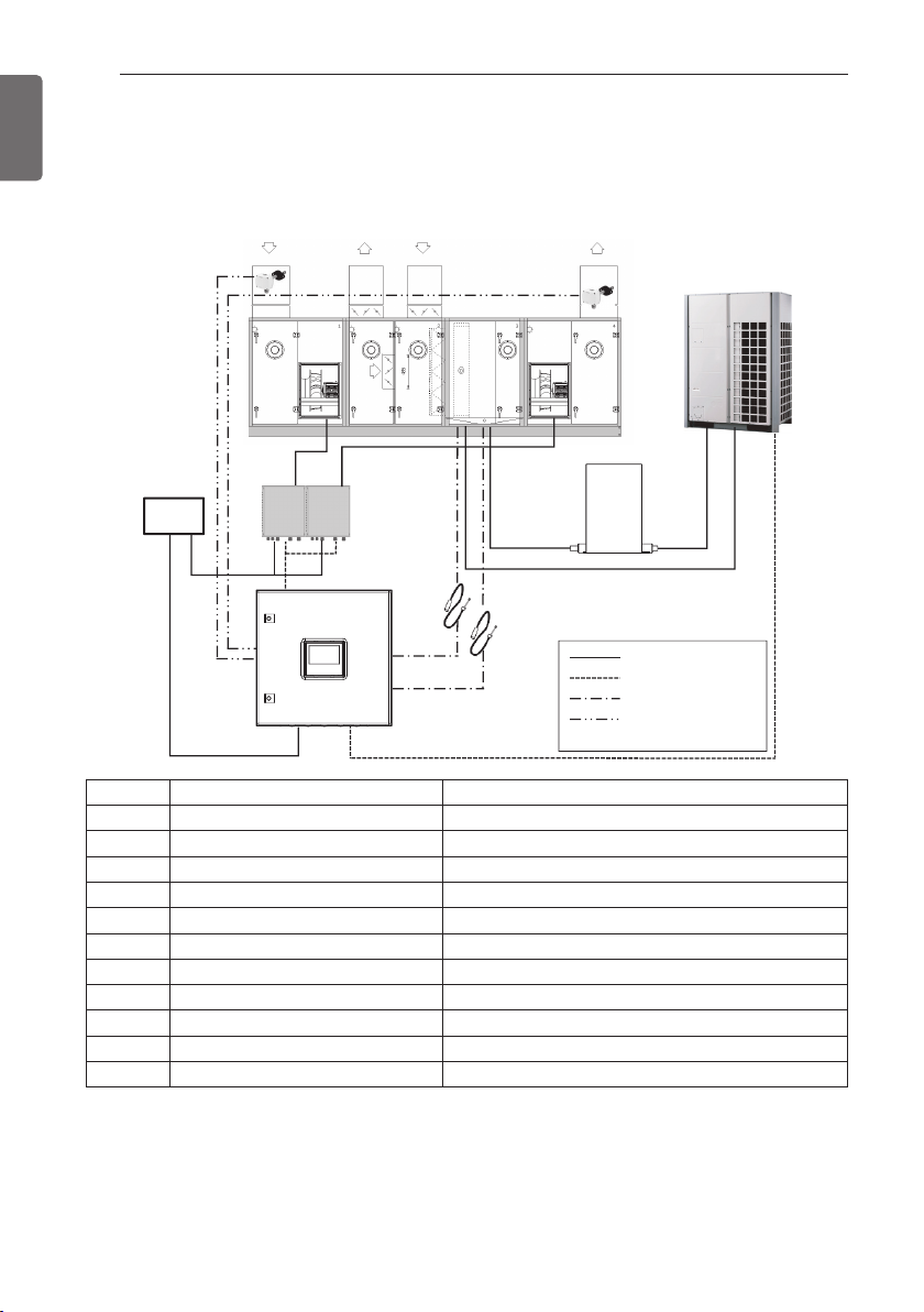
Installation composition diagram
RA
ῧ-1
Ῡ-1ῪῩ-2
MCC
ῢ
No. Item Applied Standards
①
②
③
④
⑤
⑥
⑦-1, 2
⑧-1, 2
⑨-1, 2
⑩
⑪
AHU CONTROL KIT PAHCNM000
Expansion kit -
Outdoor unit MULTI V
Pipe in Thermistor(Liquid)
Pipe out Thermistor(Gas)
Temperature/humidity sensor RA, SA Optional
Ventilation Fan, Supply Fan -
Inverter drive kit -
Main power switch board MCC switch board panel
EA OA SA
ῧ-2
Ῠ-1 Ῠ-2
ῥ
ῦ
Ύ
AHU -
Sensor : Ø 5(NTC 5 kΩ), Length : 5 m, Cable color : Black
Sensor : Ø 7(NTC 5 kΩ), Length : 5 m, Cable color : Red
HMI -
ῡ
Power cable
Communication cable
Thermistor signal
Temperature /
humidity sensor
ῤ
Caution on installation layout
- MCC is part of the installation construction to be performed by the equipment supplier, so
confer with the supplier before installing the product.
- Temperature/humidity sensors must be installed on the SA (supply)/RA(ventilation) ducts before
the product can run normally.
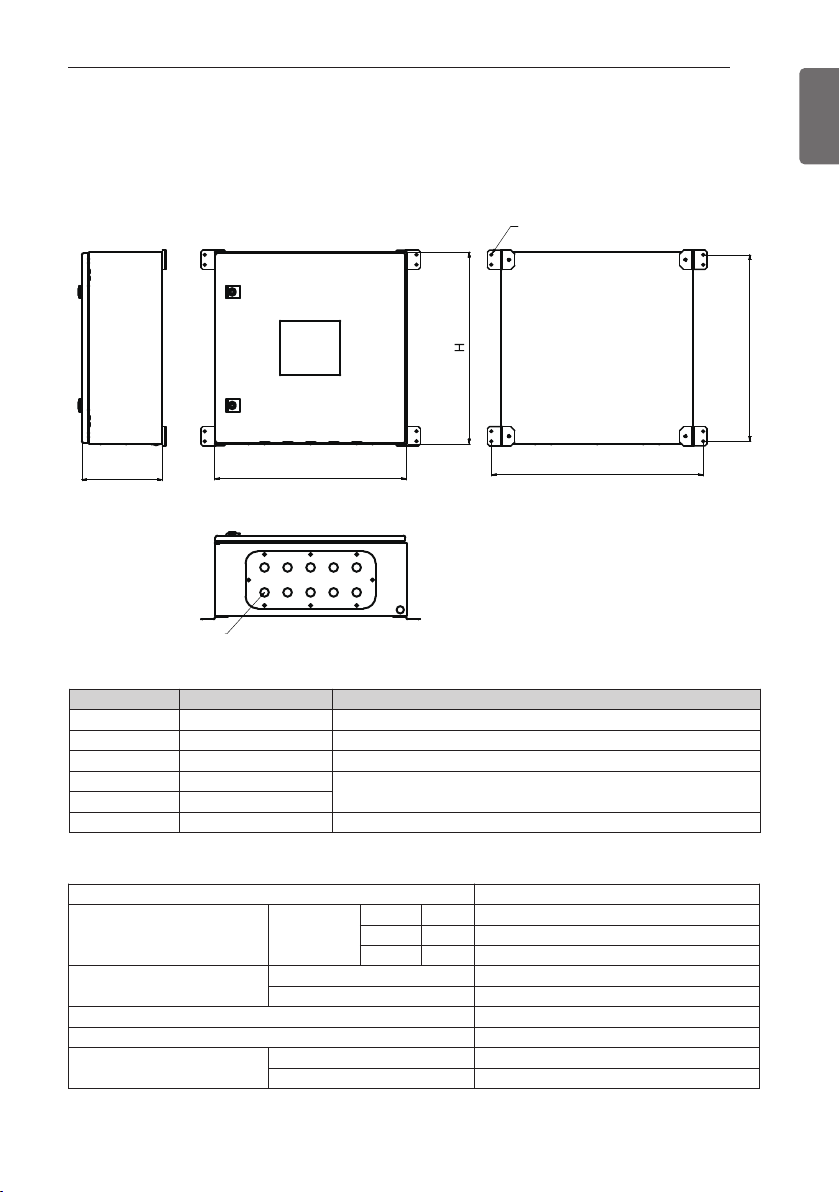
PRODUCT DIMENSION
Product Measurements
PRODUCT DIMENSION
8-Ø7 Holes
7
ENGLISH
B
DW
(Front)(Side) (Back)
C
(Bottom)
Classification Spec Description
W (mm) 500 Width
H (mm) 500 Height
D (mm) 210 Depth
A (mm) 552
B (mm) 486
C 22.5Ø Hole(10 EA) Power cable, Sensor/Communication line insert part
Use the appropriate flexible tubing and connectors for the corresponding holes.
Model PAHCNM000
Size Product
Enclosure
Power 220-240 V~, 50/60 Hz
Rated current 0.2 A
Product Operating
Environment Conditions
Operating Temperature -20 ~ 65 °C DB
Distance between wall mounting brackets
W mm 500
D mm 210
H mm 500
Color RAL 7035
Material Steel
Humidity 0 ~ 98 %
A
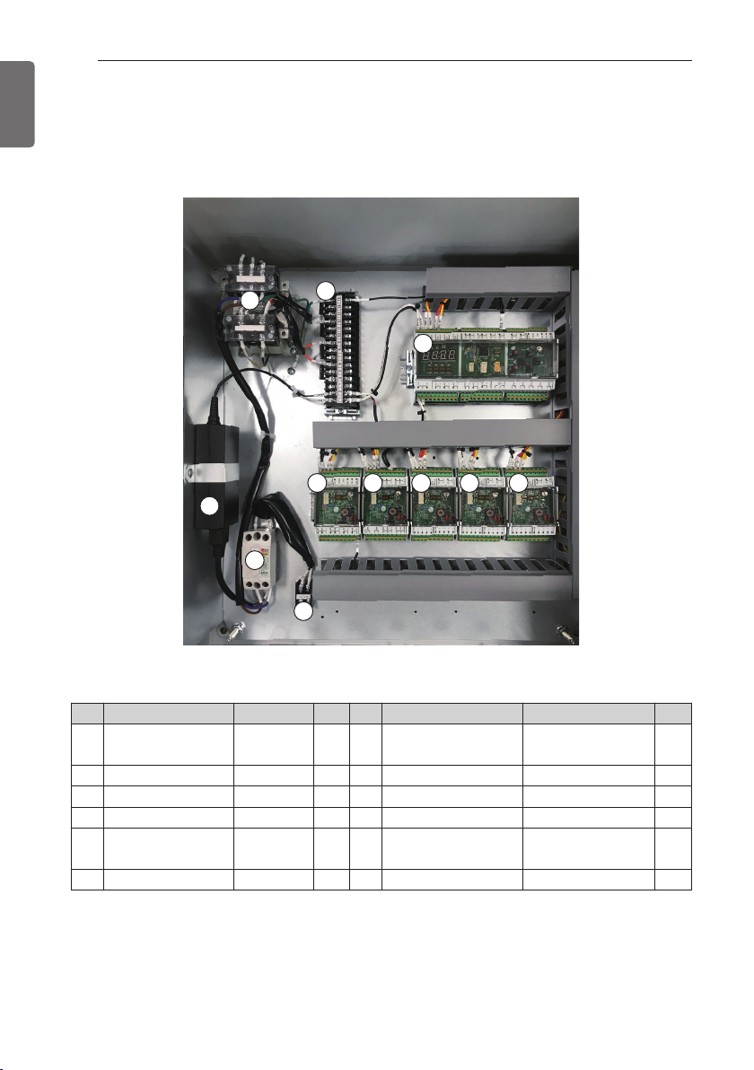
PARTS LAYOUT
10
1
8
7
11
2 3 4 5 6
9
8
ENGLISH
PARTS LAYOUT
• PAHCNM000
No. Main module Spec Qty. No. Main module Spec Qty.
①
②
③
④
⑤
⑥
Main module DC 12 V 1
UI module DC 12 V 1
UO module DC 12 V 1
EEV module #1 DC 12 V 1
EEV module #2 DC 12 V 1
EEV module #3 DC 12 V 1
NFB(No Fuse
⑦
⑧
⑨
⑩
⑪
Breaker)
Adaptor
Trans
Terminal Block 15 PIN 1
Terminal Block
15 A 1.5 kA 1
220 V → DC 12 V
220 V → AC 24 V
Single phase
220 V~, 60 Hz
1
1
1
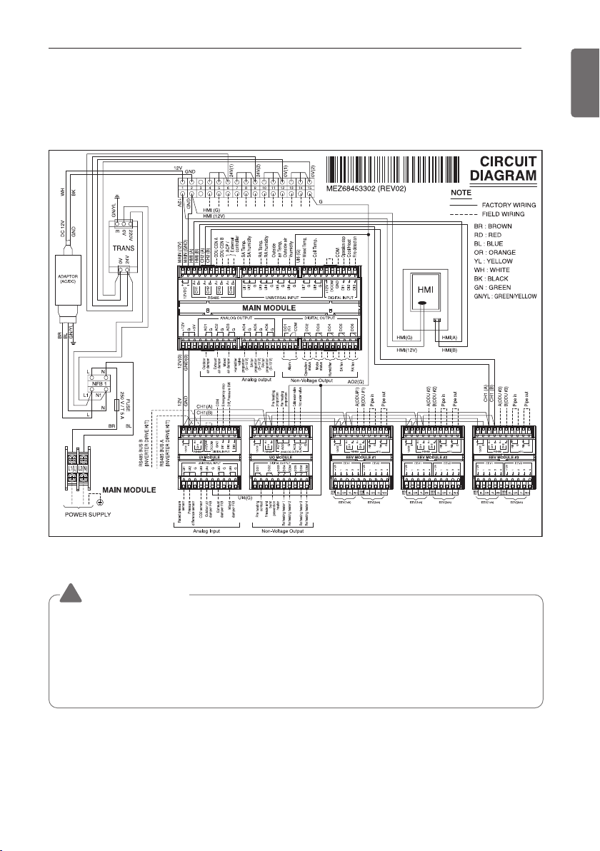
WIRING DIAGRAM
• PAHCNM000
WIRING DIAGRAM
9
ENGLISH
CAUTION
!
• In order to use the main module's shutdown, heating/cooling, and fire detection functions,
the main module's +12V terminal should be connected to the DCOM terminal. Failure to
do so could result in the malfunctioning of the product.
• In order to use the UI module's emergency shutdown and differential pressure switch
functions, the UI module's +12V terminal should be connected to the DCOM terminal.
Failure to do so could result in the malfunctioning of the product.
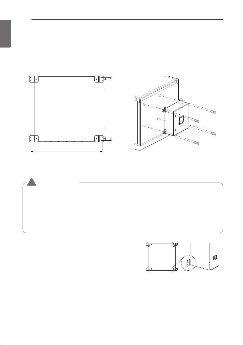
AHU CONTROL KIT INSTALLATION
10
ENGLISH
AHU CONTROL KIT INSTALLATION
Determining the product's mounting location
- The control kit's mounting location should be determined based on the conditions on site.
When mounting the control kit, use Ø 6 direct screws (8 EA).
2626
486
552
<Back Side of Control Kit>
CAUTION
!
• When installing the control kit, make sure to leave at least 900 mm between the wall and
the product case so there is enough room for servicing and installation.
• After mounting the product, check whether it is properly affixed.
• If the control kit has to be installed outdoors, be sure to also install an enclosure.
• When installing load devices such as AHU sensors and dampers outdoors, fitted covers
must also be mounted to protect them from the effects of the external environment.
- When using wall mount brackets, fasten the brackets to
the four holes on the rear of the enclosure.
- Please use the provided bolts, nuts, and washers to
fasten the brackets.
AHU CONTROL KIT INSTALLATION
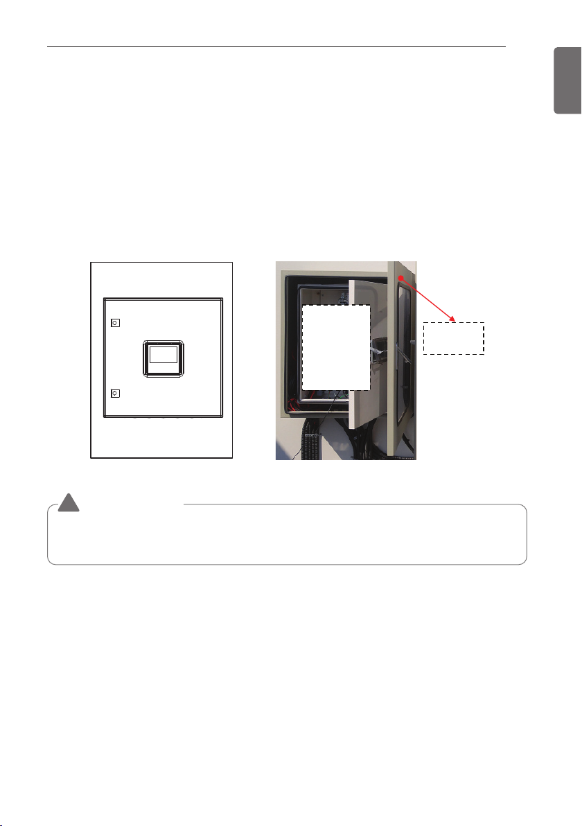
Things to keep in mind when installing outdoors
- Enclosures should be purchased separately if needed.
- After mounting the product, check the tightness of the connection between the AHU and the
enclosure.
If the connection is not airtight, moisture or dust could contaminate the product.
- When installing the AHU outdoors, be sure to use an enclosure to protect the control kit.
- The enclosure should be made of SUS or painted sheet metal to prevent corrosion.
- Make the structure so that it is easy to perform wiring tasks.
- The installation form and location may vary by site.
- Panels installed outdoors must be installed in a place that is not exposed to direct sunlight.
11
ENGLISH
AHU
Control
kit
CAUTION
!
Exposure to direct sunlight could raise the temperature inside the control kit and cause the
unit to malfunction.
Additional
enclosure
AHU CONTROL KIT INSTALLATION
12
ENGLISH
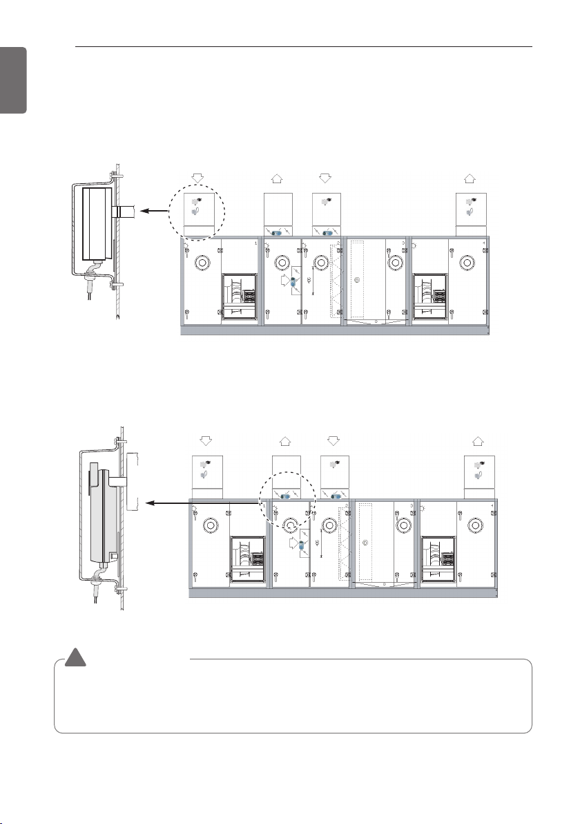
Sensor Cover Installation (outdoors)
When installing the AHU outdoors, make sure to install the protection box as shown below.
Ex: Installation of a temperature and temperature/humidity sensor covers.
RA EA OA
Ex: Installation of a damper actuator cover.
RA SA
EA OA
SA
CAUTION
!
• When installing a sensor outdoors, make sure to install the protective cover, at which time
the Safety Grade must be IP 56 or higher. If the cover is not installed, rainwater can flood
the sensor, causing it to malfunction.
AHU CONTROL KIT SETTINGS
AHU CONTROL KIT SETTINGS
Check Module Configuration
13
ENGLISH
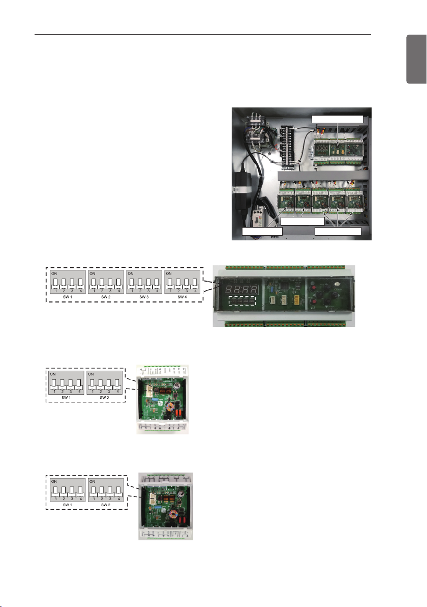
- After installing the Control Kit, the first thing
you should do is check the module settings
inside the Control Kit.
The DIP switches for the main module, UI
module, and UO module are configured in
the following order.
- The default setting of the DIP switches for
the main module, UI module, and UO
module is OFF. Do not change the settings
arbitrarily.
Main Module
UI Module
UI Module
(Main Module)
Main Module
UO Module
EEV Module
(UI Module)
UO Module
(UO Module)
The default setting for all DIP switches is OFF. (factory condition)
AHU CONTROL KIT SETTINGS
14
ENGLISH
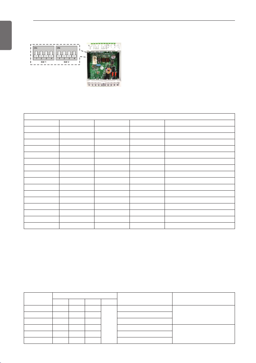
EEV Module
Capacity Settings
Use DIP switch SW1 to set the capacity.
1234Capacity [kW (kBtu/h)]
OFF OFF OFF OFF 2.1 (7)
OFF OFF OFF ON 2.5 (9)
OFF OFF ON OFF 3.5 (12)
OFF OFF ON ON 5.6 (18)
OFF ON OFF OFF 7.1 (24)
OFF ON OFF ON 8.2 (28)
OFF ON ON OFF 10.6 (36)
OFF ON ON ON 12.3 (42)
ON OFF OFF OFF 14.1 (48)
ON OFF OFF ON 22.4 (76)
ON OFF ON OFF 28.0 (96)
ON OFF ON ON 33.6 (115)
ON ON OFF OFF 39.2 (134)
ON ON OFF ON 44.8 (153)
ON ON ON OFF 50.5 (172)
ON ON ON ON 56.4 (192)
(EEV Module)
SW1
* When connecting a high-capacity EEV kit (PRLK396A0, PRLK594A0), set the capacity to
56.4 kW.
Address Setting
DIP switch SW2 is the address setting function. When the product is shipped from the factory,
the addresses are set as follows.
EEV #1,2,3 are included and EEV #4,5,6 are optional.(After purchasing separately, additional
setting required.)
Sequence
EEV #1 OFF OFF OFF
EEV #2 OFF OFF ON Internal address 1
EEV #3 OFF ON OFF Internal address 2
EEV #4 OFF ON ON Internal address 3
EEV #5 ON OFF OFF Internal address 4
EEV #6 ON OFF ON Internal address 5
1 2 3 4
SW2
OFF
Address Remark
Internal address 0
EEV #4,5,6 Optional :
Additional setting required
EEV #1,2,3
Included
PIPE THERMISTOR CONNECTION
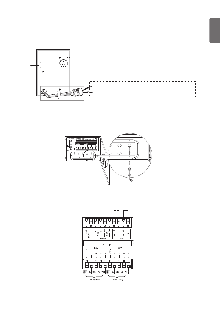
PIPE THERMISTOR CONNECTION
- Check the IN/OUT of the pipe thermistor connected to the AHU
15
ENGLISH
AHU
- Connect the flexible tube and connector (Ø16, installed on the site) from the AHU to the Control
Kit.
- Connect the pipe IN and OUT Thermistor in the EEV module connector.
AHU
Pipe Temperature Sensor IN : Ø 5, Length: 5m, Color: Black
Pipe Temperature Sensor OUT : Ø 7, Length: 5m, Color: Red
Flexible Tube and Connector: Ø 16 (supplied on the site)
Pipe out Thermistor
Pipe in Thermistor
OUTDOOR UNIT COMMUNICATION LINE CONNECTION
16
ENGLISH
OUTDOOR UNIT COMMUNICATION LINE
CONNECTION
Cautions on connecting the EEV module (communication
module) with outdoor unit
- The Control Kit comes mounted with three EEV modules,
and each EEV module can be connected to one Expansion
Kit.
If additional EEV modules are required depending on the
number of outdoor units, they must be purchased
separately and installed.
- Make sure the communication cables of each outdoor unit
and pipe thermistor wires of Expansion Kit are not mixed
when connecting the outdoor units.
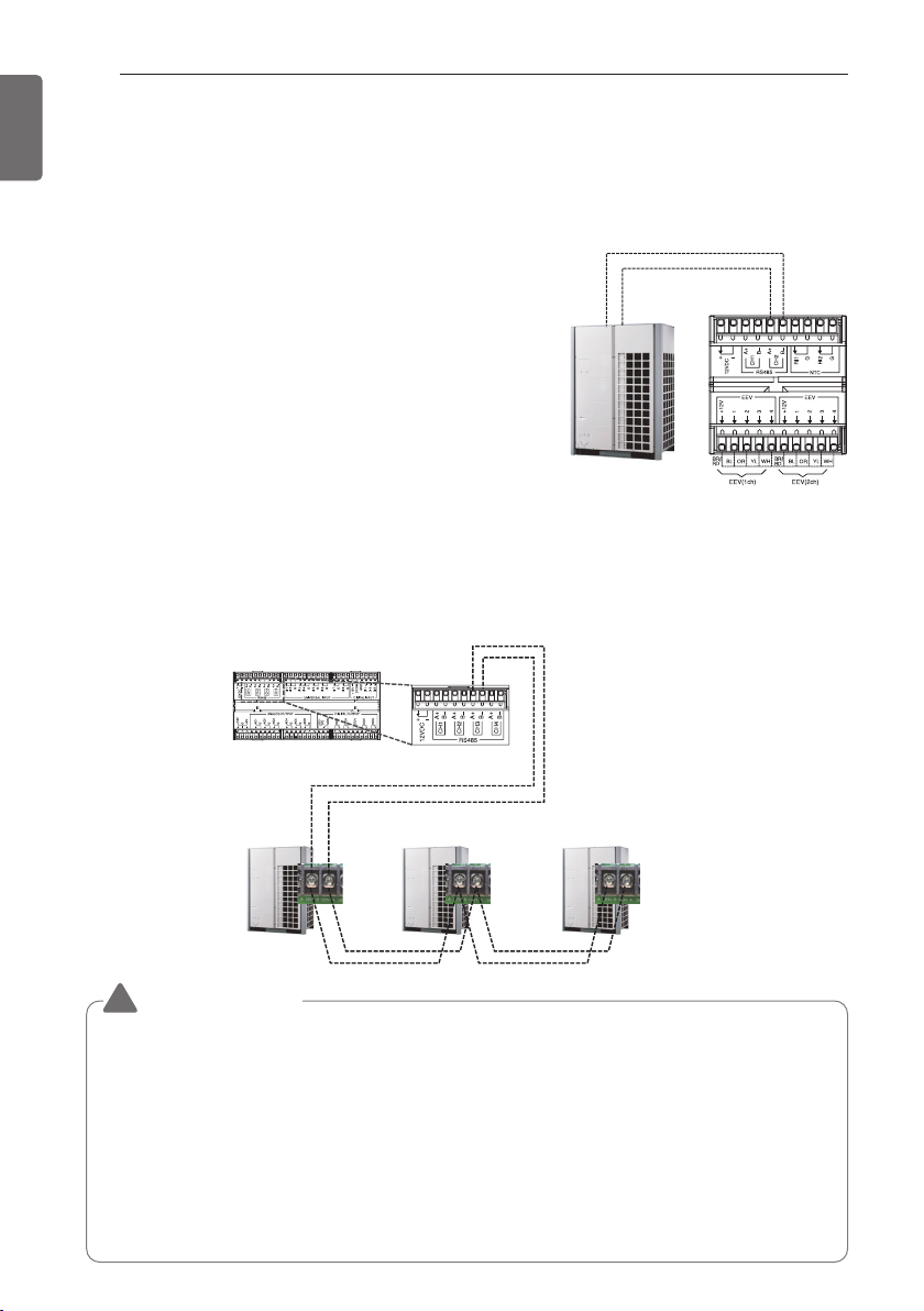
Capacity Control Communication Cable Connection
-
In order to control the SA temperature in the control kit, the central control communication line
must be additionally connected. Please refer to the wiring diagram and the figure below for details.
- For models without a central control communication modem, a central control communication
modem must be installed separately to control the supplied air's temperature.
CH3 A+
CH3 B-
IDU B
IDU A
CH2 B-
CH2 A+
<Main module>
CAUTION
!
Connect
CEN B, CEN A
Outdoor
Unit #1
Connect
CEN B, CEN A
Outdoor
Unit #2
Connect
CEN B, CEN A
Outdoor
Unit #3
• The AHU Control Kit can control the temperature of the supply air by connecting to up to three
outdoor units. When connecting outdoor units, the communication addresses should be set
from 1 to 3, sequentially.
Otherwise, the supply air temperature control function may not work properly.
• Make sure the polarity of the power supply connector is correct when connecting the
communication cable between the Control Kit and outdoor unit.
• DIP SW 3 of the outdoor unit must be turned off in order to ensure communication between the
control kit and the outdoor unit.
• When connecting to Multi V Super 5, Function FN39 must be set to Option1. (Dip switch No.5
ON → FUNC → FN39 → OP1) Please refer to the Multi V manual for details on Multi V Function
settings. (Applicable to both ventilation temperature control and supply air temperature control)
 Loading...