


INSTALLATION/
OWNER’S MANUAL
AIR
CONDITIONER
Please read this installation manual completely before installing the product.
Installation work must be performed in accordance with the national wiring
standards by authorized personnel only.
Please retain this installation manual for future reference after reading it
thoroughly.
HVAC manager (AC Manager IV)
PACM4B000
P/NO : MFL68581202
www.lg.com


Explanatory Notes
i
Explanatory Notes
Copyrights
The contents of this User's Guide for the software AC Manager VI are protected by international
copyright and computer program protection laws. The contents of the User's Guide and the programs
mentioned herein are limited to uses allowed by LG Electronics. The content can only be used and
copied under adherence to the user agreement. You may not reproduce (by any means) or distribute
(by any means) copies of this User's Guide or any part of it without prior approval of LG Electronics.
Copyright © 2014 LG Electronics. All rights reserved.
Registered Trademarks
AC Manager VI is a registered trademark of LG Electronics. All other products and company names
are trademarks of their respective owners and are used for illustrative purposes only.
ENGLISH

Explanatory Notes
AC Manager IV
ACP
AC Manager IV
ii
Product Features
ENGLISH
AC Manager VI Configuration Integrates Easily.
y The integrated device management offers driver management, peak power
control, demand control, and accumulated power divider.
y Status monitoring and control as shown in the plan.
y Operates indoor or outdoor groups on a schedule.
y Provides records of indoor use daily, weekly, or monthly.
y Report feature can be used to generate internal reports.
Other External Equipment Controls
y Works in conjunction with external equipment such as fire alarms, key tags,
and lighting.
y Ability to link with ACP
Efficient Power Control
y Displays and manages the power usage of each room.
y Distributed power data can be saved or printed.
y Ability to control the outdoor unit capacity
Convenient Automation
y Switches between cooling and heating to reach the desired temperature of
users.

Explanatory Notes
How to Use This Guide
Please read from the beginning to the end of this User's Guide before using AC Manager VI. Also
store this guide somewhere easily accessible.
Notations Used In This Guide
Keyboard Notation
• Keyboard strokes used by the system are marked by boldface text in angle brackets (< >).
Example: <Esc> Key
• Key combinations use the same format with the addition of a plus sign (+).
Example: <Ctrl+C> Key
Program UI Notation
• Control buttons displayed within the system are marked by boldface text in square brackets ([ ]).
Example: [OK], [Save]
• Option titles displayed in the program are marked by boldface text.
Example: Start, Programs
iii
ENGLISH

iv
ENGLISH
MEMO

Table of Contents
v
Table of Contents
Important Safety
1
Precautions
Preparation
3
3 Installation
3 – Components
4 – Recommended Specifications
4 – Installing AC Manager VI
18 – Deleting AC Manager VI (Windows 7)
22 Starting and Closing the Program
22 – Starting the Program
24 – Closing the Program
Using the Program
25
25 Home
25 – Screen Configuration and Features
27 Control/Monitoring
27 – Screen Configuration and Features
42 – Device Control
43 – Monitoring Devices
44 – Editing the Floor Plan
46 – Deleting the Floor Plan
48 Schedule
48 – View overall schedule
49 – Creating Schedules
53 – Checking Schedules
55 – Editing Schedules
58 – Copy Schedule
59 – Deleting Schedules
59 – View history
60 – Peak Control
67 – Demand Control
69 – Temperature limit
74 – Auto change over
79 – Time Limit
84 – Device interlock
91 Energy Monitor
91 – Wattage
93 – Gas
95 – Running time
97 Report
97 – Working history
99 – Installation Status
100 Cycle
100 – Outdoor Unit
101 – Chiller
102 Set
102 – Device Setting
119 – System Setting
125 – User Settings
Hint
131
131
AC Manager VI Complete System
Diagram
131 – Connecting AC Manager VI to an
ACP
133 –
134 Pre-Tech Support Checklist
135
Connecting AC Manager VI to multiple
ACPs
LGE Open Source Software Notice
ENGLISH
60 Auto Control

vi
ENGLISH
MEMO
Important Safety Precautions
Important Safety Precautions
The Impor tant Safety Precautions shown in the following are to avoid potential injury or damage due
to unexpected accidents, and to increase the lifetime of the product.
WARNING
If you don't follow the instructions, you could be injured or even killed.
Keep the Lock Key out of reach of children. If a child happens to swallow it, see the doctor
y
immediately.
To prevent electric shock or fire, do not expose the Lock Key to water or humidity.
y
Do not disassemble the Lock Key arbitrarily as it could cause electric shock.
y
The Lock Key does not guarantee any use, which could result in injury or death due to impairment.
y
CAUTION
If you do not follow the instructions, you could have injury or property loss.
The Lock Key could hurt your hands. Please use extreme care when using it.
y
Never remove the Lock Key when you are using AC Manager.
y
1
ENGLISH
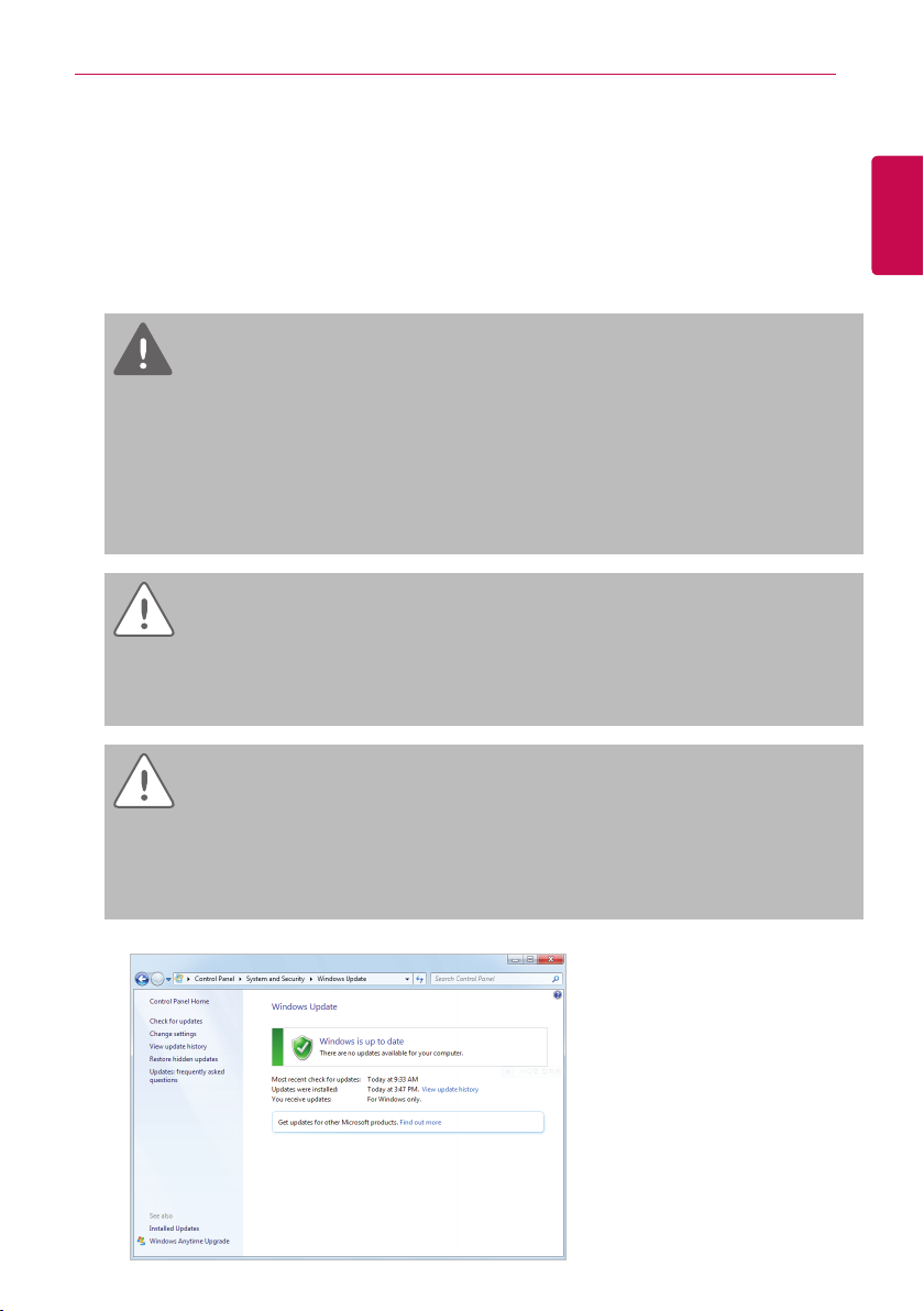
CAUTION
To prevent installation error, Please check the status of your computer Windows.
During Windows Update, if AC Manager VI installation starts, error occurs, and the installation
y
cannot be completed.
How to check: Start>Control Panel>System and Security>Windows Update
y

Important Safety Precautions
2
ENGLISH
MEMO
Preparation
3
Preparation
The section provides the basic information required before using AC Manager VI.
Installation
This section explains the pre-installation preparations for AC Manager VI and how to install it.
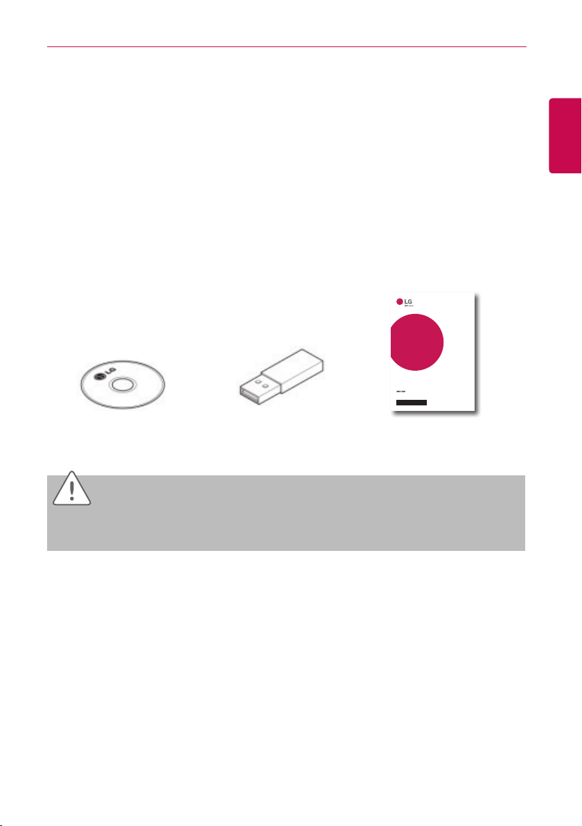
Components
AC Manager VI packaging includes the following components as shown in the diagram. Please open
the AC Manager VI package and verify that all components are included.
INSTALLATION/
OWNER’S MANUAL
AIR
CONDITIONER
Please read this installation manual completely before installing the product.
Installation work must be performed in accordance with the national wiring
standards by authorized personnel only.
Please retain this installation manual for future reference after reading it
thoroughly.
HVAC manager (AC Manager IV)
AC Manager VI
Installation DVD (User's Guide)
CAUTION
USB Authentication Key
(Hard Lock Key)
PACM4B000
P/NO : MFL68581202
www.lg.com
Quick Guide
ENGLISH
If any product is used other than our standard product and a problem occurs, we don't take any
responsibility regarding the problem. Please keep away from using other products.
Preparation
4
Recommended Specifications
The recommended specifications for AC Manager VI are shown here.
ENGLISH
Hardware
CPU Dual Core 2.4GHz or faster
System Memory 4 GB or more
Hard Disk Space 100 GB or more
OS Windows XP/7/8/8.1
Resolution 1280 x 1024 or higher
Recommended
Graphics
ACP ACP version 1.1.4p or higher
VGA: For NVidia, Geforce or later. For ATI, Radeon or later
Installing AC Manager VI
Install AC Manager VI using the procedures outlined in this document.
Hardware Installation
↓
AC Manager VI Software Installation (Client/Server)
Hardware Installation
This section explains how to connect the computer to ACP to use AC Manager VI.
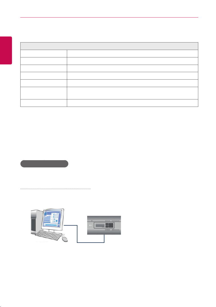
Connecting AC Manager VI to an ACP
Use these steps when installing AC Manager VI and connecting the ACP to the same computer.
1. Connect an Ethernet cross cable to the Ethernet port of the ACP.
ACP
AC Manager IV
LAN (Cross-over Cable)
2. Connect the other end of the Ethernet cross cable to the Ethernet por t of the computer.
• You should only use an Ethernet cross cable if you are connecting the computer
(AC Manager VI) and the ACP without a hub. The ACP Ethernet terminal is located on the
device as shown in the figure.
the computer where AC
Manager VI is installed
Connec t with the hub
Direct Cable
Connect directly with
Cross Cable
NOTES
Do not use the Ethernet cable before checking if it is a direct cable or cross cable. Use the LAN
tester to examine the cable before connecting the cable.
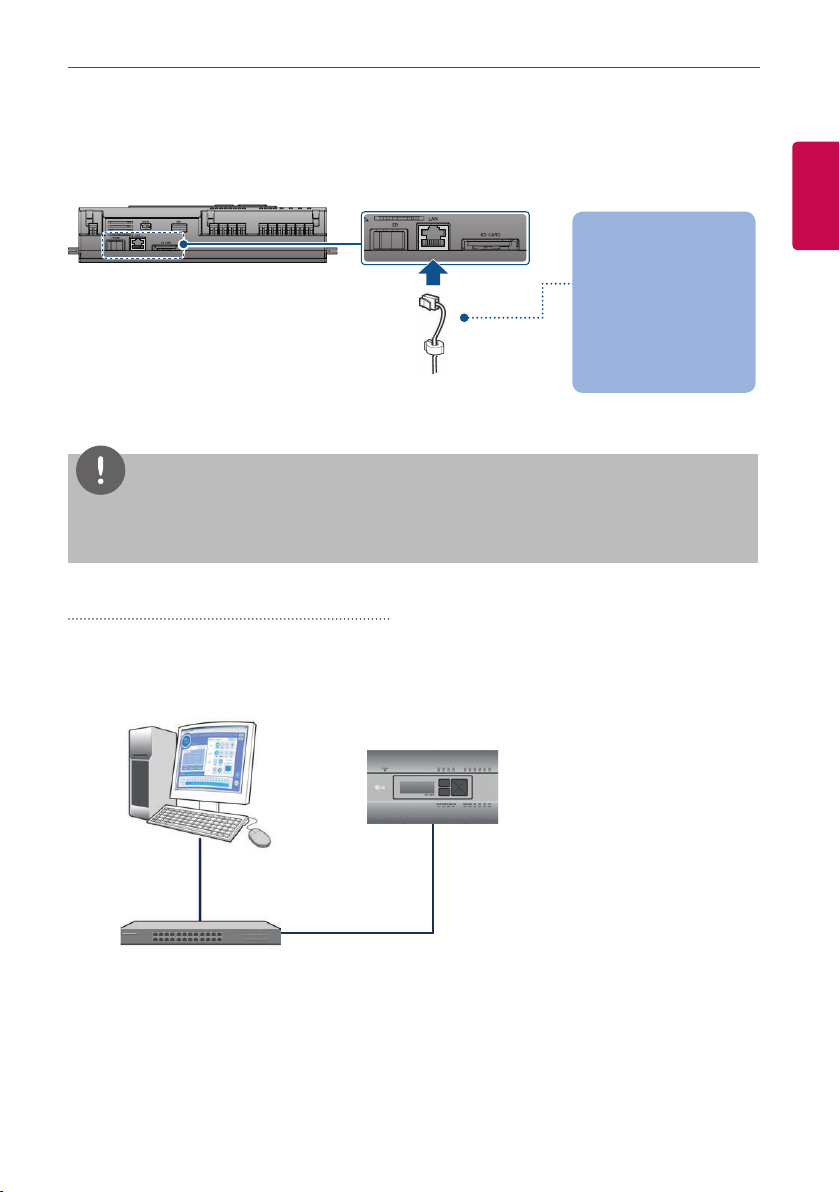
Connecting AC Manager VI to multiple ACPs
Preparation
5
ENGLISH
Use these steps when connecting AC Manager VI to multiple ACPs by using a hub.
1. Connect each ACP to the hub with a standard Ethernet cable.
AC Manager VI
ACP
LAN
(Direct Cable)
Hub
Preparation
6
AC Manager VI software installation(Client)
This section explains how to install AC Manager VI software(Client).
ENGLISH
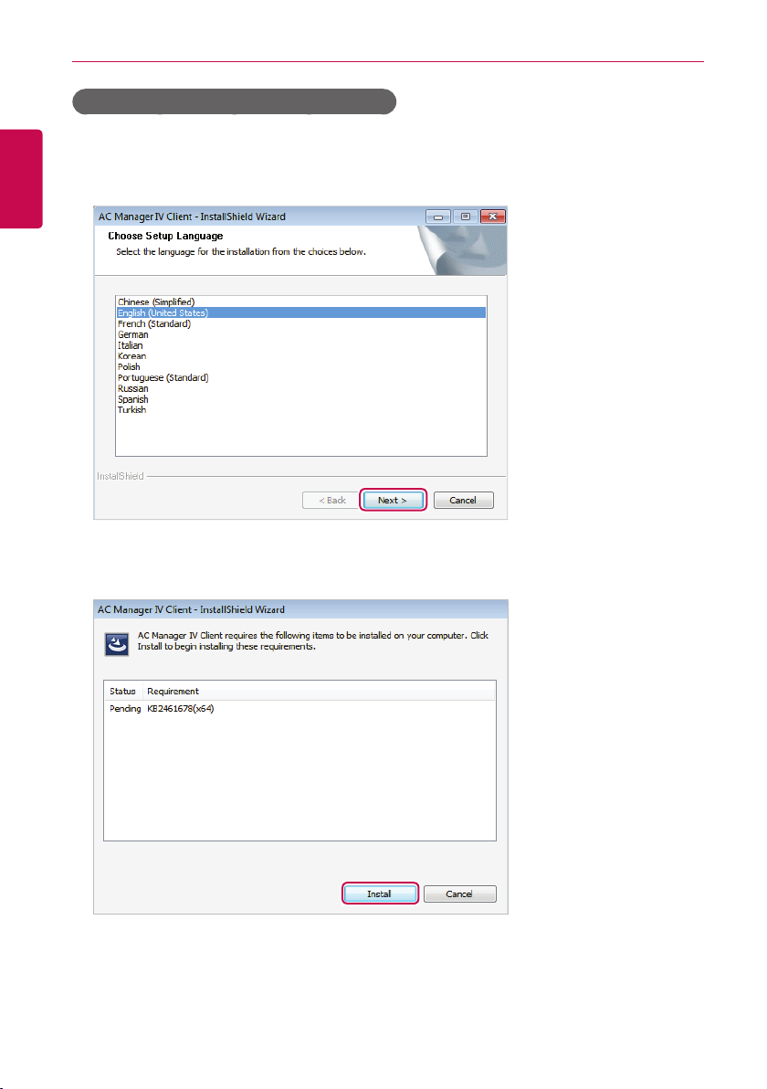
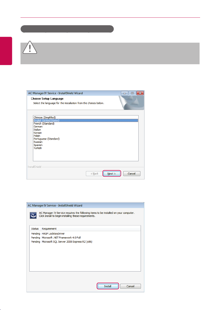
1. Double-click installation file.
2. Select the installation language and click [Next>] button.
3. When the required components installation screen appears, click [Install] button.
• This will begin the installation of the required components.
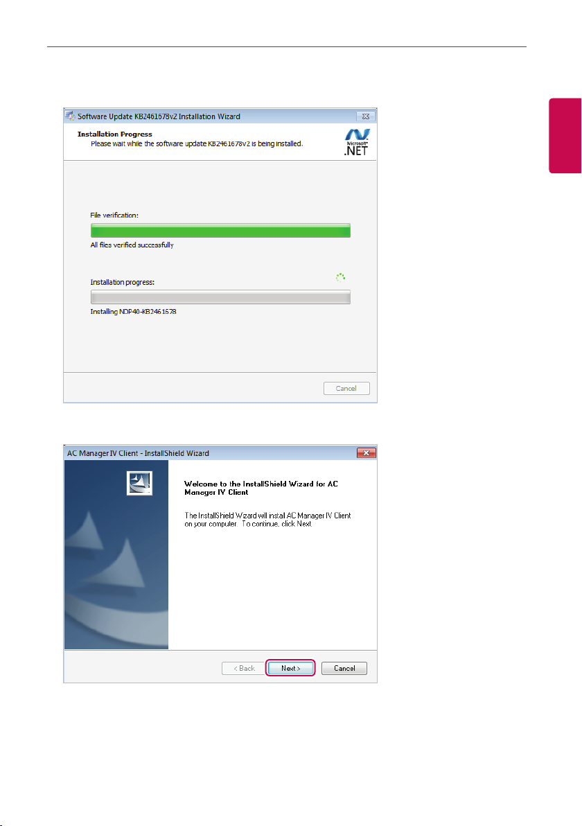
• When the required components installation is complete, AC Manager VI Client installation
program prepares IntallShield Wizard. Please wait.
4. Once the AC Manager VI Client InstallShield Wizard appears, click [Next >] .
Preparation
7
ENGLISH
Preparation
8
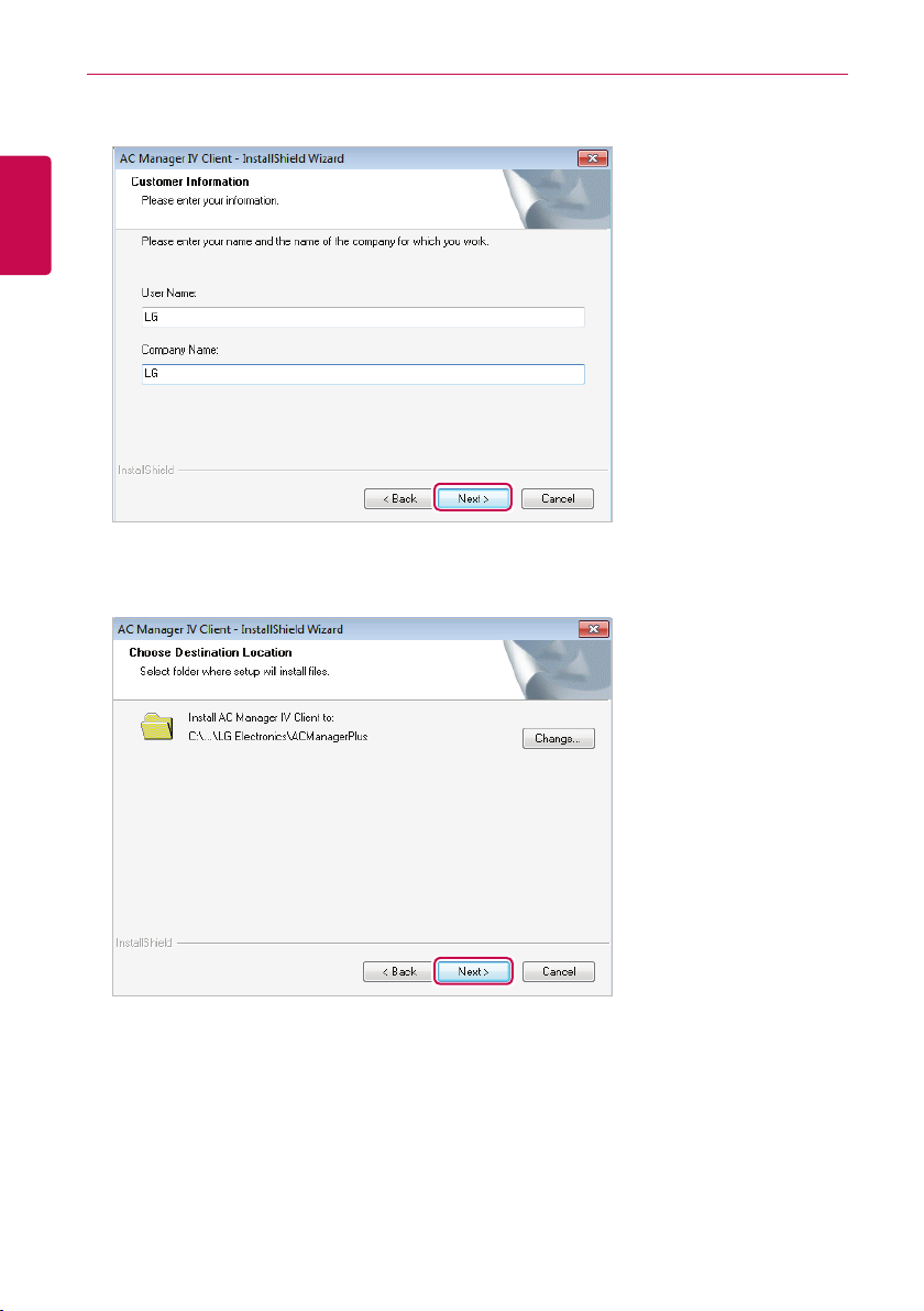
5. Enter the user information and click the [Next >] button.
ENGLISH
6. Confirm the install location of the AC Manager VI Client and click [ Next >].
• If you wish to change the install location, click [Change...] and set the desired location.
Preparation
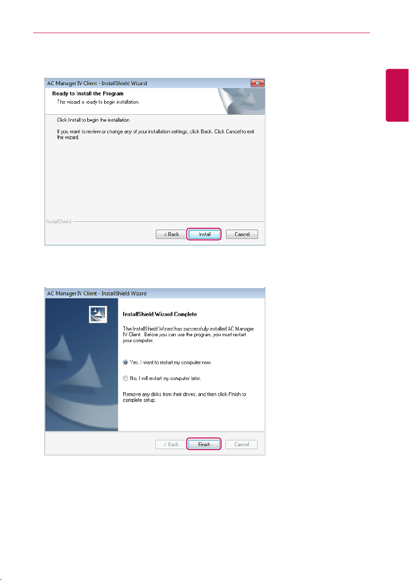
7. To start the installation, click [Install].
• The AC Manager VI Client will now be installed.
8. To restart the program, click "Yes, I want to restart my computer now." and click [Finish] button.
• Program installation is completed.
9
ENGLISH
Preparation
10
AC Manager VI software installation(Server)
ENGLISH
CAUTION
After the software installation is complete, Lock Key must to be inserted.
This section explains how to install AC Manager VI software(Server).
1. Double-click installation file.
2. Select the installation language and click [Next>] button.
3. When the required components installation screen appears, click [Install] button.
• This will begin the installation of the required components.
Preparation
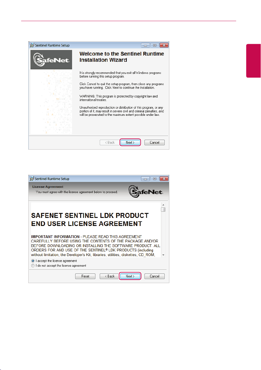
4. When the SafeNet installation screen appears, click [Next >] button.
5. SafeNet License Agreement screen appears, click "I accept the license agreement", and click
[Next >] button.
11
ENGLISH
Preparation
12
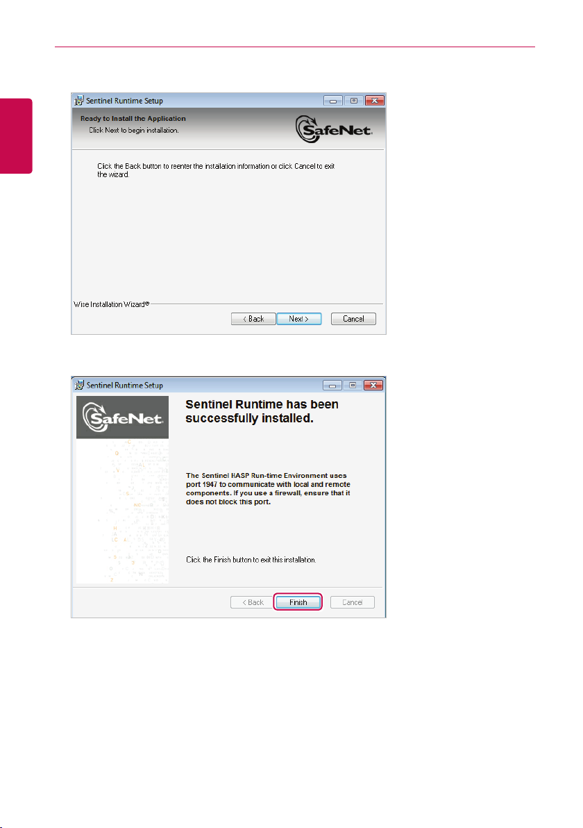
• This will begin the installation.
ENGLISH
6. When the installation is complete, click [Finish] button.
Preparation
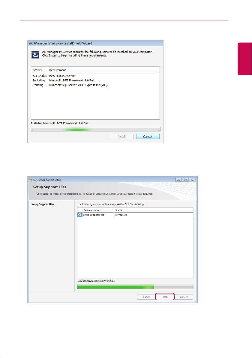
• This will start the installation of the following required components.
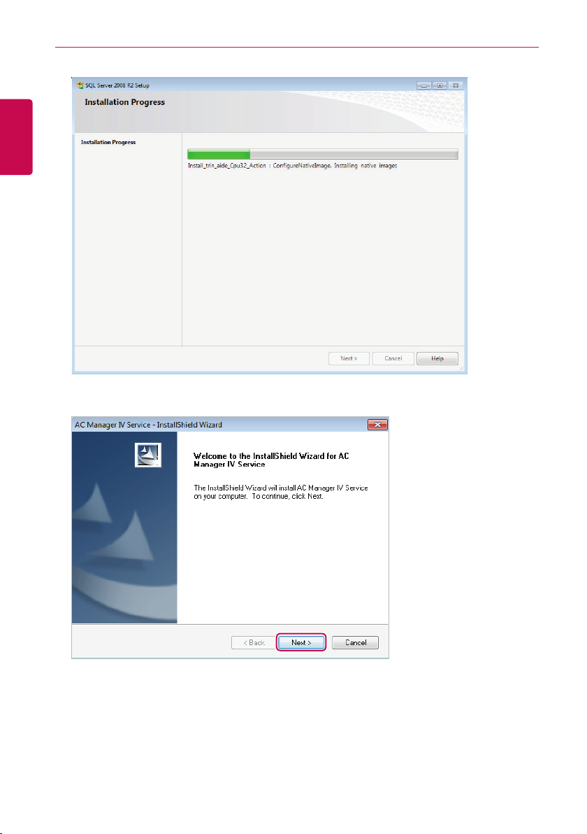
7. When Microsoft SQL Server 2008 Express R2 installation screen appears, click [Install] button.
• When the required components installation is complete, AC Manager VI Ser ver installation
program prepares IntallShield Wizard. Please wait.
13
ENGLISH
Preparation
14
ENGLISH
8. When AC Manager VI Service IntallShield Wizard screen appears, click [Next(N)>] button.
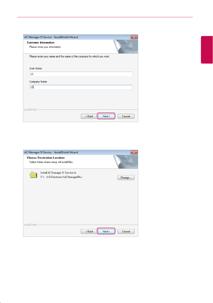
9. Input user information, and click [Next(N)>] button.
10. Check AC Manager VI Ser vice installation location, and click [Next(N)>] button.
• To change installation location, click [Change(C)…] button, and designate the desired
installation location.
Preparation
15
ENGLISH
Preparation
16
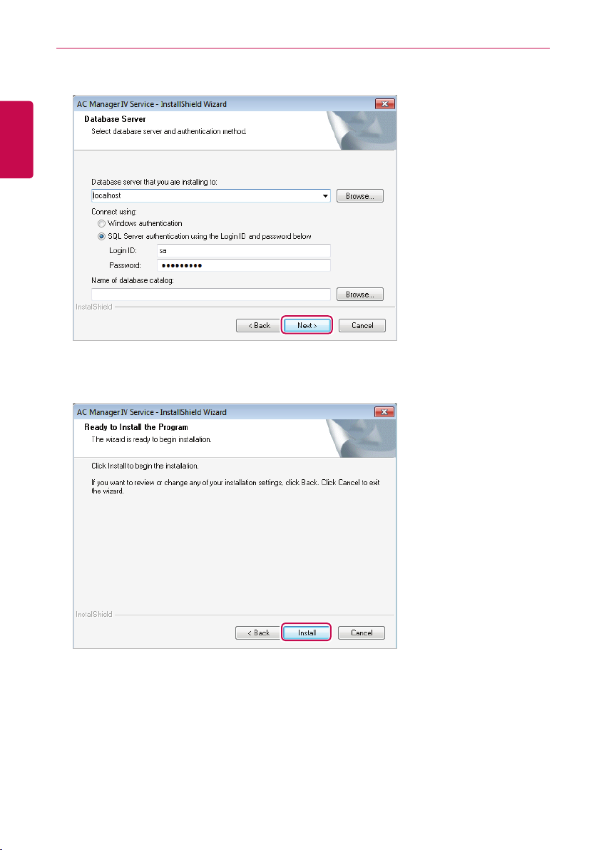
11. Set the database server and authentication method, and click [Next(N)>] button.
ENGLISH
12. To start the installation, click [installation(I)] button.
• This will start AC Manager VI Service installation.
Preparation
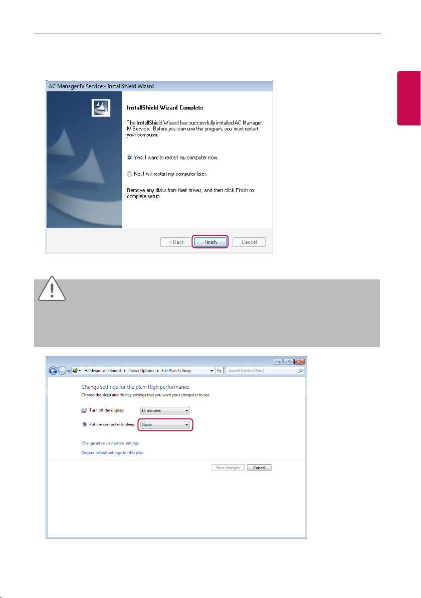
13. To restart the program, click "Yes, I want to restar t my computer now." and click [Finish] button.
• Program installation is completed.
CAUTION
Check if the power saving mode of the computer is set.
In Start>Control Panel>Hardware and Sound>Power Option>Change the time for the computer to
y
switch to power saving mode, change the power saving mode to ‘Never’.
17
ENGLISH
Preparation
18
Deleting AC Manager VI (Windows 7)
This section explains how to delete AC Manager VI.
ENGLISH
Delete AC Manager VI software(Client)
This section explains how to delete AC Manager VI software(Client).
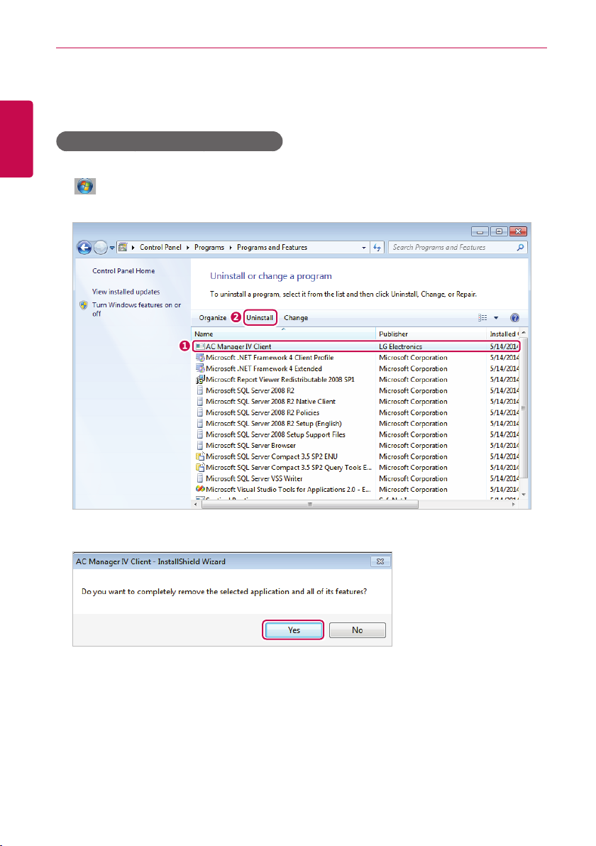
1. > Control Panel > Programs > Programs and Features.
2. In the Uninstall or change a program window, highlight AC Manager VI Client and click [Uninstall].
3. When you are prompted to confirm the removal, click [Yes].
Preparation
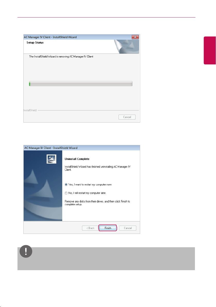
• This will start the removal.
4. To restart the program, click "Yes, I want to restart my computer now." and click [Finish] button.
• This will finish the program removal.
19
ENGLISH
NOTES
If you delete AC Manager VI, all data will also be deleted.
Preparation
20
Delete AC Manager VI software(Server)
This section explains how to delete AC Manager VI software(Server).
ENGLISH
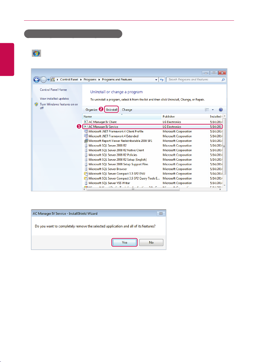
1. > Control Panel > Programs > Programs and Features.
2. In the Uninstall or change a program window, highlight AC Manager VI Server and click [Uninstall].
3. When you are prompted to confirm the removal, click [Yes].

Preparation
• This will start the removal.
4. To restart the program, click "Yes, I want to restart my computer now." and click [Finish] button.
• This will finish the program removal.
21
ENGLISH
NOTES
If you delete AC Manager VI, all data will also be deleted.
Preparation
22
Starting and Closing the Program
ENGLISH
This section explains how to star t and close AC Manager VI.
Starting the Program
This section explains how to star t AC Manager VI.
1. Connect the authentication key to a USB port on the computer with AC Manager VI.
• If you attempt to start the program without the authentication key attached, a warning appears.
Insert the authentication key and start the program again.
NOTES
All functions of AC Manager VI are determined by the approval of the authentication key. Do not
y
remove the authentication key from the computer while operating AC Manager VI.
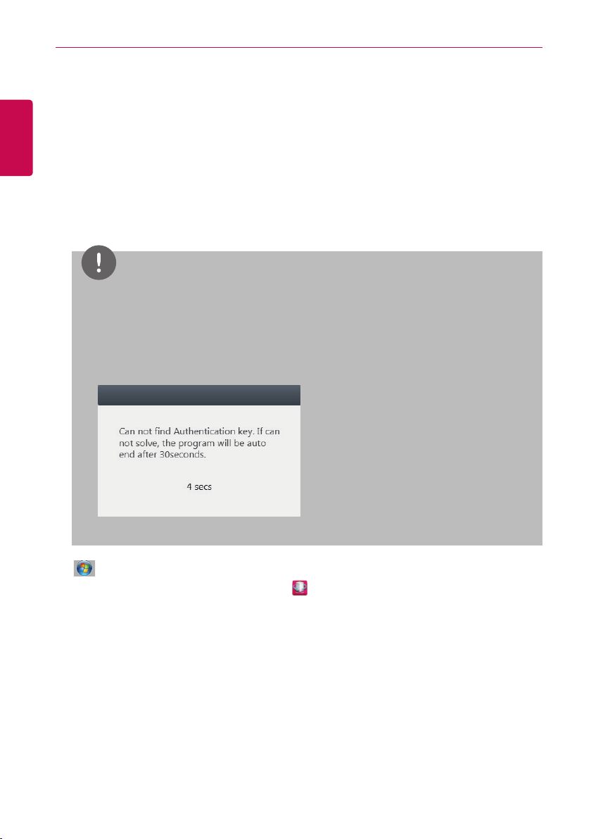
If the authentication key is removed while operating the program, the following warning message
y
pop ups. If you insert the authentication within 30 seconds, the warning window is turned off and
the program begins to operate normally.
2. > All Programs > LG Electronics > AC Manager VI Client > Executing AC Manager VI.
• Alternatively, double-click the shortcut icon
• AC Manager VI Program will start.
on your desktop.
3. In the login window, click [Enter ser ver information].

4. After entering the server's IP address, click [Save].
• This IP address may vary depending on which computer you are logging in from. If this is the
server PC, enter the loopback address (127.0.0.1). If this is a client PC, enter the IP address of
the server PC.
5. After entering your ID and password in the login window, click [Login].
Preparation
23
ENGLISH

Preparation
24
Closing the Program
You can exit and close AC Manager VI as follows.
ENGLISH
1. From the AC Manager VI program, click the [X] in the right top corner.

Using the Program
25
Using the Program
This section explains how to use AC Manager VI.
Home
You can check operation status of the devices installed to AC Manager VI, today’s schedule, and
whether automatic control is applied. You can also control start /stop of all indoor units.
Screen Configuration and Features
This section explains the Home screen configuration and features.
①
②
ENGLISH
③
No. Item Description
①
Operation Run/Stop of all indoor units
④

Using the Program
26
ENGLISH
No. Item Description
y Overall operation status
- Check operation status(run/stop/error) of the devices installed to
AC Manager VI
Operation status
②
Today’s schedule View up to 5 schedules list
③
④
Automatic
control
- Classify by the number of the devices
y Status by each management group
- Check status of each management group designated by the user
y Status by each location group
- Check status of each location group designated by the user
Whether it is in automatic control operation

Using the Program
Control/Monitoring
This section explains how to control the device and monitor the control status of the device.
Screen Configuration and Features
The screen configuration and features of the Control/Monitoring menu screen are as follows.
①
27
ENGLISH
②
No. Item
Too l b a r s
①
Device List Tab
②
Content Display
③
Summary Display
④
③
④

Using the Program
28
Toolbars
This section explains the toolbars of the Control/Monitoring menu.
ENGLISH
①
②
③
④
No. Item Description
AC Manager VI Menu
①
Toolbox Controls
②
③
④
Apply/Cancel Changes in the control status triggers this.
Content Filter Button
Tab
Service Menu for AC Manager VI.
Changes according to devices attached and other variables.
(For more information, refer to the Toolbox Controls per
Device on page 30.)
Allows you to filter content in the Content Display area by
device type or status. Click the boxes of each filter to see or
hide the corresponding content.
y
: Show active devices.
y
: Show inactive devices.
y
: Show devices with a schedule.
y
: Show devices controlled by peak and demand.
y
: Show devices with errors.
y
: Show devices in need of a filter replacement.
y
: Show devices with lock settings.
y : Show Oil Alarm devices.
y
: Show indoor devices.
y
: Show devices with ventilators or direct expansions.
y
: Show AHU devices.
y
: Show AWHP / Hydro kit devices.
y
: Show Chiller devices.
y
: Show On/Off devices.
y
: Show DI devices.
y
: Show DO devices.
y : Show AI devices.
y
: Show AO devices.
⑤
⑥
⑦

Using the Program
No. Item Description
y Shows the number of devices with errors.
⑤
⑥
⑦
Error Alarm
Sort Selection
Button to see by each
device icon type
y When selected, it changes to Report > Working
history.
y By name: Sorts the devices by their names.
y By address: Sorts the devices by their addresses.
y By device: Sorts by equipment type.
y Whether running: Sorts by status; "On", "Error", or
"O ff".
Adjust the size of the device viewing icon appearing in the
contents area
y
: View list
y
: View small list
y
: View normal list
y
: View big list
NOTES
If the error code is displayed on the AC Manager VI, please double click to view the details for
description of the error.
29
ENGLISH

Using the Program
30
Toolbox Controls per Device
registered device, the menu of the toolbox controls may dif fer. The following explains the toolbox
ENGLISH
controls per device.
NOTES
The exact control limit for a device may differ from the actual device. Please be sure to refer to the
manual for the device.
■ Indoor Device
Item Description
Run
Running mode
Temperature Click [▲]/[▼] to set the temperature.
Fan
y [Run] Button: Starts the operation of the device.
y [Stop] Button: Stops the operation of the device.
y [Auto] Button: Changes to Auto Mode.
y [Cool] Button: Changes to Cooling Mode.
y [Heat] Button: Changes to Heating Mode.
y [Dr y] Button: Dehumidifies during rainy seasons or whenever
humidity is high. You cannot set the temperature in this mode.
y [Fan] Button: Purifies the air. You cannot set the temperature in this
mode.
y Fan: Selects the fan speed.
- [Auto] Button: Loops from Low to Medium to High
- [High] Button: Fast fan speed.
- [Mid]: Medium fan speed.
- [Low] Button: Slow fan speed.
y Swing [Set/Cancel] Button: Turn on or off automatic oscillation of
the fan.

Item Description
y All [Lock/Cancel] Button: Enables/disables remote control for all
features.
y Mode [Lock/Cancel] Button: Enables/disables remote control for
Lock
mode selection.
y Temperature [Lock/Cancel] Button: Enables/disables remote
control for temperature setting.
y Fan speed [Lock/Cancel] Button: Enables/disables remote control
for fans.
Using the Program
31
ENGLISH
Limit temp.
Operation detail
setting
Click [▲] /[▼] to set the temperature limit. This prevents a user from
setting the indoor temperature outside the defined range.
y Auto change over: It is the function to automatically change over to
cooling operation when indoor temperature is over the upper limit
temperature, and to heating operation when indoor temperature is
below the lower limit temperature. (It is only supported by cooling/
heating dual function outdoor unit.)
- [Run] button: Set automatic change over.
- [Stop] button: Reset automatic change over.
y Lower: Touch [▲] /[▼] button to set lower limit temperature (18 °C~30
°C).
y Upper: Touch [▲] /[▼] button to set upper limit temperature (18 °C~30
°C).
y Temperature limit: It is the function to maintain the temperature of the
space where the device is installed within certain boundary. (It is only
supported by cooling/heating dual function outdoor unit.)
- [Run] button: Set temperature limit.
- [Stop] button: Reset temperature limit.
y Cool Start: Touch [▲] /[▼] button to set cooling operation star t
temperature (21 °C~40 °C).
y Heat Star t: Touch [▲] /[▼] button to set heating operation start
temperature (1 °C~20 °C).

Using the Program
32
ENGLISH
■ Ventilator or Direct Expansion Ventilator
Item Description
Run
Running mode
Temperature
Fan speed
Air Conditioner
Additional
function
Lock
y [Run] Button: Starts the operation of the device.
y [Stop] Button: Stops the operation of the device.
y [Auto] Button: Changes to Auto Mode.
y [Heat exchange] Button: Air supply and emissions are all ventilated
through the heat exchanger.
y [Normal] Button: Ventilate emissions without passing through the
heat exchanger.
(Only applicable to the Direct Expansion Ventilator.)
Click [▲] /[▼] to set the temperature.
y Auto : Loops from Low to High to Very High.
- Users cannot select this mode.
- When set to sleep/rapid mode, fans are automatically set to Auto
mode.
- When sleep/rapid mode is disabled, fans are automatically set to
High.
- Sleep/rapid mode is disabled if Very High, High, or Low is se
lected while Auto operation mode is active.
y Super High: Maximum fan speed.
y High: Fast fan speed.
y Low: Slow fan speed.
(Only applicable to the Direct Expansion Ventilator.)
y [Off ] Button: Disables air conditioning for the Direct Expansion
Ven til ato r.
y [Cool] Button: Changes to cooling mode.
y [Auto] Button: Automatically changes the mode based on indoor
conditions.
y [Heat] Button: Changes to heating mode.
y Quick [Set/Cancel] Button: Turns Rapid feature on/off. (If Rapid is
enabled, Sleep is disabled.)
y Humidifier [Set/Cancel] Button: Turns the Humidify feature on/off.
(Only when Air Conditioning is in Heating mode.)
y Power save [Set/Cancel] Button: Turns Sleep mode on/off. (If
Sleep is enabled, Rapid is disabled.)
y Heater [Set/Cancel] Button: Turns the Heater feature on/off.
All [Lock/Cancel] Button: Enables/disables remote control for all features.
-

■ AHU
Item Description
Run
Easy control
Running mode
Temperature Click [▲] /[▼] to set the temperature.
Additional
function
Set
y [Run] Button: Starts the operation of the device.
y [Stop] Button: Stops the operation of the device.
Press [Easy control ▼] button to add/edit/delete easy control mode (user
mo de).
y You can set up to 4 easy control modes.
y The control commands applied as the set easy control mode are not
saved in the control tool box.
y [Cool] Button: Changes to Cooling Mode.
y [Heat] Button: Changes to Heating Mode.
y [Fan] Button: Purifies the air. You cannot set the temperature in this
mode.
y Additional options will appear under Operating Modes after
registering an AHU.
- [Power save] Button: Reduces energy consumption by operating
in the most ef ficient way. Emission air is greater than air supply to
emit remove air from indoors more ef fectively.
- [Dry] Button: Dehumidifies during rainy seasons or whenever
humidity is high. You cannot set the temperature in this mode.
y These options only show when add-ons for the AHU are installed.
y Auto Ventilation [Set/Cancel] Button: Turns Automatic Ventilation on/
off.
y Humidifier [Set/Cancel] Button: Turns Humidification on/off.
y CO₂: Use [▲] /[▼] to set the desired carbon dioxide emissions from 500
ppm to 1 500 ppm in intervals of 100 ppm.(CO₂ is only settable in Auto
Vent)
y Humidity: Use [▲] /[▼] to set the desired humidity from 40 % to 60
% in intervals of 5 % (the humidify is only settable in the humidity
setting.
Using the Program
33
ENGLISH

Using the Program
34
ENGLISH
Item Description
y Outdoor Air: Use [▲]/[▼] to set the air intake damper opening
value from 0 to 90 SDgr in intervals of 1SDgr.
y Exhaust Air: Use [▲] /[▼] to set the emission damper opening value
from 0 to 90 SDgr in intervals of 1SDgr.
Degree of
opening damper
Lock
y Mixed Air: Use [▲]/[▼] to set the mixer damper opening value from
0 to 90SDgr in intervals of 1SDgr (the damper opening value is only
settable in the Cooling/Heating Fan modes).
*Set > System Settings > Basic Setting >
If 'Setting Damper' button is 'Set', it is operate<Outdoor Air(OA)=Exhaust
Air(EA), Outdoor Air(OA)+Mixed Air(MIX)=90>
All [Lock/Cancel] Button: Enables/disables remote control for all
features.
■ AWHP / Hydro kit
Item Description
Run
Running mode
Outlet water
temperature*
Air Te m p .*
Hot water
Hot water temp. Click [▲] /[▼] to set the water heater temperature.
Lock
y [Run] Button: Starts the operation of the device.
y [Stop] Button: Stops the operation of the device.
y [Auto] Button: Changes to Auto Mode.
y [Cool] Button: Changes to Cooling Mode.
y [Heat] Button: Changes to Heating Mode.
(Only operates on Cooling/Heating modes.)
y Water temperature setting for underfloor cooling and heating.
y Click [▲] /[▼] to set the temperature for Cooling and Heating modes.
(Only operates on Cooling/Heating modes.)
Click [▲] /[▼] to set the indoor air temperature.
y [Run] Button: Start hot water operation.
y [Stop] Button: Stop hot water operation.
All [Lock/Cancel]: Enables/disables remote control for all features.
* When setting the AWHP device, the selected temperature is shown. (Refer to AWHP on page 108)

Using the Program
35
NOTES
Chiller is optional feature, it can not be supported.
■ Scroll chiller
Item Description
Run
Alarm [Cancel] button: Reset alarm in the device.
Running mode
Temperature
Demand control Press [▲]/[▼] button to set demand limit ratio.
■ Screw chiller
y [Run] Button: Starts the operation of the device.
y [Stop] Button: Stops the operation of the device.
(It is only shown when the device supports the corresponding mode.)
y [Cool] button: Change over to cooling mode.
y [Heat] button: Change over to heating mode.
y Set load water outlet temperature for indoor cooling/heating.
y Press [▲] /[▼] button to set cooling mode and heating mode
temperatures.
ENGLISH
Item Description
Run
Alarm [Cancel] button: Reset alarm in the device
Running mode
Temperature
Motor running
current limit value
y [Run] Button: Starts the operation of the device.
y [Stop] Button: Stops the operation of the device.
Operation mode cannot be controlled. Control of the set temperature of
the monitored operation mode.
y Set load water outlet temperature for indoor cooling/ice making.
y Press [▲] /[▼] button to set cooling mode and ice making mode
temperatures.
Press [▲] /[▼] button to set motor current limit ratio.

Using the Program
36
ENGLISH
■ Turbo chiller
Item Description
Run
Alarm [Cancel] button: Reset alarm in the device.
Running mode
Temperature
Motor running
current limit value
y [Run] Button: Starts the operation of the device.
y [Stop] Button: Stops the operation of the device.
Operation mode cannot be controlled. Control of the set temperature of
the monitored operation mode.
y Set load water outlet temperature for indoor cooling/heating/ice
making.
y Press [▲] /[▼] button to set cooling mode and heating/ice making
mode temperatures.
Press [▲] /[▼] button to set motor current limit ratio.
■ Absorb chiller
Item Description
Run
Alarm [Cancel] button: Reset alarm in the device
Running mode
Temperature
Control Valve
Upper Limit
y [Run] Button: Starts the operation of the device.
y [Stop] Button: Stops the operation of the device.
Operation mode cannot be controlled. Control of the set temperature of
the monitored operation mode.
y Set load water outlet temperature for indoor cooling/heating.
y Press [▲]/[▼] button to set cooling mode and heating mode
temperatures.
Press [▲] /[▼] button to set control valve upper limit ratio.

■ On/Off device
Item Description
Run
y [Run] Button: Starts the operation of the device.
y [Stop] Button: Stops the operation of the device.
■ DI
Item Description
Run
y [Short Circuit] Button: Short signal output.
y [Open] Button: Open signal output.
■ DO
Using the Program
37
ENGLISH
Item Description
Run
y [Short Circuit] Button: Short signal output.
y [Open] Button: Open signal output.
■ AI
Item Description
Temperature Press [▲] /[▼] button to set the desired temperature.

Using the Program
38
ENGLISH
■ AO
Item Description
Temperature Press [▲] /[▼] button to set the desired temperature.
NOTES
Control tool box text and unit are shown variably for ACS I/O devices according to the usage setting.

Device List Tab
Using the Program
39
Explains the Tab of Device List.
① ② ③ ④
ENGLISH
No. Item Description
Management List of management devices for user convenience.
①
Location
②
Installation Provides information on all connected devices.
③
Multi-side
④
y A floor plan showing control and management for each device.
y Includes a mini-map.
y A list sorted into three groups: Devices, Status, and Other.
y Displays histories based on the selected items.

Using the Program
40
Content Display
The setting status of a device is displayed as follows.
ENGLISH
①
②
③
No. Item Description
Group Display
①
②
Installed
Device Count
Displays the management group name, number of active devices,
number of installed devices and number of errored devices.
Displays the number of installed devices in each group. (Set or Cancel
this under Set.)
y Large icon
①
②
③
④
① Device status icon
② Device icon / operation status
③ Current temp / current temp / operation
mode
④ Device address
③
Content
Details
y Medium icon
①
②
③
y Small icon
y List: Displays all attributes of the devices in the group.
① Device status icon
② Device icon / operation status
③ Current temp / current temp / operation
mode
Device icon / operation status / operation
mode

Content Display Icons
Device Status Icons
Using the Program
41
ENGLISH
Icon
Enlarge / Normal Small
- Schedule control
- Peak control
- Replace filter
- Lock all
-
Summary Display
①
②
No. Item Description
Use status Shows the current status of the selected device.
①
Working
②
history
Shows the operation history of the device.
Status
Oil alarm

Using the Program
42
Device Control
You can control the registered device by setting it to the desired state.
ENGLISH
1. In the menu bar at the top, click Control/Monitoring.
2. Click the desired tab in the Device List.
Item Description
Management List of management devices for user convenience.
Location
Installation
Multi-side
3. Select the device you wish to manage in the list.
• You can control multiple devices at the same time. Drag selected devices to the Content
Display. Hold <Ctrl> to individually select multiple devices. If you want to choose all devices
in a group, check the check box for the selected group. Depending on the types of devices
chosen, the control box is limited.
4. Use the Toolbox to set the control state of the selected device.
5. When you have completed making changes, click [Apply] .
y A floor plan showing control and management for each device.
y Includes a mini-map.
Provides information on all connected devices.
y A list sorted into three groups: Devices, Status, and Other.
y Displays histories based on the selected items.

Monitoring Devices
You can check the control state of registered devices.
1. In the menu bar at the top, click Control/Monitoring.
2. Click the desired tab in the Device List.
3. Click the filter button of the device type or status in the Content Display.
• Multiple filters can be selected, excluding
• Select the content information of the corresponding part.
Item Description
Show active devices( cannot select with)
Show inactive devices( cannot select with)
Show devices with a schedule.
Show devices controlled by peak and demand.
Show devices with errors.
Show devices in need of a filter replacement.
Show devices with lock settings.
Show Oil Alarm devices.
Show indoor devices.
or .
Using the Program
43
ENGLISH
Show devices with ventilators or direct expansions.
Show AHU devices.
Show AWHP / Hydro kit devices.
Show Chiller devices.
Show On/Off devices.
Show DI devices.
Show DO devices.
Show AI devices.
Show AO devices.
4. Please see the device information in the Content Display.
• You can reduce/enlarge the size of the device icons with the slider.
5. To set the control status details of a device, double-click its icon.
• This moves you to the detailed information display of the selected device.
6. If you want to return to the monitoring screen, click the device list or click [Go to Main menu].

Using the Program
44
Editing the Floor Plan
You may edit the floor plan by selecting the Location tab in the Control/Monitoring menu.
ENGLISH
1. In the menu bar at the top, click Control/Monitoring.
2. Click the Location tab in the Device List.
• The floor plan opens.
3. Click [Editing] button.
4. The floor plan editor opens.

Using the Program
5. To add a floor plan, click [Floor plan add].
6. If the file import window appears, select the floor plan file you wish to use and click [Open].
• The selected image will appear in the floor plan editor.
7. To add a device to the floor plan, select the device in the device list and drag it onto the floor
plan.
8. To add or edit text on the floor plan, use the Enter Text control in the Toolbox.
Item Description
y Tex t : Inserts a text box into the floor plan.
y Font: Click [▼] to select the desired font from a list.
y Font size: Click [▼] to select the desired font from a list.
Enter Text
y Bold: Change the text to boldface.
y Color: Select the desired font color from a palette.
y Larger: Increases the font size by 1 pt.
y Smaller: Decreases the font size by 1 pt.
9. When you have completed making changes, click [Apply] .
10. To move to the main floor plan screen, click [drawing View].
45
ENGLISH
NOTES
To add a floor plan, you can only use jpg, bmp or png format.
y
To add a floor plan, 2MB or less image size is recommended. If the size is exceeded, the alarm
y
popup appears.

Using the Program
46
Deleting the Floor Plan
You can delete the added floor plan.
ENGLISH
1. In the menu bar at the top, click Control/Monitoring.
2. Click the Location tab in the Device List.
• The floor plan opens.
3. Click [Editing] button.
• The floor plan editor opens.

4. To delete a floor plan, click [Delete drawing].
• The floor plan is deleted.
Using the Program
47
ENGLISH

Using the Program
48
Schedule
ENGLISH
The Schedule feature allows you to program the behavior of the devices. If a device must adhere to a
certain schedule, you can program the device to operate only at scheduled times. Scheduled devices
do not activate unless programmed to do so and are managed centrally. This can significantly reduce
energy consumption.
View overall schedule
You can see the list of the items in all schedules set in AC Manager VI.
You can check whether the set schedule is applied, name, repetition dates, start date, end date, and
device list. When you select the desired schedule, the summary information is shown at the bottom.
You can also immediately apply or reset the desired schedule.

Creating Schedules
Follow these steps to add a schedule.
1. In the menu bar at the top, click Schedule.
2. From the Toolbox, click [New schedule].
• The new schedule screen opens.
Using the Program
49
ENGLISH
①
②
③
No. Item Description
①
②
③
Name & Schedule
Exception date Manage exception days.
Device List
Set the schedule name, start date, end date, and days of
operation.
y Displays information on registered devices.
y [Edit device] Button: Add or delete a device.
④

Using the Program
50
No. Item Description
ENGLISH
④
Events
3. Enter a name for the schedule in the window.
4. Select repeat dates to repeat the schedule.
Item Description
Once
Select day of week
y Create events for the selected device.
y Entering Times
- Click [▲] /[▼] to set the time.
- Valid entries are in the 00:00 - 23:50 range in 10
minute intervals.
y Device Settings
- The available device tabs depend on the device
selected in the Device List. Use these controls to set
behavior.
y [Add event] Button: Create an additional event.
y
Button: Copies the current event.
Button: Deletes the current event.
y
y Apply the schedule on the star t date and no other days.
y You cannot specif y repeat days with this setting.
y You can not select an end date.
Select the desired day of week to repeat only on the corresponding
day of week from the start date to the end date.
5. Set the desired period
Item Description
Start date
End dates
End date is not
designated
y Select the desired start date from the mini calendar.
y Default start date is selected as the today’s date.
y Select the last day of operation. Click the date to open a
calendar.
y You cannot set the end date as the same or previous date from
the start date.
This schedule repeats until ended manually.
6. To set exception dates, click [Load saved data].
• The exception dates are imported from the system settings and displayed.
7. To manually add new exception dates, click and select the exception dates to add.
8. Add an exception name in the name box.

Using the Program
9. In the Device List, click [Edit device].
• The edit device window opens.
10. In the unregistered devices list, click the group that the device you want to regsister belongs to
and click [◀] button.
• To regester multiple groups at a time, tick the checkbox for the groups you want to register and
click [◀] button.
• The selected devices are added to the device list.
51
ENGLISH
NOTES
If you register Exp.I/O devices of the different types, a warning message "You cannot register
Exp.I/O devices of the different types at the same type." appears for 3 seconds and
disappears.
11. After registering a device, click [Save].
12. To add a new event, click [Add event].
13. In the Events list, use [▲] /[▼] to set the desired time, then select the control status.
NOTES
Click button to copy the previously set schedule event except time. The setup time interval for
an event should be 10 minuites or longer.
14. When you have completed making changes, click [Apply] .

Using the Program
52
Setting Exceptions
You can import and edit the exception dates that are already set in the system. You can also add
ENGLISH
additional exception dates.
Importing Exceptions
You can import the exception dates that are already set in the system, as follows.
1. In the Schedule screen, click [Load saved data].
• The exception dates are imported from the system settings and displayed.
2. To save these settings, click [Apply].
Adding or Deleting Exceptions
You can add or delete exception dates as desired, as follows.
1. Add or delete exceptions dates from the Schedule screen.
①
②
③
No. Item Description
①
②
③
Delete All Delete all listed exception dates.
Delete Selected Delete the selected exception date.
y Add an additional exception date.
Add Exception
Select exception dates to add by clicking →
y
Enter a name for the exception in the input box.
2. To save these settings, click [Apply].

Checking Schedules
Follow these steps to check a schedule.
1. In the menu bar at the top, click Schedule.
• The schedule screen opens.
Using the Program
53
ENGLISH
①
②
No. Item Description
①
②
③
Dates
Event Display
Summary
y Shows the date currently displayed below.
y Click [◀]/[▶] to change the currently displayed date.
y Check the box to show the selected schedule.
y Schedules are shown by color, date, and name ( You cannot
manually set the schedule color).
y A summary of the selected schedule.
y Provides information about the schedule name, duration,
repeats, and devices.
y Displays settings according to time.
2. Select the date to display on the calendar or in the Toolbox.
③

Using the Program
54
3. Select a viewing mode to see the schedule.
ENGLISH
Item Description
Day View
Week View
Month View
4. Select the schedule item you wish to see from the schedule list.
• To select multiple schedules, check the box at the beginning of the list.
• The settings screen for the selected schedules appears.
5. If you want to batch star t the selected schedules, click [Star t All]. To batch stop the selected
schedules, click [Stop All].
• To start a single schedule, click
.
• To save the schedule settings as a file, click [Save as file] . When the file save screen
appears, enter a file name and click [Save].
• To print the schedule, click [Print].
by the schedule name. To stop a running schedule, click

Editing Schedules
You can change the settings for schedules that are currently listed.
1. In the menu bar at the top, click Schedule.
Using the Program
55
ENGLISH
2. Select the schedule you wish to modif y from the list.
3. Click [Edit].
• The schedule screen opens.

Using the Program
56
ENGLISH
①
②
③
④
No. Item Description
①
②
③
Name & Schedule
Exceptions
Device List
Modify the schedule name, start date, end date, and
days of operation.
Manage exception days.
y [Load saved data] Button: Impor t a list of
exception dates from system settings.
y Displays information on registered devices.
y [Edit device] Button: Add or delete a device.

No. Item Description
y Create events for the selected device.
y Entering Times
- Click [▲] /[▼] to set the time.
- Valid entries are in the 00:00 - 23:50 range in 10
minute intervals.
④
Events
y Device Settings
- The available device tabs depend on the device
selected in the Device List. Use these controls to
set behavior.
y [Add event] Button: Create an additional event.
y
Button: Copies the current event.
Button: Deletes the current event.
y
4. Modify the desired schedule.
5. When you have completed making changes, click [Apply] .
Using the Program
57
ENGLISH

Using the Program
58
Copy Schedule
You can copy of Schedule.
ENGLISH
1. In the menu bar at the top, click Schedule.
2. Select a schedule from the list , please copy the schedule.
3. From the toolbar area, click the button [Copy schedule].
4. When the confirm pop -up window appears, click [OK].
• A list of the selected schedule will be copied.

Deleting Schedules
Follow these steps to delete a schedule.
1. In the menu bar at the top, click Schedule.
2. Select the schedule to delete in the schedule list.
3. From the Toolbox, click [Delete].
4. When you are prompted to confirm the deletion, click [OK].
• The selected schedule is then deleted and removed from the list.
View history
View a history of scheduled activity in this log.
1. In the menu bar at the top, click Schedule.
2. From the Toolbox, click [View history].
• The log report appears.
Using the Program
59
ENGLISH
3. To save the log as a file, click [Save as file]. When the file save screen appears, enter a file
name and click [Save].
4. To print the log, click [Print].

Using the Program
60
Auto Control
ENGLISH
Auto control allows you to change power consumption or control external devices by linking to them.
You can also set the indoor temperature to automatically change according to outdoor conditions or
activate devices for certain periods of time.
NOTES
If you change the control value of the device in the Auto Control mode, the existing Auto Control
y
values are cancelled.
Chiller is not in automatic control linkage .
y
When you change the group information of the automatic control, Automatic control > Peak/
y
Demand control information is initialized.
Peak Control
Peak control limits the peak power consumption. You can set the target operating rate so that the
total power consumption does not exceed this limit. To prevent power consumption from exceeding
the limit, the system will automatically change cooling mode to fan mode and cancel heating mode.
1. In the menu bar at the top, click Auto control.
2. From the Toolbox, click [Peak control].
• The peak control screen opens.
①
②

No. Item Description
y Run
- [Apply peak control] Button: Activates peak control for the
selected ACP.
- [Cancel peak control] Button: Deactivates peak control for the
selected ACP.
y Control Methods
- Outdoor unit capacity control function: Applies limits to outdoor
units to control outdoor limits.
- Priority Control: Applies limits according to the priority of each
AC P.
y Operation rate Bar
- This graphical bar shows the current operation rate and the target
operation rate of indoor units.
- You can drag the triangle slider(
rate.
y Current operation rate (%)
- Shows the percentage of currently operating units from all entire
indoor ACP units (blue bar).
y Target operation rate (%)
- Click [▲] /[▼] to set the desired operation rate (green bar).
y Operation Change over time (Minutes)
- Click [▲] /[▼] to set the time in minutes to force operation to stop.
- You can set this from 5 to 15 minutes.
Shows device name, activity, current temperature, set temperature, and
operation mode.
)to change the target operation
①
②
Control Info
Display
Operation
Status
Using the Program
61
ENGLISH
3. Select the ACP you wish to control from this list.
• The ACP settings are then shown to the right of the list.
4. Select the control status in the control status display.
5. To apply control settings, click [Apply].
• The control settings are then saved.
6. To activate the selected group, click [Apply peak control] or next to the group name.
• To deactivate the group, click [Cancel peak control] or
next to the group name.
7. To apply all peak controls to registered ACPs, click [Apply to all]. To disable all peak controls,
click [Cancel all].

Using the Program
62
ENGLISH
NOTES
Depending on the installation site specifications, either of the peak control and demand control can be
y
selected. Go to Set > System setting > Basic setting. In Select peak/demand controll select a
desired control method.
The peak control is only limited to the indoor device and you can not register other devices such as
y
ventilator or AHU, except a indoor device.
Editing Groups
Follow these steps to change group settings at the bottom of the ACP.
1. In the menu bar at the top, click Auto control.
2. From the Toolbox, click [Peak control] and select an ACP.
3. Click [Edit].
• The peak control group edit screen opens.
①
②
③
④
No. Item Description
①
②
③
④
Grou p Ta b s All registered groups are shown as tabs.
Group Name Enter or modify the group name in this textbox.
Group Priority
[Edit device]
Button
Choose the priority of the group: Ver y low, Low, Normal, High,
Very high
Opens a window to edit the device list (add or remove).
⑤

Using the Program
No. Item Description
⑤
Device List Displays a list of devices registered in the selected group.
4. You can group multiple outdoor units together, or add or delete specific units from a group. Edit
the selected group to your desired preferences.
• For details about grouping outdoor units, refer to Applying to Outdoor Units on page 63.
• For details about adding groups, refer to Adding Groups on page <OV>.
• For details about deleting groups, refer to Deleting Groups on page 65.
5. To apply control settings, click [Apply].
• The control settings are then saved.
Applying to Outdoor Units
You can group multiple outdoor units (registered in ACP) together.
1. To apply settings to outdoor units registered to the ACP, click [Apply by outdoor unit].
• Peak control is applied to that group.
63
ENGLISH
2. To save these settings, click [Apply].
NOTES
If outdoor unit is applied, previously created group will be deleted.

Using the Program
64
Adding Groups
Follow these steps to add a new group.
ENGLISH
1. To add a group, click [Add group].
• The add group screen opens.
2. Enter a name for the group in the group name textbox.
3. Set the priority of the group.
4. To add a device, click [Edit d evice].
• The edit device screen opens.
5. Check the box of unregistered devices you wish to add and click [◀].
• You can only add indoor units for peak control.
• To add multiple devices at one time, check multiple boxes before clicking [◀].
• The selected devices are added to the device list.
NOTES
A device that does not belong to the group cannot be registered.
6. To accept changes to the list, click [Save].
7. To save these settings, click [Apply].

Deleting Groups
Using the Program
65
Follow these steps to delete a group from the group list.
1. Click the [X] on the tab of the group you wish to delete.
• The selected group is deleted and the tab removed.
2. To save these settings, click [Apply].
Viewing the Status of Peak Controls
Follow these steps to view the status of current peak controls.
1. In the menu bar at the top, click Auto control.
2. From the tool box, click [Peak control] button.
3. From the control list, click [View peak control status] button.
• Peak control status viewing screen appears.
ENGLISH
①
No. Item Description
y Control Method
①
Control Info
Display
- Priority Control: Switch to control by priority.
- Outdoor unit capacity control function: Switch to control by
outdoor units.
②

Using the Program
66
ENGLISH
No. Item Description
(Control method when priority control is selected)
y Shows a status list of peak controls for each ACP.
- Priority peak control status: Graphical display of current
operation rates and target operation rates for each ACP.
- Current operation rate (%): Displays the current operation rate
of each ACP (blue bar).
②
Peak Control
List
- Target operation rate (%): Displays the target operation rate of
each ACP (green bar).
(Control method when outdoor unit control is selected)
y Displays a capacity control list for outdoor units on each ACP.
- Outdoor unit capacity peak control status: Displays the
target operation rate (%).
- Target Operation rate (%): Displays target operation rate for
outdoor units on each ACP.

Using the Program
Demand Control
After observing changes in power consumption, this feature can prevent power consumption from
exceeding a set limit. If you set the demand control and the program predicts that power consumption
will exceed the limit, it will begin deactivating less important devices to save energy.
1. In the menu bar at the top, click Auto control.
2. From the Toolbox, click [Demand control].
• The demand control screen opens.
①
②
67
ENGLISH
No. Item Description
y Control Method
- Outdoor unit capacity control: Switches to a screen that
offers controls based on the outdoor unit capacity limit.
- Priority control: Switches to a screen that offers controls
based on ACP Group Priority.
①
Operation Status
②
Control Info
Display
y Operation rate bar: This graphical bar shows the current
operation rate and the target operation rate of indoor units.
y Current operation rate (%)
- Shows the percentage of currently operating units from all
entire indoor ACP units (blue bar).
y Target operation rate (%)
- Displays the target operation rate (green bar).
Shows device name, activity, current temperature, set
temperature, and operation mode.

Using the Program
68
3. Select an ACP group to see its control status.
ENGLISH
• You can check the demand control status in the control information display and the operation
status list.
NOTES
Depending on the installation site specifications, either of the peak control and demand control can
y
be selected. Go to Set > System setting > Basic setting. In Select peak/demand controll select
a desired control method.
You can check the demand control status and edit groups in the demand control menu. But you can
y
not set the target operation rate, switchover, Activity Controls, and Apply All/Disable All.

Temperature limit
The temperature limit feature allows you to maintain a certain temperature range.
1. In the menu bar at the top, click Auto control.
2. From the Toolbox, click [Temperature limit].
• The temperature limit screen opens.
No. Item Description
y Run
- Apply: Activate the selected group.
- Cancel: Deactivate the selected group.
y Set temp.
Control Info
①
②
Display
Control List Displays a list of each registered devices and its current status.
- Low limit temperature: The lowest temperature that is allowed
aindoors.
- Upper limit temperature: The highest temperature that is
allowed indoors.
y Temperature referenc: Displays the method of measuring the
indoor temperature.
- Average of all devices: The average temperature of readings
from all indoor devices.
Using the Program
69
ENGLISH
①
②
3. Select the group to apply temperature limits to in the group list.
• The control settings status of the selected group opens.
4. To activate the selected group, click [Apply] or the next to the group name.
• To deactivate the selected group, click [Cancel] or
next to the group name.
5. To batch star t all groups, click [Apply to all]. To batch stop all groups, click [Cancel All].

Using the Program
70
Adding Groups
Follow these steps to add a new group.
ENGLISH
1. In the menu bar at the top, click Auto control.
2. From the Toolbox, click [Temperature limit], then click [New group].
• The add group screen opens.
①
②
③
No. Item Description
Group Name Enter or modify the group name in this textbox.
①
y Low limit temperature: Use [▲]/[▼] to set the possible
②
③
Set temp.
Device List
lowest indoor temperature.
y Upper limit temperature: Use [▲]/[▼] to set the possible
highest indoor temperature.
y Displays information on registered devices.
y [Edit device] Button: Add or delete a device.
3. Enter a name for the group in the group name textbox.
4. Click [▲]/[▼] to set the low and high temperature limits.
5. To add a device, click [Edit device].
• The edit device window opens.

6. Check the box of unregistered devices you wish to add and click [◀].
• You can only apply temperature limits to indoor units.
• To add multiple devices at one time, check multiple boxes before clicking [◀].
• The selected devices are added to the device list.
7. After registering a device, click [Save].
8. To save these settings, click [Apply].
Using the Program
71
ENGLISH

Using the Program
72
Editing Groups
Follow these steps to change group settings.
ENGLISH
1. In the menu bar at the top, click Auto control.
2. From the Toolbox, click [Temperature limit].
• The temperature limit screen opens.
3. Select the group to modify in the group list, then click [Edit] in the Toolbox.
• The edit group screen opens.
①
②
③
No. Item Description
Group Name Enter or modify the group name in this textbox.
①
y Low limit temperature: Use [▲]/[▼] to set the possible
②
③
Set temp.
Device List
lowest indoor temperature.
y Upper limit temperature: Use [▲]/[▼] to set the possible
highest indoor temperature.
y Displays information on registered devices.
y [Edit device] Button: Add or delete a device.
4. Edit the selected controls to your desired preferences.
5. To save these settings, click [Apply].

Deleting Groups
Using the Program
73
Follow these steps to delete a group from the group list.
1. In the menu bar at the top, click Auto control.
2. From the Toolbox, click [Temperature limit].
• The temperature limit screen opens.
3. Select the group to delete from the list and click [Delete] in the Toolbox.
4. When you are prompted to confirm the deletion, click [OK].
• The selected group is deleted and removed from the list.
ENGLISH

Using the Program
74
Auto change over
If the temperature exceeds the high limit, the cooling system activates. If it falls below the low limit,
ENGLISH
the heating system activates.
1. In the menu bar at the top, click Auto control.
2. From the Toolbox, click [Auto change over].
• The auto switchover screen opens.
①
②
No. Item Description
y Run
- Apply: Activate the selected group.
- Cancel: Deactivate the selected group.
y Set temp.
Control Info
①
②
Display
Control List Displays a list of each registered devices and its current status.
- Standard temperature: Shows the currently set indoor tem
perature.
- Temperature difference: Shows the current temperature dif
ference from the set temperature.
y Temperature reference: Displays the method of measuring the
indoor temperature.
- All of all devices: The average temperature of readings from
all indoor devices.
3. Select the group to apply auto switchover to in the group list.
• The control settings status of the selected group opens.
-
-

Using the Program
4. To activate the selected group, click [Apply] or the next to the group name.
• To deactivate the selected group, click [Cancel] or
next to the group name.
5. To batch star t all groups, click [Apply to all]. To batch stop all groups, click [Cancel all].
Adding Groups
Follow these steps to add a new group.
1. In the menu bar at the top, click Auto control.
2. From the Toolbox, click [Auto change over], then click [New group].
• The add group screen opens.
75
ENGLISH
①
②
③
No. Item Description
Group Name Enter or modify the group name in this textbox.
①
y Standard temperature: Use [▲]/[▼] to set an allowable
②
③
Set temp.
Device List
indoor temperature.
y Temperature difference: Use [▲]/[▼] to set the
temperature change range.
y Displays information on registered devices.
y [Edit device] Button: Add or delete a device.
3. Enter a name for the group in the group name textbox.
4. Click [▲]/[▼] to set the difference from the reference temperature.
5. To add a device, click [Edit device].
• The edit device window opens.

Using the Program
76
6. Check the box of unregistered devices you wish to add and click [◀].
ENGLISH
• You can only apply auto switchover to indoor units.
• To add multiple devices at one time, check multiple boxes before clicking [◀].
• The selected devices are added to the device list.
7. After registering a device, click [Save].
8. To save these settings, click [Apply].

Editing Groups
Using the Program
77
Follow these steps to change group settings.
1. In the menu bar at the top, click Auto control.
2. From the Toolbox, click [Auto change over].
• The auto switchover screen opens.
3. Select the group to modify in the group list, then click [Edit] in the Toolbox.
• The edit group screen opens.
ENGLISH
①
②
③
No. Item Description
Group Name Enter or modify the group name in this textbox.
①
y Standard temperature: Use [▲]/[▼] to set an allowable
②
③
Set temp.
Device List
indoor temperature.
y Temperature difference: Use [▲]/[▼] to set the
temperature change range.
y Displays information on registered devices.
y [Edit device] Button: Add or delete a device.
4. Edit the selected controls to your desired preferences.
5. To save these settings, click [Apply].

Using the Program
78
Deleting Groups
ENGLISH
Follow these steps to delete a group from the group list.
1. In the menu bar at the top, click Auto control.
2. From the Toolbox, click [Auto change over].
• The auto switchover screen opens.
3. Select the group to delete from the list and click [Delete] in the Toolbox.
4. When you are prompted to confirm the deletion, click [OK].
• The selected group is deleted and removed from the list.

Time Limit
You can set limits on when devices will function.
1. In the menu bar at the top, click Auto control.
2. In the Toolbox, click [Time Limit].
• The time limit screen opens.
Using the Program
79
ENGLISH
①
②
No. Item Description
y Run
- Apply: Activate the selected group.
Control Info
①
②
Display
Control List Displays a list of each registered devices and its current status.
- Cancel: Deactivate the selected group.
y Continuous operation time: Displays continuous operation time.
y Apply to day of week: Displays the days when the time limit is
enforced.
3. Select a group from the list.
• The control settings status of the selected group opens.
4. To activate the selected group, click [Apply] or the next to the group name.
• To deactivate the selected group, click [Cancel] or
next to the group name.
5. To batch star t all groups, click [Apply to all]. To batch stop all groups, click [Cancel all].

Using the Program
80
Adding Groups
Follow these steps to add a new group.
ENGLISH
1. In the menu bar at the top, click Auto control.
2. From the Toolbox, click [Time Limit], then click [New group].
• The add group screen opens.
①
②
③
No. Item Description
①
②
③
Group Name Enter a name for the group.
y Continuous operation time: Click [▼] to select the
allowed uptime (1 - 4 hours).
Set Time
Device List
y Apply to day of week: Click the boxes to select which
days have the time limit enforced. (You can select
overlapping days.)
y Displays information on registered devices.
y [Edit device] Button: Add or delete a device.
3. Enter a name for the group in the group name textbox.
4. Click [▼] to select the allowed uptime.
5. Click on the boxes to select which days the limit is enforced.

Using the Program
6. To add a device, click [Edit device].
• The edit device window opens.
7. Check the box of unregistered devices you wish to add and click [◀].
• You can use time limit control on all devices except AHU, AWHP, Hydro kit, DI, DO and ON/
OFF.
• To add multiple devices at one time, check multiple boxes before clicking [◀].
• The selected devices are added to the device list.
8. After registering a device, click [Save].
9. To save these settings, click [Apply].
81
ENGLISH

Using the Program
82
Editing Groups
Follow these steps to change group settings.
ENGLISH
1. In the menu bar at the top, click Auto control.
2. In the Toolbox, click [Time Limit].
• The time limit screen opens.
3. Select the group to modify in the group list, then click [Edit] in the Toolbox.
• The edit group screen opens.
①
②
③
No. Item Description
①
②
③
Group Name Enter or modify the group name in this textbox.
y Continuous operation time: Click [▼] to select the
allowed uptime (1 - 4 hours).
Set Time
Device List
y Apply to day of week: Click the boxes to select which
days have the time limit enforced.
(You can select overlapping days.)
y Displays information on registered devices.
y [Edit device] Button: Add or delete a device.
4. Edit the selected controls to your desired preferences.
5. To save these settings, click [Apply].

Deleting Groups
Using the Program
83
Follow these steps to delete a group from the group list.
1. In the menu bar at the top, click Auto control.
2. In the Toolbox, click [Time Limit].
• The time limit screen opens.
3. Select the group to delete from the list and click [Delete] in the Toolbox.
4. When you are prompted to confirm the deletion, click [OK].
• The selected group is deleted and removed from the list.
ENGLISH

Using the Program
84
Device interlock
You can integrate the system with external devices, such as firealarms, to halt operation of all indoor
ENGLISH
units and ventilators.
1. In the menu bar at the top, click Auto control.
2. From the Toolbox, click [Device interlock].
• The device integration screen opens.
①
②
No. Item Description
①
②
Control Info
Display
Control List
y Run
- Apply: Activate the selected group.
- Cancel: Deactivate the selected group.
y Shows input and output conditions for each action.
y Displays the list of registered devices in the group.
3. Select a group from the group list to integrate with an external device.
• The control settings status of the selected group opens.
4. To activate the selected group, click [Apply] or the next to the group name.
• To deactivate the selected group, click [Cancel] or
next to the group name.
5. To batch star t all groups, click [Apply to all]. To batch stop all groups, click [Cancel all].

Adding Groups
Using the Program
85
Follow these steps to add a new group.
1. In the menu bar at the top, click Auto control.
2. From the Toolbox, click [Device interlock], then click [New group].
• The add group screen opens.
① ②
③
④
⑤
⑥
⑦
ENGLISH
⑧
④

Using the Program
86
ENGLISH
No. Item Description
①
②
③
④
⑤
⑥
⑦
⑧
Group Name Enter a name for the group.
y General pattern
- Pattern that runs output control demand when the input
conditions are met.
y Copy pattern
- Pattern that output device follows the input device state as
it is.
Select pattern type
Input/Output Tabs Inputs and outputs are separated into individual tabs.
Integration
Conditions
Send e-mail
[Edit device] Button Add or delete a device.
[Select all] button Select all device list.
Device List Displays a list of input or output devices.
Control Toolbox
- You can add only 1 device to the input condition, and only
the device with the same attributes with the added input
device is registered.
y Emergency pattern
- Pattern that is recognized as emergency situation when the
input conditions are met.
- Emergency icon is displayed next to the emergency pattern
name to indicate emergency situation.
(When input group setting tab is selected)
Allows you to select a logical operator for the listed conditions.
y AND: Same condition for all devices.
y OR: Matches device condition for 1 or more device.
(When output group setting tab is selected)
When check box is selected, if the corresponding event is run
in ACP, whether the event occurred is sent to the e-mail set in
System setting > error notice setting > Receiving e-mail
address.
(ACP needs to be connected to internet network that can send
e-mail, and it is a function not supported by old type ACP.)
Shows settings for input/output activity on each device.
y Changes according to devices attached and other
variables. (for more details, refer to Toolbox Controls
per Device on page 30 )
3. Enter a name for the group in the group name textbox.
4. Select pattern type.
5. Select the Input Settings tab and define the conditions for device integration.

6. To add a device, click [Edit device].
• The edit device window opens.
7. Check the box of unregistered devices you wish to add and click [◀].
• To add multiple devices at one time, check multiple boxes before clicking [◀].
• The selected devices are added to the device list.
8. After registering a device, click [Save].
9. Select the control status that you want in the Toolbox.
10. Select output group setting tab, and select whether to send e-mail.
11. Carry out No. 6~ 9 procedures again one by one.
12. To save these settings, click [Apply].
Using the Program
87
ENGLISH
NOTES
In old type ACP, device interfaced copy pattern function, emergency pattern function, and individual
y
setting will not work.
In old type ACP, devices except indoor unit only support input error/run and output operation
y
functions.
In old type ACP, input ribbon condition only supports indoor unit’s 'current temperature = not selected
y
+ standard value' combination.

Using the Program
88
Editing Groups
Follow these steps to change group settings.
ENGLISH
1. In the menu bar at the top, click Auto control.
2. From the Toolbox, click [Device interlock].
• The device integration screen opens.
3. Select the group to modify in the group list, then click [Edit] in the Toolbox.
• The edit group screen opens.
① ②
③
④
⑤
⑥
⑦
⑧
④

No. Item Description
①
②
③
④
⑤
⑥
⑦
⑧
Group Name Enter a name for the group.
y General pattern
- Pattern that runs output control demand when the input
conditions are met.
y Copy pattern
- Pattern that output device follows the input device state as
it is.
Select pattern type
Input/Output Tabs Inputs and outputs are separated into individual tabs.
Integration
Conditions
Send e-mail
[Edit device] Button Add or delete a device.
[Select all] button Select all device list
Device List Displays a list of input or output devices.
Control Toolbox
- You can add only 1 device to the input condition, and only
the device with the same attributes with the added input
device is registered.
y Emergency pattern
- Pattern that is recognized as emergency situation when the
input conditions are met.
- Emergency icon is displayed next to the emergency pattern
name to indicate emergency situation.
(When input group setting tab is selected)
Allows you to select a logical operator for the listed conditions.
y AND: Same condition for all devices.
y OR: Matches device condition for 1 or more device.
(When output group setting tab is selected)
When check box is selected, if the corresponding event is run
in ACP, whether the event occurred is sent to the e-mail set in
System setting > error notice setting > Receiving e-mail
address.
(ACP needs to be connected to internet network that can send
e-mail, and it is a function not supported by old type ACP.)
Shows settings for input/output activity on each device.
y Changes according to devices attached and other
variables. (for more details, refer to Toolbox Controls
per Device on page 30 )
Using the Program
89
ENGLISH
4. Edit the selected controls to your desired preferences.
5. To save these settings, click [Apply].

Using the Program
90
Deleting Groups
Follow these steps to delete a group from the group list.
ENGLISH
1. In the menu bar at the top, click Auto control.
2. From the Toolbox, click [Device interlock].
• The device integration screen opens.
3. Select the group to delete from the list and click [Delete] in the Toolbox.
4. When you are prompted to confirm the deletion, click [OK].
• The selected group is deleted and removed from the list.

Using the Program
Energy Monitor
This section explains how to check the device’s power consumption, gas usage amount, or operation
hours with monitor value and graph.
Wattage
You can check the power consumption of each group, the power consumption of an indoor unit, and
total power consumption.
1. In the menu bar at the top, click Energy monitor.
2. From the Toolbox, click [Wattage].
91
ENGLISH
①
No. Item Description
Power Consumption
①
②
History Graph
Energy Monitor
Details
y Displays the selected time period.
y Displays cumulative and average consumption.
y Displays history vs current for cumulative and average.
Provides detailed power consumption for the registered indoor
units.
②

Using the Program
92
3. Set the time period in the Toolbox.
ENGLISH
Item Description
Time Scale
Set base date
4. To view these settings, click [Apply].
• The power consumption for the selected period appears.
• To save the inquiry as a file, click [Save as file] . When the file save screen appears, enter a
file name and click [Save].
• To export the queried content to an email, press [Export to Email] button.
- If the administrator accesses, [Export to Email] button is activated.
In Settings > User Settings > Mail Ser ver Settings, complete the Connection Test to send
the email.
• To print the inquiry, click [Print].
NOTES
button:
y
y button:
y button:
y [Current] button: Set the current date as the base date.
y
button: Select the desired date from the mini calendar and set as the
base date.
Expands the graph across a 24 hour period.
Expands the graph across a 92 day period.
Expands the graph across a 12 month period.
Power viewing is only possible when PDI is installed.
y
[Wattage] is only active when Power Consumption History Graph is enabled in the system
y
settings.
The power consumption displayed in the program may differ from the power consumption stated
y
in the bill.
The Energy Monitor keeps recent one-year data only.
y
Hourly data is provided only for 3 previous months.
y
 Loading...