

Page 1

PLASMA TV
SERVICE MANUAL
CAUTION
BEFORE SERVICING THE CHASSIS,
READ THE SAFETY PRECAUTIONS IN THIS MANUAL.
CHASSIS : PA-51D
MODEL : 42PC3DV 42PC3DV-UD
MODEL : 42PC3D 42PC3D-UD
CANADA : http//biz.lgservice.com
USA : http//www.lgservice.com
: http//biz.lgservice.com
Page 2

- 2 -
SAFETY PRECAUTIONS
Many electrical and mechanical parts in this chassis have special safety-related characteristics. These parts are identified by in
the Schematic Diagram and Replacement Parts List.
It is essential that these special safety parts should be replaced with the same components as recommended in this manual to
prevent X-RADIATION, Shock, Fire, or other Hazards.
Do not modify the original design without permission of manufacturer.
General Guidance
An lsolation Transformer should always be used during
the servicing of a receiver whose chassis is not isolated from
the AC power line. Use a transformer of adequate power rating
as this protects the technician from accidents resulting in
personal injury from electrical shocks.
It will also protect the receiver and it's components from being
damaged by accidental shorts of the circuitary that may be
inadvertently introduced during the service operation.
If any fuse (or Fusible Resistor) in this monitor is blown, replace
it with the same specified type.
When replacing a high wattage resistor (Oxide Metal Film
Resistor, over 1W), keep the resistor 10mm away from PCB.
Keep wires away from high voltage or high temperature parts.
Leakage Current Cold Check(Antenna Cold Check)
With the instrument AC plug removed from AC source,
connect an electrical jumper across the two AC plug prongs.
Place the AC switch in the on positioin, connect one lead of
ohm-meter to the AC plug prongs tied together and touch other
ohm-meter lead in turn to each exposed metallic parts such as
antenna terminals, phone jacks, etc.
If the exposed metallic part has a return path to the chassis, the
measured resistance should be between 1MΩ and 5.2MΩ.
When the exposed metal has no return path to the chassis the
reading must be infinite.
An other abnormality exists that must be corrected before the
receiver is returned to the customer.
Leakage Current Hot Check (See below Figure)
Plug the AC cord directly into the AC outlet.
Do not use a line Isolation Transformer during this check.
Connect 1.5K/10watt resistor in parallel with a 0.15uF capacitor
between a known good earth ground (Water Pipe, Conduit, etc.)
and the exposed metallic parts.
Measure the AC voltage across the resistor using AC
voltmeter with 1000 ohms/volt or more sensitivity.
Reverse plug the AC cord into the AC outlet and repeat AC
voltage measurements for each esposed metallic part. Any
voltage measured must not exceed 0.75 volt RMS which is
corresponds to 0.5mA.
In case any measurement is out of the limits sepcified, there is
possibility of shock hazard and the set must be checked and
repaired before it is returned to the customer.
Leakage Current Hot Check circuit
CANADA: LG Electronics Canada, Inc. 550 Matheson
Boulevard East Mississauga, Ontario L4Z 4G3
USA : LG Customer Interactive Center
P.O.Box 240007, 201 James Record Road Huntsville,
AL 35824
Digital TV Hotline 1-800-243-0000
1.5 Kohm/10W
To Instrument's
exposed
METALLIC PARTS
Good Earth Ground
such as WATER PIPE,
CONDUIT etc.
AC Volt-meter
IMPORTANT SAFETY NOTICE
0.15uF
Page 3

- 3 -
DESCRIPTION OF CONTROLS...........................................4
SPECIFICATIONS.................................................................8
ADJUSTMENT INSTRUCTIONS ..........................................9
BLOCK DIAGRAM...............................................................13
EXPLODED VIEW..........................................................16,18
EXPLODED VIEW PARTS LIST....................................17,19
REPLACEMENT PARTS LIST............................................20
SCHEMATIC DIAGRAM..........................................................
PRINTED CIRCUIT BOARDS.................................................
TABLE OF CONTENTS
Page 4

- 4 -
Controls
Controls
- This is a simplified representation of front panel.
- Here shown may be somewhat different from your TV.
CHCH
VVOLOL
ENTERENTER
MENUMENU
INPUTINPUT
CHANNEL (D, E)
Buttons
VOLUME (F,G)
Buttons
ENTER Button
MENU Button
INPUT Button
Remote Control Sensor
Power/Standby Indicator
• illuminates red in standby mode.
• illuminates green when the set is switched on.
(Power) Button
DESCRIPTION OF CONTROLS
Page 5

- 5 -
Connection Options
Connection Options
MONO
AUDIO
S-VIDEO
VIDEO
HDMI/DVI IN
DIGITAL A UDIO
OUT
PTICAL
RS-232C IN
(CONTROL
SERVICE)
RGB (PC
DTV)
RGB IN
AUDIO (RGB/DVI)
VIDEO
AUDIO
VIDEO
AUDIO
COMPONENT IN
S-VIDEO
AV IN 1
AV OUT
ANTENNA
CABLE
REMOTE
CONTROL IN
- Here shown may be somewhat different from your TV.
AUDIO Input
S-VIDEO Input
VIDEO Input
DIGITALAUDIO OUT
OPTICAL
AV OUT
AV IN1
COMPONENT IN 1/2
HDMI/DVI IN
ANTENNA IN
CABLE IN
AUDIO(RGB/DVI)
RGB (PC/DTV)
AC IN
RS-232C INPUT
(CONTROL&SERVICE)
REMOTE CONTROL Port
DESCRIPTION OF CONTROLS
AV OUT
(( ))
MONO
AUDIO
AV IN 1
S-VIDEO
VIDEO
VIDEO
COMPONENT IN
AUDIO
AV IN 2AV IN 2
S-VIDEO
RR
AUDIO
L/L/MONO
VIDEO
HDMI/DVI IN
OUT
OOPTICAL
RS-232C IN
(CONTROL
&&
SERVICE)
DIGIT A L AUDIO
ANTENNA
ININ
CABLE
ININ
RGB IN
AUDIO (RGB/DVI)
RGB (PC
//
DTV)
REMOTE
CONTRO L IN
AC IN
Page 6

- 6 -
Remote Control Key Functions
Remote Control Key Functions
POWER
Turns your TV or any other programmed equipment on or
off, depending on mode.
VOL
CH
POWER
1 2 3
4 5 6
7 8
0
9
MENU
MUTE
FAV
DAY -
GUIDE
DAY+
RATIO
VCR
TV
DVD
ENTER
APM
ADJUST
SAP
EZ SOUND
EZ PIC
FREEZE
FLASHBK
PAGE
PAGE
EXIT
TIMER
CC
INFO
AUDIO
CABLE
STB
MODE
TV INPUT
INPUT
TV INPUT
Rotates the input mode between Antenna and Cable. In AV12, Component 1-2, RGB-DTV (or RGB-PC), and HDMI/DVI
input sources, screen returns to the last TV channel.
MODE
Selects the remote operating mode: TV, DVD, VCR, AUDIO,
CABLE, or STB. Select a mode other than TV, for the remote
to operate an external device.
INPUT (Refer to p.14)
External input modes rotate in regular sequence: Antenna,
Cable, AV1-2, Component 1-2, RGB-DTV (or RGB-PC),
HDMI/DVI).
(AV1, AV2,Component 1-2 input sources are linked
automatically, Only if these are connected)
EXIT
Clears all on-screen displays and returns to TV viewing from
any menu.
TIMER
Lets you select the amount of time before your TV turns
itself off automatically.
CC
Select a closed caption: Off, CC1~4, Text1~4.
MENU
Brings up the main menu to the screen.
GUIDE
Shows program schedule.
RATIO
Changes the aspect ratio.
THUMBSTICK (Up/Down/Left/Right/ENTER)
Allows you to navigate the on-screen menus and adjust the
system settings to your preference.
INFO
When you watch the TV, information displays on top of the
screen. Not available in Component 1-2, RGB and HDMI/DVI
mode.
DESCRIPTION OF CONTROLS
Page 7

- 7 -
EZ PIC
Selects a factory preset picture mode depending on the viewing environment.
EZ SOUND
Selects the sound appropriate for the program's character.
SAP
Selects MTS sound: Mono, Stereo, and SAP in analog mode.
Change the audio language in DTV mode.
FREEZE
Freezes the currently-viewed picture.
ADJUST
Adjusts screen position, size, and phase in PC mode.
APM
Concurrently, compare with the Daylight, Normal, Night Time
and Custom on the screen.
FAV
Use to scroll the Favorite channels.
MUTE
Switches the sound on or off.
CHANNEL UP/DOWN
Selects available channels found with EZ scan and Manual scan.
PAGE UP/DOWN
Moves from one full set of screen information to the next one.
VOLUME UP/DOWN
Increases/decreases the sound level.
VOL
CH
POWER
1 2 3
4 5 6
7 8
0
9
MENU
MUTE
FAV
DAY -
GUIDE
DAY+
RATIO
VCR
TV
DVD
ENTER
APM
ADJUST
SAP
EZ SOUND
EZ PIC
FREEZE
FLASHBK
PAGE
PAGE
EXIT
TIMER
CC
INFO
AUDIO
CABLE
STB
MODE
TV INPUT
INPUT
— (DASH)
Used to enter a program number for multiple program channels such as 2-1, 2-2,etc.
NUMBER BUTTONS
FLASHBK
Returns to the last channel viewed.
VCR/DVD/DVHS/Camcorder BUTTONS
Control some video cassette recorders or DVD players
("RECORD" button is not available for DVD player).
DAY + / DAY-
Moves forward or backward in 24 hour increments.
DESCRIPTION OF CONTROLS
Page 8

- 8 -
• The specifications shown above may be changed without prior notice for quality improvement.
MODEL
Television System
Program Coverage
External Antenna Impedance
Operating Temperature Range
Operating Humidity Range
Resolution
42PC3D/3DV-UD 50PC3D-UD
NTSC-M, ATSC, 64 & 256 QAM
VHF 2 ~ 13, UHF 14 ~ 69, CATV 1 ~ 135, CADTV 1 ~ 135, DTV 2 ~ 69
75 Ω
32 ~ 104°F (0 ~ 40°C)
Less than 80%
42PC3D-UD: 1024 x 768 (Dot)
42PC3DV-UD: 852 x 480 (Dot)
1366 x 768 (Dot)
SPECIFICATIONS
Page 9

1. Application Object
These instructions are applied to all of the PDP TV, PA-51D.
2. Notes
(1) Because this is not a hot chassis, it is not necessary to use
an isolation transformer. However, the use of isolation
transformer will help protect test equipment.
(2) Adjustments must be done in the correct order.
(3) The adjustments must be performed in the circumstance of
25±5°C of temperature and 65±10% of relative humidity if
there is no specific designation.
(4) The input voltage of the receiver be must kept 110V, 60Hz
when adjusting.
(5) The receiver must be operational for about 15 minutes
prior to the adjustments.
1) After receiving 100% white pattern, the receiver must be
operated prior to adjustment. (Or 8. White Pattern
condition in EZ - Adjust)
2) Enter into White Pattern
- Press POWER ON Key on the Service Remote
Control (S R/C)
- Enter the Ez - Adjust by pressing ADJ Key on the
Service Remote Control (S R/C).
- Select the 7. White Pattern using CH +/- Key and
press the Enter(
Y) Key.
Display the 100% Full White Pattern.
[ Set is activated HEAT-RUN without signal generator in
this mode.
If you turn on a still screen more than 20 minutes (Especially
Digital pattern(13 CH), Cross Hatch Pattern), an afterimage
may occur in the black level part of the screen.
3. EPLD Download
(1) Test Equipment: PC, Jig for download
(2) Connect the power of VSC B/D.
(3) Execute download program(iMPACK) of PC.
(4) After executing the hot key on the Programmer, click icon
(5) End after confirming
4. POWER PCB Assy Voltage
Adjustment
(Va, Vs Voltage Adjustment)
4-1. Test Equipment :D.M.M 1EA
4-2. Connection Diagram for Measuring
Refer to <Fig. 2>.
4-3. Adjustment
(1) Va Adjustment
1) Connect + terminal of D.M.M to Va pin of P805 and
connect – terminal to GND pin of P805.
2) Adjust RV601 voltage to match that of the label on the
Top/Right of the panel. (Deviation : ±0.5V)
(2) Vs Adjustment
1) Connect + terminal of D.M.M to Vs pin of P805 and
connect – terminal to GND pin of P805.
2) Adjust RV401 voltage to match that of the label on the
Top/Right of the panel. (Deviation : ±0.5V)
- 9 -
ADJUSTMENT INSTRUCTIONS
PC
VSC
B/D
<Fig. 1> Connection Diagram of EPLD Download
Each PCB Assy must be checked by Check JIG Set before
assembly. (Especially, be careful Power PCB Assy which can
cause Damage to the PDP Module.)
<Fig. 2> Connection Diagram of Power Adjustment for
Measuring (Power Board)
Page 10

- 10 -
ADJUSTMENT INSTRUCTIONS
5. EDID(The Extended Display
Identification Data)/DDC
(Display Data Channel) Download
This is the function that enables “Plug and Play".
5-1. HDMI EDID Data Input
(1) Required Test Equipment
1) Jig for adjusting PC, DDC. (PC serial to D-sub.
Connection equipment)
2) S/W for writing DDC(EDID data write & read)
3) D-Sub cable
4) Jig for HDMI Cable connection
(2) Preparation for Adjustments &
Setting of Device
1) Set devices as below and turn on the PC and JIG.
2) Open S/W for writing DDC (EDID data write & read).
(operated in DOS mode)
5-2. EDID DATA for PA-51D
: EDID for HDMI (DDC (Display Data Channel) Data)
EDID table =
0 1 2 3 4 5 6 7 8 9 A B C D E F
______________________________________________
00 | 00 FF FF FF FF FF FF 00 1E 6D 01 00 01 01 01 01
10 | 00 0F 01 03 80 73 41 96 0A CF 74 A3 57 4C B0 23
20 | 09 48 4C 2F CE 00 31 40 45 40 61 40 01 01 01 01
30 | 01 01 01 01 01 01 64 19 00 40 41 00 26 30 18 88
40 | 36 00 00 D0 52 00 00 18 00 00 00 FD 00 38 55 1F
50 | 3C 08 00 0A 20 20 20 20 20 20 00 00 00 FC 00 4C
60 | 47 20 54 56 0A 20 20 20 20 20 20 20 00 00 00 FC
70 | 00 50 44 50 0A 20 20 20 20 20 20 20 20 20 01 8F
80 | 02 03 13 F1 44 84 05 03 02 23 15 07 50 65 03 0C
90 | 00 10 00 01 1D 00 72 51 D0 1E 20 6E 28 55 00 C4
A0 | 8E 21 00 00 1E 01 1D 80 18 71 1C 16 20 58 2C 25
B0 | 00 C4 8E 21 00 00 9E 8C 0A D0 8A 20 E0 2D 10 10
C0 | 3E 96 00 C4 8E 21 00 00 18 8C 0A D0 8A 20 E0 2D
D0 | 10 10 3E 96 00 13 8E 21 00 00 18 00 00 00 00 00
E0 | 00 00 00 00 00 00 00 00 00 00 00 00 00 00 00 00
F0 | 00 00 00 00 00 00 00 00 00 00 00 00 00 00 00 ED
:EDID DATA for RGB
EDID table =
0 1 2 3 4 5 6 7 8 9 A B C D E F
__________________________________________________
0 | 00 FF FF FF FF FF FF 00 1E 6D 01 01 01 01 01 01
10 | 16 0F 01 03 68 6E 3E 96 0A 30 31 A8 55 40 AC 25
20 | 0D 47 48 AF CE 00 31 4F 45 4F 61 4F 01 01 01 01
30 | 01 01 01 01 01 01 64 19 00 40 41 00 26 30 18 88
40 | 36 00 4C 6C 42 00 00 18 00 00 00 FD 00 38 4B 1E
50 | 3D 08 00 0A 20 20 20 20 20 20 00 00 00 FC 00 4C
60 | 47 20 54 56 0A 20 20 20 20 20 20 20 00 00 00 00
70 | 00 00 00 00 00 00 00 00 00 00 00 00 00 00 00 16
6. MST9883A-Set Adjustment
6-1. Synopsis
MST9883A-Set adjustment to set the black level and the Gain
of optimum with an automatic movement from the analog =>
digital converter.
6-2. Test Equipment
Service R/C, MSPG925FA Pattern Generator
(720P The Horizontal 100% Color Bar Pattern output will be
possible and the output level will accurately have to be
revised with 0.7±0.1Vp-p)
PDP TV SET
(or Digital Board)
<Fig. 3>
<Fig. 4> Adjustment Mode
<Fig. 5> Adjustment Pattern: HOzTV31Bar Pattern
(720P/60Hz: Format No. 217)
(480i/60Hz: Format No. 209)
Page 11

- 11 -
ADJUSTMENT INSTRUCTIONS
6-3. Adjustment
(1) Select Component as the input with 100% Horizontal
Color Bar Pattern(HozTV31Bar) in 720p Mode and select
‘Normal’ on screen.
(2) After receiving signal for at least 1 second, press the ADJ
Key on the Service R/C to enter the ‘Ez - Adjust’ and select
the ‘1. MST9883A-720p Set’.
Pressing the Enter Key to adjust with automatic movement.
(3) When the adjustment is over, 'MST9883A Component
Success’ is displayed. If the adjustment has errors,
'MST9883A Configuration Error’ is displayed.
(4) After the Component MST9883A adjustment is over,
convert the RGB-DTV Mode and display Pattern.
When the adjustment is over, 'MST9883A RGB_DTV
Success’ is displayed.
(5) Select Component as the input with 100% Horizontal Color
Bar Pattern(HozTV31Bar) in 480i Mode.
(6) After receiving signal for at least 1 second, press the ADJ
Key on the Service R/C to enter the ‘Ez - Adjust’ and select
the ‘3. MST9883A-480i Set’.
Pressing the Enter Key to adjust with automatic movement.
(7) When the adjustment is over, 'MST9883A Component
Success’ is displayed. If the adjustment has errors,
'MST9883A Configuration Error’ is displayed.
[ MST9883 480i adjustment is apply the only Component Mode.
(8) Readjust after confirming the case Pattern or adjustment
condition where the adjustment had errors.
(9) After adjustment is complete, exit the adjustment mode by
pressing the ADJ KEY.
7. Adjustment of White Balance
7-1. Required Equipment
(1) Color analyzer (CA-100 or similar product)
(2) Automatic adjustor (with automatic adjustment hour
necessity and the RS-232C communication being possible)
(3) Pattern Generator(MSPG-925FA): DVI Output
7-2. Connection Diagram of Equipment
for Measuring (Automatic Adjustment)
[[
RS-232C Command (Automatic Adjustment)
7-3. Adjustment of White Balance
O
Operate the Zero-calibration of the CA-100, then attach
sensor to PDP module surface when you adjust.
O
Manual adjustment is also possible by the following sequence.
(1) Enter ‘Ez - Adjust’ by pressing ADJ KEY on the Service
Remote Control.
(2) Select "8. WHITE PATTERN" using CH +/- Key and HEAT
RUN at least 30 minutes by pressing the ENTER Key.
(3) Receive the Window pattern signal from Digital Pattern
Generator. (AV Input: connect the ‘HDMI’)
(4) After attaching sensor to center of screen, select ‘5. White-
Balance’ of ‘Ez - Adjust’ by pressing the ADJ KEY on the
Service R/C. Then enter adjustment mode by pressing the
Right KEY (
G
) .
(5) Adjust the Hight Light using R Gain/G Gain(Cool).
Adjust the Hight Light using G Gain/B Gain(Medium).
Adjust the Hight Light using G Gain/B Gain(Warm).
(6) Adjust using Volume +/- KEY.
After adjustment is complete, exit the adjustment mode by
pressing the ADJ KEY.
High Level: 216gray
[Cool]
X; 0.278±0.002 Y; 0.279±0.002
Color temperature: 11000°K±1000°K
[Medium]
X; 0.287±0.003 Y; 0.289±0.003
Color temperature: 9300°K±1000°K
[Warm]
X; 0.315±0.002 Y; 0.316±0.002
Color temperature: 6500°K±1000°K
R Gain
G Gain
B Gain
R Cut
G Cut
B Cut
Jg
Jh
Ji
Cool
Ja
Jb
Jc
Med
RS-232C COMMAND CENTER(DEFAULT)
Jd
Je
Jf
00
00
00
ff
ff
ff
7f
7f
7f
Warm
Min Max
b8
bd
c0
40
40
40
Cool
c0
b8
b1
40
40
40
Med
c0
96
54
40
40
40
Warm
Page 12

- 12 -
ADJUSTMENT INSTRUCTIONS
8. Video(uPD)-Set
8-1. Required Equipment
MSPG925FA Pattern Generator-connector with Video Input
8-2. MSG925FA Adjustment
(1) After select the model, input the #201(NTSC-M).
(2) Receive the 100% Color Bar Pattern.(Pattern #32)
(3) Select the Reverse button and select the signal as below
figure.
8-3. Adjustment
(1) After receive signal to Ant input, CVBS output of
MSPG925FA to Video and confirm the signal receiving.
(2) Enter the ‘EZ-ADJUST’ by pressing the ADJ Key on the
Service R/C.
(3) Select ‘3. Video(uPD)-Set’ and enter the adjustment mode
by pressing the right key(
G
).
(4) When enter the adjustment mode, displayed the TV 2CH
Screen automatic at picture and appear as below figure.
(5) When the automatic adjustment is over, 'RF Configuration
Success’ is displayed. If the adjustment has errors, 'Video
Configuration Error’ is displayed.
(6) After the RF signal automatic adjustment is over, convert
the Video Mode as below figure and adjust with automatic
movement the Video Mode.
When the automatic adjustment is over, 'Video
Configuration Success’ is displayed. If the adjustment has
errors, 'Video Configuration Error’ is displayed.
Page 13

- 13 -
BLOCK DIAGRAM
– –
–
–
–
Page 14
- 14 -
BLOCK DIAGRAM
Page 15

- 15 -
BLOCK DIAGRAM
Page 16

- 16 -
EXPLODED VIEW(42PC3D)
300
121
560
120
570
303
302
301
304
240
501
520
530
502
400
430
250
600
602
601
200
580
205
201
202
203
204
206
Page 17

- 17 -
EXPLODED VIEW PARTS LIST
120 6400WMCX03A SPEAKER,WOOFER G1560102 8OHM 15/20W 82DB OTHERS 100HZ 193*57MM
121 6400DTTX02B SPEAKER,TWEETER EN15D-6659 8OHM 15/20W 78DB OTHERS PC1 MODEL
200 6348Q-E066H PDP,42 1024*768 PDP42X30201.AKLGG
6348Q-E128N PDP,42 1024*768 PDP42X30201.DDRSB *CSKD
201 6871QCH077A PCB ASSEMBLY,DISPLAY CTRL ASSY 42HD 42X3 CTRL ASSY HAND
202 6871QDH117A PCB ASSEMBLY,DISPLAY YDRV ASSY 42HD 42X3 YDRV HAND INSERT
203 6871QLH059A PCB ASSEMBLY,DISPLAY XRLT ASSY 42HD 42X3 XRLT ASSY HAND
204 6871QRH068A PCB ASSEMBLY,DISPLAY XRRT ASSY 42HD 42X3 XRRT ASSY
205 6871QYH053B PCB ASSEMBLY,DISPLAY YSUS ASSY 42HD 42X3 VER.B
206 6871QZH056B PCB ASSEMBLY,DISPLAY ZSUS ASSY 42HD 42X3 VER.B
240 4980900109A SUPPORTER ASSY,AL 42PC1R-TA, VERTICAL RIGHT
4980900109C SUPPORTER ASSY,AL 42PC1R-TA, VERTICAL RIGHT, C/SKD
250 4980900109B SUPPORTER ASSY,AL 42PC1R-TA, VERTICAL LEFT
4980900109D SUPPORTER ASSY,AL 42PC1R-TA, VERTICAL LEFT, C/SKD
300 30919E0025A CABINET ASSEMBLY,42PC3D-UD BRAND 30909E0002A LG
30919E0025J CABINET ASSEMBLY,42PC3D-UD BRAND 30909E0002A LG,C/SKD
301 4980900113A SUPPORTER ASSY,AL FILTER TOP 42PC1R-TA
4980900113B SUPPORTER ASSY,AL FILTER TOP 42PC1R-TA C/SKD
302 4980900114A SUPPORTER ASSY,AL FILTER BOTTOM 42PC1R-TA
4980900114B SUPPORTER ASSY,AL FILTER BOTTOM 42PC1R-TA C/SKD
303 4980900115A SUPPORTER ASSY,AL FILTER RIGHT 42PC1R-TA
4980900115B SUPPORTER ASSY,AL FILTER RIGHT 42PC1R-TA, C/SKD
304 4980900116A SUPPORTER ASSY,AL FILTER LEFT 42PC1-TA
4980900116B SUPPORTER ASSY,AL FILTER LEFT 42PC1-TA, C/SKD
400 3809900103D BACK COVER ASSEMBLY,42PC3D NON DIGITAL
3809900103E BACK COVER ASSEMBLY,42PC1D NON DIGITAL 42PC3D ,C/SKD
430 3501900014A BOARD ASSEMBLY,D/T SPK STAND AP-42DC11 MF056A FOLDING STAND
3501900014C BOARD ASSEMBLY,D/T SPK STAND AP-42DC11 MF056A FOLDING STAND LGERS C/SKD
501 3301900095H PLATE ASSEMBLY,AV 3301900098A 3300900017H(PRESS) 42PC I-DTV
3301900095N PLATE ASSEMBLY,AV 3301900098A 3300900017H(PRESS) PACIFIC,E2,IDTV C/SKD
502 3301900092D PLATE ASSEMBLY,DIGITAL COVER ASSY (PA51D)
3301900092Q PLATE ASSEMBLY,42PC3D-UD DIGITAL COVER ASSY 1HDMI, C/SKD
520 68719MMU20A PCB ASSEMBLY,MAIN PA51D 42PC3D-UD AUSLLAX DIGITAL B/D
530 68719SMJ26A PCB ASSEMBLY,SUB PA51D 42PC3D-UD AUSLLAX TUNER B/D
560 68719SM157A PCB ASSEMBLY,SUB PA51D 50PC3D-UD AUSLLAX CONTROL KEY
68719SM157B PCB ASSEMBLY,SUB PA51D 50PC3D-UD AUSLLAX CONTROL KEY, C/SKD
570 68719SMJ11A PCB ASSEMBLY,SUB PA51D 50PC3D-UD AUSLLAX PREAMP+LED
68719SMJ11B PCB ASSEMBLY,SUB PA51D 50PC3D-UD SUSLLJR PREAMP+LED SKD
580 6709900019A POWER SUPPLY ASSEMBLY,42INCH UNIFICATION PSU PDP LGIT PA61B 400W 42PB2D
600 68719SM156A PCB ASSEMBLY,SUB PA51D 50PC3D-UD AUSLLAX SIDE AV
601 4811900021A BRACKET ASSEMBLY,SIDE AV 42PC3D-UD PA51D NORTH AMERICA
4811900021E BRACKET ASSEMBLY,SIDE AV 42PC1RV-ZJ PP61C VCTP,EU
602 48149V0003A SHIELD,SIDE AV 42PC1R
No.
Part No.
Description
Page 18

- 18 -
EXPLODED VIEW(42PC3DV)
300
121
560
120
570
303
302
301
304
240
501
520
530
502
400
430
250
600
602
601
200
580
205
201
202
203
204
206
Page 19

- 19 -
EXPLODED VIEW PARTS LIST
120 6400WMCX03A SPEAKER,WOOFER G1560102 8OHM 15/20W 82DB OTHERS 100HZ 193*57MM
121 6400DTTX02B SPEAKER,TWEETER EN15D-6659 8OHM 15/20W 78DB OTHERS PC1 MODEL
200 6348Q-E113H PDP,42 852*480 PDP42V80201.AKLGG
6348Q-E127V PDP, 42 852*480 PDP42V80201.DDRSB *CSKD
201 6871QCH074A PCB ASSEMBLY,DISPLAY CTRL ASSY 42 42V8 4005 ASIC LVDS
202 6871QDH118A PCB ASSEMBLY,DISPLAY YDRV ASSY 42 42V8 80PIN SCAN IC APLICATION
203 6871QLH057A PCB ASSEMBLY,DISPLAY XRLT ASSY 42 42V8 XL 4004 ASIC LVDS
204 6871QRH067A PCB ASSEMBLY,DISPLAY XRRT ASSY 42 42V8 XR 4004 ASIC LVDS
205 6871QYH048A PCB ASSEMBLY,DISPLAY YSUS ASSY 42 42V8 Y SUS B/D
206 6871QZH053A PCB ASSEMBLY,DISPLAY ZSUS ASSY 42 42V8
240 4980900109A SUPPORTER ASSY,AL 42PC1R-TA, VERTICAL RIGHT
4980900109C SUPPORTER ASSY,AL 42PC1R-TA, VERTICAL RIGHT, C/SKD
250 4980900109B SUPPORTER ASSY,AL 42PC1R-TA, VERTICAL LEFT
4980900109D SUPPORTER ASSY,AL 42PC1R-TA, VERTICAL LEFT, C/SKD
300 30919E0025F CABINET ASSEMBLY,42PC3DV-UD BRAND 30909E0002A LG
30919E0025K CABINET ASSEMBLY, 42PC3DV-UD BRAND 30909E0002A LG,C/SKD
301 4980900113A SUPPORTER ASSY,AL FILTER TOP 42PC1R-TA
4980900113B SUPPORTER ASSY,AL FILTER TOP 42PC1R-TA C/SKD
302 4980900114A SUPPORTER ASSY,AL FILTER BOTTOM 42PC1R-TA
4980900114B SUPPORTER ASSY,AL FILTER BOTTOM 42PC1R-TA C/SKD
303 4980900115A SUPPORTER ASSY,AL FILTER RIGHT 42PC1R-TA
4980900115B SUPPORTER ASSY,AL FILTER RIGHT 42PC1R-TA, C/SKD
304 4980900116A SUPPORTER ASSY,AL FILTER LEFT 42PC1-TA
4980900116B SUPPORTER ASSY,AL FILTER LEFT 42PC1-TA, C/SKD
400 3809900103D BACK COVER ASSEMBLY,42PC3D NON DIGITAL
3809900103E BACK COVER ASSEMBLY, 42PC1D NON DIGITAL 42PC3D ,C/SKD
430 3501900014A BOARD ASSEMBLY,D/T SPK STAND AP-42DC11 MF056A FOLDING STAND
3501900014C BOARD ASSEMBLY,D/T SPK STAND AP-42DC11 MF056A FOLDING STAND LGERS C/SKD
501 3301900095H PLATE ASSEMBLY,AV 3301900098A 3300900017H(PRESS) 42PC I-DTV
3301900095N PLATE ASSEMBLY, AV 3301900098A 3300900017H(PRESS) PACIFIC,E2,IDTV C/SKD
502 3301900092D PLATE ASSEMBLY, DIGITAL COVER ASSY (PA51D)
3301900092Q PLATE ASSEMBLY, ASSY 42PC3D-UD DIGITAL COVER ASSY 1HDMI, C/SKD
520 68719MMU36A PCB ASSEMBLY,MAIN PA51D 42PC3DV-UD AUSLLAX DIGITAL B/D
530 68719SMJ26A PCB ASSEMBLY,SUB PA51D 42PC3D-UD AUSLLAX TUNER B/D
560 68719SM157A PCB ASSEMBLY,SUB PA51D 50PC3D-UD AUSLLAX CONTROL KEY
68719SM157B PCB ASSEMBLY,SUB PA51D 50PC3D-UD AUSLLAX CONTROL KEY, C/SKD
570 68719SMJ11A PCB ASSEMBLY,SUB PA51D 50PC3D-UD AUSLLAX PREAMP+LED
68719SMJ11B PCB ASSEMBLY,SUB PA51D 50PC3D-UD SUSLLJR PREAMP+LED SKD
580 6709900019A POWER SUPPLY ASSEMBLY,42INCH UNIFICATION PSU PDP LGIT PA61B 400W 42PB2D
600 68719SM156A PCB ASSEMBLY,SUB PA51D 50PC3D-UD AUSLLAX SIDE AV
601 4811900021A BRACKET ASSEMBLY,SIDE AV 42PC3D-UD PA51D NORTH AMERICA
4811900021E BRACKET ASSEMBLY, SIDE AV 42PC1RV-ZJ PP61C VCTP,EU
602 48149V0003A SHIELD,SIDE AV 42PC1R
No.
Part No.
Description
Page 20

- 20 -
REPLACEMENT PARTS LIST
LOCA. NO PART NO DESCRIPTION
IC600
IC602
IC603
IC700
IC701
IC702
“
IC703
IC704
IC802
IC803
IC900
IC902
IC903
IC906
Q100
Q1000
Q1001
Q1002
Q1003
Q1004
Q1005
Q1006
“
Q1008
Q101
Q101
Q101
“
Q102
Q102
Q102
“
Q103
Q104
Q105
Q106
Q107
Q107
Q108
Q109
Q110
Q1100
Q1101
Q111
Q112
0IPRPS5005A
0IMMRAL014B
0IMCRSJ001A
0IMCRFA013A
0ICB533100A
0IMO330780B
0ISTL00029A
0IPMGKE032A
0ICB841500B
0IMCRSJ001B
0IMCRSH001A
0IMCRSJ001A
0ICTMLG018B
0IMCRTH002A
0IPMGA0010A
0TR387500AA
0TR150400BA
0TR150400BA
0TR150400BA
0TR150400BA
0TR387500AA
0TR387500AA
0TR102008AA
0TR102009AM
0TR830009BA
0TR387500AA
0TR387500AA
0TR102009AG
0TR102009AJ
0TR387500AA
0TR387500AA
0TR102009AG
0TR102009AJ
0TR387500AA
0TR387500AA
0TR387500AA
0TR387500AA
0TR387500AA
0TR830009BA
0TR387500AA
0TR387500AA
0TR387500AA
0TR387500AA
0TR150400BA
0TR387500AA
0TR387500AA
SII9011CLU(PB FREE) 128P
AT24C02N-10SI-2.7 ATMEL 8P
SC1565IST-1.8 3P SOT223
74LCX244MTC 20P
CS5331A-KSR 8SOIC TP ADC MC33078D 8/SOIC +-18V OP AMP
MC33078DR2G 8P *42PC3DV
KIA78R09F KEC 5PIN
CS8415A-CZR 28P
SC1565IST-2.5TR 2.5V 1.5A 3P SOT-223
PQ05DZ1U SHARP 5
SC1565IST-1.8 3P SOT223
LGDP4411 IEP2 LG IC 208P
THC63LVD103 64P
AZ1117H-3.3 AAC SOT-223 3P
CHIP 2SC3875S(ALY) BK KEC
CHIP 2SA1504S(ASY) BK KEC
CHIP 2SA1504S(ASY) BK KEC
CHIP 2SA1504S(ASY) BK KEC
CHIP 2SA1504S(ASY) BK KEC
CHIP 2SC3875S(ALY) BK KEC
CHIP 2SC3875S(ALY) BK KEC
KRA102S SOT23 CHIP TR
KRA102S SOT23-50V 0.1A *42PC3DV
BSS83
CHIP 2SC3875S(ALY) BK KEC
CHIP 2SC3875S(ALY) BK KEC
CHIP KRC102S KEC TP SOT-23
KRC102S SOT23 50V 0.1A *42PC3DV
CHIP 2SC3875S(ALY) BK KEC
CHIP 2SC3875S(ALY) BK KEC
CHIP KRC102S KEC TP SOT-23
KRC102S SOT23 50V 0.1A *42PC3DV
CHIP 2SC3875S(ALY) BK KEC
CHIP 2SC3875S(ALY) BK KEC
CHIP 2SC3875S(ALY) BK KEC
CHIP 2SC3875S(ALY) BK KEC
CHIP 2SC3875S(ALY) BK KEC
BSS83
CHIP 2SC3875S(ALY) BK KEC
CHIP 2SC3875S(ALY) BK KEC
CHIP 2SC3875S(ALY) BK KEC
CHIP 2SC3875S(ALY) BK KEC
CHIP 2SA1504S(ASY) BK KEC
CHIP 2SC3875S(ALY) BK KEC
CHIP 2SC3875S(ALY) BK KEC
LOCA. NO PART NO DESCRIPTION
IC100
IC100
IC1000
IC1001
IC1002
IC1003
IC1004
IC1005
IC1006
IC1007
IC1008
IC101
IC101
IC102
IC103
IC103
IC104
IC107
IC108
IC110
IC1100
IC1101
IC111
IC200
IC200
IC201
IC201
IC202
IC202
IC203
IC300
IC301
IC302
IC303
IC304
IC305
IC306
IC400
IC401
IC500
IC501
IC502
IC503
IC504
IC505
IC507
0IMMRAL014B
0IMCRSS016A
0IMCRSH001A
0IMCRSH001A
0ILNR00015A
0IMCRTI028C
0IMCRMN027D
0IMCRSJ001A
0IMCRSJ001A
0IPMGA0010A
0IMCRFA010A
0IMCRSO025A
0IKE702900G
0IPH740800M
0ISO206900A
0IPH741400E
0ISTL00024A
0IMMRHY001L
0IMMRHY001L
0IKE704200J
0ICTMLG019A
0IPRP00538A
0IMCRAL006A
0IPRP00009A
0IMCRSH001A
0IMCRPH026B
0IMCRFA010A
0IMCRAL021A
0IMCRSH001A
0IMCRXL004A
0IPRPFA015B
0IPMGSG018C
0IPRPNE008A
0IMMR00080A
0IPRPFA016A
0IPMGA0010A
0IPRPM3002D
0ICTMLG009C
0IMCRSJ001A
0IMMR00141A
0IMMR00141A
0IMMR00141A
0IMMR00141A
0IMCRCY001A
0ICTMLG013A
0IPRP00668A
AT24C02N-10SI-2.7 8P
S3C44BOX01-EDRO LQFP-160
PQ05DZ1U SHARP 5
PQ05DZ1U SHARP 5
NSP-2100A 64P DIGTAL AUDIO
TAS5122DCARG4 56P
MSP4440K MICRONAS 80P
SC1565IST-1.8 3P SOT223
SC1565IST-1.8 3P SOT223
AZ1117H-3.3 AAC SOT-223 3P
KA7809R, FAIRCHILD 2P
CXA2181Q SONY 48P
KIA7029AF SOT-89 TP 2.9V
74F08D 14P SOIC
CXA2069Q QFP64 BK I2C BUS AV S/W
74HC14D 14SOP
MC14053BDR2G 16P
HY57V641620ETP-H 54P
HY57V641620ETP-H 54P
KIA7042AF SOT-89 TP 4.2V
LGDT3303 LG IC 100P
FSA1156P6X-NL 6P
AT24C16AN-10SU-2.7 8P
ICL3232CBNZ 16P
PQ05DZ1U SHARP 5
PA9516APW PHILIPS 16P
KA7809R, FAIRCHILD 2P
AT24C512W-10SU-2.7 8PIN
PQ05DZ1U SHARP 5
XC95288XL-10TQG144C
FMS6400CS1X 8P
LD1086DT15TR 2P
UPD64011BGM-8ED-A NEC 160
HY57V161610ETP-6 HYNIX 50PIN
FMS6407MTC20X-NL(PB-FREE) 20P
AZ1117H-3.3 AAC SOT-223 3P R/TP 3.3V
MST9883C-LF-110 MSTAR 80P
LGDT1102C HD2.3 LG IC SBGA-432P
SC1565IST-1.8 3P SOT223
HY57V641620ETP-6 HYNIX 54PIN
HY57V641620ETP-6 HYNIX 54PIN
HY57V641620ETP-6 HYNIX 54PIN
HY57V641620ETP-6 HYNIX 54PIN
CY2305SXC-1HT CYPRESS SOIC 8P
LGDT1901A LG IC 24P
IDT2309A-1DCG IDT 16P
IC
RUN DATE : 2006.1.6
For Capacitor & Resistors, the
charactors at 2nd and 3rd digit
in the P/No. means as follows;
CC, CX, CK, CN : Ceramic
CQ : Polyestor
CE : Electrolytic
RD : Carbon Film
RS : Metal Oxide Film
RN : Metal Film
RF : Fusible
TRANSISTOR
Page 21

- 21 -
LOCA. NO PART NO DESCRIPTION
Q113
Q114
Q115
Q117
Q118
Q119
Q120
Q121
Q122
Q123
Q124
Q138
Q139
Q141
Q300
“
Q301
“
Q302
Q303
Q304
Q305
Q600
Q601
Q602
Q603
D100
D101
“
D106
D109
D1100
D1101
D115
D200
D201
D202
D203
D600
IC102
LD101
LED802
ZD1000
C100
C100
C1000
C1001
0TR387500AA
0TR150400BA
0TR150400BA
0TR150400BA
0TR150400BA
0TR387500AA
0TR387500AA
0TR387500AA
0TR387500AA
0TR387500AA
0TR387500AA
0TR102009AJ
0TR102009AJ
0TR102009AJ
0TR102009AG
0TR102009AJ
0TR102009AG
0TR102009AJ
0TR150400BA
0TR150400BA
0TR150400BA
0TR150400BA
0TR830009BA
0TR830009BA
0TR830009BA
0TR102009AG
0DD184009AA
0DD181009AB
0DS181009AA
0DD184009AA
0DZRM00248A
0DL233309AC
0DL233309AC
0DD184009AA
0DRSE00038A
0DRSE00038A
0DL233309AC
0DL233309AC
0DD184009AA
0DD184009AA
0DL200000CA
0DL233309AC
0DZRM00248A
0CK104CK56A
0CE476WH6DC
0CK104CK56A
0CK104CK56A
CHIP 2SC3875S(ALY) BK KEC
CHIP 2SA1504S(ASY) BK KEC
CHIP 2SA1504S(ASY) BK KEC
CHIP 2SA1504S(ASY) BK KEC
CHIP 2SA1504S(ASY) BK KEC
CHIP 2SC3875S(ALY) BK KEC
CHIP 2SC3875S(ALY) BK KEC
CHIP 2SC3875S(ALY) BK KEC
CHIP 2SC3875S(ALY) BK KEC
CHIP 2SC3875S(ALY) BK KEC
CHIP 2SC3875S(ALY) BK KEC
KRC102S SOT23 50V 0.1A
KRC102S SOT23 50V 0.1A
KRC102S SOT23 50V 0.1A
CHIP KRC102S KEC TP SOT-23
KRC102S SOT23 50V 0.1A *42PC3DV
CHIP KRC102S KEC TP SOT-23
KRC102S SOT23 50V 0.1A *42PC3DV
CHIP 2SA1504S(ASY) BK KEC
CHIP 2SA1504S(ASY) BK KEC
CHIP 2SA1504S(ASY) BK KEC
CHIP 2SA1504S(ASY) BK KEC
BSS83
BSS83
BSS83
CHIP KRC102S KEC TP SOT-23
KDS184 TP KEC - 85V - 300MA
KDS181 TP KEC - 85V - 300MA
KSD181 SOT-23 80V 300MA *42PC3DV
KDS184 TP KEC - 85V - 300MA
ZENERS,RLZ8.2B-TE11
LED,SAM2333
LED,SAM2333
KDS184 TP KEC - 85V - 300MA
SDC15 TVS SOT23 12.8V
SDC15 TVS SOT23 12.8V
LED,SAM2333
LED,SAM2333
KDS184 TP KEC - 85V - 300MA
KDS184 TP KEC - 85V - 300MA
LED,SAM5670(DL-2LRG) BK Y-GREEN LED,SAM2333
ZENERS,RLZ8.2B-TE11
0.1UF 1608 50V 10% R/TP X7R
47UF MVK 25V 20% SMD R/TP(SMD)
0.1UF 1608 50V 10% R/TP X7R
0.1UF 1608 50V 10% R/TP X7R
LOCA. NO PART NO DESCRIPTION
C1002
C1003
C1004
C1005
C1006
C1008
C1009
C101
C101
C101
C1010
C1011
C1012
C1013
C1014
C1015
C1016
C1017
C1018
C1019
C102
C102
C1022
C1023
C1024
C1025
C1026
C1027
C1028
C1029
C103
C103
C1030
C1031
C1032
C1033
C1035
C1038
C104
“
C1040
C1042
C1043
C1044
C1045
C1046
C1047
C1048
C1049
C105
C105
0CK104CK56A
0CK104CK56A
0CK104CK56A
0CK104CK56A
0CE476WH6DC
0CK102CK56A
0CC020CK01A
0CK104DK56A
0CK104CK56A
0CC101CK41A
0CC020CK01A
0CC101CK41A
0CK104CK56A
0CE476WH6DC
0CC560CK41A
0CC560CK41A
0CC560CK41A
0CK105DF64A
0CK104CK56A
0CK104CK56A
0CC330CK41A
0CC220CK41A
0CE476WH6DC
0CK104CK56A
0CK104CK56A
0CE476WH6DC
0CE335WK6D8
0CK104CK56A
0CK103CK56A
0CK102CK56A
0CC220CK41A
0CE4763F618
0CK104CK56A
0CK104CK56A
0CK474CH94A
0CK222CK51A
0CK474CH94A
0CK222CK51A
0CE4763F618
0CE106WFKDC
0CK104CK56A
0CK222CK51A
0CK222CK51A
0CK103CK56A
0CK222CK51A
0CC101CK41A
0CK222CK51A
0CK105DF64A
0CK104CK56A
0CC821CK41A
0CE4763F618
0.1UF 1608 50V 10% R/TP X7R
0.1UF 1608 50V 10% R/TP X7R
0.1UF 1608 50V 10% R/TP X7R
0.1UF 1608 50V 10% R/TP X7R
47UF MVK 25V 20% SMD R/TP(SMD)
1000PF 1608 50V 0.1 R/TP X7R
2PF 1608 50V 0.25 PF R/TP NP0
0.1UF 2012 50V 10% R/TP X7R
0.1UF 1608 50V 10% R/TP X7R
100PF 1608 50V 5% R/TP NP0
2PF 1608 50V 0.25 PF R/TP NP0
100PF 1608 50V 5% R/TP NP0
0.1UF 1608 50V 10% R/TP X7R
47UF MVK 25V 20% SMD R/TP(SMD)
56PF 1608 50V 5% R/TP NP0
56PF 1608 50V 5% R/TP NP0
56PF 1608 50V 5% R/TP NP0
1UF 2012 16V 20% F(Y5V) R/TP
0.1UF 1608 50V 10% R/TP X7R
0.1UF 1608 50V 10% R/TP X7R
33PF 1608 50V 5% R/TP NP0
22PF 1608 50V 5% R/TP NP0
47UF MVK 25V 20% SMD R/TP(SMD)
0.1UF 1608 50V 10% R/TP X7R
0.1UF 1608 50V 10% R/TP X7R
47UF MVK 25V 20% SMD R/TP(SMD)
3.3UF MVK,RC 50V 20% SMD TAPPING
0.1UF 1608 50V 10% R/TP X7R
0.01UF 1608 50V 10% R/TP X7R
1000PF 1608 50V 0.1 R/TP X7R
22PF 1608 50V 5% R/TP NP0
47UF SRE,SE 16V 20% FL TP 5
0.1UF 1608 50V 10% R/TP X7R
0.1UF 1608 50V 10% R/TP X7R
0.47UF 1608 25V 80%,-20% R/TP F(Y5V)
2200PF 1608 50V 10% R/TP B(Y5P)
0.47UF 1608 25V 80%,-20% R/TP F(Y5V)
2200PF 1608 50V 10% R/TP B(Y5P)
47UF SRE,SE 16V 20% FL TP 5
10UF MVK 16V 20%,-20% *42PC3DV
0.1UF 1608 50V 10% R/TP X7R
2200PF 1608 50V 10% R/TP B(Y5P)
2200PF 1608 50V 10% R/TP B(Y5P)
0.01UF 1608 50V 10% R/TP X7R
2200PF 1608 50V 10% R/TP B(Y5P)
100PF 1608 50V 5% R/TP NP0
2200PF 1608 50V 10% R/TP B(Y5P)
1UF 2012 16V 20% F(Y5V) R/TP
0.1UF 1608 50V 10% R/TP X7R
820PF 1608 50V 5% R/TP NP0
47UF SRE,SE 16V 20% FL TP 5
REPLACEMENT PARTS LIST
DIODE
CAPACITOR
Page 22

- 22 -
LOCA. NO PART NO DESCRIPTION
C1050
C1051
C1052
C1053
C1054
C1055
C1056
C1057
C1058
C1059
C106
C106
C1061
C1062
C1063
C1064
C1065
C1066
C1067
C1068
C1069
C107
C1070
C1072
C1073
C1074
C1075
C1076
C1077
C1078
C1079
C108
“
C1080
C1081
C1082
C1083
C1084
C1085
C1086
C1087
C1088
C1089
C109
C1090
C110
C1100
C1103
C1104
C1104
C1105
0CK222CK51A
0CK105DF64A
0CK222CK51A
0CK104CK56A
0CK103CK56A
0CC471CK41A
0CE335WK6D8
0CK104CK56A
0CE107WF6DC
0CE106WFKDC
0CK104CK56A
0CE476WH6DC
0CE107WF6DC
0CK104CK56A
0CK104CK56A
0CK104CK56A
0CK104CK56A
0CK104CK56A
0CK103CK56A
0CK103CK56A
0CK104CK56A
0CK104CK56A
0CE108EJK18
0CK104CK56A
0CK333CK56A
0CK333CK56A
0CK333CK56A
0CK333CK56A
0CE108EJK18
0CE475WK6DC
0CE475WK6DC
0CK104DK56A
0CE107WF6DC
0CK103CK56A
0CK103CK56A
0CK103CK56A
0CK103CK56A
0CF4741L438
0CF4741L438
0CK104CK56A
0CK103CK56A
0CK103CK56A
0CK103CK56A
0CK104CK56A
0CK103CK56A
0CK104CK56A
0CK103CK56A
0CE476WH6DC
0CE105WK6DC
0CE476WH6DC
0CK103CK56A
2200PF 1608 50V 10% R/TP B(Y5P)
1UF 2012 16V 20% F(Y5V) R/TP
2200PF 1608 50V 10% R/TP B(Y5P)
0.1UF 1608 50V 10% R/TP X7R
0.01UF 1608 50V 10% R/TP X7R
470PF 1608 50V 5% R/TP NP0
3.3UF MVK,RC 50V 20% SMD TAPPING
0.1UF 1608 50V 10% R/TP X7R
100UF MVK 16V 20% R/TP(SMD) SMD
10UF MVK 16V 20%,-20%
0.1UF 1608 50V 10% R/TP X7R
47UF MVK 25V 20% SMD R/TP(SMD)
10UF MVK 16V 20%,-20%
0.1UF 1608 50V 10% R/TP X7R
0.1UF 1608 50V 10% R/TP X7R
0.1UF 1608 50V 10% R/TP X7R
0.1UF 1608 50V 10% R/TP X7R
0.1UF 1608 50V 10% R/TP X7R
0.01UF 1608 50V 10% R/TP X7R
0.01UF 1608 50V 10% R/TP X7R
0.1UF 1608 50V 10% R/TP X7R
0.1UF 1608 50V 10% R/TP X7R
1000UF KMG,RD 35V 20%,-20% FL TP 5
0.1UF 1608 50V 10% R/TP X7R
33000PF 1608 50V 10% R/TP X7R
33000PF 1608 50V 10% R/TP X7R
33000PF 1608 50V 10% R/TP X7R
33000PF 1608 50V 10% R/TP X7R
1000UF KMG,RD 35V 20%,-20% FL TP 5
4.7UF MVK,RC 50V 20% SMD TAPPING
4.7UF MVK,RC 50V 20% SMD TAPPING
0.1UF 2012 50V 10% R/TP X7R
10UF MVK 16V 20%,-20% *42PC3DV
0.01UF 1608 50V 10% R/TP X7R
0.01UF 1608 50V 10% R/TP X7R
0.01UF 1608 50V 10% R/TP X7R
0.01UF 1608 50V 10% R/TP X7R
0.47UF D 63V 5% TP 5 M/PE NI
0.47UF D 63V 5% TP 5 M/PE NI
0.1UF 1608 50V 10% R/TP X7R
0.01UF 1608 50V 10% R/TP X7R
0.01UF 1608 50V 10% R/TP X7R
0.01UF 1608 50V 10% R/TP X7R
0.1UF 1608 50V 10% R/TP X7R
0.01UF 1608 50V 10% R/TP X7R
0.1UF 1608 50V 10% R/TP X7R
0.01UF 1608 50V 10% R/TP X7R
47UF MVK 25V 20% SMD R/TP(SMD)
1UF MVK 50V 20% R/TP(SMD) SMD
47UF MVK 25V 20% SMD R/TP(SMD)
0.01UF 1608 50V 10% R/TP X7R
LOCA. NO PART NO DESCRIPTION
C1106
C1107
C1107
C1108
C1108
C1109
C1109
C111
C1110
C1111
C1112
C1115
C1117
C1118
C112
C1121
C1121
C1122
C1123
C1123
C1124
C1125
C1126
C1126
C1127
C1127
C1128
C1128
C1129
C1129
C113
C1130
C1130
C1131
C1132
C1132
C1133
C1134
C1135
C1136
C1136
C1137
C1137
C1138
C1138
C1139
C1139
C114
C114
C1140
C1140
0CK103CK56A
0CK104DK56A
0CE476WH6DC
0CK103CK56A
0CK104DK56A
0CK104DK56A
0CK104CK56A
0CK103CK56A
0CK104DK56A
0CE476WH6DC
0CK104CK56A
0CE225WK6DC
0CK103CK56A
0CK103CK56A
0CK103CK56A
0CK104CK56A
0CE105WK6DC
0CE476WH6DC
0CK104CK56A
0CE105WK6DC
0CK104CK56A
0CK104CK56A
0CK104DK56A
0CK104CK56A
0CK104DK56A
0CK104CK56A
0CK104DK56A
0CK104CK56A
0CK104CK56A
0CE225WK6DC
0CK103CK56A
0CK104DK56A
0CK104CK56A
0CK104CK56A
0CK104DK56A
0CE105WK6DC
0CE227SF6DC
0CK104CK56A
0CK104CK56A
0CK104DK56A
0CK104CK56A
0CK104DK56A
0CK104CK56A
0CK104DK56A
0CK104CK56A
0CK104DK56A
0CK104CK56A
0CK104DK56A
0CK104CK56A
0CK104DK56A
0CK104CK56A
0.01UF 1608 50V 10% R/TP X7R
0.1UF 2012 50V 10% R/TP X7R
47UF MVK 25V 20% SMD R/TP(SMD)
0.01UF 1608 50V 10% R/TP X7R
0.1UF 2012 50V 10% R/TP X7R
0.1UF 2012 50V 10% R/TP X7R
0.1UF 1608 50V 10% R/TP X7R
0.01UF 1608 50V 10% R/TP X7R
0.1UF 2012 50V 10% R/TP X7R
47UF MVK 25V 20% SMD R/TP(SMD)
0.1UF 1608 50V 10% R/TP X7R
2.2UF MVK,RC 50V 20% SMD TAPPING
0.01UF 1608 50V 10% R/TP X7R
0.01UF 1608 50V 10% R/TP X7R
0.01UF 1608 50V 10% R/TP X7R
0.1UF 1608 50V 10% R/TP X7R
1UF MVK 50V 20% R/TP(SMD) SMD
47UF MVK 25V 20% SMD R/TP(SMD)
0.1UF 1608 50V 10% R/TP X7R
1UF MVK 50V 20% R/TP(SMD) SMD
0.1UF 1608 50V 10% R/TP X7R
0.1UF 1608 50V 10% R/TP X7R
0.1UF 2012 50V 10% R/TP X7R
0.1UF 1608 50V 10% R/TP X7R
0.1UF 2012 50V 10% R/TP X7R
0.1UF 1608 50V 10% R/TP X7R
0.1UF 2012 50V 10% R/TP X7R
0.1UF 1608 50V 10% R/TP X7R
0.1UF 1608 50V 10% R/TP X7R
2.2UF MVK,RC 50V 20% SMD TAPPING
0.01UF 1608 50V 10% R/TP X7R
0.1UF 2012 50V 10% R/TP X7R
0.1UF 1608 50V 10% R/TP X7R
0.1UF 1608 50V 10% R/TP X7R
0.1UF 2012 50V 10% R/TP X7R
1UF MVK 50V 20% R/TP(SMD) SMD
220UF MVG 16V 20% R/TP(SMD) SMD
0.1UF 1608 50V 10% R/TP X7R
0.1UF 1608 50V 10% R/TP X7R
0.1UF 2012 50V 10% R/TP X7R
0.1UF 1608 50V 10% R/TP X7R
0.1UF 2012 50V 10% R/TP X7R
0.1UF 1608 50V 10% R/TP X7R
0.1UF 2012 50V 10% R/TP X7R
0.1UF 1608 50V 10% R/TP X7R
0.1UF 2012 50V 10% R/TP X7R
0.1UF 1608 50V 10% R/TP X7R
0.1UF 2012 50V 10% R/TP X7R
0.1UF 1608 50V 10% R/TP X7R
0.1UF 2012 50V 10% R/TP X7R
0.1UF 1608 50V 10% R/TP X7R
REPLACEMENT PARTS LIST
Page 23

- 23 -
LOCA. NO PART NO DESCRIPTION
C1141
C1141
C1142
C1143
C1144
C1147
C1148
C1149
C115
C1150
C1151
C1152
C1153
C1155
C1156
C1157
C1158
C116
C117
C118
C119
C120
C120
C121
C122
C123
C124
C125
C126
C127
C128
C129
C130
C1300
C1301
C1302
C1303
C1304
C1305
C1306
C1308
C1309
C131
“
C1312
C1313
C1314
C1315
C1316
C1317
C1318
0CK104DK56A
0CK104CK56A
0CK104CK56A
0CK104CK56A
0CK104CK56A
0CK104CK56A
0CK104CK56A
0CK104CK56A
0CK104CK56A
0CK104CK56A
0CK104CK56A
0CK104CK56A
0CE105WK6DC
0CE105WK6DC
0CE225WK6DC
0CE225WK6DC
0CK104DK56A
0CK104CK56A
0CH5120K416
0CC470CK41A
0CK104CK56A
0CK104CK56A
0CK105DF64A
0CE476WH6DC
0CK104DK56A
0CK104CK56A
0CK104CK56A
0CK104CK56A
0CK104CK56A
0CK104CK56A
0CK104CK56A
0CK104CK56A
0CK104CK56A
0CK104CK56A
0CK104CK56A
0CK104CK56A
0CK104CK56A
0CK104CK56A
0CK104CK56A
0CK104CK56A
0CK104CK56A
0CK104CK56A
0CK104DK56A
0CE106WFKDC
0CK104CK56A
0CK104CK56A
0CK104CK56A
0CK823CF56A
0CK104CK56A
0CK104CK56A
0CK104CK56A
0.1UF 2012 50V 10% R/TP X7R
0.1UF 1608 50V 10% R/TP X7R
0.1UF 1608 50V 10% R/TP X7R
0.1UF 1608 50V 10% R/TP X7R
0.1UF 1608 50V 10% R/TP X7R
0.1UF 1608 50V 10% R/TP X7R
0.1UF 1608 50V 10% R/TP X7R
0.1UF 1608 50V 10% R/TP X7R
0.1UF 1608 50V 10% R/TP X7R
0.1UF 1608 50V 10% R/TP X7R
0.1UF 1608 50V 10% R/TP X7R
0.1UF 1608 50V 10% R/TP X7R
1UF MVK 50V 20% R/TP(SMD) SMD
1UF MVK 50V 20% R/TP(SMD) SMD
2.2UF MVK,RC 50V 20% SMD TAPPING
2.2UF MVK,RC 50V 20% SMD TAPPING
0.1UF 2012 50V 10% R/TP X7R
0.1UF 1608 50V 10% R/TP X7R
12PF 50V 5% NP0 2012 R/TP
47PF 1608 50V 5% R/TP NP0
0.1UF 1608 50V 10% R/TP X7R
0.1UF 1608 50V 10% R/TP X7R
1UF 2012 16V 20% F(Y5V) R/TP
47UF MVK 25V 20% SMD R/TP(SMD)
0.1UF 2012 50V 10% R/TP X7R
0.1UF 1608 50V 10% R/TP X7R
0.1UF 1608 50V 10% R/TP X7R
0.1UF 1608 50V 10% R/TP X7R
0.1UF 1608 50V 10% R/TP X7R
0.1UF 1608 50V 10% R/TP X7R
0.1UF 1608 50V 10% R/TP X7R
0.1UF 1608 50V 10% R/TP X7R
0.1UF 1608 50V 10% R/TP X7R
0.1UF 1608 50V 10% R/TP X7R
0.1UF 1608 50V 10% R/TP X7R
0.1UF 1608 50V 10% R/TP X7R
0.1UF 1608 50V 10% R/TP X7R
0.1UF 1608 50V 10% R/TP X7R
0.1UF 1608 50V 10% R/TP X7R
0.1UF 1608 50V 10% R/TP X7R
0.1UF 1608 50V 10% R/TP X7R
0.1UF 1608 50V 10% R/TP X7R
0.1UF 2012 50V 10% R/TP X7R
10UF MVK 16V 20%,-20% *42PC3DV
0.1UF 1608 50V 10% R/TP X7R
0.1UF 1608 50V 10% R/TP X7R
0.1UF 1608 50V 10% R/TP X7R
82NF 1608 16V 10% X7R R/TP
0.1UF 1608 50V 10% R/TP X7R
0.1UF 1608 50V 10% R/TP X7R
0.1UF 1608 50V 10% R/TP X7R
LOCA. NO PART NO DESCRIPTION
C1319
C1320
C1323
C1324
C1325
C1326
C1327
C1328
C133
C1331
C1335
C1336
C134
C134
C135
C135
C136
C137
C138
C139
C140
C141
C141
C142
C142
C143
C143
C144
C144
C145
C145
C146
C146
C147
C147
C148
C148
C150
C151
C152
C153
C153
C155
C156
C156
C157
C157
C158
C161
C200
C201
0CK103CK56A
0CK104CK56A
0CK104CK56A
0CK104CK56A
0CK104CK56A
0CK104CK56A
0CK104CK56A
0CK104CK56A
0CE107WF6DC
0CK104CK56A
0CC101CK41A
0CK104CK56A
0CC200CK41A
0CE476WH6DC
0CK104DK56A
0CC200CK41A
0CK104CK56A
0CK104CK56A
0CC221CK41A
0CE476WH6DC
0CK102CK56A
0CK104DK56A
0CK103CK56A
0CK104DK56A
0CC561CK41A
0CK104DK56A
0CE107WF6DC
0CK104DK56A
0CC221CK41A
0CK104DK56A
0CK104CK56A
0CK104DK56A
0CK104CK56A
0CK104DK56A
0CE105WK6DC
0CK104DK56A
0CK104CK56A
0CE105WK6DC
0CK104CK56A
0CE107WF6DC
0CK104CK56A
0CE476WH6DC
0CK104DK56A
0CK104CK56A
0CE476WH6DC
0CK104DK56A
0CK104CK56A
0CK104CK56A
0CE227SF6DC
0CK334CF56A
0CK334CF56A
0.01UF 1608 50V 10% R/TP X7R
0.1UF 1608 50V 10% R/TP X7R
0.1UF 1608 50V 10% R/TP X7R
0.1UF 1608 50V 10% R/TP X7R
0.1UF 1608 50V 10% R/TP X7R
0.1UF 1608 50V 10% R/TP X7R
0.1UF 1608 50V 10% R/TP X7R
0.1UF 1608 50V 10% R/TP X7R
100UF MVK 16V 20% R/TP(SMD) SMD
0.1UF 1608 50V 10% R/TP X7R
100PF 1608 50V 5% R/TP NP0
0.1UF 1608 50V 10% R/TP X7R
20PF 1608 50V 5% R/TP NP0
47UF MVK 25V 20% SMD R/TP(SMD)
0.1UF 2012 50V 10% R/TP X7R
20PF 1608 50V 5% R/TP NP0
0.1UF 1608 50V 10% R/TP X7R
0.1UF 1608 50V 10% R/TP X7R
220PF 1608 50V 5% R/TP NP0
47UF MVK 25V 20% SMD R/TP(SMD)
1000PF 1608 50V 0.1 R/TP X7R
0.1UF 2012 50V 10% R/TP X7R
0.01UF 1608 50V 10% R/TP X7R
0.1UF 2012 50V 10% R/TP X7R
560PF 1608 50V 5% NP0 R/TP
0.1UF 2012 50V 10% R/TP X7R
100UF MVK 16V 20% R/TP(SMD) SMD
0.1UF 2012 50V 10% R/TP X7R
220PF 1608 50V 5% R/TP NP0
0.1UF 2012 50V 10% R/TP X7R
0.1UF 1608 50V 10% R/TP X7R
0.1UF 2012 50V 10% R/TP X7R
0.1UF 1608 50V 10% R/TP X7R
0.1UF 2012 50V 10% R/TP X7R
1UF MVK 50V 20% R/TP(SMD) SMD
0.1UF 2012 50V 10% R/TP X7R
0.1UF 1608 50V 10% R/TP X7R
1UF MVK 50V 20% R/TP(SMD) SMD
0.1UF 1608 50V 10% R/TP X7R
100UF MVK 16V 20% R/TP(SMD) SMD
0.1UF 1608 50V 10% R/TP X7R
47UF MVK 25V 20% SMD R/TP(SMD)
0.1UF 2012 50V 10% R/TP X7R
0.1UF 1608 50V 10% R/TP X7R
47UF MVK 25V 20% SMD R/TP(SMD)
0.1UF 2012 50V 10% R/TP X7R
0.1UF 1608 50V 10% R/TP X7R
0.1UF 1608 50V 10% R/TP X7R
220UF MVG 16V 20% R/TP(SMD) SMD
0.33UF 1608 16V 10% X7R R/TP
0.33UF 1608 16V 10% X7R R/TP
REPLACEMENT PARTS LIST
Page 24

- 24 -
LOCA. NO PART NO DESCRIPTION
C202
C202
C203
C203
C204
C205
C205
C206
C206
C207
C207
C208
C208
C209
C210
C210
C211
C211
C212
C214
C215
C215
C216
C217
C217
C218
C218
C219
C219
C220
C220
C221
C222
C223
C224
C224
C225
C225
C226
C226
C227
C227
C228
C229
C230
C231
C232
C233
C234
C235
C237
0CK104DK56A
0CK334CF56A
0CK473CK56A
0CE107WF6DC
0CK334CF56A
0CK104DK56A
0CK104CK56A
0CK104CK56A
0CE107WF6DC
0CK104DK56A
0CK104CK56A
0CC221CK41A
0CE107WF6DC
0CK104DK56A
0CK104DK56A
0CC221CK41A
0CK104DK56A
0CC470CK41A
0CK104CK56A
0CK104CK56A
0CK104CK56A
0CE476WH6DC
0CE476WH6DC
0CC101CK41A
0CE476WH6DC
0CK104DK56A
0CK104CK56A
0CK104DK56A
0CK104CK56A
0CK104DK56A
0CK104CK56A
0CK104CK56A
0CK104CK56A
0CK104CK56A
0CK104CK56A
0CE476WH6DC
0CK104CK56A
0CE476WH6DC
0CK104CK56A
0CE476WH6DC
0CK104DK56A
0CK104CK56A
0CK104DK56A
0CK104DK56A
0CE227SF6DC
0CE227SF6DC
0CK104DK56A
0CK104DK56A
0CK104DK56A
0CE476WH6DC
0CK104DK56A
0.1UF 2012 50V 10% R/TP X7R
0.33UF 1608 16V 10% X7R R/TP
47000PF 1608 50V 10% R/TP X7R
100UF MVK 16V 20% R/TP(SMD) SMD
0.33UF 1608 16V 10% X7R R/TP
0.1UF 2012 50V 10% R/TP X7R
0.1UF 1608 50V 10% R/TP X7R
0.1UF 1608 50V 10% R/TP X7R
100UF MVK 16V 20% R/TP(SMD) SMD
0.1UF 2012 50V 10% R/TP X7R
0.1UF 1608 50V 10% R/TP X7R
220PF 1608 50V 5% R/TP NP0
100UF MVK 16V 20% R/TP(SMD) SMD
0.1UF 2012 50V 10% R/TP X7R
0.1UF 2012 50V 10% R/TP X7R
220PF 1608 50V 5% R/TP NP0
0.1UF 2012 50V 10% R/TP X7R
47PF 1608 50V 5% R/TP NP0
0.1UF 1608 50V 10% R/TP X7R
0.1UF 1608 50V 10% R/TP X7R
0.1UF 1608 50V 10% R/TP X7R
47UF MVK 25V 20% SMD R/TP(SMD)
47UF MVK 25V 20% SMD R/TP(SMD)
100PF 1608 50V 5% R/TP NP0
47UF MVK 25V 20% SMD R/TP(SMD)
0.1UF 2012 50V 10% R/TP X7R
0.1UF 1608 50V 10% R/TP X7R
0.1UF 2012 50V 10% R/TP X7R
0.1UF 1608 50V 10% R/TP X7R
0.1UF 2012 50V 10% R/TP X7R
0.1UF 1608 50V 10% R/TP X7R
0.1UF 1608 50V 10% R/TP X7R
0.1UF 1608 50V 10% R/TP X7R
0.1UF 1608 50V 10% R/TP X7R
0.1UF 1608 50V 10% R/TP X7R
47UF MVK 25V 20% SMD R/TP(SMD)
0.1UF 1608 50V 10% R/TP X7R
47UF MVK 25V 20% SMD R/TP(SMD)
0.1UF 1608 50V 10% R/TP X7R
47UF MVK 25V 20% SMD R/TP(SMD)
0.1UF 2012 50V 10% R/TP X7R
0.1UF 1608 50V 10% R/TP X7R
0.1UF 2012 50V 10% R/TP X7R
0.1UF 2012 50V 10% R/TP X7R
220UF MVG 16V 20% R/TP(SMD) SMD
220UF MVG 16V 20% R/TP(SMD) SMD
0.1UF 2012 50V 10% R/TP X7R
0.1UF 2012 50V 10% R/TP X7R
0.1UF 2012 50V 10% R/TP X7R
47UF MVK 25V 20% SMD R/TP(SMD)
0.1UF 2012 50V 10% R/TP X7R
LOCA. NO PART NO DESCRIPTION
C238
C300
C301
C302
C303
C304
C306
C307
“
C308
C309
C310
C311
C312
C313
C314
C315
C316
C317
C318
C319
C320
C321
C322
C323
C325
C326
C328
C329
C330
C331
C332
C333
C334
C335
C336
C337
C338
C339
C340
C341
C342
C343
C344
C345
C346
C348
C349
C350
C351
C352
0CE476WH6DC
0CK104CK56A
0CK104CK56A
0CK104CK56A
0CE476WH6DC
0CK104CK56A
0CK104CK56A
0CC100CK11A
0CC100CK41A
0CK104CK56A
0CK104CK56A
0CK104CK56A
0CK104CK56A
0CK104CK56A
0CK104CK56A
0CK104CK56A
0CK104CK56A
0CK104CK56A
0CK104CK56A
0CK104CK56A
0CK104CK56A
0CK104CK56A
0CE106WFKDC
0CK104CK56A
0CK104CK56A
0CK104CK56A
0CK104CK56A
0CK104CK56A
0CK104CK56A
0CK104CK56A
0CK104CK56A
0CK104CK56A
0CK104CK56A
0CK104CK56A
0CK104CK56A
0CK104CK56A
0CK104CK56A
0CE107WF6DC
0CK104CK56A
0CE476WH6DC
0CK104CK56A
0CK104CK56A
0CK104CK56A
0CK104CK56A
0CK104CK56A
0CK104CK56A
0CK104CK56A
0CK104CK56A
0CK104CK56A
0CK104CK56A
0CK104CK56A
47UF MVK 25V 20% SMD R/TP(SMD)
0.1UF 1608 50V 10% R/TP X7R
0.1UF 1608 50V 10% R/TP X7R
0.1UF 1608 50V 10% R/TP X7R
47UF MVK 25V 20% SMD R/TP(SMD)
0.1UF 1608 50V 10% R/TP X7R
0.1UF 1608 50V 10% R/TP X7R
10PF 1608 50V 0.5 PF R/TP NP0
10PF 1608 50V 5%
0.1UF 1608 50V 10% R/TP X7R
0.1UF 1608 50V 10% R/TP X7R
0.1UF 1608 50V 10% R/TP X7R
0.1UF 1608 50V 10% R/TP X7R
0.1UF 1608 50V 10% R/TP X7R
0.1UF 1608 50V 10% R/TP X7R
0.1UF 1608 50V 10% R/TP X7R
0.1UF 1608 50V 10% R/TP X7R
0.1UF 1608 50V 10% R/TP X7R
0.1UF 1608 50V 10% R/TP X7R
0.1UF 1608 50V 10% R/TP X7R
0.1UF 1608 50V 10% R/TP X7R
0.1UF 1608 50V 10% R/TP X7R
10UF MVK 16V 20%,-20%
0.1UF 1608 50V 10% R/TP X7R
0.1UF 1608 50V 10% R/TP X7R
0.1UF 1608 50V 10% R/TP X7R
0.1UF 1608 50V 10% R/TP X7R
0.1UF 1608 50V 10% R/TP X7R
0.1UF 1608 50V 10% R/TP X7R
0.1UF 1608 50V 10% R/TP X7R
0.1UF 1608 50V 10% R/TP X7R
0.1UF 1608 50V 10% R/TP X7R
0.1UF 1608 50V 10% R/TP X7R
0.1UF 1608 50V 10% R/TP X7R
0.1UF 1608 50V 10% R/TP X7R
0.1UF 1608 50V 10% R/TP X7R
0.1UF 1608 50V 10% R/TP X7R
100UF MVK 16V 20% R/TP(SMD) SMD
0.1UF 1608 50V 10% R/TP X7R
47UF MVK 25V 20% SMD R/TP(SMD)
0.1UF 1608 50V 10% R/TP X7R
0.1UF 1608 50V 10% R/TP X7R
0.1UF 1608 50V 10% R/TP X7R
0.1UF 1608 50V 10% R/TP X7R
0.1UF 1608 50V 10% R/TP X7R
0.1UF 1608 50V 10% R/TP X7R
0.1UF 1608 50V 10% R/TP X7R
0.1UF 1608 50V 10% R/TP X7R
0.1UF 1608 50V 10% R/TP X7R
0.1UF 1608 50V 10% R/TP X7R
0.1UF 1608 50V 10% R/TP X7R
REPLACEMENT PARTS LIST
Page 25

- 25 -
LOCA. NO PART NO DESCRIPTION
C353
C354
C355
C356
C357
C358
C359
C360
C361
C363
C364
C365
C366
C367
C368
C369
C370
C371
C373
C374
C375
C376
C377
C379
C380
C382
C384
C385
C386
C387
C389
C391
C392
C393
C395
C398
C399
C401
C402
C404
C405
C406
C407
C408
C409
C410
C411
C412
C413
C414
C415
0CK104CK56A
0CK104CK56A
0CK104CK56A
0CC220CK41A
0CK104CK56A
0CK104CK56A
0CK104CK56A
0CK104CK56A
0CC220CK41A
0CK104CK56A
0CK473CK56A
0CK473CK56A
0CC221CK41A
0CC101CK41A
0CK104CK56A
0CK104CK56A
0CC331CK41A
0CC151CK41A
0CK104CK56A
0CK104CK56A
0CK104CK56A
0CK104CK56A
0CK104CK56A
0CK104CK56A
0CK104CK56A
0CE106WFKDC
0CK104CK56A
0CK104CK56A
0CE106WFKDC
0CC102CK41A
0CE106WFKDC
0CK473CK56A
0CK473CK56A
0CK473CK56A
0CC471CK41A
0CE106WFKDC
0CK104CK56A
0CK104CK56A
0CK104CK56A
0CK104CK56A
0CK104CK56A
0CK104CK56A
0CK104CK56A
0CK104CK56A
0CK104CK56A
0CK104CK56A
0CK104CK56A
0CK104CK56A
0CK104CK56A
0CK104CK56A
0CK104CK56A
0.1UF 1608 50V 10% R/TP X7R
0.1UF 1608 50V 10% R/TP X7R
0.1UF 1608 50V 10% R/TP X7R
22PF 1608 50V 5% R/TP NP0
0.1UF 1608 50V 10% R/TP X7R
0.1UF 1608 50V 10% R/TP X7R
0.1UF 1608 50V 10% R/TP X7R
0.1UF 1608 50V 10% R/TP X7R
22PF 1608 50V 5% R/TP NP0
0.1UF 1608 50V 10% R/TP X7R
47000PF 1608 50V 10% R/TP X7R
47000PF 1608 50V 10% R/TP X7R
220PF 1608 50V 5% R/TP NP0
100PF 1608 50V 5% R/TP NP0
0.1UF 1608 50V 10% R/TP X7R
0.1UF 1608 50V 10% R/TP X7R
330PF 1608 50V 5% R/TP NP0
150PF 1608 50V 5% NP0 R/TP
0.1UF 1608 50V 10% R/TP X7R
0.1UF 1608 50V 10% R/TP X7R
0.1UF 1608 50V 10% R/TP X7R
0.1UF 1608 50V 10% R/TP X7R
0.1UF 1608 50V 10% R/TP X7R
0.1UF 1608 50V 10% R/TP X7R
0.1UF 1608 50V 10% R/TP X7R
10UF MVK 16V 20%,-20%
0.1UF 1608 50V 10% R/TP X7R
0.1UF 1608 50V 10% R/TP X7R
10UF MVK 16V 20%,-20%
1000PF 1608 50V 5% R/TP NP0
10UF MVK 16V 20%,-20%
47000PF 1608 50V 10% R/TP X7R
47000PF 1608 50V 10% R/TP X7R
47000PF 1608 50V 10% R/TP X7R
470PF 1608 50V 5% R/TP NP0
10UF MVK 16V 20%,-20%
0.1UF 1608 50V 10% R/TP X7R
0.1UF 1608 50V 10% R/TP X7R
0.1UF 1608 50V 10% R/TP X7R
0.1UF 1608 50V 10% R/TP X7R
0.1UF 1608 50V 10% R/TP X7R
0.1UF 1608 50V 10% R/TP X7R
0.1UF 1608 50V 10% R/TP X7R
0.1UF 1608 50V 10% R/TP X7R
0.1UF 1608 50V 10% R/TP X7R
0.1UF 1608 50V 10% R/TP X7R
0.1UF 1608 50V 10% R/TP X7R
0.1UF 1608 50V 10% R/TP X7R
0.1UF 1608 50V 10% R/TP X7R
0.1UF 1608 50V 10% R/TP X7R
0.1UF 1608 50V 10% R/TP X7R
LOCA. NO PART NO DESCRIPTION
C416
C417
C418
C419
C420
C421
C422
C423
C424
C425
C426
C427
C428
C429
C430
C431
C432
C433
C434
C435
C436
C437
C438
C439
C440
C441
C442
C443
C444
C445
C446
C447
C448
C449
C450
C451
C452
C453
C454
C455
C456
C457
C458
C460
C461
C462
C463
C464
C465
C466
C467
0CK104CK56A
0CK104CK56A
0CK104CK56A
0CK104CK56A
0CK104CK56A
0CK104CK56A
0CK104CK56A
0CK104CK56A
0CK104CK56A
0CK104CK56A
0CK104CK56A
0CK104CK56A
0CK104CK56A
0CK104CK56A
0CK104CK56A
0CK104CK56A
0CK104CK56A
0CK104CK56A
0CK104CK56A
0CK104CK56A
0CK104CK56A
0CK104CK56A
0CK104CK56A
0CK104CK56A
0CK104CK56A
0CK104CK56A
0CK104CK56A
0CK104CK56A
0CK104CK56A
0CK104CK56A
0CK104CK56A
0CK104CK56A
0CK104CK56A
0CK104CK56A
0CK104CK56A
0CK104CK56A
0CK104CK56A
0CK104CK56A
0CK104CK56A
0CK104CK56A
0CK104CK56A
0CK104CK56A
0CK104CK56A
0CE106WFKDC
0CK103CK56A
0CK103CK56A
0CK103CK56A
0CK103CK56A
0CK104CK56A
0CK104CK56A
0CK104CK56A
0.1UF 1608 50V 10% R/TP X7R
0.1UF 1608 50V 10% R/TP X7R
0.1UF 1608 50V 10% R/TP X7R
0.1UF 1608 50V 10% R/TP X7R
0.1UF 1608 50V 10% R/TP X7R
0.1UF 1608 50V 10% R/TP X7R
0.1UF 1608 50V 10% R/TP X7R
0.1UF 1608 50V 10% R/TP X7R
0.1UF 1608 50V 10% R/TP X7R
0.1UF 1608 50V 10% R/TP X7R
0.1UF 1608 50V 10% R/TP X7R
0.1UF 1608 50V 10% R/TP X7R
0.1UF 1608 50V 10% R/TP X7R
0.1UF 1608 50V 10% R/TP X7R
0.1UF 1608 50V 10% R/TP X7R
0.1UF 1608 50V 10% R/TP X7R
0.1UF 1608 50V 10% R/TP X7R
0.1UF 1608 50V 10% R/TP X7R
0.1UF 1608 50V 10% R/TP X7R
0.1UF 1608 50V 10% R/TP X7R
0.1UF 1608 50V 10% R/TP X7R
0.1UF 1608 50V 10% R/TP X7R
0.1UF 1608 50V 10% R/TP X7R
0.1UF 1608 50V 10% R/TP X7R
0.1UF 1608 50V 10% R/TP X7R
0.1UF 1608 50V 10% R/TP X7R
0.1UF 1608 50V 10% R/TP X7R
0.1UF 1608 50V 10% R/TP X7R
0.1UF 1608 50V 10% R/TP X7R
0.1UF 1608 50V 10% R/TP X7R
0.1UF 1608 50V 10% R/TP X7R
0.1UF 1608 50V 10% R/TP X7R
0.1UF 1608 50V 10% R/TP X7R
0.1UF 1608 50V 10% R/TP X7R
0.1UF 1608 50V 10% R/TP X7R
0.1UF 1608 50V 10% R/TP X7R
0.1UF 1608 50V 10% R/TP X7R
0.1UF 1608 50V 10% R/TP X7R
0.1UF 1608 50V 10% R/TP X7R
0.1UF 1608 50V 10% R/TP X7R
0.1UF 1608 50V 10% R/TP X7R
0.1UF 1608 50V 10% R/TP X7R
0.1UF 1608 50V 10% R/TP X7R
10UF MVK 16V 20%,-20%
0.01UF 1608 50V 10% R/TP X7R
0.01UF 1608 50V 10% R/TP X7R
0.01UF 1608 50V 10% R/TP X7R
0.01UF 1608 50V 10% R/TP X7R
0.1UF 1608 50V 10% R/TP X7R
0.1UF 1608 50V 10% R/TP X7R
0.1UF 1608 50V 10% R/TP X7R
REPLACEMENT PARTS LIST
Page 26

- 26 -
LOCA. NO PART NO DESCRIPTION
C468
C469
C470
C471
C472
C473
C474
C475
C476
C477
C478
C479
C480
C481
C482
C483
C484
C485
C487
C500
C501
C502
C503
C504
C505
C506
C507
C508
C509
C510
C511
C512
C513
C514
C515
C516
C517
C518
C519
C520
C521
C522
C523
C524
C525
C526
C527
C528
C529
C531
C532
0CK104CK56A
0CK104CK56A
0CK104CK56A
0CK104CK56A
0CK104CK56A
0CK104CK56A
0CK104CK56A
0CK104CK56A
0CK104CK56A
0CK104CK56A
0CK104CK56A
0CK104CK56A
0CK104CK56A
0CK104CK56A
0CK104CK56A
0CK104CK56A
0CK104CK56A
0CK104CK56A
0CK104CK56A
0CK104CK56A
0CK104CK56A
0CK104CK56A
0CK104CK56A
0CK104CK56A
0CK104CK56A
0CK104CK56A
0CK104CK56A
0CK104CK56A
0CK104CK56A
0CK104CK56A
0CK104CK56A
0CK104CK56A
0CK104CK56A
0CK104CK56A
0CK104CK56A
0CK104CK56A
0CK104CK56A
0CK104CK56A
0CK104CK56A
0CK104CK56A
0CK104CK56A
0CK104CK56A
0CK104CK56A
0CK104CK56A
0CK104CK56A
0CK104CK56A
0CK104CK56A
0CE106WFKDC
0CK104CK56A
0CK104CK56A
0CK104CK56A
0.1UF 1608 50V 10% R/TP X7R
0.1UF 1608 50V 10% R/TP X7R
0.1UF 1608 50V 10% R/TP X7R
0.1UF 1608 50V 10% R/TP X7R
0.1UF 1608 50V 10% R/TP X7R
0.1UF 1608 50V 10% R/TP X7R
0.1UF 1608 50V 10% R/TP X7R
0.1UF 1608 50V 10% R/TP X7R
0.1UF 1608 50V 10% R/TP X7R
0.1UF 1608 50V 10% R/TP X7R
0.1UF 1608 50V 10% R/TP X7R
0.1UF 1608 50V 10% R/TP X7R
0.1UF 1608 50V 10% R/TP X7R
0.1UF 1608 50V 10% R/TP X7R
0.1UF 1608 50V 10% R/TP X7R
0.1UF 1608 50V 10% R/TP X7R
0.1UF 1608 50V 10% R/TP X7R
0.1UF 1608 50V 10% R/TP X7R
0.1UF 1608 50V 10% R/TP X7R
0.1UF 1608 50V 10% R/TP X7R
0.1UF 1608 50V 10% R/TP X7R
0.1UF 1608 50V 10% R/TP X7R
0.1UF 1608 50V 10% R/TP X7R
0.1UF 1608 50V 10% R/TP X7R
0.1UF 1608 50V 10% R/TP X7R
0.1UF 1608 50V 10% R/TP X7R
0.1UF 1608 50V 10% R/TP X7R
0.1UF 1608 50V 10% R/TP X7R
0.1UF 1608 50V 10% R/TP X7R
0.1UF 1608 50V 10% R/TP X7R
0.1UF 1608 50V 10% R/TP X7R
0.1UF 1608 50V 10% R/TP X7R
0.1UF 1608 50V 10% R/TP X7R
0.1UF 1608 50V 10% R/TP X7R
0.1UF 1608 50V 10% R/TP X7R
0.1UF 1608 50V 10% R/TP X7R
0.1UF 1608 50V 10% R/TP X7R
0.1UF 1608 50V 10% R/TP X7R
0.1UF 1608 50V 10% R/TP X7R
0.1UF 1608 50V 10% R/TP X7R
0.1UF 1608 50V 10% R/TP X7R
0.1UF 1608 50V 10% R/TP X7R
0.1UF 1608 50V 10% R/TP X7R
0.1UF 1608 50V 10% R/TP X7R
0.1UF 1608 50V 10% R/TP X7R
0.1UF 1608 50V 10% R/TP X7R
0.1UF 1608 50V 10% R/TP X7R
10UF MVK 16V 20%,-20%
0.1UF 1608 50V 10% R/TP X7R
0.1UF 1608 50V 10% R/TP X7R
0.1UF 1608 50V 10% R/TP X7R
LOCA. NO PART NO DESCRIPTION
C533
C534
C557
C558
C600
C602
C603
C604
C605
C606
C607
C608
C609
C610
C611
C612
C613
C614
C615
C616
C617
C618
C619
C620
C621
C622
C623
C624
C625
C626
C627
C628
C631
C632
C633
C634
C635
C636
C637
C638
C639
C640
C641
C643
C646
C647
C648
C649
C650
C651
C652
0CK104CK56A
0CK104CK56A
0CK104CK56A
0CK104CK56A
0CK104CK56A
0CK104CK56A
0CK104CK56A
0CK104CK56A
0CK104CK56A
0CK104CK56A
0CK104CK56A
0CK104CK56A
0CK104CK56A
0CK104CK56A
0CK102CK56A
0CK102CK56A
0CK102CK56A
0CK102CK56A
0CK102CK56A
0CK102CK56A
0CK102CK56A
0CK102CK56A
0CK102CK56A
0CK102CK56A
0CK102CK56A
0CK102CK56A
0CK102CK56A
0CK102CK56A
0CE106WFKDC
0CK102CK56A
0CE106WFKDC
0CK104CK56A
0CK104CK56A
0CC180CK41A
0CC180CK41A
0CK102CK56A
0CK102CK56A
0CK102CK56A
0CK104CK56A
0CK104CK56A
0CK102CK56A
0CK104CK56A
0CK104CK56A
0CK103CK56A
0CE106WFKDC
0CK104CK56A
0CK102CK56A
0CK102CK56A
0CK102CK56A
0CK102CK56A
0CK104CK56A
0.1UF 1608 50V 10% R/TP X7R
0.1UF 1608 50V 10% R/TP X7R
0.1UF 1608 50V 10% R/TP X7R
0.1UF 1608 50V 10% R/TP X7R
0.1UF 1608 50V 10% R/TP X7R
0.1UF 1608 50V 10% R/TP X7R
0.1UF 1608 50V 10% R/TP X7R
0.1UF 1608 50V 10% R/TP X7R
0.1UF 1608 50V 10% R/TP X7R
0.1UF 1608 50V 10% R/TP X7R
0.1UF 1608 50V 10% R/TP X7R
0.1UF 1608 50V 10% R/TP X7R
0.1UF 1608 50V 10% R/TP X7R
0.1UF 1608 50V 10% R/TP X7R
1000PF 1608 50V 0.1 R/TP X7R
1000PF 1608 50V 0.1 R/TP X7R
1000PF 1608 50V 0.1 R/TP X7R
1000PF 1608 50V 0.1 R/TP X7R
1000PF 1608 50V 0.1 R/TP X7R
1000PF 1608 50V 0.1 R/TP X7R
1000PF 1608 50V 0.1 R/TP X7R
1000PF 1608 50V 0.1 R/TP X7R
1000PF 1608 50V 0.1 R/TP X7R
1000PF 1608 50V 0.1 R/TP X7R
1000PF 1608 50V 0.1 R/TP X7R
1000PF 1608 50V 0.1 R/TP X7R
1000PF 1608 50V 0.1 R/TP X7R
1000PF 1608 50V 0.1 R/TP X7R
10UF MVK 16V 20%,-20%
1000PF 1608 50V 0.1 R/TP X7R
10UF MVK 16V 20%,-20%
0.1UF 1608 50V 10% R/TP X7R
0.1UF 1608 50V 10% R/TP X7R
18PF 1608 50V 5% R/TP NP0
18PF 1608 50V 5% R/TP NP0
1000PF 1608 50V 0.1 R/TP X7R
1000PF 1608 50V 0.1 R/TP X7R
1000PF 1608 50V 0.1 R/TP X7R
0.1UF 1608 50V 10% R/TP X7R
0.1UF 1608 50V 10% R/TP X7R
1000PF 1608 50V 0.1 R/TP X7R
0.1UF 1608 50V 10% R/TP X7R
0.1UF 1608 50V 10% R/TP X7R
0.01UF 1608 50V 10% R/TP X7R
10UF MVK 16V 20%,-20%
0.1UF 1608 50V 10% R/TP X7R
1000PF 1608 50V 0.1 R/TP X7R
1000PF 1608 50V 0.1 R/TP X7R
1000PF 1608 50V 0.1 R/TP X7R
1000PF 1608 50V 0.1 R/TP X7R
0.1UF 1608 50V 10% R/TP X7R
REPLACEMENT PARTS LIST
Page 27

- 27 -
LOCA. NO PART NO DESCRIPTION
C653
C654
C655
C656
C657
C660
C700
C703
C704
C705
C706
C707
C708
C709
C710
C711
C714
C715
C716
C717
C718
C719
C720
C721
C722
C723
C724
C725
C728
C729
C730
C800
C801
C802
C803
C804
C805
C806
C808
C809
C811
C812
C813
C814
C815
C816
C820
C822
C823
C824
C900
0CK104CK56A
0CE106WFKDC
0CK102CK56A
0CK104CK56A
0CE106WFKDC
0CK104CK56A
0CK103CK56A
0CC470CK41A
0CK104CK56A
0CE107WF6DC
0CK104CK56A
0CK104CK56A
0CK104CK56A
0CK104CK56A
0CE107WF6DC
0CC470CK41A
0CK103CK56A
0CK104CK56A
0CE476WH6DC
0CK104CK56A
0CE476WH6DC
0CK472CK56A
0CE106WFKDC
0CK103CK56A
0CK104CK56A
0CK104CK56A
0CK103CK56A
0CK104CK56A
0CK103CK56A
0CK103CK56A
0CK104CK56A
0CE105WK6DC
0CK104CK56A
0CK104CK56A
0CK104CK56A
0CE227SF6DC
0CE477WF6DC
0CE477WF6DC
0CE477WF6DC
0CE477WF6DC
0CK104CK56A
0CK104CK56A
0CE107WF6DC
0CE107WF6DC
0CK104CK56A
0CK104CK56A
0CK104CK56A
0CE107WF6DC
0CK104CK56A
0CE107WF6DC
0CK104CK56A
0.1UF 1608 50V 10% R/TP X7R
10UF MVK 16V 20%,-20%
1000PF 1608 50V 0.1 R/TP X7R
0.1UF 1608 50V 10% R/TP X7R
10UF MVK 16V 20%,-20%
0.1UF 1608 50V 10% R/TP X7R
0.01UF 1608 50V 10% R/TP X7R
47PF 1608 50V 5% R/TP NP0
0.1UF 1608 50V 10% R/TP X7R
100UF MVK 16V 20% R/TP(SMD) SMD
0.1UF 1608 50V 10% R/TP X7R
0.1UF 1608 50V 10% R/TP X7R
0.1UF 1608 50V 10% R/TP X7R
0.1UF 1608 50V 10% R/TP X7R
100UF MVK 16V 20% R/TP(SMD) SMD
47PF 1608 50V 5% R/TP NP0
0.01UF 1608 50V 10% R/TP X7R
0.1UF 1608 50V 10% R/TP X7R
47UF MVK 25V 20% SMD R/TP(SMD)
0.1UF 1608 50V 10% R/TP X7R
47UF MVK 25V 20% SMD R/TP(SMD)
4700PF 1608 50V 10% R/TP X7R
10UF MVK 16V 20%,-20%
0.01UF 1608 50V 10% R/TP X7R
0.1UF 1608 50V 10% R/TP X7R
0.1UF 1608 50V 10% R/TP X7R
0.01UF 1608 50V 10% R/TP X7R
0.1UF 1608 50V 10% R/TP X7R
0.01UF 1608 50V 10% R/TP X7R
0.01UF 1608 50V 10% R/TP X7R
0.1UF 1608 50V 10% R/TP X7R
1UF MVK 50V 20% R/TP(SMD) SMD
0.1UF 1608 50V 10% R/TP X7R
0.1UF 1608 50V 10% R/TP X7R
0.1UF 1608 50V 10% R/TP X7R
220UF MVG 16V 20% R/TP(SMD) SMD
470UF MVK 16V 20% SMD R/TP(SMD)
470UF MVK 16V 20% SMD R/TP(SMD)
470UF MVK 16V 20% SMD R/TP(SMD)
470UF MVK 16V 20% SMD R/TP(SMD)
0.1UF 1608 50V 10% R/TP X7R
0.1UF 1608 50V 10% R/TP X7R
100UF MVK 16V 20% R/TP(SMD) SMD
100UF MVK 16V 20% R/TP(SMD) SMD
0.1UF 1608 50V 10% R/TP X7R
0.1UF 1608 50V 10% R/TP X7R
0.1UF 1608 50V 10% R/TP X7R
100UF MVK 16V 20% R/TP(SMD) SMD
0.1UF 1608 50V 10% R/TP X7R
100UF MVK 16V 20% R/TP(SMD) SMD
0.1UF 1608 50V 10% R/TP X7R
LOCA. NO PART NO DESCRIPTION
C901
C902
C903
C904
C905
C906
C907
C908
C909
C910
C911
C912
C913
C914
C915
C916
C917
C918
C919
C920
C921
C922
C923
C924
C925
C926
C927
C928
C929
C930
C931
C933
C934
C935
C936
C937
C938
C939
C940
C941
C942
C952
C958
C959
C961
CC100
CC101
CC102
CC103
CC104
CC105
0CE476WH6DC
0CE476WH6DC
0CK104CK56A
0CK104CK56A
0CK103CK56A
0CE476WH6DC
0CK104CK56A
0CK104CK56A
0CK104CK56A
0CE476WH6DC
0CE476WH6DC
0CE106WFKDC
0CK104CK56A
0CK104CK56A
0CK104CK56A
0CK104CK56A
0CK104CK56A
0CK104CK56A
0CK104CK56A
0CK104CK56A
0CK106EF56A
0CK104CK56A
0CK104CK56A
0CK104CK56A
0CK102CK56A
0CK104CK56A
0CK102CK56A
0CK104CK56A
0CK104CK56A
0CE106WFKDC
0CK104CK56A
0CK104CK56A
0CK104CK56A
0CE106WFKDC
0CK104CK56A
0CK104CK56A
0CK104CK56A
0CK104CK56A
0CK104CK56A
0CK104CK56A
0CK104CK56A
0CK104CK56A
0CK104CK56A
0CE106WFKDC
0CK104CK56A
0CK104CK56A
0CK104CK56A
0CK104CK56A
0CE476WH6DC
0CE476WH6DC
0CE476WH6DC
47UF MVK 25V 20% SMD R/TP(SMD)
47UF MVK 25V 20% SMD R/TP(SMD)
0.1UF 1608 50V 10% R/TP X7R
0.1UF 1608 50V 10% R/TP X7R
0.01UF 1608 50V 10% R/TP X7R
47UF MVK 25V 20% SMD R/TP(SMD)
0.1UF 1608 50V 10% R/TP X7R
0.1UF 1608 50V 10% R/TP X7R
0.1UF 1608 50V 10% R/TP X7R
47UF MVK 25V 20% SMD R/TP(SMD)
47UF MVK 25V 20% SMD R/TP(SMD)
10UF MVK 16V 20%,-20%
0.1UF 1608 50V 10% R/TP X7R
0.1UF 1608 50V 10% R/TP X7R
0.1UF 1608 50V 10% R/TP X7R
0.1UF 1608 50V 10% R/TP X7R
0.1UF 1608 50V 10% R/TP X7R
0.1UF 1608 50V 10% R/TP X7R
0.1UF 1608 50V 10% R/TP X7R
0.1UF 1608 50V 10% R/TP X7R
10UF 3216 16V 10% X7R R/TP
0.1UF 1608 50V 10% R/TP X7R
0.1UF 1608 50V 10% R/TP X7R
0.1UF 1608 50V 10% R/TP X7R
1000PF 1608 50V 0.1 R/TP X7R
0.1UF 1608 50V 10% R/TP X7R
1000PF 1608 50V 0.1 R/TP X7R
0.1UF 1608 50V 10% R/TP X7R
0.1UF 1608 50V 10% R/TP X7R
10UF MVK 16V 20%,-20%
0.1UF 1608 50V 10% R/TP X7R
0.1UF 1608 50V 10% R/TP X7R
0.1UF 1608 50V 10% R/TP X7R
10UF MVK 16V 20%,-20%
0.1UF 1608 50V 10% R/TP X7R
0.1UF 1608 50V 10% R/TP X7R
0.1UF 1608 50V 10% R/TP X7R
0.1UF 1608 50V 10% R/TP X7R
0.1UF 1608 50V 10% R/TP X7R
0.1UF 1608 50V 10% R/TP X7R
0.1UF 1608 50V 10% R/TP X7R
0.1UF 1608 50V 10% R/TP X7R
0.1UF 1608 50V 10% R/TP X7R
10UF MVK 16V 20%,-20%
0.1UF 1608 50V 10% R/TP X7R
0.1UF 1608 50V 10% R/TP X7R
0.1UF 1608 50V 10% R/TP X7R
0.1UF 1608 50V 10% R/TP X7R
47UF MVK 25V 20% SMD R/TP(SMD)
47UF MVK 25V 20% SMD R/TP(SMD)
47UF MVK 25V 20% SMD R/TP(SMD)
REPLACEMENT PARTS LIST
Page 28
- 28 -
LOCA. NO PART NO DESCRIPTION
CC106
CC107
CC108
CC109
CC111
CC112
CC113
CC115
CC116
CC117
CC118
CC119
CC120
CC121
CC122
CC123
CC124
CC125
CC126
CC127
CC128
CC131
CC133
CC134
CC135
CC137
CC138
CC139
CC140
CC143
CC144
CC145
CC147
CC151
CC156
CC158
CC161
CC163
CC164
CC166
CC167
CC168
CC169
CC170
CC171
CC172
CC173
R353
R354
0CK334CF56A
0CK334CF56A
0CK104CK56A
0CK104CK56A
0CE477EK618
0CE477WF6DC
0CE477WF6DC
0CK104CK56A
0CE477EK618
0CE477WF6DC
0CE477WF6DC
0CE107WF6DC
0CK104CK56A
0CK104CK56A
0CK104CK56A
0CK104CK56A
0CK104CK56A
0CK104CK56A
0CE107WF6DC
0CE107WF6DC
0CE107WF6DC
0CK104CK56A
0CK104CK56A
0CK104CK56A
0CK103CK56A
0CK103CK56A
0CK103CK56A
0CE107WF6DC
0CK104CK56A
0CE476WH6DC
0CE476WH6DC
0CE107WF6DC
0CK104CK56A
0CK104CK56A
0CK103CK56A
0CK104CK56A
0CE476WH6DC
0CE476WH6DC
0CK104CK56A
0CE107WF6DC
0CK104CK56A
0CK104CK56A
0CE476WH6DC
0CK103CK56A
0CE476WH6DC
0CK104CK56A
0CE476WH6DC
0CK104CK56A
0CK104CK56A
0.33UF 1608 16V 10% X7R R/TP
0.33UF 1608 16V 10% X7R R/TP
0.1UF 1608 50V 10% R/TP X7R
0.1UF 1608 50V 10% R/TP X7R
470UF KMG 50V 20% FL TP 5
470UF MVK 16V 20% SMD R/TP(SMD)
470UF MVK 16V 20% SMD R/TP(SMD)
0.1UF 1608 50V 10% R/TP X7R
470UF KMG 50V 20% FL TP 5
470UF MVK 16V 20% SMD R/TP(SMD)
470UF MVK 16V 20% SMD R/TP(SMD)
100UF MVK 16V 20% R/TP(SMD) SMD
0.1UF 1608 50V 10% R/TP X7R
0.1UF 1608 50V 10% R/TP X7R
0.1UF 1608 50V 10% R/TP X7R
0.1UF 1608 50V 10% R/TP X7R
0.1UF 1608 50V 10% R/TP X7R
0.1UF 1608 50V 10% R/TP X7R
100UF MVK 16V 20% R/TP(SMD) SMD
100UF MVK 16V 20% R/TP(SMD) SMD
100UF MVK 16V 20% R/TP(SMD) SMD
0.1UF 1608 50V 10% R/TP X7R
0.1UF 1608 50V 10% R/TP X7R
0.1UF 1608 50V 10% R/TP X7R
0.01UF 1608 50V 10% R/TP X7R
0.01UF 1608 50V 10% R/TP X7R
0.01UF 1608 50V 10% R/TP X7R
100UF MVK 16V 20% R/TP(SMD) SMD
0.1UF 1608 50V 10% R/TP X7R
47UF MVK 25V 20% SMD R/TP(SMD)
47UF MVK 25V 20% SMD R/TP(SMD)
100UF MVK 16V 20% R/TP(SMD) SMD
0.1UF 1608 50V 10% R/TP X7R
0.1UF 1608 50V 10% R/TP X7R
0.01UF 1608 50V 10% R/TP X7R
0.1UF 1608 50V 10% R/TP X7R
47UF MVK 25V 20% SMD R/TP(SMD)
47UF MVK 25V 20% SMD R/TP(SMD)
0.1UF 1608 50V 10% R/TP X7R
100UF MVK 16V 20% R/TP(SMD) SMD
0.1UF 1608 50V 10% R/TP X7R
0.1UF 1608 50V 10% R/TP X7R
47UF MVK 25V 20% SMD R/TP(SMD)
0.01UF 1608 50V 10% R/TP X7R
47UF MVK 25V 20% SMD R/TP(SMD)
0.1UF 1608 50V 10% R/TP X7R
47UF MVK 25V 20% SMD R/TP(SMD)
0.1UF 1608 50V 10% R/TP X7R
0.1UF 1608 50V 10% R/TP X7R
LOCA. NO PART NO DESCRIPTION
R355
L1013
L1014
L1015
L1025
L1026
L1027
L1028
L207
L802
L803
C18
JK900
P1
P100
P100
P100
P1001
P101
P101
P101
P102
P1102
P1103
P200
P200
P201
P800
P801
P802
P804
P808
C10
C11
C12
C13
C14
C15
C16
C17
C18
C19
C5
C6
C7
0CK104CK56A
6140VB0004B
6140VB0004B
6140VB0004B
6140VB0032A
6140VB0032A
6140VB0032A
6140VB0032A
6140VB0004B
6140VB0004B
6140VB0004B
366-036B
6602T12007D
6602T20009C
6630V90142A
6602T20009C
6602T20009J
6602T25008J
6602T20009L
6602T20008L
6602T20009C
6602T20008J
6602T25008C
6602T25008B
366-932E
6630VE00725
6630VE00731
6602T25008M
6602T25008L
6630VE00725
6630VE00731
6630VF00704
6631900012D
6631900027C
6631900105A
6631T25019T
6631V10003C
6631V10004Z
6631T39004D
6631V39013N
6630G70017A
6631900104A
6631900104A
6631900097B
6631900098B
0.1UF 1608 50V 10% R/TP X7R
COIL,CHOKE 26UH
COIL,CHOKE 26UH
COIL,CHOKE 26UH
COIL,CHOKE DBF-1015A 15.5UH
COIL,CHOKE DBF-1015A 15.5UH
COIL,CHOKE DBF-1015A 15.5UH
COIL,CHOKE DBF-1015A 15.5UH
COIL,CHOKE 26UH
COIL,CHOKE 26UH
COIL,CHOKE 26UH
CONNECTOR,WAFER STAPLE
CONNECTOR,WAFER GT121-31P-TD
CONNECTOR,WAFER SMAW200-04
CONNECTOR,WAFER TPH254-R-1419-6A
CONNECTOR,WAFER SMAW200-04
CONNECTOR,WAFER SMAW200-10
WAFER,SMW250-10 YEONHO 2.5MM
CONNECTOR,WAFER SMAW200-12
CONNECTOR,WAFER SMW200-12
CONNECTOR,WAFER SMAW200-04
CONNECTOR,WAFER SMW200-10
CONNECTOR,WAFER SMW250-04
CONNECTOR,WAFER SMW250-03
CONNECTOR,WAFER 6PIN 2.54MM
CONNECTOR,WAFER 10022HS-25A02
CONNECTOR,WAFER 10022HS-31A02
WAFER,SMW250-13 YEONHO 2.5MM
CONNECTOR,WAFER SMW250-12
CONNECTOR,WAFER 10022HS-25A02
CONNECTOR,WAFER 10022HS-31A02
CONNECTOR,WAFER 12505WS-04A00
CONNECTOR ASSEMBLY,10P 2.5MM 250MM
CONNECTOR ASSEMBLY,13P 2.5MM 200MM
CONNECTOR ASSEMBLY,12P 2.0MM 150MM
CONNECTOR ASSEMBLY,12P-12P H-H 260MM
CONNECTOR ASSEMBLY,25P 1.0MM 50MM
CONNECTOR ASSEMBLY,31P 1.0MM 50MM
CONNECTOR ASSEMBLY,9P-9P H-H 220MM
CONNECTOR ASSEMBLY,8P 3.96MM 900MM
CONNECTOR,D-SUB A02-0915-101
CONNECTOR ASSY,12P 2.0MM 400MM
CONNECTOR ASSEMBLY,12P 2.0MM 400MM
CONNECTOR ASSEMBLY,3P 2.5MM 1100/500MM
CONNECTOR ASSEMBLY,4P 2.5MM 900/500MM
REPLACEMENT PARTS LIST
COIL
CONNECTOR
WAFER
Page 29

- 29 -
LOCA. NO PART NO DESCRIPTION
C8
C9
JK101
JK200
ANT1
ANT2
JK100
JK100
JK101
JK102
JK103
JK104
JK105
JK600
JK800
AR100
AR1100
AR1101
AR1102
AR300
AR301
AR302
AR303
AR304
AR305
AR306
AR307
AR308
AR309
AR600
AR601
AR602
AR603
AR604
AR605
AR900
AR901
AR902
AR903
AR904
AR905
AR906
AR907
AR908
AR909
AR910
AR911
6631T20031J
6631900050C
6630G70016A
6630G70017A
6612J00042G
6612J00042G
6612BBBHN4D
6612F00099A
6612J10033A
6612J10031A
6612J10031A
6612J00062N
6612F00099A
6612B00015B
6612F00099A
0RRZVTA001C
0RRZVTA001C
0RRZVTA001D
0RRZVTA001D
0RRZVTA001D
0RRZVTA001D
0RRZVTA001D
0RRZVTA001D
0RRZVTA001D
0RRZVTA001D
0RRZVTA001D
0RRZVTA001D
0RRZVTA001D
0RRZVTA001D
0RRZVTA001D
0RRZVTA001D
0RRZVTA001D
0RRZVTA001D
0RRZVTA001D
0RRZVTA001D
0RRZVTA001D
0RRZVTA001D
0RRZVTA001D
0RRZVTA001D
0RRZVTA001D
0RRZVTA001D
0RRZVTA001D
0RRZVTA001D
0RRZVTA001D
0RRZVTA001D
0RRZVTA001D
0RRZVTA001D
CONNECTOR ASSEMBLY,4P 2.0MM 800MM
CONNECTOR ASSEMBLY,10P 2.0MM 1200MM
CONNECTOR,D-SUB A03-7071-094
CONNECTOR,D-SUB A02-0915-101
JACK,RCAUCT-EX-063
JACK,RCAUCT-EX-063
JACK,DIN TOTX177
JACK,PHONE PEJ024-01 7P
JACK,RCAPMJ016-13 3P
JACK,RCAPPJ209-02 5P
JACK,RCAPPJ209-02 5P
JACK,RCAPMJ030-02 6P
JACK,PHONE PEJ024-01 7P
JACK,DIN DC1R019WDH JAE 0.5MM
JACK,PHONE PEJ024-01 7P
4.7K OHM 1 / 16 W 1608 5%
4.7K OHM 1 / 16 W 1608 5%
22 OHM 1 / 16 W 1608 5%
22 OHM 1 / 16 W 1608 5%
22 OHM 1 / 16 W 1608 5%
22 OHM 1 / 16 W 1608 5%
22 OHM 1 / 16 W 1608 5%
22 OHM 1 / 16 W 1608 5%
22 OHM 1 / 16 W 1608 5%
22 OHM 1 / 16 W 1608 5%
22 OHM 1 / 16 W 1608 5%
22 OHM 1 / 16 W 1608 5%
22 OHM 1 / 16 W 1608 5%
22 OHM 1 / 16 W 1608 5%
22 OHM 1 / 16 W 1608 5%
22 OHM 1 / 16 W 1608 5%
22 OHM 1 / 16 W 1608 5%
22 OHM 1 / 16 W 1608 5%
22 OHM 1 / 16 W 1608 5%
22 OHM 1 / 16 W 1608 5%
22 OHM 1 / 16 W 1608 5%
22 OHM 1 / 16 W 1608 5%
22 OHM 1 / 16 W 1608 5%
22 OHM 1 / 16 W 1608 5%
22 OHM 1 / 16 W 1608 5%
22 OHM 1 / 16 W 1608 5%
22 OHM 1 / 16 W 1608 5%
22 OHM 1 / 16 W 1608 5%
22 OHM 1 / 16 W 1608 5%
22 OHM 1 / 16 W 1608 5%
22 OHM 1 / 16 W 1608 5%
22 OHM 1 / 16 W 1608 5%
LOCA. NO PART NO DESCRIPTION
AR912
R126
SW101
SW101
SW102
SW103
SW104
SW105
SW106
SW107
SW108
F804
F805
F806
F807
F808
F809
F810
F811
F812
F813
F814
F815
F816
L1000
L1003
L1004
L1005
L1006
L1007
L101
L1010
L1011
L1018
L102
L1021
L1022
L1023
L1024
L103
L1032
L1033
L105
L106
L107
L1102
L1104
0RRZVTA001D
0RN1002F409
140-313A
140-313B
140-313B
140-313B
140-313B
140-313B
140-313B
140-313B
140-313B
6200QJ3001A
6200QJ3001A
6200QJ3001A
6200QJ3001A
6200QJ3001A
6200QJ3001A
6200QJ3001A
6200QJ3001A
6200QJ3001A
6200QJ3001A
6200QJ3001A
6200QJ3001A
6200QJ3001A
0LCML00003B
0LCML00003B
0LCML00003B
0LCML00003B
0LCML00003B
0LCML00003B
6210VC0005A
0LCML00003B
0LCML00003B
0LCML00003B
6200J000013
0LCML00003B
0LCML00003B
0LCML00003B
0LCML00003B
6200J000013
0LCML00003B
0LCML00003B
6200J000013
6200J000013
6200J000013
0LCML00003B
0LCML00003B
22 OHM 1 / 16 W 1608 5%
10K OHM 1/6 W 1.00% TA52
SWITCH,TACT 2LEAD 100G(TA)
SWITCH,TACT 2LEAD 160G(TA)
SWITCH,TACT 2LEAD 160G(TA)
SWITCH,TACT 2LEAD 160G(TA)
SWITCH,TACT 2LEAD 160G(TA)
SWITCH,TACT 2LEAD 160G(TA)
SWITCH,TACT 2LEAD 160G(TA)
SWITCH,TACT 2LEAD 160G(TA)
SWITCH,TACT 2LEAD 160G(TA)
FILTER,EMC BMS400 25V 200MA
FILTER,EMC BMS400 25V 200MA
FILTER,EMC BMS400 25V 200MA
FILTER,EMC BMS400 25V 200MA
FILTER,EMC BMS400 25V 200MA
FILTER,EMC BMS400 25V 200MA
FILTER,EMC BMS400 25V 200MA
FILTER,EMC BMS400 25V 200MA
FILTER,EMC BMS400 25V 200MA
FILTER,EMC BMS400 25V 200MA
FILTER,EMC BMS400 25V 200MA
FILTER,EMC BMS400 25V 200MA
FILTER,EMC BMS400 25V 200MA
FILTER,EMC MLB-201209-0120P-N2
FILTER,EMC MLB-201209-0120P-N2
FILTER,EMC MLB-201209-0120P-N2
FILTER,EMC MLB-201209-0120P-N2
FILTER,EMC MLB-201209-0120P-N2
FILTER,EMC MLB-201209-0120P-N2
FILTER,EMC BK2125 HS 750
FILTER,EMC MLB-201209-0120P-N2
FILTER,EMC MLB-201209-0120P-N2
FILTER,EMC MLB-201209-0120P-N2
FILTER,EMC MLB-321611-0500P-N2
FILTER,EMC MLB-201209-0120P-N2
FILTER,EMC MLB-201209-0120P-N2
FILTER,EMC MLB-201209-0120P-N2
FILTER,EMC MLB-201209-0120P-N2
FILTER,EMC MLB-321611-0500P-N2
FILTER,EMC MLB-201209-0120P-N2
FILTER,EMC MLB-201209-0120P-N2
FILTER,EMC MLB-321611-0500P-N2
FILTER,EMC MLB-321611-0500P-N2
FILTER,EMC MLB-321611-0500P-N2
FILTER,EMC MLB-201209-0120P-N2
FILTER,EMC MLB-201209-0120P-N2
REPLACEMENT PARTS LIST
FILTER & CRYSTAL
SWITCH
RESISTOR
JACK
Page 30

- 30 -
LOCA. NO PART NO DESCRIPTION
L1107
L200
L200
L201
L201
L202
L203
L204
L205
L206
L208
L302
L303
L304
L305
L306
L311
L316
L317
L318
L319
L320
L400
L401
L402
L403
L503
L504
L600
L601
L602
L603
L604
L606
L607
L900
L901
L902
L903
L904
L905
L906
L910
L911
X100
X100
X1000
X101
X102
X300
X600
0LCML00003B
6200J000013
0LCML00003B
6200J000013
0LCML00003B
6200J000013
6200J000013
6200J000013
6200J000013
6200J000013
6200J000013
0LCML00003B
0LCML00003B
0LCML00003B
0LCML00003B
0LCML00003B
0LCML00003B
0LCML00003B
0LCML00003B
0LCML00003B
0LCML00003B
0LCML00003B
0LCML00003B
0LCML00003B
0LCML00003B
0LCML00003B
0LCML00003B
0LCML00003B
0LCML00003B
0LCML00003B
0LCML00003B
0LCML00003B
0LCML00003B
0LCML00003B
0LCML00003B
0LCML00003B
0LCML00003B
0LCML00003B
0LCML00003B
0LCML00003B
0LCML00003B
0LCML00003B
0LCML00003B
0LCML00003B
6212AB3004D
6212AB2015E
6202VDT002H
6212AB2015A
6202VDT002D
6212AB2806A
6212AB2845A
FILTER,EMC MLB-201209-0120P-N2
FILTER,EMC MLB-321611-0500P-N2
FILTER,EMC MLB-201209-0120P-N2
FILTER,EMC MLB-321611-0500P-N2
FILTER,EMC MLB-201209-0120P-N2
FILTER,EMC MLB-321611-0500P-N2
FILTER,EMC MLB-321611-0500P-N2
FILTER,EMC MLB-321611-0500P-N2
FILTER,EMC MLB-321611-0500P-N2
FILTER,EMC MLB-321611-0500P-N2
FILTER,EMC MLB-321611-0500P-N2
FILTER,EMC MLB-201209-0120P-N2
FILTER,EMC MLB-201209-0120P-N2
FILTER,EMC MLB-201209-0120P-N2
FILTER,EMC MLB-201209-0120P-N2
FILTER,EMC MLB-201209-0120P-N2
FILTER,EMC MLB-201209-0120P-N2
FILTER,EMC MLB-201209-0120P-N2
FILTER,EMC MLB-201209-0120P-N2
FILTER,EMC MLB-201209-0120P-N2
FILTER,EMC MLB-201209-0120P-N2
FILTER,EMC MLB-201209-0120P-N2
FILTER,EMC MLB-201209-0120P-N2
FILTER,EMC MLB-201209-0120P-N2
FILTER,EMC MLB-201209-0120P-N2
FILTER,EMC MLB-201209-0120P-N2
FILTER,EMC MLB-201209-0120P-N2
FILTER,EMC MLB-201209-0120P-N2
FILTER,EMC MLB-201209-0120P-N2
FILTER,EMC MLB-201209-0120P-N2
FILTER,EMC MLB-201209-0120P-N2
FILTER,EMC MLB-201209-0120P-N2
FILTER,EMC MLB-201209-0120P-N2
FILTER,EMC MLB-201209-0120P-N2
FILTER,EMC MLB-201209-0120P-N2
FILTER,EMC MLB-201209-0120P-N2
FILTER,EMC MLB-201209-0120P-N2
FILTER,EMC MLB-201209-0120P-N2
FILTER,EMC MLB-201209-0120P-N2
FILTER,EMC MLB-201209-0120P-N2
FILTER,EMC MLB-201209-0120P-N2
FILTER,EMC MLB-201209-0120P-N2
FILTER,EMC MLB-201209-0120P-N2
FILTER,EMC MLB-201209-0120P-N2
RESONATOR,CRYSTAL CSALF2M69G4ZF01-A3
RESONATOR,CRYSTAL HC-49/SM 10.0MHZ
RESONATOR,CRYSTAL SX-1 18.432000MHZ
RESONATOR,CRYSTAL HC-49/SM4H 4MHZ
RESONATOR,CRYSTAL SX-1SMD 8.0MHZ
RESONATOR,CRYSTAL SX-1 24.576MHZ
RESONATOR,CRYSTAL ABLS-27.000MHZ
LOCA. NO PART NO DESCRIPTION
“
C1
C2
IC105
“
IC106
“
IC109
“
J1
PA101
PA102
SW200
TU1100
VX500
X1100
A1
A2
A3
A4
A5
“
A7
6202TST001H
6850J00005C
6851V00022D
692791103AB
692791103AA
692791104AB
692791104AA
692791105AB
692791105AA
6871VSMFA8A
6712000011B
6712000011B
6634D00010D
6700AN0002C
6204B60001B
6204B47985K
38289U0527B
6710V00151W
6410TUW008A
6850TD9007E
6851V00019A
6852TAZ010F
4972V00178A
RESONATOR,CRYSTAL SX-1 27MHZ *42PC3DV
CABLE,DVI LVDS UL20276 AWG30 600MM
CABLE,COAXIAL UL1365#26 VW-1 250MM
SOFT WARE,2.00.1V 9D5F PDP PA51D
SOFT WARE,1.00.1V A902 PA51D *42PC3DV
SOFT WARE,2.00.1V 0664 PDP PA51D
SOFT WARE,1.00.1V B127 PA51D *42PC3DV
SOFT WARE,3.00V 65CF PDP PA51D
SOFT WARE,1.00V BBE7 PA51D *42PC3DV
PCB ASSEMBLY,SUB A/V OPTIC BD
REMOTE CONTROLLER RECEIVER
REMOTE CONTROLLER RECEIVER
ADAPTER,RF TASA-H303P
TUNER,TDVS-H702P
OSCILLATOR,27MHZ +/- 100 PPM 3.3V
OSCILLATOR,BMS-873R 25MHZ
MANUAL,USER PA51D
REMOTE CONTROLLER,AF05FD
POWER CORD,LP31+LS13 1870MM
CABLE,D-SUB UL20276-9C(5.8MM) DT L1800
CABLE,COAXIAL RF 4AC208A0 3M
CABLE,COAXIAL NT UL 1365 *42PC3DV
FIXER,WALL NON ASSY
REPLACEMENT PARTS LIST
MISCELLANEOUS
ACCESSORIES
Page 31

Jan., 2006
Printed in KoreaP/NO : 38289S0026A
CANADA: LG Electronics Canada, Inc. 550 Matheson
Boulevard East Mississauga, Ontario L4Z 4G3
USA : LG Electronics Alabama, Inc.
P.O.Box 240007, 201 James Record Road Bldg 3
Huntsville, AL 35824
Page 32

Page 33

Page 34

Page 35

MAIN(TOP)
SIDE A/V(TOP) CONTROL
PRE-AMP
AV(TUNER)
SIDE A/V(BOTTOM)
MAIN(BOTTOM)
Page 36

-16 -
EXPLODED VIEW
300
121
560
120
570
305
303
302
301
304
200
580
201
202
203
204
240
501
520
530
502
400
430
431
250
205
206
208
101
207
600
602
601
Page 37

-17 -
EXPLODED VIEW PARTS LIST
101 5900904001A FAN,C4230S12B2-LG DONGYANG DC CROSSFLOW 12V 60MM 1100RPM 3P 850MM CFF
120 6400WMCX04A SPEAKER,WOOFER G2060102 M 8OHM 15W 82DB OTHERS 100HZ 240*57MM
121 6400DTTX02B SPEAKER,TWEETER EN15D-6659 8OHM 15/20W 78DB OTHERS PC1 MODEL
200 6348Q-C049N PDP,50 1365*768 PDP50X30010.AKDDG
6348Q-C049F PDP,50 1365*768 PDP50X30010.DDDRB *CSKD
201 6871QCH059B PCB ASSEMBLY,DISPLAY CTRL ASSY 50 CTRL WITH AU CONNECTOR
202 6871QDH088A PCB ASSEMBLY,DISPLAY YDRV ASSY 50X3 YDRV TOP
203 6871QDH089A PCB ASSEMBLY,DISPLAY YDRV ASSY 50X3 YDRV BOTTOM
204 6871QLH049D PCB ASSEMBLY,DISPLAY XRLT ASSY 50 X3 FFC TCP AU
205 6871QXH030D PCB ASSEMBLY,DISPLAY XRCT ASSY 50 X3 FFC TCP AU
206 6871QRH057D PCB ASSEMBLY,DISPLAY XRRT ASSY 50 X3 FFC TCP AU
207 6871QYH039A PCB ASSEMBLY,DISPLAY YSUS ASSY FOR 50X3
208 6871QZH044A PCB ASSEMBLY,DISPLAY ZSUS ASSY FOR 50X3
240 4980900101A SUPPORTER ASSY,AL NON
4980900101C SUPPORTER ASSY,AL SKD
250 4980900102A SUPPORTER ASSY,AL VERTICAL L
4980900102C SUPPORTER ASSY,AL VERTICAL L SKD
300 30919E0005A CABINET ASSEMBLY,50PC2R-TA BRAND 3090V00922 NON
30919E0005B CABINET ASSEMBLY,50PC3D-UD.SUSULLJR BRAND CSKD
301 4980900103A SUPPORTER,FILTER AL 50PC1R-TA, TOP
4980900103B SUPPORTER,FILTER AL 50PC3D-UD.SUSULLJR
302 4980900104A SUPPORTER,FILTER AL 50PC1R-TA, BOTTOM
4980900104B SUPPORTER,FILTER AL 50PC3D-UD.SUSULLJR BOTTOM
303 4980900105A SUPPORTER,FILTER AL 50PC1R-TA , RIGHT
4980900105B SUPPORTER,FILTER AL 50PC3D-UD.SUSULLJR RIGHT
304 4980900106A SUPPORTER,FILTER AL 50PC1R-TA , LEFT
4980900106B SUPPORTER,FILTER AL 50PC3D-UD.SUSULLJR LEFT
305 5230V00025B FILTER(MECH), LG CHEMICAL GLASS FILTER (40%)
400 3809900102D BACK COVER ASSEMBLY,50PC3 2PHONE DIGITAL
3809900102F BACK COVER ASSEMBLY,50PC3D-UD.SUSULLJR NON SKD
430 3501900004E BOARD ASSEMBLY,STAND 50PC3D-UD PA52D
3501900004F BOARD ASSEMBLY,STAND 50PC3D-UD PA52D SKD
431 35509K0101E COVER,42/50PC3D-UD CABLE DARK TITAN
501 3301900089D PLATE ASSEMBLY,AV 3300V00615 VTCP-PRESS
502 3301900092J PLATE ASSEMBLY,DIGITAL COVER ASSY (PA52D)(50INCH)
520 68719MM062A PCB ASSEMBLY,MAIN PA51D 50PC3D-UD AUSLLAX
530 68719SMJ26A PCB ASSEMBLY,SUB PA51D 42PC3D-UD AUSLLAX TUNER B/D
560 68719SM157A PCB ASSEMBLY,SUB PA51D 50PC3D-UD AUSLLAX CONTROL KEY
68719SM157B PCB ASSEMBLY,SUB PA51D 50PC3D-UD SUSLLJR CONTROL KEY SKD
570 68719SMJ11A PCB ASSEMBLY,SUB PA51D 50PC3D-UD AUSLLAX PREAMP+LED
68719SMJ11B PCB ASSEMBLY,SUB PA51D 50PC3D-UD SUSLLJR PREAMP+LED SKD
580 6709900020A POWER SUPPLY ASSEMBLY,50INCH UNIFAICATION PSU PDP LGIT PA61A 530W 50PB2DR
600 68719SM156A PCB ASSEMBLY,SUB PA51D 50PC3D-UD AUSLLAX SIDE AV
601 4811900021A BRACKET ASSEMBLY,SIDE AV 42PC3D-UD PA51D NORTH AMERICA
602 48149V0003B SHIELD,SIDE AV 50PC1R
No.
Part No.
Description
Page 38

- 18 -
REPLACEMENT PARTS LIST
LOCA. NO PART NO DESCRIPTION
IC507
IC600
IC602
IC603
IC700
IC701
IC702
IC703
IC704
IC800
IC801
IC802
IC803
IC804
IC805
IC900
IC902
IC903
IC906
Q100
Q1000
Q1001
Q1002
Q1003
Q1004
Q1005
Q1006
Q1008
Q101
Q101
Q101
Q102
Q102
Q102
Q103
Q104
Q105
Q106
Q107
Q107
Q108
Q109
Q110
Q1100
Q1101
Q111
0IPRP00668A
0IPRPS5005A
0IMMRAL014C
0IMCRSJ001A
0IMCRFA013A
0ICB533100A
0ISTL00029A
0IPMGKE032A
0ICB841500B
0IMI623200B
0IPRPNS054A
0IMCRSJ001B
0IMCRSH001A
0IPMGKE032A
0IPMGKE032A
0IMCRSJ001A
0ICTMLG018B
0IMCRTH002A
0IPMGA0010A
0TR387500AA
0TR150400BA
0TR150400BA
0TR150400BA
0TR150400BA
0TR387500AA
0TR387500AA
0TR102008AA
0TR830009BA
0TR102009AG
0TR387500AA
0TR387500AA
0TR102009AG
0TR387500AA
0TR387500AA
0TR387500AA
0TR387500AA
0TR387500AA
0TR387500AA
0TR387500AA
0TR830009BA
0TR387500AA
0TR387500AA
0TR387500AA
0TR387500AA
0TR150400BA
0TR387500AA
IDT2309A-1DCG IDT 16P
SII9011CLU(PB FREE) 128P
AT24C02N-10SU-2.7 8P
SC1565IST-1.8 3P SOT223
74LCX244MTC 20P
CS5331A-KSR 8SOIC TP ADC -
MC33078DR2G 8P
KIA78R09F 5PIN DPAK R/TP 1A,9V
CS8415A-CZR 28P
M62320FP 16P
LM75CIMX-3 8P
SC1565IST-2.5TR 2.5V 1.5A 3P SOT-223
PQ05DZ1U SHARP 5
KIA78R09F 5PIN DPAK R/TP 1A,9V
KIA78R09F 5PIN DPAK R/TP 1A,9V
SC1565IST-1.8 3P SOT223
LGDP4411 IEP2 LG IC 208P
THC63LVD103 64P
AZ1117H-3.3 SOT-223 3P R/TP 3.3V
CHIP 2SC3875S(ALY) BK KEC
CHIP 2SA1504S(ASY) BK KEC
CHIP 2SA1504S(ASY) BK KEC
CHIP 2SA1504S(ASY) BK KEC
CHIP 2SA1504S(ASY) BK KEC
CHIP 2SC3875S(ALY) BK KEC
CHIP 2SC3875S(ALY) BK KEC
KRA102S SOT23 CHIP TR
BSS83
CHIP KRC102S KEC TP SOT-23
CHIP 2SC3875S(ALY) BK KEC
CHIP 2SC3875S(ALY) BK KEC
CHIP KRC102S KEC TP SOT-23
CHIP 2SC3875S(ALY) BK KEC
CHIP 2SC3875S(ALY) BK KEC
CHIP 2SC3875S(ALY) BK KEC
CHIP 2SC3875S(ALY) BK KEC
CHIP 2SC3875S(ALY) BK KEC
CHIP 2SC3875S(ALY) BK KEC
CHIP 2SC3875S(ALY) BK KEC
BSS83
CHIP 2SC3875S(ALY) BK KEC
CHIP 2SC3875S(ALY) BK KEC
CHIP 2SC3875S(ALY) BK KEC
CHIP 2SC3875S(ALY) BK KEC
CHIP 2SA1504S(ASY) BK KEC
CHIP 2SC3875S(ALY) BK KEC
LOCA. NO PART NO DESCRIPTION
IC100
IC100
IC1000
IC1001
IC1002
IC1003
IC1004
IC1005
IC1006
IC1007
IC1008
IC1009
IC101
IC101
IC102
IC103
IC103
IC104
IC107
IC108
IC110
IC1100
IC1101
IC111
IC200
IC200
IC201
IC201
IC202
IC202
IC203
IC300
IC301
IC302
IC303
IC304
IC305
IC306
IC400
IC401
IC500
IC501
IC502
IC503
IC504
IC505
0IMMRAL014C
0IMCRSS016A
0IMCRSH001A
0IMCRSH001A
0ILNR00015A
0IMCRTI028C
0IMCRMN027D
0IMCRSJ001A
0IMCRSJ001A
0IPMGA0010A
0IMCRFA010A
0IPMGA0010A
0IMCRSO025A
0IKE702900G
0IPH740800M
0ISO206900A
0IPH741400E
0ISTL00024A
0IMMRHY001L
0IMMRHY001L
0IKE704200J
0ICTMLG019A
0IPRP00538A
0IMCRAL006A
0IPRP00009A
0IMCRSH001A
0IMCRPH026B
0IMCRFA010A
0IMCRAL021A
0IMCRSH001A
0IMCRXL004A
0IPRPFA015B
0IPMGSG018C
0IPRPNE008A
0IMMR00080A
0IPRPFA016A
0IPMGA0010A
0IPRPM3002D
0ICTMLG009C
0IMCRSJ001A
0IMMR00141A
0IMMR00141A
0IMMR00141A
0IMMR00141A
0IMCRCY001A
0ICTMLG013A
AT24C02N-10SU-2.7 8P
S3C44BOX01-EDRO LQFP-160 TRAY CPU
PQ05DZ1U SHARP 5
PQ05DZ1U SHARP 5
NSP-2100A 64P DIGTAL AUDIO
TAS5122DCARG4 56P
MSP4440K 80P MULTI SOUND
SC1565IST-1.8 3P SOT223
SC1565IST-1.8 3P SOT223
AZ1117H-3.3 SOT-223 3P R/TP 3.3V
KA7809R 2P
AZ1117H-3.3 SOT-223 3P
CXA2181Q SONY 48P
KIA7029AF SOT-89 TP 2.9V
74F08D 14P
CXA2069Q QFP64 BK I2C BUS AV S/W
74HC14D 14SOP
MC14053BDR2G 16P
HY57V641620ETP-H 54P
HY57V641620ETP-H 54P
KIA7042AF SOT-89 TP 4.2V
LGDT3303 LG IC 100P
FSA1156P6X-NL 6P
AT24C16AN-10SU-2.7 8 EEPROM
ICL3232CBNZ 16P
PQ05DZ1U SHARP 5
PA9516APW 16P
KA7809R 2P
AT24C512W-10SU-2.7 8PIN
PQ05DZ1U SHARP 5
XC95288XL-10TQG144C 144P
FMS6400CS1X 8P
LD1086DT15TR 2P
UPD64011BGM-8ED-A 160
HY57V161610ETP-6 50PIN
FMS6407MTC20X-NL(PB-FREE) 20P
AZ1117H-3.3 SOT-223 3P R/TP 3.3V 1A
MST9883C-LF-110 80P
LGDT1102C HD2.3 SBGA-432P
SC1565IST-1.8 3P SOT223
HY57V641620ETP-6 54PIN
HY57V641620ETP-6 54PIN
HY57V641620ETP-6 54PIN
HY57V641620ETP-6 54PIN
CY2305SXC-1HT 8P
LGDT1901A LG IC 24P
IC
RUN DATE : 2006.2.17
For Capacitor & Resistors, the
charactors at 2nd and 3rd digit
in the P/No. means as follows;
CC, CX, CK, CN : Ceramic
CQ : Polyestor
CE : Electrolytic
RD : Carbon Film
RS : Metal Oxide Film
RN : Metal Film
RF : Fusible
TRANSISTOR
Page 39

-19 -
LOCA. NO PART NO DESCRIPTION
Q112
Q113
Q114
Q115
Q117
Q118
Q119
Q120
Q121
Q122
Q123
Q124
Q138
Q139
Q141
Q300
Q301
Q302
Q303
Q304
Q305
Q600
Q601
Q602
Q603
D100
D101
D106
D109
D1100
D1101
D115
D200
D201
D202
D203
D600
IC102
LD101
LED802
ZD1000
C100
C100
C1000
C1001
C1002
C1003
0TR387500AA
0TR387500AA
0TR150400BA
0TR150400BA
0TR150400BA
0TR150400BA
0TR387500AA
0TR387500AA
0TR387500AA
0TR387500AA
0TR387500AA
0TR387500AA
0TR102009AJ
0TR102009AJ
0TR102009AJ
0TR102009AG
0TR102009AG
0TR150400BA
0TR150400BA
0TR150400BA
0TR150400BA
0TR830009BA
0TR830009BA
0TR830009BA
0TR102009AG
0DD184009AA
0DD181009AB
0DD184009AA
0DZRM00218A
0DL233309AC
0DL233309AC
0DD184009AA
0DRSE00038A
0DRSE00038A
0DL233309AC
0DL233309AC
0DD184009AA
0DD184009AA
0DL200000CA
0DL233309AC
0DZRM00248A
0CK104CK56A
0CE476WH6DC
0CK104CK56A
0CK104CK56A
0CK104CK56A
0CK104CK56A
CHIP 2SC3875S(ALY) BK KEC
CHIP 2SC3875S(ALY) BK KEC
CHIP 2SA1504S(ASY) BK KEC
CHIP 2SA1504S(ASY) BK KEC
CHIP 2SA1504S(ASY) BK KEC
CHIP 2SA1504S(ASY) BK KEC
CHIP 2SC3875S(ALY) BK KEC
CHIP 2SC3875S(ALY) BK KEC
CHIP 2SC3875S(ALY) BK KEC
CHIP 2SC3875S(ALY) BK KEC
CHIP 2SC3875S(ALY) BK KEC
CHIP 2SC3875S(ALY) BK KEC
KRC102S SOT23 50V 0.1A
KRC102S SOT23 50V 0.1A
KRC102S SOT23 50V 0.1A
CHIP KRC102S KEC TP SOT-23
CHIP KRC102S KEC TP SOT-23
CHIP 2SA1504S(ASY) BK KEC
CHIP 2SA1504S(ASY) BK KEC
CHIP 2SA1504S(ASY) BK KEC
CHIP 2SA1504S(ASY) BK KEC
BSS83
BSS83
BSS83
CHIP KRC102S KEC TP SOT-23
KDS184 TP KEC - 85V - 300MA
KDS181 TP KEC - 85V - 300MA
KDS184 TP KEC - 85V - 300MA
ZENERS,UDZS8.2B
LED,SAM2333
LED,SAM2333
KDS184 TP KEC - 85V - 300MA
SDC15 TVS SOT23 12.8V
SDC15 TVS SOT23 12.8V
LED,SAM2333
LED,SAM2333
KDS184 TP KEC - 85V - 300MA
KDS184 TP KEC - 85V - 300MA
LED,SAM5670(DL-2LRG) BK Y-GREEN -
LED,SAM2333
ZENERS,RLZ8.2B-TE11
0.1UF 1608 50V 10% R/TP X7R
47UF MVK 25V 20% SMD R/TP(SMD)
0.1UF 1608 50V 10% R/TP X7R
0.1UF 1608 50V 10% R/TP X7R
0.1UF 1608 50V 10% R/TP X7R
0.1UF 1608 50V 10% R/TP X7R
LOCA. NO PART NO DESCRIPTION
C1004
C1005
C1006
C1008
C1009
C101
C101
C101
C1010
C1011
C1012
C1013
C1014
C1015
C1016
C1017
C1018
C1019
C102
C102
C1022
C1023
C1024
C1025
C1026
C1027
C1028
C1029
C103
C103
C1030
C1031
C1032
C1033
C1035
C1038
C104
C1040
C1042
C1043
C1044
C1045
C1046
C1047
C1048
C1049
C105
C105
C1050
C1051
C1052
0CK104CK56A
0CK104CK56A
0CE476WH6DC
0CK102CK56A
0CC020CK01A
0CK104DK56A
0CK104CK56A
0CC101CK41A
0CC020CK01A
0CC101CK41A
0CK104CK56A
0CE476WH6DC
0CC560CK41A
0CC560CK41A
0CC560CK41A
0CK105DF64A
0CK104CK56A
0CK104CK56A
0CC220CK41A
0CC330CK41A
0CE476WH6DC
0CK104CK56A
0CK104CK56A
0CE476WH6DC
0CE335WK6D8
0CK104CK56A
0CK103CK56A
0CK102CK56A
0CC220CK41A
0CE4763F618
0CK104CK56A
0CK104CK56A
0CK474CH94A
0CK222CK51A
0CK474CH94A
0CK222CK51A
0CE4763F618
0CK104CK56A
0CK222CK51A
0CK222CK51A
0CK103CK56A
0CK222CK51A
0CC101CK41A
0CK222CK51A
0CK105DF64A
0CK104CK56A
0CC821CK41A
0CE4763F618
0CK222CK51A
0CK105DF64A
0CK222CK51A
0.1UF 1608 50V 10% R/TP X7R
0.1UF 1608 50V 10% R/TP X7R
47UF MVK 25V 20% SMD R/TP(SMD)
1000PF 1608 50V 0.1 R/TP X7R
2PF 1608 50V 0.25 PF R/TP NP0
0.1UF 2012 50V 10% R/TP X7R
0.1UF 1608 50V 10% R/TP X7R
100PF 1608 50V 5% R/TP NP0
2PF 1608 50V 0.25 PF R/TP NP0
100PF 1608 50V 5% R/TP NP0
0.1UF 1608 50V 10% R/TP X7R
47UF MVK 25V 20% SMD R/TP(SMD)
56PF 1608 50V 5% R/TP NP0
56PF 1608 50V 5% R/TP NP0
56PF 1608 50V 5% R/TP NP0
1UF 2012 16V 20% F(Y5V) R/TP
0.1UF 1608 50V 10% R/TP X7R
0.1UF 1608 50V 10% R/TP X7R
22PF 1608 50V 5% R/TP NP0
33PF 1608 50V 5% R/TP NP0
47UF MVK 25V 20% SMD R/TP(SMD)
0.1UF 1608 50V 10% R/TP X7R
0.1UF 1608 50V 10% R/TP X7R
47UF MVK 25V 20% SMD R/TP(SMD)
3.3UF MVK,RC 50V 20% SMD TAPPING
0.1UF 1608 50V 10% R/TP X7R
0.01UF 1608 50V 10% R/TP X7R
1000PF 1608 50V 0.1 R/TP X7R
22PF 1608 50V 5% R/TP NP0
47UF SRE,SE 16V 20% FL TP 5
0.1UF 1608 50V 10% R/TP X7R
0.1UF 1608 50V 10% R/TP X7R
0.47UF 1608 25V 80%,-20% R/TP F(Y5V)
2200PF 1608 50V 10% R/TP B(Y5P)
0.47UF 1608 25V 80%,-20% R/TP F(Y5V)
2200PF 1608 50V 10% R/TP B(Y5P)
47UF SRE,SE 16V 20% FL TP 5
0.1UF 1608 50V 10% R/TP X7R
2200PF 1608 50V 10% R/TP B(Y5P)
2200PF 1608 50V 10% R/TP B(Y5P)
0.01UF 1608 50V 10% R/TP X7R
2200PF 1608 50V 10% R/TP B(Y5P)
100PF 1608 50V 5% R/TP NP0
2200PF 1608 50V 10% R/TP B(Y5P)
1UF 2012 16V 20% F(Y5V) R/TP
0.1UF 1608 50V 10% R/TP X7R
820PF 1608 50V 5% R/TP NP0
47UF SRE,SE 16V 20% FL TP 5
2200PF 1608 50V 10% R/TP B(Y5P)
1UF 2012 16V 20% F(Y5V) R/TP
2200PF 1608 50V 10% R/TP B(Y5P)
REPLACEMENT PARTS LIST
DIODE
CAPACITOR
Page 40

-20 -
LOCA. NO PART NO DESCRIPTION
C1053
C1054
C1055
C1056
C1057
C1058
C106
C106
C1062
C1063
C1064
C1065
C1066
C1067
C1068
C1069
C107
C1070
C1072
C1073
C1074
C1075
C1076
C1077
C1078
C1079
C108
C1080
C1081
C1082
C1083
C1084
C1085
C1086
C1087
C1088
C1089
C109
C1090
C1095
C1097
C110
C1100
C1103
C1104
C1104
C1105
C1106
C1107
C1107
C1108
0CK104CK56A
0CK103CK56A
0CC471CK41A
0CE335WK6D8
0CK104CK56A
0CE107WF6DC
0CK104CK56A
0CE476WH6DC
0CK104CK56A
0CK104CK56A
0CK104CK56A
0CK104CK56A
0CK104CK56A
0CK103CK56A
0CK103CK56A
0CK104CK56A
0CK104CK56A
0CE108EJK18
0CK104CK56A
0CK333CK56A
0CK333CK56A
0CK333CK56A
0CK333CK56A
0CE108EJK18
0CE475WK6DC
0CE475WK6DC
0CK104DK56A
0CK103CK56A
0CK103CK56A
0CK103CK56A
0CK103CK56A
0CF4741L438
0CF4741L438
0CK104CK56A
0CK103CK56A
0CK103CK56A
0CK103CK56A
0CK104CK56A
0CK103CK56A
0CE107WF6DC
0CE476WH6DC
0CK104CK56A
0CK103CK56A
0CE476WH6DC
0CE105WK6DC
0CE476WH6DC
0CK103CK56A
0CK103CK56A
0CK104DK56A
0CE476WH6DC
0CK104DK56A
0.1UF 1608 50V 10% R/TP X7R
0.01UF 1608 50V 10% R/TP X7R
470PF 1608 50V 5% R/TP NP0
3.3UF MVK,RC 50V 20% SMD TAPPING
0.1UF 1608 50V 10% R/TP X7R
100UF MVK 16V 20% R/TP(SMD) SMD
0.1UF 1608 50V 10% R/TP X7R
47UF MVK 25V 20% SMD R/TP(SMD)
0.1UF 1608 50V 10% R/TP X7R
0.1UF 1608 50V 10% R/TP X7R
0.1UF 1608 50V 10% R/TP X7R
0.1UF 1608 50V 10% R/TP X7R
0.1UF 1608 50V 10% R/TP X7R
0.01UF 1608 50V 10% R/TP X7R
0.01UF 1608 50V 10% R/TP X7R
0.1UF 1608 50V 10% R/TP X7R
0.1UF 1608 50V 10% R/TP X7R
1000UF KMG,RD 35V 20%,-20% FL TP 5
0.1UF 1608 50V 10% R/TP X7R
33000PF 1608 50V 10% R/TP X7R
33000PF 1608 50V 10% R/TP X7R
33000PF 1608 50V 10% R/TP X7R
33000PF 1608 50V 10% R/TP X7R
1000UF KMG,RD 35V 20%,-20% FL TP 5
4.7UF MVK,RC 50V 20% SMD TAPPING
4.7UF MVK,RC 50V 20% SMD TAPPING
0.1UF 2012 50V 10% R/TP X7R
0.01UF 1608 50V 10% R/TP X7R
0.01UF 1608 50V 10% R/TP X7R
0.01UF 1608 50V 10% R/TP X7R
0.01UF 1608 50V 10% R/TP X7R
0.47UF D 63V 5% TP 5 M/PE NI
0.47UF D 63V 5% TP 5 M/PE NI
0.1UF 1608 50V 10% R/TP X7R
0.01UF 1608 50V 10% R/TP X7R
0.01UF 1608 50V 10% R/TP X7R
0.01UF 1608 50V 10% R/TP X7R
0.1UF 1608 50V 10% R/TP X7R
0.01UF 1608 50V 10% R/TP X7R
100UF MVK 16V 20%
47UF MVK 25V 20%
0.1UF 1608 50V 10% R/TP X7R
0.01UF 1608 50V 10% R/TP X7R
47UF MVK 25V 20% SMD R/TP(SMD)
1UF MVK 50V 20% R/TP(SMD) SMD
47UF MVK 25V 20% SMD R/TP(SMD)
0.01UF 1608 50V 10% R/TP X7R
0.01UF 1608 50V 10% R/TP X7R
0.1UF 2012 50V 10% R/TP X7R
47UF MVK 25V 20% SMD R/TP(SMD)
0.1UF 2012 50V 10% R/TP X7R
LOCA. NO PART NO DESCRIPTION
C1108
C1109
C1109
C111
C1110
C1111
C1112
C1115
C1117
C1118
C112
C1121
C1121
C1122
C1123
C1123
C1124
C1125
C1126
C1126
C1127
C1127
C1128
C1128
C1129
C1129
C113
C1130
C1130
C1131
C1132
C1132
C1133
C1134
C1135
C1136
C1136
C1137
C1137
C1138
C1138
C1139
C1139
C114
C114
C1140
C1140
C1141
C1141
C1142
C1143
0CK103CK56A
0CK104DK56A
0CK104CK56A
0CK103CK56A
0CK104DK56A
0CE476WH6DC
0CK104CK56A
0CE225WK6DC
0CK103CK56A
0CK103CK56A
0CK103CK56A
0CK104CK56A
0CE105WK6DC
0CE476WH6DC
0CK104CK56A
0CE105WK6DC
0CK104CK56A
0CK104CK56A
0CK104CK56A
0CK104DK56A
0CK104DK56A
0CK104CK56A
0CK104DK56A
0CK104CK56A
0CK104CK56A
0CE225WK6DC
0CK103CK56A
0CK104DK56A
0CK104CK56A
0CK104CK56A
0CK104DK56A
0CE105WK6DC
0CE227SF6DC
0CK104CK56A
0CK104CK56A
0CK104DK56A
0CK104CK56A
0CK104DK56A
0CK104CK56A
0CK104DK56A
0CK104CK56A
0CK104DK56A
0CK104CK56A
0CK104DK56A
0CK104CK56A
0CK104DK56A
0CK104CK56A
0CK104DK56A
0CK104CK56A
0CK104CK56A
0CK104CK56A
0.01UF 1608 50V 10% R/TP X7R
0.1UF 2012 50V 10% R/TP X7R
0.1UF 1608 50V 10% R/TP X7R
0.01UF 1608 50V 10% R/TP X7R
0.1UF 2012 50V 10% R/TP X7R
47UF MVK 25V 20% SMD R/TP(SMD)
0.1UF 1608 50V 10% R/TP X7R
2.2UF MVK,RC 50V 20% SMD TAPPING
0.01UF 1608 50V 10% R/TP X7R
0.01UF 1608 50V 10% R/TP X7R
0.01UF 1608 50V 10% R/TP X7R
0.1UF 1608 50V 10% R/TP X7R
1UF MVK 50V 20% R/TP(SMD) SMD
47UF MVK 25V 20% SMD R/TP(SMD)
0.1UF 1608 50V 10% R/TP X7R
1UF MVK 50V 20% R/TP(SMD) SMD
0.1UF 1608 50V 10% R/TP X7R
0.1UF 1608 50V 10% R/TP X7R
0.1UF 1608 50V 10% R/TP X7R
0.1UF 2012 50V 10% R/TP X7R
0.1UF 2012 50V 10% R/TP X7R
0.1UF 1608 50V 10% R/TP X7R
0.1UF 2012 50V 10% R/TP X7R
0.1UF 1608 50V 10% R/TP X7R
0.1UF 1608 50V 10% R/TP X7R
2.2UF MVK,RC 50V 20% SMD TAPPING
0.01UF 1608 50V 10% R/TP X7R
0.1UF 2012 50V 10% R/TP X7R
0.1UF 1608 50V 10% R/TP X7R
0.1UF 1608 50V 10% R/TP X7R
0.1UF 2012 50V 10% R/TP X7R
1UF MVK 50V 20% R/TP(SMD) SMD
220UF MVG 16V 20% R/TP(SMD) SMD
0.1UF 1608 50V 10% R/TP X7R
0.1UF 1608 50V 10% R/TP X7R
0.1UF 2012 50V 10% R/TP X7R
0.1UF 1608 50V 10% R/TP X7R
0.1UF 2012 50V 10% R/TP X7R
0.1UF 1608 50V 10% R/TP X7R
0.1UF 2012 50V 10% R/TP X7R
0.1UF 1608 50V 10% R/TP X7R
0.1UF 2012 50V 10% R/TP X7R
0.1UF 1608 50V 10% R/TP X7R
0.1UF 2012 50V 10% R/TP X7R
0.1UF 1608 50V 10% R/TP X7R
0.1UF 2012 50V 10% R/TP X7R
0.1UF 1608 50V 10% R/TP X7R
0.1UF 2012 50V 10% R/TP X7R
0.1UF 1608 50V 10% R/TP X7R
0.1UF 1608 50V 10% R/TP X7R
0.1UF 1608 50V 10% R/TP X7R
REPLACEMENT PARTS LIST
Page 41

-21 -
LOCA. NO PART NO DESCRIPTION
C1144
C1147
C1148
C1149
C115
C1150
C1151
C1152
C1153
C1155
C1156
C1157
C1158
C116
C117
C118
C119
C120
C120
C121
C122
C123
C124
C125
C126
C127
C128
C129
C130
C1300
C1301
C1302
C1303
C1304
C1305
C1306
C1308
C1309
C131
C1312
C1313
C1314
C1315
C1316
C1317
C1318
C1319
C1320
C1323
C1324
C1325
0CK104CK56A
0CK104CK56A
0CK104CK56A
0CK104CK56A
0CK104CK56A
0CK104CK56A
0CK104CK56A
0CK104CK56A
0CE105WK6DC
0CE105WK6DC
0CE225WK6DC
0CE225WK6DC
0CK104DK56A
0CK104CK56A
0CH5120K416
0CC470CK41A
0CK104CK56A
0CK104CK56A
0CK105DF64A
0CE476WH6DC
0CK104DK56A
0CK104CK56A
0CK104CK56A
0CK104CK56A
0CK104CK56A
0CK104CK56A
0CK104CK56A
0CK104CK56A
0CK104CK56A
0CK104CK56A
0CK104CK56A
0CK104CK56A
0CK104CK56A
0CK104CK56A
0CK104CK56A
0CK104CK56A
0CK104CK56A
0CK104CK56A
0CK104DK56A
0CK104CK56A
0CK104CK56A
0CK104CK56A
0CK823CF56A
0CK104CK56A
0CK104CK56A
0CK104CK56A
0CK103CK56A
0CK104CK56A
0CK104CK56A
0CK104CK56A
0CK104CK56A
0.1UF 1608 50V 10% R/TP X7R
0.1UF 1608 50V 10% R/TP X7R
0.1UF 1608 50V 10% R/TP X7R
0.1UF 1608 50V 10% R/TP X7R
0.1UF 1608 50V 10% R/TP X7R
0.1UF 1608 50V 10% R/TP X7R
0.1UF 1608 50V 10% R/TP X7R
0.1UF 1608 50V 10% R/TP X7R
1UF MVK 50V 20% R/TP(SMD) SMD
1UF MVK 50V 20% R/TP(SMD) SMD
2.2UF MVK,RC 50V 20% SMD TAPPING
2.2UF MVK,RC 50V 20% SMD TAPPING
0.1UF 2012 50V 10% R/TP X7R
0.1UF 1608 50V 10% R/TP X7R
12PF 50V 5% NP0 2012 R/TP
47PF 1608 50V 5% R/TP NP0
0.1UF 1608 50V 10% R/TP X7R
0.1UF 1608 50V 10% R/TP X7R
1UF 2012 16V 20% F(Y5V) R/TP
47UF MVK 25V 20% SMD R/TP(SMD)
0.1UF 2012 50V 10% R/TP X7R
0.1UF 1608 50V 10% R/TP X7R
0.1UF 1608 50V 10% R/TP X7R
0.1UF 1608 50V 10% R/TP X7R
0.1UF 1608 50V 10% R/TP X7R
0.1UF 1608 50V 10% R/TP X7R
0.1UF 1608 50V 10% R/TP X7R
0.1UF 1608 50V 10% R/TP X7R
0.1UF 1608 50V 10% R/TP X7R
0.1UF 1608 50V 10% R/TP X7R
0.1UF 1608 50V 10% R/TP X7R
0.1UF 1608 50V 10% R/TP X7R
0.1UF 1608 50V 10% R/TP X7R
0.1UF 1608 50V 10% R/TP X7R
0.1UF 1608 50V 10% R/TP X7R
0.1UF 1608 50V 10% R/TP X7R
0.1UF 1608 50V 10% R/TP X7R
0.1UF 1608 50V 10% R/TP X7R
0.1UF 2012 50V 10% R/TP X7R
0.1UF 1608 50V 10% R/TP X7R
0.1UF 1608 50V 10% R/TP X7R
0.1UF 1608 50V 10% R/TP X7R
82NF 1608 16V 10% X7R R/TP
0.1UF 1608 50V 10% R/TP X7R
0.1UF 1608 50V 10% R/TP X7R
0.1UF 1608 50V 10% R/TP X7R
0.01UF 1608 50V 10% R/TP X7R
0.1UF 1608 50V 10% R/TP X7R
0.1UF 1608 50V 10% R/TP X7R
0.1UF 1608 50V 10% R/TP X7R
0.1UF 1608 50V 10% R/TP X7R
LOCA. NO PART NO DESCRIPTION
C1326
C1327
C1328
C133
C1331
C1335
C1336
C134
C134
C135
C135
C136
C137
C138
C139
C140
C141
C141
C142
C142
C143
C143
C144
C144
C145
C145
C146
C146
C147
C147
C148
C148
C150
C151
C152
C153
C153
C155
C156
C156
C157
C157
C158
C161
C200
C201
C202
C202
C203
C203
C204
0CK104CK56A
0CK104CK56A
0CK104CK56A
0CE107WF6DC
0CK104CK56A
0CC101CK41A
0CK104CK56A
0CC200CK41A
0CE476WH6DC
0CK104DK56A
0CC200CK41A
0CK104CK56A
0CK104CK56A
0CC221CK41A
0CE476WH6DC
0CK102CK56A
0CK104DK56A
0CK103CK56A
0CK104DK56A
0CC561CK41A
0CK104DK56A
0CE107WF6DC
0CK104DK56A
0CC221CK41A
0CK104CK56A
0CK104DK56A
0CK104CK56A
0CK104DK56A
0CK104DK56A
0CE105WK6DC
0CK104CK56A
0CK104DK56A
0CE105WK6DC
0CK104CK56A
0CE107WF6DC
0CK104CK56A
0CE476WH6DC
0CK104DK56A
0CK104CK56A
0CE476WH6DC
0CK104DK56A
0CK104CK56A
0CK104CK56A
0CE227SF6DC
0CK334CF56A
0CK334CF56A
0CK334CF56A
0CK104DK56A
0CK473CK56A
0CE107WF6DC
0CK334CF56A
0.1UF 1608 50V 10% R/TP X7R
0.1UF 1608 50V 10% R/TP X7R
0.1UF 1608 50V 10% R/TP X7R
100UF MVK 16V 20% R/TP(SMD) SMD
0.1UF 1608 50V 10% R/TP X7R
100PF 1608 50V 5% R/TP NP0
0.1UF 1608 50V 10% R/TP X7R
20PF 1608 50V 5% R/TP NP0
47UF MVK 25V 20% SMD R/TP(SMD)
0.1UF 2012 50V 10% R/TP X7R
20PF 1608 50V 5% R/TP NP0
0.1UF 1608 50V 10% R/TP X7R
0.1UF 1608 50V 10% R/TP X7R
220PF 1608 50V 5% R/TP NP0
47UF MVK 25V 20% SMD R/TP(SMD)
1000PF 1608 50V 0.1 R/TP X7R
0.1UF 2012 50V 10% R/TP X7R
0.01UF 1608 50V 10% R/TP X7R
0.1UF 2012 50V 10% R/TP X7R
560PF 1608 50V 5% NP0 R/TP
0.1UF 2012 50V 10% R/TP X7R
100UF MVK 16V 20% R/TP(SMD) SMD
0.1UF 2012 50V 10% R/TP X7R
220PF 1608 50V 5% R/TP NP0
0.1UF 1608 50V 10% R/TP X7R
0.1UF 2012 50V 10% R/TP X7R
0.1UF 1608 50V 10% R/TP X7R
0.1UF 2012 50V 10% R/TP X7R
0.1UF 2012 50V 10% R/TP X7R
1UF MVK 50V 20% R/TP(SMD) SMD
0.1UF 1608 50V 10% R/TP X7R
0.1UF 2012 50V 10% R/TP X7R
1UF MVK 50V 20% R/TP(SMD) SMD
0.1UF 1608 50V 10% R/TP X7R
100UF MVK 16V 20% R/TP(SMD) SMD
0.1UF 1608 50V 10% R/TP X7R
47UF MVK 25V 20% SMD R/TP(SMD)
0.1UF 2012 50V 10% R/TP X7R
0.1UF 1608 50V 10% R/TP X7R
47UF MVK 25V 20% SMD R/TP(SMD)
0.1UF 2012 50V 10% R/TP X7R
0.1UF 1608 50V 10% R/TP X7R
0.1UF 1608 50V 10% R/TP X7R
220UF MVG 16V 20% R/TP(SMD) SMD
0.33UF 1608 16V 10% X7R R/TP
0.33UF 1608 16V 10% X7R R/TP
0.33UF 1608 16V 10% X7R R/TP
0.1UF 2012 50V 10% R/TP X7R
47000PF 1608 50V 10% R/TP X7R
100UF MVK 16V 20% R/TP(SMD) SMD
0.33UF 1608 16V 10% X7R R/TP
REPLACEMENT PARTS LIST
Page 42

-22 -
LOCA. NO PART NO DESCRIPTION
C205
C205
C206
C206
C207
C207
C208
C208
C209
C210
C210
C211
C211
C212
C214
C215
C215
C216
C217
C217
C218
C218
C219
C219
C220
C220
C221
C222
C223
C224
C224
C225
C225
C226
C226
C227
C227
C228
C229
C230
C231
C232
C233
C234
C235
C237
C238
C300
C301
C302
C303
0CK104CK56A
0CK104DK56A
0CK104CK56A
0CE107WF6DC
0CK104DK56A
0CK104CK56A
0CC221CK41A
0CE107WF6DC
0CK104DK56A
0CK104DK56A
0CC221CK41A
0CK104DK56A
0CC470CK41A
0CK104CK56A
0CK104CK56A
0CK104CK56A
0CE476WH6DC
0CE476WH6DC
0CC101CK41A
0CE476WH6DC
0CK104DK56A
0CK104CK56A
0CK104DK56A
0CK104CK56A
0CK104DK56A
0CK104CK56A
0CK104CK56A
0CK104CK56A
0CK104CK56A
0CK104CK56A
0CE476WH6DC
0CK104CK56A
0CE476WH6DC
0CK104CK56A
0CE476WH6DC
0CK104CK56A
0CK104DK56A
0CK104DK56A
0CK104DK56A
0CE227SF6DC
0CE227SF6DC
0CK104DK56A
0CK104DK56A
0CK104DK56A
0CE476WH6DC
0CK104DK56A
0CE476WH6DC
0CK104CK56A
0CK104CK56A
0CK104CK56A
0CE476WH6DC
0.1UF 1608 50V 10% R/TP X7R
0.1UF 2012 50V 10% R/TP X7R
0.1UF 1608 50V 10% R/TP X7R
100UF MVK 16V 20% R/TP(SMD) SMD
0.1UF 2012 50V 10% R/TP X7R
0.1UF 1608 50V 10% R/TP X7R
220PF 1608 50V 5% R/TP NP0
100UF MVK 16V 20% R/TP(SMD) SMD
0.1UF 2012 50V 10% R/TP X7R
0.1UF 2012 50V 10% R/TP X7R
220PF 1608 50V 5% R/TP NP0
0.1UF 2012 50V 10% R/TP X7R
47PF 1608 50V 5% R/TP NP0
0.1UF 1608 50V 10% R/TP X7R
0.1UF 1608 50V 10% R/TP X7R
0.1UF 1608 50V 10% R/TP X7R
47UF MVK 25V 20% SMD R/TP(SMD)
47UF MVK 25V 20% SMD R/TP(SMD)
100PF 1608 50V 5% R/TP NP0
47UF MVK 25V 20% SMD R/TP(SMD)
0.1UF 2012 50V 10% R/TP X7R
0.1UF 1608 50V 10% R/TP X7R
0.1UF 2012 50V 10% R/TP X7R
0.1UF 1608 50V 10% R/TP X7R
0.1UF 2012 50V 10% R/TP X7R
0.1UF 1608 50V 10% R/TP X7R
0.1UF 1608 50V 10% R/TP X7R
0.1UF 1608 50V 10% R/TP X7R
0.1UF 1608 50V 10% R/TP X7R
0.1UF 1608 50V 10% R/TP X7R
47UF MVK 25V 20% SMD R/TP(SMD)
0.1UF 1608 50V 10% R/TP X7R
47UF MVK 25V 20% SMD R/TP(SMD)
0.1UF 1608 50V 10% R/TP X7R
47UF MVK 25V 20% SMD R/TP(SMD)
0.1UF 1608 50V 10% R/TP X7R
0.1UF 2012 50V 10% R/TP X7R
0.1UF 2012 50V 10% R/TP X7R
0.1UF 2012 50V 10% R/TP X7R
220UF MVG 16V 20% R/TP(SMD) SMD
220UF MVG 16V 20% R/TP(SMD) SMD
0.1UF 2012 50V 10% R/TP X7R
0.1UF 2012 50V 10% R/TP X7R
0.1UF 2012 50V 10% R/TP X7R
47UF MVK 25V 20% SMD R/TP(SMD)
0.1UF 2012 50V 10% R/TP X7R
47UF MVK 25V 20% SMD R/TP(SMD)
0.1UF 1608 50V 10% R/TP X7R
0.1UF 1608 50V 10% R/TP X7R
0.1UF 1608 50V 10% R/TP X7R
47UF MVK 25V 20% SMD R/TP(SMD)
LOCA. NO PART NO DESCRIPTION
C304
C306
C307
C308
C309
C310
C311
C312
C313
C314
C315
C316
C317
C318
C319
C320
C322
C323
C325
C326
C328
C329
C330
C331
C332
C333
C334
C335
C336
C337
C338
C339
C340
C341
C342
C343
C344
C345
C346
C348
C349
C350
C351
C352
C353
C354
C355
C356
C357
C358
C359
0CK104CK56A
0CK104CK56A
0CC100CK41A
0CK104CK56A
0CK104CK56A
0CK104CK56A
0CK104CK56A
0CK104CK56A
0CK104CK56A
0CK104CK56A
0CK104CK56A
0CK104CK56A
0CK104CK56A
0CK104CK56A
0CK104CK56A
0CK104CK56A
0CK104CK56A
0CK104CK56A
0CK104CK56A
0CK104CK56A
0CK104CK56A
0CK104CK56A
0CK104CK56A
0CK104CK56A
0CK104CK56A
0CK104CK56A
0CK104CK56A
0CK104CK56A
0CK104CK56A
0CK104CK56A
0CE107WF6DC
0CK104CK56A
0CE476WH6DC
0CK104CK56A
0CK104CK56A
0CK104CK56A
0CK104CK56A
0CK104CK56A
0CK104CK56A
0CK104CK56A
0CK104CK56A
0CK104CK56A
0CK104CK56A
0CK104CK56A
0CK104CK56A
0CK104CK56A
0CK104CK56A
0CC220CK41A
0CK104CK56A
0CK104CK56A
0CK104CK56A
0.1UF 1608 50V 10% R/TP X7R
0.1UF 1608 50V 10% R/TP X7R
10PF 1608 50V 5%
0.1UF 1608 50V 10% R/TP X7R
0.1UF 1608 50V 10% R/TP X7R
0.1UF 1608 50V 10% R/TP X7R
0.1UF 1608 50V 10% R/TP X7R
0.1UF 1608 50V 10% R/TP X7R
0.1UF 1608 50V 10% R/TP X7R
0.1UF 1608 50V 10% R/TP X7R
0.1UF 1608 50V 10% R/TP X7R
0.1UF 1608 50V 10% R/TP X7R
0.1UF 1608 50V 10% R/TP X7R
0.1UF 1608 50V 10% R/TP X7R
0.1UF 1608 50V 10% R/TP X7R
0.1UF 1608 50V 10% R/TP X7R
0.1UF 1608 50V 10% R/TP X7R
0.1UF 1608 50V 10% R/TP X7R
0.1UF 1608 50V 10% R/TP X7R
0.1UF 1608 50V 10% R/TP X7R
0.1UF 1608 50V 10% R/TP X7R
0.1UF 1608 50V 10% R/TP X7R
0.1UF 1608 50V 10% R/TP X7R
0.1UF 1608 50V 10% R/TP X7R
0.1UF 1608 50V 10% R/TP X7R
0.1UF 1608 50V 10% R/TP X7R
0.1UF 1608 50V 10% R/TP X7R
0.1UF 1608 50V 10% R/TP X7R
0.1UF 1608 50V 10% R/TP X7R
0.1UF 1608 50V 10% R/TP X7R
100UF MVK 16V 20% R/TP(SMD) SMD
0.1UF 1608 50V 10% R/TP X7R
47UF MVK 25V 20% SMD R/TP(SMD)
0.1UF 1608 50V 10% R/TP X7R
0.1UF 1608 50V 10% R/TP X7R
0.1UF 1608 50V 10% R/TP X7R
0.1UF 1608 50V 10% R/TP X7R
0.1UF 1608 50V 10% R/TP X7R
0.1UF 1608 50V 10% R/TP X7R
0.1UF 1608 50V 10% R/TP X7R
0.1UF 1608 50V 10% R/TP X7R
0.1UF 1608 50V 10% R/TP X7R
0.1UF 1608 50V 10% R/TP X7R
0.1UF 1608 50V 10% R/TP X7R
0.1UF 1608 50V 10% R/TP X7R
0.1UF 1608 50V 10% R/TP X7R
0.1UF 1608 50V 10% R/TP X7R
22PF 1608 50V 5% R/TP NP0
0.1UF 1608 50V 10% R/TP X7R
0.1UF 1608 50V 10% R/TP X7R
0.1UF 1608 50V 10% R/TP X7R
REPLACEMENT PARTS LIST
Page 43

-23 -
LOCA. NO PART NO DESCRIPTION
C360
C361
C363
C364
C365
C366
C367
C368
C369
C370
C371
C373
C374
C375
C376
C377
C379
C380
C384
C385
C387
C391
C392
C393
C395
C399
C401
C402
C404
C405
C406
C407
C408
C409
C410
C411
C412
C413
C414
C415
C416
C417
C418
C419
C420
C421
C422
C423
C424
C425
C426
0CK104CK56A
0CC220CK41A
0CK104CK56A
0CK473CK56A
0CK473CK56A
0CC221CK41A
0CC101CK41A
0CK104CK56A
0CK104CK56A
0CC331CK41A
0CC151CK41A
0CK104CK56A
0CK104CK56A
0CK104CK56A
0CK104CK56A
0CK104CK56A
0CK104CK56A
0CK104CK56A
0CK104CK56A
0CK104CK56A
0CC102CK41A
0CK473CK56A
0CK473CK56A
0CK473CK56A
0CC471CK41A
0CK104CK56A
0CK104CK56A
0CK104CK56A
0CK104CK56A
0CK104CK56A
0CK104CK56A
0CK104CK56A
0CK104CK56A
0CK104CK56A
0CK104CK56A
0CK104CK56A
0CK104CK56A
0CK104CK56A
0CK104CK56A
0CK104CK56A
0CK104CK56A
0CK104CK56A
0CK104CK56A
0CK104CK56A
0CK104CK56A
0CK104CK56A
0CK104CK56A
0CK104CK56A
0CK104CK56A
0CK104CK56A
0CK104CK56A
0.1UF 1608 50V 10% R/TP X7R
22PF 1608 50V 5% R/TP NP0
0.1UF 1608 50V 10% R/TP X7R
47000PF 1608 50V 10% R/TP X7R
47000PF 1608 50V 10% R/TP X7R
220PF 1608 50V 5% R/TP NP0
100PF 1608 50V 5% R/TP NP0
0.1UF 1608 50V 10% R/TP X7R
0.1UF 1608 50V 10% R/TP X7R
330PF 1608 50V 5% R/TP NP0
150PF 1608 50V 5% NP0 R/TP
0.1UF 1608 50V 10% R/TP X7R
0.1UF 1608 50V 10% R/TP X7R
0.1UF 1608 50V 10% R/TP X7R
0.1UF 1608 50V 10% R/TP X7R
0.1UF 1608 50V 10% R/TP X7R
0.1UF 1608 50V 10% R/TP X7R
0.1UF 1608 50V 10% R/TP X7R
0.1UF 1608 50V 10% R/TP X7R
0.1UF 1608 50V 10% R/TP X7R
1000PF 1608 50V 5% R/TP NP0
47000PF 1608 50V 10% R/TP X7R
47000PF 1608 50V 10% R/TP X7R
47000PF 1608 50V 10% R/TP X7R
470PF 1608 50V 5% R/TP NP0
0.1UF 1608 50V 10% R/TP X7R
0.1UF 1608 50V 10% R/TP X7R
0.1UF 1608 50V 10% R/TP X7R
0.1UF 1608 50V 10% R/TP X7R
0.1UF 1608 50V 10% R/TP X7R
0.1UF 1608 50V 10% R/TP X7R
0.1UF 1608 50V 10% R/TP X7R
0.1UF 1608 50V 10% R/TP X7R
0.1UF 1608 50V 10% R/TP X7R
0.1UF 1608 50V 10% R/TP X7R
0.1UF 1608 50V 10% R/TP X7R
0.1UF 1608 50V 10% R/TP X7R
0.1UF 1608 50V 10% R/TP X7R
0.1UF 1608 50V 10% R/TP X7R
0.1UF 1608 50V 10% R/TP X7R
0.1UF 1608 50V 10% R/TP X7R
0.1UF 1608 50V 10% R/TP X7R
0.1UF 1608 50V 10% R/TP X7R
0.1UF 1608 50V 10% R/TP X7R
0.1UF 1608 50V 10% R/TP X7R
0.1UF 1608 50V 10% R/TP X7R
0.1UF 1608 50V 10% R/TP X7R
0.1UF 1608 50V 10% R/TP X7R
0.1UF 1608 50V 10% R/TP X7R
0.1UF 1608 50V 10% R/TP X7R
0.1UF 1608 50V 10% R/TP X7R
LOCA. NO PART NO DESCRIPTION
C427
C428
C429
C430
C431
C432
C433
C434
C435
C436
C437
C438
C439
C440
C441
C442
C443
C444
C445
C446
C447
C448
C449
C450
C451
C452
C453
C454
C455
C456
C457
C458
C461
C462
C463
C464
C465
C466
C467
C468
C469
C470
C471
C472
C473
C474
C475
C476
C477
C478
C479
0CK104CK56A
0CK104CK56A
0CK104CK56A
0CK104CK56A
0CK104CK56A
0CK104CK56A
0CK104CK56A
0CK104CK56A
0CK104CK56A
0CK104CK56A
0CK104CK56A
0CK104CK56A
0CK104CK56A
0CK104CK56A
0CK104CK56A
0CK104CK56A
0CK104CK56A
0CK104CK56A
0CK104CK56A
0CK104CK56A
0CK104CK56A
0CK104CK56A
0CK104CK56A
0CK104CK56A
0CK104CK56A
0CK104CK56A
0CK104CK56A
0CK104CK56A
0CK104CK56A
0CK104CK56A
0CK104CK56A
0CK104CK56A
0CK103CK56A
0CK103CK56A
0CK103CK56A
0CK103CK56A
0CK104CK56A
0CK104CK56A
0CK104CK56A
0CK104CK56A
0CK104CK56A
0CK104CK56A
0CK104CK56A
0CK104CK56A
0CK104CK56A
0CK104CK56A
0CK104CK56A
0CK104CK56A
0CK104CK56A
0CK104CK56A
0CK104CK56A
0.1UF 1608 50V 10% R/TP X7R
0.1UF 1608 50V 10% R/TP X7R
0.1UF 1608 50V 10% R/TP X7R
0.1UF 1608 50V 10% R/TP X7R
0.1UF 1608 50V 10% R/TP X7R
0.1UF 1608 50V 10% R/TP X7R
0.1UF 1608 50V 10% R/TP X7R
0.1UF 1608 50V 10% R/TP X7R
0.1UF 1608 50V 10% R/TP X7R
0.1UF 1608 50V 10% R/TP X7R
0.1UF 1608 50V 10% R/TP X7R
0.1UF 1608 50V 10% R/TP X7R
0.1UF 1608 50V 10% R/TP X7R
0.1UF 1608 50V 10% R/TP X7R
0.1UF 1608 50V 10% R/TP X7R
0.1UF 1608 50V 10% R/TP X7R
0.1UF 1608 50V 10% R/TP X7R
0.1UF 1608 50V 10% R/TP X7R
0.1UF 1608 50V 10% R/TP X7R
0.1UF 1608 50V 10% R/TP X7R
0.1UF 1608 50V 10% R/TP X7R
0.1UF 1608 50V 10% R/TP X7R
0.1UF 1608 50V 10% R/TP X7R
0.1UF 1608 50V 10% R/TP X7R
0.1UF 1608 50V 10% R/TP X7R
0.1UF 1608 50V 10% R/TP X7R
0.1UF 1608 50V 10% R/TP X7R
0.1UF 1608 50V 10% R/TP X7R
0.1UF 1608 50V 10% R/TP X7R
0.1UF 1608 50V 10% R/TP X7R
0.1UF 1608 50V 10% R/TP X7R
0.1UF 1608 50V 10% R/TP X7R
0.01UF 1608 50V 10% R/TP X7R
0.01UF 1608 50V 10% R/TP X7R
0.01UF 1608 50V 10% R/TP X7R
0.01UF 1608 50V 10% R/TP X7R
0.1UF 1608 50V 10% R/TP X7R
0.1UF 1608 50V 10% R/TP X7R
0.1UF 1608 50V 10% R/TP X7R
0.1UF 1608 50V 10% R/TP X7R
0.1UF 1608 50V 10% R/TP X7R
0.1UF 1608 50V 10% R/TP X7R
0.1UF 1608 50V 10% R/TP X7R
0.1UF 1608 50V 10% R/TP X7R
0.1UF 1608 50V 10% R/TP X7R
0.1UF 1608 50V 10% R/TP X7R
0.1UF 1608 50V 10% R/TP X7R
0.1UF 1608 50V 10% R/TP X7R
0.1UF 1608 50V 10% R/TP X7R
0.1UF 1608 50V 10% R/TP X7R
0.1UF 1608 50V 10% R/TP X7R
REPLACEMENT PARTS LIST
Page 44

-24 -
LOCA. NO PART NO DESCRIPTION
C480
C481
C482
C483
C484
C485
C487
C500
C501
C502
C503
C504
C505
C506
C507
C508
C509
C510
C511
C512
C513
C514
C515
C516
C517
C518
C519
C520
C521
C522
C523
C524
C525
C526
C527
C529
C531
C532
C533
C534
C557
C558
C600
C602
C603
C604
C605
C606
C607
C608
C609
0CK104CK56A
0CK104CK56A
0CK104CK56A
0CK104CK56A
0CK104CK56A
0CK104CK56A
0CK104CK56A
0CK104CK56A
0CK104CK56A
0CK104CK56A
0CK104CK56A
0CK104CK56A
0CK104CK56A
0CK104CK56A
0CK104CK56A
0CK104CK56A
0CK104CK56A
0CK104CK56A
0CK104CK56A
0CK104CK56A
0CK104CK56A
0CK104CK56A
0CK104CK56A
0CK104CK56A
0CK104CK56A
0CK104CK56A
0CK104CK56A
0CK104CK56A
0CK104CK56A
0CK104CK56A
0CK104CK56A
0CK104CK56A
0CK104CK56A
0CK104CK56A
0CK104CK56A
0CK104CK56A
0CK104CK56A
0CK104CK56A
0CK104CK56A
0CK104CK56A
0CK104CK56A
0CK104CK56A
0CK104CK56A
0CK104CK56A
0CK104CK56A
0CK104CK56A
0CK104CK56A
0CK104CK56A
0CK104CK56A
0CK104CK56A
0CK104CK56A
0.1UF 1608 50V 10% R/TP X7R
0.1UF 1608 50V 10% R/TP X7R
0.1UF 1608 50V 10% R/TP X7R
0.1UF 1608 50V 10% R/TP X7R
0.1UF 1608 50V 10% R/TP X7R
0.1UF 1608 50V 10% R/TP X7R
0.1UF 1608 50V 10% R/TP X7R
0.1UF 1608 50V 10% R/TP X7R
0.1UF 1608 50V 10% R/TP X7R
0.1UF 1608 50V 10% R/TP X7R
0.1UF 1608 50V 10% R/TP X7R
0.1UF 1608 50V 10% R/TP X7R
0.1UF 1608 50V 10% R/TP X7R
0.1UF 1608 50V 10% R/TP X7R
0.1UF 1608 50V 10% R/TP X7R
0.1UF 1608 50V 10% R/TP X7R
0.1UF 1608 50V 10% R/TP X7R
0.1UF 1608 50V 10% R/TP X7R
0.1UF 1608 50V 10% R/TP X7R
0.1UF 1608 50V 10% R/TP X7R
0.1UF 1608 50V 10% R/TP X7R
0.1UF 1608 50V 10% R/TP X7R
0.1UF 1608 50V 10% R/TP X7R
0.1UF 1608 50V 10% R/TP X7R
0.1UF 1608 50V 10% R/TP X7R
0.1UF 1608 50V 10% R/TP X7R
0.1UF 1608 50V 10% R/TP X7R
0.1UF 1608 50V 10% R/TP X7R
0.1UF 1608 50V 10% R/TP X7R
0.1UF 1608 50V 10% R/TP X7R
0.1UF 1608 50V 10% R/TP X7R
0.1UF 1608 50V 10% R/TP X7R
0.1UF 1608 50V 10% R/TP X7R
0.1UF 1608 50V 10% R/TP X7R
0.1UF 1608 50V 10% R/TP X7R
0.1UF 1608 50V 10% R/TP X7R
0.1UF 1608 50V 10% R/TP X7R
0.1UF 1608 50V 10% R/TP X7R
0.1UF 1608 50V 10% R/TP X7R
0.1UF 1608 50V 10% R/TP X7R
0.1UF 1608 50V 10% R/TP X7R
0.1UF 1608 50V 10% R/TP X7R
0.1UF 1608 50V 10% R/TP X7R
0.1UF 1608 50V 10% R/TP X7R
0.1UF 1608 50V 10% R/TP X7R
0.1UF 1608 50V 10% R/TP X7R
0.1UF 1608 50V 10% R/TP X7R
0.1UF 1608 50V 10% R/TP X7R
0.1UF 1608 50V 10% R/TP X7R
0.1UF 1608 50V 10% R/TP X7R
0.1UF 1608 50V 10% R/TP X7R
LOCA. NO PART NO DESCRIPTION
C610
C611
C612
C613
C614
C615
C616
C617
C618
C619
C620
C621
C622
C623
C624
C626
C628
C631
C632
C633
C634
C635
C636
C637
C638
C639
C640
C641
C643
C647
C648
C649
C650
C651
C652
C653
C655
C656
C660
C700
C703
C704
C705
C706
C707
C708
C709
C710
C711
C714
C715
0CK104CK56A
0CK102CK56A
0CK102CK56A
0CK102CK56A
0CK102CK56A
0CK102CK56A
0CK102CK56A
0CK102CK56A
0CK102CK56A
0CK102CK56A
0CK102CK56A
0CK102CK56A
0CK102CK56A
0CK102CK56A
0CK102CK56A
0CK102CK56A
0CK104CK56A
0CK104CK56A
0CC180CK41A
0CC180CK41A
0CK102CK56A
0CK102CK56A
0CK102CK56A
0CK104CK56A
0CK104CK56A
0CK102CK56A
0CK104CK56A
0CK104CK56A
0CK103CK56A
0CK104CK56A
0CK102CK56A
0CK102CK56A
0CK102CK56A
0CK102CK56A
0CK104CK56A
0CK104CK56A
0CK102CK56A
0CK104CK56A
0CK104CK56A
0CK103CK56A
0CC470CK41A
0CK104CK56A
0CE107WF6DC
0CK104CK56A
0CK104CK56A
0CK104CK56A
0CK104CK56A
0CE107WF6DC
0CC470CK41A
0CK103CK56A
0CK104CK56A
0.1UF 1608 50V 10% R/TP X7R
1000PF 1608 50V 0.1 R/TP X7R
1000PF 1608 50V 0.1 R/TP X7R
1000PF 1608 50V 0.1 R/TP X7R
1000PF 1608 50V 0.1 R/TP X7R
1000PF 1608 50V 0.1 R/TP X7R
1000PF 1608 50V 0.1 R/TP X7R
1000PF 1608 50V 0.1 R/TP X7R
1000PF 1608 50V 0.1 R/TP X7R
1000PF 1608 50V 0.1 R/TP X7R
1000PF 1608 50V 0.1 R/TP X7R
1000PF 1608 50V 0.1 R/TP X7R
1000PF 1608 50V 0.1 R/TP X7R
1000PF 1608 50V 0.1 R/TP X7R
1000PF 1608 50V 0.1 R/TP X7R
1000PF 1608 50V 0.1 R/TP X7R
0.1UF 1608 50V 10% R/TP X7R
0.1UF 1608 50V 10% R/TP X7R
18PF 1608 50V 5% R/TP NP0
18PF 1608 50V 5% R/TP NP0
1000PF 1608 50V 0.1 R/TP X7R
1000PF 1608 50V 0.1 R/TP X7R
1000PF 1608 50V 0.1 R/TP X7R
0.1UF 1608 50V 10% R/TP X7R
0.1UF 1608 50V 10% R/TP X7R
1000PF 1608 50V 0.1 R/TP X7R
0.1UF 1608 50V 10% R/TP X7R
0.1UF 1608 50V 10% R/TP X7R
0.01UF 1608 50V 10% R/TP X7R
0.1UF 1608 50V 10% R/TP X7R
1000PF 1608 50V 0.1 R/TP X7R
1000PF 1608 50V 0.1 R/TP X7R
1000PF 1608 50V 0.1 R/TP X7R
1000PF 1608 50V 0.1 R/TP X7R
0.1UF 1608 50V 10% R/TP X7R
0.1UF 1608 50V 10% R/TP X7R
1000PF 1608 50V 0.1 R/TP X7R
0.1UF 1608 50V 10% R/TP X7R
0.1UF 1608 50V 10% R/TP X7R
0.01UF 1608 50V 10% R/TP X7R
47PF 1608 50V 5% R/TP NP0
0.1UF 1608 50V 10% R/TP X7R
100UF MVK 16V 20% R/TP(SMD) SMD
0.1UF 1608 50V 10% R/TP X7R
0.1UF 1608 50V 10% R/TP X7R
0.1UF 1608 50V 10% R/TP X7R
0.1UF 1608 50V 10% R/TP X7R
100UF MVK 16V 20% R/TP(SMD) SMD
47PF 1608 50V 5% R/TP NP0
0.01UF 1608 50V 10% R/TP X7R
0.1UF 1608 50V 10% R/TP X7R
REPLACEMENT PARTS LIST
Page 45

-25 -
LOCA. NO PART NO DESCRIPTION
C716
C717
C718
C719
C721
C722
C723
C724
C725
C728
C729
C730
C800
C801
C802
C803
C804
C805
C806
C808
C809
C811
C812
C813
C814
C815
C816
C817
C818
C819
C820
C821
C822
C823
C824
C825
C826
C827
C828
C829
C830
C831
C832
C849
C900
C901
C902
C903
C904
C905
C906
0CE476WH6DC
0CK104CK56A
0CE476WH6DC
0CK472CK56A
0CK103CK56A
0CK104CK56A
0CK104CK56A
0CK103CK56A
0CK104CK56A
0CK103CK56A
0CK103CK56A
0CK104CK56A
0CE105WK6DC
0CK104CK56A
0CK104CK56A
0CK104CK56A
0CE227SF6DC
0CE477WF6DC
0CE477WF6DC
0CE477WF6DC
0CE477WF6DC
0CK104CK56A
0CK104CK56A
0CE107WF6DC
0CE107WF6DC
0CK104CK56A
0CK104CK56A
0CE476SF6DC
0CE476SF6DC
0CK104CK56A
0CK104CK56A
0CK104CK56A
0CE107WF6DC
0CK104CK56A
0CE107WF6DC
0CK104CK56A
0CK104CK56A
0CE476SF6DC
0CE476WH6DC
0CK104CK56A
0CK104CK56A
0CE476VH6DC
0CE476SF6DC
0CE105WK6DC
0CK104CK56A
0CE476WH6DC
0CE476WH6DC
0CK104CK56A
0CK104CK56A
0CK103CK56A
0CE476WH6DC
47UF MVK 25V 20% SMD R/TP(SMD)
0.1UF 1608 50V 10% R/TP X7R
47UF MVK 25V 20% SMD R/TP(SMD)
4700PF 1608 50V 10% R/TP X7R
0.01UF 1608 50V 10% R/TP X7R
0.1UF 1608 50V 10% R/TP X7R
0.1UF 1608 50V 10% R/TP X7R
0.01UF 1608 50V 10% R/TP X7R
0.1UF 1608 50V 10% R/TP X7R
0.01UF 1608 50V 10% R/TP X7R
0.01UF 1608 50V 10% R/TP X7R
0.1UF 1608 50V 10% R/TP X7R
1UF MVK 50V 20% R/TP(SMD) SMD
0.1UF 1608 50V 10% R/TP X7R
0.1UF 1608 50V 10% R/TP X7R
0.1UF 1608 50V 10% R/TP X7R
220UF MVG 16V 20% R/TP(SMD) SMD
470UF MVK 16V 20% SMD R/TP(SMD)
470UF MVK 16V 20% SMD R/TP(SMD)
470UF MVK 16V 20% SMD R/TP(SMD)
470UF MVK 16V 20% SMD R/TP(SMD)
0.1UF 1608 50V 10% R/TP X7R
0.1UF 1608 50V 10% R/TP X7R
100UF MVK 16V 20% R/TP(SMD) SMD
100UF MVK 16V 20% R/TP(SMD) SMD
0.1UF 1608 50V 10% R/TP X7R
0.1UF 1608 50V 10% R/TP X7R
47UF MVG 16V 20% SMD R/TP
47UF MVG 16V 20% SMD R/TP
0.1UF 1608 50V 10% R/TP X7R
0.1UF 1608 50V 10% R/TP X7R
0.1UF 1608 50V 10% R/TP X7R
100UF MVK 16V 20% R/TP(SMD) SMD
0.1UF 1608 50V 10% R/TP X7R
100UF MVK 16V 20% R/TP(SMD) SMD
0.1UF 1608 50V 10% R/TP X7R
0.1UF 1608 50V 10% R/TP X7R
47UF MVG 16V 20% SMD R/TP
47UF MVK 25V 20% SMD R/TP(SMD)
0.1UF 1608 50V 10% R/TP X7R
0.1UF 1608 50V 10% R/TP X7R
47UF MV 25V 20% R/TP(SMD) SMD
47UF MVG 16V 20% SMD R/TP
1UF MVK 50V 20% R/TP(SMD) SMD
0.1UF 1608 50V 10% R/TP X7R
47UF MVK 25V 20% SMD R/TP(SMD)
47UF MVK 25V 20% SMD R/TP(SMD)
0.1UF 1608 50V 10% R/TP X7R
0.1UF 1608 50V 10% R/TP X7R
0.01UF 1608 50V 10% R/TP X7R
47UF MVK 25V 20% SMD R/TP(SMD)
LOCA. NO PART NO DESCRIPTION
C907
C908
C909
C910
C911
C913
C914
C915
C916
C917
C918
C919
C920
C921
C922
C923
C924
C925
C926
C927
C928
C929
C931
C933
C934
C936
C937
C938
C939
C940
C941
C942
C952
C958
C961
CC100
CC101
CC102
CC103
CC104
CC105
CC106
CC107
CC108
CC109
CC111
CC112
CC113
CC115
CC116
CC117
0CK104CK56A
0CK104CK56A
0CK104CK56A
0CE476WH6DC
0CE476WH6DC
0CK104CK56A
0CK104CK56A
0CK104CK56A
0CK104CK56A
0CK104CK56A
0CK104CK56A
0CK104CK56A
0CK104CK56A
0CK106EF56A
0CK104CK56A
0CK104CK56A
0CK104CK56A
0CK102CK56A
0CK104CK56A
0CK102CK56A
0CK104CK56A
0CK104CK56A
0CK104CK56A
0CK104CK56A
0CK104CK56A
0CK104CK56A
0CK104CK56A
0CK104CK56A
0CK104CK56A
0CK104CK56A
0CK104CK56A
0CK104CK56A
0CK104CK56A
0CK104CK56A
0CK104CK56A
0CK104CK56A
0CK104CK56A
0CK104CK56A
0CE476WH6DC
0CE476WH6DC
0CE476WH6DC
0CK334CF56A
0CK334CF56A
0CK104CK56A
0CK104CK56A
0CE477EK618
0CE477WF6DC
0CE477WF6DC
0CK104CK56A
0CE477EK618
0CE477WF6DC
0.1UF 1608 50V 10% R/TP X7R
0.1UF 1608 50V 10% R/TP X7R
0.1UF 1608 50V 10% R/TP X7R
47UF MVK 25V 20% SMD R/TP(SMD)
47UF MVK 25V 20% SMD R/TP(SMD)
0.1UF 1608 50V 10% R/TP X7R
0.1UF 1608 50V 10% R/TP X7R
0.1UF 1608 50V 10% R/TP X7R
0.1UF 1608 50V 10% R/TP X7R
0.1UF 1608 50V 10% R/TP X7R
0.1UF 1608 50V 10% R/TP X7R
0.1UF 1608 50V 10% R/TP X7R
0.1UF 1608 50V 10% R/TP X7R
10UF 3216 16V 10% X7R R/TP
0.1UF 1608 50V 10% R/TP X7R
0.1UF 1608 50V 10% R/TP X7R
0.1UF 1608 50V 10% R/TP X7R
1000PF 1608 50V 0.1 R/TP X7R
0.1UF 1608 50V 10% R/TP X7R
1000PF 1608 50V 0.1 R/TP X7R
0.1UF 1608 50V 10% R/TP X7R
0.1UF 1608 50V 10% R/TP X7R
0.1UF 1608 50V 10% R/TP X7R
0.1UF 1608 50V 10% R/TP X7R
0.1UF 1608 50V 10% R/TP X7R
0.1UF 1608 50V 10% R/TP X7R
0.1UF 1608 50V 10% R/TP X7R
0.1UF 1608 50V 10% R/TP X7R
0.1UF 1608 50V 10% R/TP X7R
0.1UF 1608 50V 10% R/TP X7R
0.1UF 1608 50V 10% R/TP X7R
0.1UF 1608 50V 10% R/TP X7R
0.1UF 1608 50V 10% R/TP X7R
0.1UF 1608 50V 10% R/TP X7R
0.1UF 1608 50V 10% R/TP X7R
0.1UF 1608 50V 10% R/TP X7R
0.1UF 1608 50V 10% R/TP X7R
0.1UF 1608 50V 10% R/TP X7R
47UF MVK 25V 20% SMD R/TP(SMD)
47UF MVK 25V 20% SMD R/TP(SMD)
47UF MVK 25V 20% SMD R/TP(SMD)
0.33UF 1608 16V 10% X7R R/TP
0.33UF 1608 16V 10% X7R R/TP
0.1UF 1608 50V 10% R/TP X7R
0.1UF 1608 50V 10% R/TP X7R
470UF KMG 50V 20% FL TP 5
470UF MVK 16V 20% SMD R/TP(SMD)
470UF MVK 16V 20% SMD R/TP(SMD)
0.1UF 1608 50V 10% R/TP X7R
470UF KMG 50V 20% FL TP 5
470UF MVK 16V 20% SMD R/TP(SMD)
REPLACEMENT PARTS LIST
Page 46

-26 -
LOCA. NO PART NO DESCRIPTION
CC118
CC119
CC120
CC121
CC122
CC123
CC124
CC125
CC126
CC127
CC128
CC131
CC133
CC134
CC135
CC137
CC138
CC139
CC140
CC143
CC144
CC145
CC147
CC151
CC156
CC158
CC161
CC163
CC164
CC166
CC167
CC168
CC169
CC170
CC171
CC172
CC173
R353
R354
R355
L1013
L1014
L1015
L1025
L1026
L1027
L1028
0CE477WF6DC
0CE107WF6DC
0CK104CK56A
0CK104CK56A
0CK104CK56A
0CK104CK56A
0CK104CK56A
0CK104CK56A
0CE107WF6DC
0CE107WF6DC
0CE107WF6DC
0CK104CK56A
0CK104CK56A
0CK104CK56A
0CK103CK56A
0CK103CK56A
0CK103CK56A
0CE107WF6DC
0CK104CK56A
0CE476WH6DC
0CE476WH6DC
0CE107WF6DC
0CK104CK56A
0CK104CK56A
0CK103CK56A
0CK104CK56A
0CE476WH6DC
0CE476WH6DC
0CK104CK56A
0CE107WF6DC
0CK104CK56A
0CK104CK56A
0CE476WH6DC
0CK103CK56A
0CE476WH6DC
0CK104CK56A
0CE476WH6DC
0CK104CK56A
0CK104CK56A
0CK104CK56A
6140VB0004B
6140VB0004B
6140VB0004B
6140VB0032A
6140VB0032A
6140VB0032A
6140VB0032A
470UF MVK 16V 20% SMD R/TP(SMD)
100UF MVK 16V 20% R/TP(SMD) SMD
0.1UF 1608 50V 10% R/TP X7R
0.1UF 1608 50V 10% R/TP X7R
0.1UF 1608 50V 10% R/TP X7R
0.1UF 1608 50V 10% R/TP X7R
0.1UF 1608 50V 10% R/TP X7R
0.1UF 1608 50V 10% R/TP X7R
100UF MVK 16V 20% R/TP(SMD) SMD
100UF MVK 16V 20% R/TP(SMD) SMD
100UF MVK 16V 20% R/TP(SMD) SMD
0.1UF 1608 50V 10% R/TP X7R
0.1UF 1608 50V 10% R/TP X7R
0.1UF 1608 50V 10% R/TP X7R
0.01UF 1608 50V 10% R/TP X7R
0.01UF 1608 50V 10% R/TP X7R
0.01UF 1608 50V 10% R/TP X7R
100UF MVK 16V 20% R/TP(SMD) SMD
0.1UF 1608 50V 10% R/TP X7R
47UF MVK 25V 20% SMD R/TP(SMD)
47UF MVK 25V 20% SMD R/TP(SMD)
100UF MVK 16V 20% R/TP(SMD) SMD
0.1UF 1608 50V 10% R/TP X7R
0.1UF 1608 50V 10% R/TP X7R
0.01UF 1608 50V 10% R/TP X7R
0.1UF 1608 50V 10% R/TP X7R
47UF MVK 25V 20% SMD R/TP(SMD)
47UF MVK 25V 20% SMD R/TP(SMD)
0.1UF 1608 50V 10% R/TP X7R
100UF MVK 16V 20% R/TP(SMD) SMD
0.1UF 1608 50V 10% R/TP X7R
0.1UF 1608 50V 10% R/TP X7R
47UF MVK 25V 20% SMD R/TP(SMD)
0.01UF 1608 50V 10% R/TP X7R
47UF MVK 25V 20% SMD R/TP(SMD)
0.1UF 1608 50V 10% R/TP X7R
47UF MVK 25V 20% SMD R/TP(SMD)
0.1UF 1608 50V 10% R/TP X7R
0.1UF 1608 50V 10% R/TP X7R
0.1UF 1608 50V 10% R/TP X7R
COIL,CHOKE 26UH
COIL,CHOKE 26UH
COIL,CHOKE 26UH
COIL,CHOKE DBF-1015A 15.5UH
COIL,CHOKE DBF-1015A 15.5UH
COIL,CHOKE DBF-1015A 15.5UH
COIL,CHOKE DBF-1015A 15.5UH
LOCA. NO PART NO DESCRIPTION
L207
L802
L803
C19
JK900
P1
P100
P100
P100
P1001
P101
P101
P101
P102
P1102
P1103
P200
P200
P201
P800
P801
P802
P804
P805
C10
C11
C12
C13
C14
C15
C16
C17
C18
C5
C6
C7
C8
C9
JK101
JK200
ANT1
ANT2
JK100
JK100
JK101
6140VB0004B
6140VB0004B
6140VB0004B
366-036B
6602T12007D
6602T20009C
6602T20009J
6602T20009C
6630V90142A
6602T25008J
6602T20009L
6602T20008L
6602T20009C
6602T20008J
6602T25008C
6602T25008B
366-932E
6630VE00725
6630VE00731
6602T25008M
6602T25008L
6630VE00725
6630VE00731
366-932B
6631900012E
6631900027E
6631900065A
6631900104A
6631V10003C
6631V10004Z
6631V25032E
6631V39015E
6631V39016E
6631900105C
6631900097C
6631900098C
6631T20031J
6631900050C
6630G70016A
6630G70017A
6612J10022A
6612J10022A
6612BBBHN4D
6612F00099A
6612J10033A
COIL,CHOKE 26UH
COIL,CHOKE 26UH
COIL,CHOKE 26UH
CONNECTOR,WAFER STAPLE
CONNECTOR,WAFER GT121-31P-TD
CONNECTOR,WAFER SMAW200-04
CONNECTOR,WAFER SMAW200-10
CONNECTOR,WAFER SMAW200-04
CONNECTOR,WAFER TPH254-R-1419-6A
WAFER,SMW250-10 YEONHO 2.5MM
CONNECTOR,WAFER SMAW200-12
CONNECTOR,WAFER SMW200-12
CONNECTOR,WAFER SMAW200-04
CONNECTOR,WAFER SMW200-10
CONNECTOR,WAFER SMW250-04
CONNECTOR,WAFER SMW250-03
CONNECTOR,WAFER 6PIN 2.54MM
CONNECTOR,WAFER 10022HS-25A02
CONNECTOR,WAFER 10022HS-31A02
WAFER SMW250-13 YEONHO 2.5MM
CONNECTOR,WAFER SMW250-12
CONNECTOR,WAFER 10022HS-25A02
CONNECTOR,WAFER 10022HS-31A02
CONNECTOR,WAFER IL-G-03P
CONNECTOR ASSEMBLY,10P 2.5MM 300MM
CONNECTOR ASSEMBLY,13P 2.5MM 300MM
CONNECTOR ASSEMBLY,12P 2.5MM 450MM
CONNECTOR ASSEMBLY,12P 2.0MM 400MM
CONNECTOR ASSEMBLY,25P 1.0MM 50MM
CONNECTOR ASSEMBLY,31P 1.0MM 50MM
CONNECTOR ASSEMBLY,3P 2.5MM 300MM
CONNECTOR ASSEMBLY,4P 3.96MM 300MM
CONNECTOR ASSEMBLY,10P 3.96MM 300MM
CONNECTOR ASSEMBLY,12P 2.0MM 700MM
CONNECTOR ASSEMBLY,3P 2.5MM 1100/600MM
CONNECTOR ASSEMBLY,4P 2.5MM 1000/600MM
CONNECTOR ASSEMBLY,4P 2.0MM 800MM
CONNECTOR ASSEMBLY,10P 2.0MM 1200MM
CONNECTOR,D-SUB A03-7071-094
CONNECTOR,D-SUB A02-0915-101
JACK,RCA KCN-BT-0-0054 17MM
JACK,RCA KCN-BT-0-0054 17MM
JACK,DIN TOTX177
JACK,PHONE PEJ024-01 7P 10MM
JACK,RCA PMJ016-13 3P
REPLACEMENT PARTS LIST
COIL
CONNECTOR
WAFER
JACK
Page 47

-27 -
LOCA. NO PART NO DESCRIPTION
JK102
JK103
JK104
JK105
JK600
AR100
AR1100
AR1101
AR1102
AR300
AR301
AR302
AR303
AR304
AR305
AR306
AR307
AR308
AR309
AR600
AR601
AR602
AR603
AR604
AR605
AR900
AR901
AR902
AR903
AR904
AR905
AR906
AR907
AR908
AR909
AR910
AR911
AR912
R126
R821
SW101
SW101
SW102
SW103
SW104
6612J10031A
6612J10031A
6612J00062N
6612F00099A
6612B00015B
0RRZVTA001C
0RRZVTA001C
0RRZVTA001D
0RRZVTA001D
0RRZVTA001D
0RRZVTA001D
0RRZVTA001D
0RRZVTA001D
0RRZVTA001D
0RRZVTA001D
0RRZVTA001D
0RRZVTA001D
0RRZVTA001D
0RRZVTA001D
0RRZVTA001D
0RRZVTA001D
0RRZVTA001D
0RRZVTA001D
0RRZVTA001D
0RRZVTA001D
0RRZVTA001D
0RRZVTA001D
0RRZVTA001D
0RRZVTA001D
0RRZVTA001D
0RRZVTA001D
0RRZVTA001D
0RRZVTA001D
0RRZVTA001D
0RRZVTA001D
0RRZVTA001D
0RRZVTA001D
0RRZVTA001D
0RN1002F409
0RD0222A609
140-313A
140-313B
140-313B
140-313B
140-313B
JACK,RCA PPJ209-02 5P
JACK,RCA PPJ209-02 5P
JACK,RCA PMJ030-02 6P
JACK,PHONE PEJ024-01 7P 10MM
JACK,DIN DC1R019WDH JAE 0.5MM
4.7K OHM 1 / 16 W 1608 5%
4.7K OHM 1 / 16 W 1608 5%
22 OHM 1 / 16 W 1608 5%
22 OHM 1 / 16 W 1608 5%
22 OHM 1 / 16 W 1608 5%
22 OHM 1 / 16 W 1608 5%
22 OHM 1 / 16 W 1608 5%
22 OHM 1 / 16 W 1608 5%
22 OHM 1 / 16 W 1608 5%
22 OHM 1 / 16 W 1608 5%
22 OHM 1 / 16 W 1608 5%
22 OHM 1 / 16 W 1608 5%
22 OHM 1 / 16 W 1608 5%
22 OHM 1 / 16 W 1608 5%
22 OHM 1 / 16 W 1608 5%
22 OHM 1 / 16 W 1608 5%
22 OHM 1 / 16 W 1608 5%
22 OHM 1 / 16 W 1608 5%
22 OHM 1 / 16 W 1608 5%
22 OHM 1 / 16 W 1608 5%
22 OHM 1 / 16 W 1608 5%
22 OHM 1 / 16 W 1608 5%
22 OHM 1 / 16 W 1608 5%
22 OHM 1 / 16 W 1608 5%
22 OHM 1 / 16 W 1608 5%
22 OHM 1 / 16 W 1608 5%
22 OHM 1 / 16 W 1608 5%
22 OHM 1 / 16 W 1608 5%
22 OHM 1 / 16 W 1608 5%
22 OHM 1 / 16 W 1608 5%
22 OHM 1 / 16 W 1608 5%
22 OHM 1 / 16 W 1608 5%
22 OHM 1 / 16 W 1608 5%
10K OHM 1/6 W 1.00% TA52
22 OHM 1/2 W(7.0) 5.00% TA52
SWITCH,TACT 2LEAD 100G(TA)
SWITCH,TACT 2LEAD 160G(TA)
SWITCH,TACT 2LEAD 160G(TA)
SWITCH,TACT 2LEAD 160G(TA)
SWITCH,TACT 2LEAD 160G(TA)
LOCA. NO PART NO DESCRIPTION
SW105
SW106
SW107
SW108
F800
F802
F804
F805
F806
F807
F808
F809
F810
F811
F812
F813
F814
F815
F816
L1000
L1001
L1002
L1003
L1004
L1005
L1006
L1007
L101
L1010
L1011
L1018
L102
L1021
L1022
L1023
L1024
L103
L1032
L1033
L105
L106
L107
L1102
L1104
L1107
L200
L200
L201
L201
140-313B
140-313B
140-313B
140-313B
6200QJ3001A
6200QJ3001A
6200QJ3001A
6200QJ3001A
6200QJ3001A
6200QJ3001A
6200QJ3001A
6200QJ3001A
6200QJ3001A
6200QJ3001A
6200QJ3001A
6200QJ3001A
6200QJ3001A
6200QJ3001A
6200QJ3001A
0LCML00003B
0LCML00003B
0LCML00003B
0LCML00003B
0LCML00003B
0LCML00003B
0LCML00003B
0LCML00003B
6210VC0005A
0LCML00003B
0LCML00003B
0LCML00003B
6200J000013
0LCML00003B
0LCML00003B
0LCML00003B
0LCML00003B
6200J000013
0LCML00003B
0LCML00003B
6200J000013
6200J000013
6200J000013
0LCML00003B
0LCML00003B
0LCML00003B
0LCML00003B
6200J000013
0LCML00003B
6200J000013
SWITCH,TACT 2LEAD 160G(TA)
SWITCH,TACT 2LEAD 160G(TA)
SWITCH,TACT 2LEAD 160G(TA)
SWITCH,TACT 2LEAD 160G(TA)
FILTER,EMC BMS400 25V 200MA
FILTER,EMC BMS400 25V 200MA
FILTER,EMC BMS400 25V 200MA
FILTER,EMC BMS400 25V 200MA
FILTER,EMC BMS400 25V 200MA
FILTER,EMC BMS400 25V 200MA
FILTER,EMC BMS400 25V 200MA
FILTER,EMC BMS400 25V 200MA
FILTER,EMC BMS400 25V 200MA
FILTER,EMC BMS400 25V 200MA
FILTER,EMC BMS400 25V 200MA
FILTER,EMC BMS400 25V 200MA
FILTER,EMC BMS400 25V 200MA
FILTER,EMC BMS400 25V 200MA
FILTER,EMC BMS400 25V 200MA
FILTER,EMC MLB-201209-0120P-N2
FILTER,EMC MLB-201209-0120P-N2
FILTER,EMC MLB-201209-0120P-N2
FILTER,EMC MLB-201209-0120P-N2
FILTER,EMC MLB-201209-0120P-N2
FILTER,EMC MLB-201209-0120P-N2
FILTER,EMC MLB-201209-0120P-N2
FILTER,EMC MLB-201209-0120P-N2
FILTER,EMC BK2125 HS 750
FILTER,EMC MLB-201209-0120P-N2
FILTER,EMC MLB-201209-0120P-N2
FILTER,EMC MLB-201209-0120P-N2
FILTER,EMC MLB-321611-0500P-N2
FILTER,EMC MLB-201209-0120P-N2
FILTER,EMC MLB-201209-0120P-N2
FILTER,EMC MLB-201209-0120P-N2
FILTER,EMC MLB-201209-0120P-N2
FILTER,EMC MLB-321611-0500P-N2
FILTER,EMC MLB-201209-0120P-N2
FILTER,EMC MLB-201209-0120P-N2
FILTER,EMC MLB-321611-0500P-N2
FILTER,EMC MLB-321611-0500P-N2
FILTER,EMC MLB-321611-0500P-N2
FILTER,EMC MLB-201209-0120P-N2
FILTER,EMC MLB-201209-0120P-N2
FILTER,EMC MLB-201209-0120P-N2
FILTER,EMC MLB-201209-0120P-N2
FILTER,EMC MLB-321611-0500P-N2
FILTER,EMC MLB-201209-0120P-N2
FILTER,EMC MLB-321611-0500P-N2
REPLACEMENT PARTS LIST
FILTER & CRYSTAL
SWITCH
RESISTOR
Page 48

-28 -
LOCA. NO PART NO DESCRIPTION
L202
L203
L204
L205
L206
L208
L302
L303
L304
L305
L306
L311
L316
L317
L318
L319
L320
L400
L401
L402
L403
L503
L504
L600
L601
L602
L603
L604
L606
L607
L800
L801
L900
L901
L902
L903
L904
L905
L906
L910
L911
X100
X100
X1000
X101
X102
X300
X600
C1
6200J000013
6200J000013
6200J000013
6200J000013
6200J000013
6200J000013
0LCML00003B
0LCML00003B
0LCML00003B
0LCML00003B
0LCML00003B
0LCML00003B
0LCML00003B
0LCML00003B
0LCML00003B
0LCML00003B
0LCML00003B
0LCML00003B
0LCML00003B
0LCML00003B
0LCML00003B
0LCML00003B
0LCML00003B
0LCML00003B
0LCML00003B
0LCML00003B
0LCML00003B
0LCML00003B
0LCML00003B
0LCML00003B
0LCML00003B
0LCML00003B
0LCML00003B
0LCML00003B
0LCML00003B
0LCML00003B
0LCML00003B
0LCML00003B
0LCML00003B
0LCML00003B
0LCML00003B
6212AB3004D
6212AB2015E
6202VDT002H
6212AB2015A
6202VDT002D
6212AB2806A
6212AB2845A
6850J00005G
FILTER,EMC MLB-321611-0500P-N2
FILTER,EMC MLB-321611-0500P-N2
FILTER,EMC MLB-321611-0500P-N2
FILTER,EMC MLB-321611-0500P-N2
FILTER,EMC MLB-321611-0500P-N2
FILTER,EMC MLB-321611-0500P-N2
FILTER,EMC MLB-201209-0120P-N2
FILTER,EMC MLB-201209-0120P-N2
FILTER,EMC MLB-201209-0120P-N2
FILTER,EMC MLB-201209-0120P-N2
FILTER,EMC MLB-201209-0120P-N2
FILTER,EMC MLB-201209-0120P-N2
FILTER,EMC MLB-201209-0120P-N2
FILTER,EMC MLB-201209-0120P-N2
FILTER,EMC MLB-201209-0120P-N2
FILTER,EMC MLB-201209-0120P-N2
FILTER,EMC MLB-201209-0120P-N2
FILTER,EMC MLB-201209-0120P-N2
FILTER,EMC MLB-201209-0120P-N2
FILTER,EMC MLB-201209-0120P-N2
FILTER,EMC MLB-201209-0120P-N2
FILTER,EMC MLB-201209-0120P-N2
FILTER,EMC MLB-201209-0120P-N2
FILTER,EMC MLB-201209-0120P-N2
FILTER,EMC MLB-201209-0120P-N2
FILTER,EMC MLB-201209-0120P-N2
FILTER,EMC MLB-201209-0120P-N2
FILTER,EMC MLB-201209-0120P-N2
FILTER,EMC MLB-201209-0120P-N2
FILTER,EMC MLB-201209-0120P-N2
FILTER,EMC MLB-201209-0120P-N2
FILTER,EMC MLB-201209-0120P-N2
FILTER,EMC MLB-201209-0120P-N2
FILTER,EMC MLB-201209-0120P-N2
FILTER,EMC MLB-201209-0120P-N2
FILTER,EMC MLB-201209-0120P-N2
FILTER,EMC MLB-201209-0120P-N2
FILTER,EMC MLB-201209-0120P-N2
FILTER,EMC MLB-201209-0120P-N2
FILTER,EMC MLB-201209-0120P-N2
FILTER,EMC MLB-201209-0120P-N2
RESONATOR,CRYSTAL CSALF2M69G4ZF01-A3
RESONATOR,CRYSTAL HC-49/SM 10.0MHZ
RESONATOR,CRYSTAL SX-1 18.432000MHZ
RESONATOR,CRYSTAL HC-49/SM4H 4MHZ
RESONATOR,CRYSTAL SX-1SMD 8.0MHZ
RESONATOR,CRYSTAL SX-1 24.576MHZ
RESONATOR,CRYSTAL ABLS-27.000MHZ
CABLE,DVI LVDS UL20276 AWG30 300MM
LOCA. NO PART NO DESCRIPTION
C2
C3
C4
IC105
IC106
IC109
J1
PA101
PA102
SW200
TU1100
VX500
X1100
A1
A2
A3
A7
6851V00022D
6850TD9007E
6851V00019A
692791100AE
692791101AE
692791102AB
6871VSMFA8A
6712000011B
6712000011B
6634D00010D
6700AN0002C
6204B60001B
6204B47985K
38289U0527B
6710V00151W
6410VUH005E
4972V00178A
CABLE,COAXIAL UL1365#26 VW-1 250MM
CABLE,D-SUB UL20276-9C(5.8MM) DT L1800
CABLE,COAXIAL RF 4AC208A0 3M
SOFT WARE,3.02.1V 2673 PDP PA51D
SOFT WARE,3.02.1V DA47 PDP PA51D
SOFT WARE,3.00V 65CF PDP PA51D
PCB ASSEMBLY,SUB A/V OPTIC BD
REMOTE CONTROLLER RECEIVER
REMOTE CONTROLLER RECEIVER
ADAPTER,RF TASA-H303P 75 OHM
TUNER,TDVS-H702P
OSCILLATOR,27MHZ +/- 100 PPM 3.3V
OSCILLATOR,BMS-873R 25MHZ
MANUAL,USER PA51D
REMOTE CONTROLLER
POWER CORD,LP-31+LS-13 2800MM
FIXER,WALL NON ASSY
REPLACEMENT PARTS LIST
MISCELLANEOUS
ACCESSORIES
Page 49

-8 -
• The specifications shown above may be changed without prior notice for quality improvement.
MODEL
Television System
Program Coverage
External Antenna Impedance
Operating Temperature Range
Operating Humidity Range
Resolution
42PC3D/3DV-UD 50PC3D-UD
NTSC-M, ATSC, 64 & 256 QAM
VHF 2 ~ 13, UHF 14 ~ 69, CATV 1 ~ 135, CADTV 1 ~ 135, DTV 2 ~ 69
75 Ω
32 ~ 104°F (0 ~ 40°C)
Less than 80%
42PC3D-UD: 1024 x 768 (Dot)
42PC3DV-UD: 852 x 480 (Dot)
1366 x 768 (Dot)
SPECIFICATIONS
Page 50

Please read this manual carefully before operating your set.
Retain it for future reference.
Record model number and serial number of the set.
See the label attached on the back cover and quote
this information to your dealer
when you require service.
ENERGYSTAR is a set of power-saving
guidelines issued by the U.S.
Environmental Protection Agency(EPA).
As an ENERGY STAR
Partner LGE U. S. A.,Inc.
has determined that this
product meets the ENERGY STAR guidelines for
energy efficiency.
P/NO : 38289U0527B (0601-REV01)
Printed in Korea
OWNER’S MANUAL
LCD TV
MODELS: 32LC2D
37LC2D
42LC2D
PLASMA TV
MODELS: 42PC3D
42PC3DV
50PC3D
Internet Home Page : http://www.lge.com
http://www.lg.ca
Page 51

2
Warning
WARNING:
TO REDUCE THE RISK OF ELECTRIC SHOCK DO NOT REMOVE COVER (OR BACK). NO USER
SERVICEABLE PARTS INSIDE. REFER TO QUALIFIED SERVICE PERSONNEL.
The lightning flash with arrowhead symbol, within an equilateral triangle, is intended to alert the user to
the presence of uninsulated “dangerous voltage” within the product’s enclosure that may be of sufficient magnitude to constitute a risk of electric shock to persons.
The exclamation point within an equilateral triangle is intended to alert the user to the presence of
important operating and maintenance (servicing) instructions in the literature accompanying the appliance.
NOTE TO CABLE/TV INSTALLER:
This reminder is provided to call the CATV system installer’s attention to Article 820-40 of the National Electric
Code (U.S.A.). The code provides guidelines for proper grounding and, in particular, specifies that the cable
ground shall be connected to the grounding system of the building, as close to the point of the cable entry as practical.
REGULATORY INFORMATION
This equipment has been tested and found to comply with the limits for a Class B digital device, pursuant to Part
15 of the FCC Rules. These limits are designed to provide reasonable protection against harmful interference in
a residential installation. This equipment generates, uses and can radiate radio frequency energy and, if not
installed and used in accordance with the instructions, may cause harmful interference to radio communications.
However, there is no guarantee that interference will not occur in a particular installation. If this equipment does
cause harmful interference to radio or television reception, which can be determined by turning the equipment off
and on, the user is encouraged to try to correct the interference by one or more of the following measures:
- Reorient or relocate the receiving antenna.
- Increase the separation between the equipment and receiver.
- Connect the equipment into an outlet on a circuit different from that to which the receiver is connected.
- Consult the dealer or an experienced radio/TV technician for help.
Any changes or modifications not expressly approved by the party responsible for compliance could void the
user’s authority to operate the equipment.
CAUTION:
Do not attempt to modify this product in any way without written authorization from LG Electronics Corporation.
Unauthorized modification could void the user’s authority to operate this product.
U.S.A. only -----------------------------------------------
COMPLIANCE:
The responsible party for this product’s compliance is:
LG Electronics U.S.A., Inc.
1000 Sylvan Avenue, Englewood Cliffs, NJ 07632
Phone: 1-800-243-0000
http://www.lgusa.com
---------------------------------------------------------------
CAUTION
RISK OF ELECTRIC SHOCK
DO NOT OPEN
W
W
arning
arning
Page 52

3
Safety Instructions
WARNING :
To Reduce The Risk Of Fire Or Electric Shock, Do Not Expose This Apparatus To Rain Or Moisture.
Apparatus shall not be exposed to dripping or splashing and no objects filled with liquids, such as vases, shall be placed on the
apparatus.
IMPORTANT SAFETY INSTRUCTIONS
1. Read these instructions.
2. Keep these instructions.
3. Heed all warnings.
4. Follow all instructions.
5. Do not use this apparatus near water.
6. Clean only with a dry cloth.
7. Do not block any of the ventilation openings. Install in
accordance with the manufacturer’s instructions.
8. Do not install near any heat sources such as radiators,
heat registers, stoves, or other apparatus (including
amplifiers) that produce heat.
9. Do not defeat the safety purpose of the polarized or
grounding type plug. A polarized plug has two blades
with one wider than the other. A grounding type plug has
two blades and a third grounding prong. The wide blade
or the third prong is provided for your safety. When the
provided plug does not fit into your outlet, consult an
electrician for replacement of the obsolete outlet.
10. Protect the power cord from being walked on or
pinched particularly at plugs, convenience receptacles, and the point where they exit from the apparatus.
11. Only use the attachments / accessories specified by
the manufacturer.
Safety Instructions
Safety Instructions
O
w
n
e
r's
M
a
n
u
a
l
Page 53

4
Safety Instructions
12. Use only with a cart, stand, tripod, bracket, or table
specified by the manufacturer, or sold with the apparatus. When a cart is used, use caution when moving
the cart / apparatus combination to avoid injury from
tip-over.
13. Unplug this apparatus during lightning storms or when
unused for long periods of time.
14. Refer all servicing to qualified service personnel.
Servicing is required when the apparatus has been
damaged in any way, such as power supply cord or
plug is damaged, liquid has been spilled or objects
have fallen into the apparatus, the apparatus has been
exposed to rain or moisture, does not operate normally, or has been dropped.
On Disposal
a. The fluorescent lamp used in this product contains a small amount of mercury.
b. Do not dispose of this product with general household waste.
Disposal of this product must be carried out in accordance to the regulations of your local authority.
Note
- If the TV feels cold to the touch, there may be a small “flicker” when when it is turned on. This is normal, there is nothing wrong with TV.
- Some minute dot defects may be visible on the screen, appearing as tiny red, green, or blue spots. However, they have
no adverse effect on the monitor's performance.
- Avoid touching the LCD screen or holding your finger(s) against it for long periods of time. Doing so may produce some
temporary distortion effects on the screen.
CAUTION concerning the Power Cord
Most appliances recommend they be placed upon a dedicated circuit; that is, a single outlet circuit which powers only that
appliance and has no additional outlets or branch circuits. Check the specification page of this owner's manual to be certain.
Do not overload wall outlets. Overloaded wall outlets, loose or damaged wall outlets, extension cords, frayed power cords,
or damaged or cracked wire insulation are dangerous. Any of these conditions could result in electric shock or fire.
Periodically examine the cord of your appliance, and if its appearance indicates damage or deterioration, unplug it, discontinue use of the appliance, and have the cord replaced with an exact replacement part by an authorized servicer.
Protect the power cord from physical or mechanical abuse, such as being twisted, kinked, pinched, closed in a door, or
walked upon. Pay particular attention to plugs, wall outlets, and the point where the cord exits the appliance.
Page 54

5
Contents
Contents
Contents
Introduction
Installation
Operation
32 Turning on the TV
32 Volume Adjustment
32 Channel Selection
32 On Screen Menus Language Selection
33 On Screen Menus Selection and Adjustment
34 EZ Scan (Channel Search)
34 Manual Scan
35 Channel Edit
36 DTV Signal Strength
36 Input Source
37 Input Label
38 EZ Picture
38 APM (Adaptive Picture Mode)
39 Manual Picture Control (EZ Picture-Custom option)
39 Color Temperature Control
39 Video Reset
40 Audio Language
40 EZ SoundRite
41 EZ Sound
41 Manual Sound Control (EZ Sound-Custom option)
42 Stereo/SAP Broadcasts Setup
42 Front Surround
43 TV Speakers On/Off Setup
43 BBE
2 Warnings
3~4 Safety Instructions
7 Accessories
8 Controls (Model Name: 32/37/42LC2D)
8 Swivel Stand (42LC2D only)
9 Connection Options (Model Name: 32/37/42LC2D)
10 Controls (Model Name: 42PC3D/42PC3DV/50PC3D)
11 Connection Options (Model Name: 42PC3D/42PC3DV/50PC3D)
12~16 Remote Control Key Functions
17 Various Installation
18~20 Basic Connection
21 Antenna or Cable Connection
22~23 VCR Setup
23 External AV Source Setup
24~25 DVD Setup
26~27 HDSTB Setup
28 Monitor Out Setup
28 Digital Audio Output
29~31 PC Setup
Setup Menu
Options
Video Menu
Options
Audio Menu
Options
Basic operation
External
Equipment
Connections
Page 55

6
Contents
Reference
44 Auto Clock Setup
44 Manual Clock Setup
45 On/Off Timer Setup
45 Sleep Timer
46 Auto Off
47 Aspect Ratio Control
48 Cinema 3:2 Mode Setup
48 Caption
49 Caption/Text
50 Caption Option
50 Low Power (42PC3D/3DV, 50PC3D only)
51 ISM (Image Sticking Minimization) Method (42PC3D/3DV, 50PC3D only)
52~53 Parental Lock Setup
54~59 External Control Device Setup
60~61 IR Codes
62 Programming the Remote
63~64 Programming Codes
65~66 Troubleshooting Checklist
66 Maintenance
67 Product Specifications
Option Menu
Features
Lock Menu Options
Operation
Time Menu
Options
Page 56

7
Introduction
Accessories
Accessories
Introduction
Introduction
Owner’s Manual
75Ω Round Cable
Power Cord
Ensure that the following accessories are included with your TV. If any accessory is missing, please contact the
dealer from where you purchased the product.
1.5V
1.5V
VOL
FLASHBK
CH
1 2 3
456
78
0
9
APM
ADJUST
SAP
EZ SOUND
EZ PIC
FREEZE
DAY
-
GUID
MENU
MUTE
PAGE
PAGE
FAV
EXIT
TIM
ER
C
C
INFO
ENTER
VOL
CH
POWE
R
123
456
78
0
9
MENU
MUTE
FAV
DAY
-
GUIDE
DAY+
RATIO
VCR
T
V
DVD
ENTER
APM
ADJUST
SAP
EZ SOUND
EZ PIC
FREEZE
FLASHBK
PAGE
PAGE
EXIT
TIMER
C
C
INFO
A
U
D
IO
CABLE
STB
MODE
TV
I
N
PU
T
INPUT
Remote Control /
Batteries
D-sub 15 pin cable
2-eye-bolts
2-TV brackets
2-Wall brackets
2-TV Bracket Bolts
For 32/37/42LC2DFor 42PC3D/3DV, 50PC3D
Carefully place the product screen side down on a
cushioned surface that will protect product and
screen from damage.
1
Place the hook of the stand in the back of the
product as shown.
2
Install the 4 bolts provided securely, in the back of the
product.
3
Stand Installation for 32LC2D
Twister Holder
Arrange the wires
with the twister holder.
4-bolts for stand
assembly
See below for detail
information.
32LC2D only42LC2D only
Cable
Management
(Refer p.18)
Polishing Cloth
Polish the TV with
the cloth.
42PC3D/3DV only
2-Wall brackets
2-bolts
(Refer p.19)
Page 57

8
Introduction
Controls
Controls
(Model Name: 32/37/42LC2D)
(Model Name: 32/37/42LC2D)
- This is a simplified representation of front panel.
- Here shown may be somewhat different from your TV.
CH
VOL
ENTER
MENU
INPUT
CHANNEL (D, E)
Buttons
VOLUME (F,G)
Buttons
ENTER Button
MENU Button
INPUT Button
(Power) Button
Remote Control Sensor
Power/Standby Indicator
• illuminates red in standby mode.
• illuminates green when the set is
switched on.
- The TV can be conveniently swivelled on its stand 30°
to the left or right to provide the optimum viewing angle.
Swivel Stand (42LC2D only)
R
30° 30°
CH
VOL
ENTER
R
MENU
INPUT
Page 58

9
Introduction
Connection Options (Model Name: 32/37/42LC2D)
Connection Options (Model Name: 32/37/42LC2D)
AV IN 2
MONO
AUDIO
S-VIDEO
VIDEO
L/
MONO
AUDIO
S-VIDEO
VIDEO
AV IN 2
HDMI/DVI IN
DIGITAL AUDIO
OUT
PTICAL
RS-232C IN
(CONTROL
SERVICE)
VIDEO
AUDIO
VIDEO
AUDIO
COMPONENT IN
S-VIDEO
AV IN 1
AV OUT
ANTENNA
IN
CABLE
IN
RGB (PC
DTV)
RGB IN
AUDIO (RGB/DVI)
REMOTE
CONTROL IN
AUDIO Input
S-VIDEO Input
37/42LC2D
32LC2D
VIDEO Input
DIGITAL AUDIO OUT
OPTICAL
AV OUT
AV IN1
COMPONENT IN 1/2
HDMI / DVI IN
ANTENNA IN
CABLE IN
AUDIO (RGB/DVI)
RGB (PC/DTV)
AC IN
RS-232C INPUT
(CONTROL&SERVICE)
REMOTE CONTROL Port
- Here shown may be somewhat different from your TV.
AC IN
AC IN
HDMI/DVI IN
OUT
RS-232C IN
(CONTROL
&
SERVICE)
DIGITAL AUDIO
OPTICAL
S-VIDEO
AUDIO
VIDEO
AV IN 2
R
MONO
L/
VIDEO
AV OUT
(
)
MONO
S-VIDEO
AUDIO
AV IN 1
ANTENNA
IN
CABLE
IN
VIDEO
COMPONENT IN
AUDIO
RGB IN
AUDIO (RGB/DVI)
RGB (PC
/
DTV)
S-VIDEO
R
AUDIO
L/L/MONO
VIDEO
AV IN 2
REMOTE
CONTROL IN
Page 59

10
Introduction
Controls
Controls
(Model Name: 42PC3D/42PC3DV/50PC3D)
(Model Name: 42PC3D/42PC3DV/50PC3D)
- This is a simplified representation of front panel.
- Here shown may be somewhat different from your TV.
CH
VOL
ENTER
MENU
INPUT
ON/OFF
CHANNEL (D, E)
Buttons
VOLUME (F,G)
Buttons
ENTER Button
MENU Button
INPUT Button
Remote Control Sensor
Power/Standby Indicator
• illuminates red in standby mode.
• illuminates green when the set is switched on.
(Power) Button
Page 60

11
Introduction
Connection Options
Connection Options
(Model Name: 42PC3D/42PC3DV/50PC3D)
(Model Name: 42PC3D/42PC3DV/50PC3D)
AV IN 2
MONO
AUDIO
S-VIDEO
VIDEO
HDMI/DVI IN
DIGITAL AUDIO
OUT
PTICAL
RS-232C IN
(CONTROL
SERVICE)
RGB (PC
DTV)
RGB IN
AUDIO (RGB/DVI)
VIDEO
AUDIO
VIDEO
AUDIO
COMPONENT IN
S-VIDEO
AV IN 1
AV OUT
ANTENNA
IN
CABLE
IN
REMOTE
CONTROL IN
- Here shown may be somewhat different from your TV.
AUDIO Input
S-VIDEO Input
VIDEO Input
DIGITAL AUDIO OUT
OPTICAL
AV OUT
AV I N1
COMPONENT IN 1/2
HDMI/DVI IN
ANTENNA IN
CABLE IN
AUDIO (RGB/DVI)
RGB (PC/DTV)
AC IN
RS-232C INPUT
(CONTROL&SERVICE)
REMOTE CONTROL Port
VIDEO
AV OUT
(
MONO
AUDIO
AV IN 1
)
S-VIDEO
VIDEO
COMPONENT IN
AUDIO
AV IN 2
S-VIDEO
R
AUDIO
L/L/MONO
VIDEO
HDMI/DVI IN
OUT
OPTICAL
RS-232C IN
(CONTROL
&
SERVICE)
DIGITAL AUDIO
ANTENNA
IN
CABLE
IN
RGB IN
AUDIO (RGB/DVI)
RGB (PC
/
DTV)
REMOTE
CONTROL IN
AC IN
Page 61

12
Introduction
Remote Control Key Functions
Remote Control Key Functions
POWER
Turns your TV or any other programmed equipment on or
off, depending on mode.
VOL
CH
POWER
1 2 3
4 5 6
7809
MENU
MUTE
FAV
DAY
-
GUIDE
DAY+
RATIO
VCR
TV
DVD
ENTER
APM
ADJUST
SAP
EZ SOUND
EZ PIC
FREEZE
FLASHBK
PAG E
PAG E
EXIT
TIMER
CC
INFO
AUDI O
CABLE
STB
MODE
TV INPUT
INPUT
TV INPUT
Rotates the input mode between Antenna and Cable. In AV12, Component 1-2, RGB-DTV (or RGB-PC), and HDMI/DVI
input sources, screen returns to the last TV channel.
MODE
Selects the remote operating mode: TV, DVD, VCR, AUDIO,
CABLE, or STB. Select a mode other than TV, for the remote
to operate an external device.
INPUT (Refer to p.14)
External input modes rotate in regular sequence: Antenna,
Cable, AV1-2, Component 1-2, RGB-DTV (or RGB-PC),
HDMI/DVI). (AV1, AV2,Component 1-2 input sources are linked
automatically, Only if these are connected)
EXIT
Clears all on-screen displays and returns to TV viewing from
any menu.
TIMER (Refer to p.45)
Lets you select the amount of time before your TV turns
itself off automatically.
CC (Refer to p.49)
Select a closed caption: Off, CC1~4, Text1~4.
MENU
Brings up the main menu to the screen.
GUIDE (Refer to p.16)
Shows program schedule.
RATIO (Refer to p.47)
Changes the aspect ratio.
THUMBSTICK (Up/Down/Left/Right/ENTER)
Allows you to navigate the on-screen menus and adjust the
system settings to your preference.
INFO (Refer to p.15)
When you watch the TV, information displays on top of the
screen. Not available in Component 1-2, RGB and HDMI/DVI
mode.
Page 62

13
Introduction
EZ PIC (Refer to p.38)
Selects a factory preset picture mode depending on the viewing environment.
EZ SOUND (Refer to p.41)
Selects the sound appropriate for the program's character.
SAP (Refer to p.42)
Selects MTS sound: Mono, Stereo, and SAP in analog mode.
Change the audio language in DTV mode.
FREEZE
Freezes the currently-viewed picture.
ADJUST (Refer to p.31)
Adjusts screen position, size, and phase in PC mode.
APM (Refer to p.38)
Concurrently, compare with the Daylight, Normal, Night Time
and Custom on the screen.
FAV
Use to scroll the Favorite channels.
MUTE
Switches the sound on or off.
CHANNEL UP/DOWN
Selects available channels found with EZ scan and Manual scan.
PAGE UP/DOWN
Moves from one full set of screen information to the next one.
VOLUME UP/DOWN
Increases/decreases the sound level.
VOL
CH
POWER
1 2 3
4 5 6
7809
MENU
MUTE
FAV
DAY
-
GUIDE
DAY+
RATIO
VCR
TV
DVD
ENTER
APM
ADJUST
SAP
EZ SOUND
EZ PIC
FREEZE
FLASHBK
PAG E
PAG E
EXIT
TIMER
CC
INFO
AUDI O
CABLE
STB
MODE
TV INPUT
INPUT
— (DASH)
Used to enter a program number for multiple program channels such as 2-1, 2-2,etc.
NUMBER BUTTONS
FLASHBK
Returns to the last channel viewed.
VCR/DVD/DVHS/Camcorder BUTTONS
Control some video cassette recorders or DVD players
("RECORD" button is not available for DVD player).
DAY + / DAY-
Moves forward or backward in 24 hour increments.
Page 63

14
Introduction
1. When every external equipment is connected:
2. When any external equipment is not connected:
Auto Link
Auto Link
Antenna AV 1 AV2Cable Component1
HDMI/DVI Component2RGB-DTV (or RGB-PC)
3. When some External Equipment is connected:
(ex: When connected to AV IN1)
RGB-DTV (or RGB-PC)
AV1
HDMI/DVI
Antenna Cable
Antenna Cable RGB-DTV (or RGB-PC) HDMI/DVI
• You can also select Input Source in the SETUP menu.
• Antenna: Select it when watching the TV/DTV.
•
Cable: Select it when watching the CATV/CADTV.
•
AV 1 , AV 2 : Select it when watching the VCR or external equip-
ment.
• Component 1-2: Select it when using the DVD or the Digital
set-top box depend on connector.
•
RGB-PC / RGB-DTV: Select it when using PC or Digital set-top
box depend on connector.
•
HDMI / DVI: Select it when using DVD, PC or Digital set-top
box depend on connector.
INPUT
Previous
MENU
EZ Scan
Manual Scan
Channel Edit
DTV Signal
Input Source
G
Input Label
Set ID
Antenna
Cable
AV1
AV2
Component1
Component2
RGB-PC
HDMI/DVI
SETUP
VIDEO
AUDIO
TIME
OPTION
LOCK
TV INPUT
TV
AUDI O
DAY
MENU
EXIT
VOL
POWER
DVD
MODE
CABLE
-
GUIDE
ENTER
TIMER
MUTE
1 2 3
CC
PAG E
FAV
PAG E
INPUT
VCR
STB
DAY+
RATIO
INFO
CH
4 5 6
7809
EZ SOUND
EZ PIC
ADJUST
APM
SAP
FLASHBK
FREEZE
Page 64

15
Introduction
Brief Info.
Brief Info.
What is Brief Info?
: Brief Info shows the present screen information.
: On Watching with the upper Input signal, press the INFO
button.
How to use?
1. Press the INFO button to show the Brief Info on the screen.
2. Press the INFO button or EXIT button to exit.
- The INFO button does not work in Component1,
Component2, RGB, and HDMI/DVI modes.
This function works in the following mode:
• Watching TV/DTV/CATV/CADTV
• Watching AV1, AV2
Brief Info Title Test Brief Info Title Test Brief Inf..
SAT, Jan 20, 2005 7:00PM
Multilingual
Caption 1080i TV-PG D L S V
6:55AM
DTV 2-1
CC 4:3
Program title
Program start time
Banner information
Program progress bar
Program finish time
Present time
Day of week
Month, Year
The original aspect ratio of the video is 4:3
The original aspect ratio of the video is 16:9 (wide)
The video resolution is 720x480i
The video resolution is 720x480p
The video resolution is 1280x720p
The video resolution is 1920x1080i
Multilingual: The program contains two or more audio
services. Press the SAP button to select wanted Audio.
Caption: The program contains one or more caption services. Press the CC button to select wanted Closed caption.
V-Chip: The program contains V-Chip information. Refer
to the
LOCK menu: A (Age), D (Dialogue), L (Language), S
(Sex), V (Violence), FV (Fantasy Violence)
16 : 9
4 : 3
CC
480i
480p
720p
1080i
ABCDEFGHIJ...
10:40AM
Dolby Digital HD
INFO
TV INPUT
TV
AUDI O
DAY
MENU
EXIT
VOL
POWER
DVD
MODE
CABLE
-
GUIDE
ENTER
TIMER
MUTE
1 2 3
4 5 6
CC
PAG E
FAV
PAG E
INPUT
VCR
STB
DAY+
RATIO
INFO
CH
7809
EZ SOUND
EZ PIC
ADJUST
APM
FLASHBK
SAP
FREEZE
Page 65

16
Introduction
EPG (Electronic Program Guide)
EPG (Electronic Program Guide)
(In DTV mode)
(In DTV mode)
- This system has an Electronic Program Guide (EPG) to help
your navigate through all the possible viewing options.
- The EPG supplies information such as program listings, start
and end times for all available services.
- This function can be used only when the EPG information is
broadcasted by broadcasting companies.
- The EPG displays the program description for next 3 days.
- This function is only supported in DTV mode.
Press the GUIDE button to switch on EPG.
Press the
DD / EE
/
FF / GG
button to select desired program, then
press the ENTER button to display the selected program.
Press the GUIDE or EXIT button again to switch off EPG and
return to TV viewing.
1
2
3
Remote Control Buttons Function
D / E
/
F / G Select the desired program
Change to the selected channel
FF/ GG Jump Page
IFF
/
GGI Change the date
GUIDE/EXIT Switch off EPG
GUIDE
Installing Batteries
Open the battery compartment
cover on the back side.
Insert two batteries in correct
polarity (+ with +, - with -). Don’t
mix old or used batteries with new
ones.
Close the cover.
* Use a remote control 7 meter distance
and 30 degree (left/right) within the
receiving unit scope.
* Dispose of used batteries in a recycle
bin to prevent environment.
VOL
CH
POWER
MENU
MUTE
FAV
DAY
-
GUIDE
DAY+
RATIO
VCR
TV
DVD
ENTER
PAGE
PAGE
EXIT
TIME
R
C
C
INFO
AU
D
IO
CABLE
STB
MODE
TV INPUT
INPUT
POWER
MENU
DAY
-
GUIDE
DAY+
RATIO
VCR
TV
DVD
ENTER
EXIT
TIME
R
C
C
INFO
AU
D
IO
CABLE
STB
MODE
TV INPUT
INPUT
1
2
3
32/37/42LC2D
42PC3D/3DV, 50PC3D
TV INPUT
POWER
TV
AUDI O
DAY
MENU
DVD
MODE
CABLE
-
GUIDE
ENTER
EXIT
TIMER
VOL
MUTE
1 2 3
4 5 6
7809
CC
PAG E
FAV
PAG E
INPUT
VCR
STB
DAY+
RATIO
INFO
CH
FLASHBK
Page 66

17
Installation
Installation
Installation
Desktop Pedestal Installation
For proper ventilation, allow a clearance of 4" on each side and from the wall.
GROUNDING
Ensure that you connect the earth ground wire to prevent possible electric shock. If grounding methods are not possible,
have a qualified electrician install a separate circuit breaker.
Do not try to ground the unit by connecting it to telephone
wires, lightening rods, or gas pipes.
Power
Supply
Short-circuit
Breaker
• The TV can be installed in various ways such as on a wall, or on a desktop etc.
• The TV is designed to be mounted horizontally.
Various Installation
32/37/42LC2D 42PC3D/3DV, 50PC3D
4 inches
4 inches
4 inches
4 inches
4 inches
4 inches
4 inches4 inches
Page 67

18
Installation
Connect the cables as necessary.
After connecting the cables neatly, arrange the cables to the
Cable Holder.
To connect an additional equipment, see the External equip-
ment Connections section.
Reinstall the CABLE MANAGE-
MENT as shown.
1
2
Bundle the cables using the supplied twister holder.
3
Basic Connection (For 32/37/42LC2D)
Basic Connection (For 32/37/42LC2D)
Installation
Installation
32LC2D
Cable holder
37/42LC2D
32LC2D
37/42LC2D
32LC2D
37/42LC2D
Do not hold the CABLE MANAGEMENT when moving the product.
- If the product is dropped, you may be injured or the product may be broken.
How to remove
the CABLE MANAGEMENT
- Hold the CABLE MANAGEMENT with both hands
and pull it upward.
CABLE
MANAGEMENT
CABLE MANAGEMENT
Page 68

19
Installation
Place the set with the screen facing down on
a cushion or soft cloth as shown.
Before unfolding the stand, please make sure
two locks (A) on the bottom of the stand push
outward.
Pull the stand out as shown.
After unfolding the stand, please insert and
tighten the screws (provided as parts of the
product) in the holes (B) on the bottom of the
stand.
1
2
When connecting cables to the set, Do not
disengage the lock (C).
This may cause the set to fall, causing serious
bodily injury and serious damage to the set.
3
Basic Connection
Basic Connection
(C)
Hold the CABLE MANAGEMENT with both
hands and push it as shown.
Connect the cables as necessary.
To connect an additional equipment, see the
External equipment Connections section.
Reinstall the CABLE MANAGEMENT as
shown.
1
2
3
* Image shown here may be slightly different from
your set.
When closing the stand for storage
- First remove the screws in the holes (B) on the bottom
of the stand. And then pull two Hooks (D) of the stand
bottom and fold the stand into the back of the set.
- After folding, push the two Locks (A) of the stand
bottom outward.
(A)
(B)
(D)
(A)
(B)
How to use stand (For 42PC3D, 42PC3DV)
How to arrange the cable (For 50PC3D)
For 42PC3D, 42PC3DV
Arrange the cable as shown.
Page 69

20
Installation
How to join the product assembly to the wall to protect the set tumbling
- Set it up close to the wall so the product doesn’t fall over when it is pushed backwards.
- The instructions shown below is a safer way to set up the product, which is to fix it on the wall so the product doesn’t fall over when it is pulled in the forward direction. It will prevent the product from falling forward and hurting people. It will also prevent the product from damage caused by fall. Please make sure
that children don’t climb on or hang from the product.
42PC3D/42PC3DV/50PC3D
Notes
• When moving the product to another place undo the ropes first.
• Use a product holder or a cabinet that is big and strong enough for the size and weight of the product.
• To use the product safely make sure that the height of the bracket that is mounted on the wall is same
as that of the product.
2
2
3
1
1
3
Use the eye-bolts or TV brackets/bolts to fix the product to the wall as shown in the picture.
(If your product has the bolts in the eye-bolts position before inserting the eye-bolts, loosen the bolts.)
* Insert the eye-bolts or TV brackets/bolts and tighten them securely in the upper holes.
Secure the wall brackets with the bolts (not provided as parts of the product, must purchase separately)
on the wall. Match the height of the bracket that is mounted on the wall.
Use a sturdy rope (not provided as parts of the product, must purchase separately) to tie the product.
It is safer to tie the rope so it becomes horizontal between the wall and the product.
1
2
3
32/37/42LC2D
Page 70

21
Installation
Antenna or Cable Connection
Multi-family Dwellings/Apartments
(Connect to wall antenna socket)
Single-family Dwellings /Houses
(Connect to wall jack for outdoor antenna)
Outdoor Antenna
Wall Antenna Socket
VHF Antenna
UHF Antenna
RF Coaxial Wire (75 ohm)
Turn clockwise to tighten.
AV IN 2
L/MONO
R
AUDIO
S-VIDEO
VIDEO
VIDEO
AUDIO
COMPONENT IN
S-VIDEO
ANTENNAANTENNA
ININ
Bronze Wire
Be careful not to bend the bronze wire when
connecting the antenna.
Analog and Digital TV signals provided on antenna
- Antenna or Cable Service without a Cable Box Connection.
- For optimum picture quality, adjust antenna direction if needed.
Cable TV Wall Jack
RF Coaxial Wire (75 ohm)
Turn clockwise to tighten.
Analog and Digital TV signals provided on cable
Analog and Digital TV signals provided on cable and antenna
Cable TV Wall Jack
RF Coaxial Wire (75 ohm)
Bronze Wire
Bronze Wire
Turn clockwise to tighten.
Antenna
RF Coaxial Wire (75 ohm)
• In a poor signal area to improve picture quality, purchase and install a signal amplifier.
• If the antenna needs to be split for two TV’s, install a “2-Way Signal Splitter”
in the connections.
• If the antenna is not installed properly, contact your dealer for assistance.
AV IN 2
L/MONO
R
AUDIO
S-VIDEO
VIDEO
VIDEO
AUDIO
COMPONENT IN
S-VIDEO
ANTENNAANTENNA
ININ
External Equipment Connections
External Equipment Connections
signal
amplifier
AV IN 2
L/MONO
R
AUDIO
S-VIDEO
VIDEO
VIDEO
AUDIO
COMPONENT IN
S-VIDEO
ANTENNA
IN
CABLECABLE
ININ
RGB IN
AUDIO (RGB/DVI)
REMOTE
CONTROL IN
AV IN 2
L/MONO
R
AUDIO
S-VIDEO
VIDEO
VIDEO
AUDIO
COMPONENT IN
S-VIDEO
ANTENNA
IN
CABLE
IN
RGB IN
AUDIO (RGB/DVI)
REMOTE
CONTROL IN
NOTE: All cables shown are not included with the TV
ANTENNA
IN
CABLE
IN
Page 71

22
Installation
- To avoid picture noise (interference), leave an adequate distance between the VCR and TV.
- Typically a frozen still picture from a VCR. If the 4:3 picture format is used; the fixed images on the sides
of the screen may remain visible on the screen.
VCR Setup
When connecting with an antenna
S-VIDEO
OUT
IN
(R) AUDIO (L) VIDEO
34
OUTPUT
SWITCH
ANT OUT
ANT IN
ANTENNAANTENNA
IN
CABLECABLE
IN
When connecting with a RCA cable
S-VIDEO
OUT
IN
(R) AUDIO (L) VIDEO
34
OUTPUT
SWITCH
ANT OUT
ANT IN
VIDEO
AUDIO
MONO
( )
VIDEO
AUDIO
COMPONENT IN
S-VIDEO
AV IN 1V IN 1
AV OUTV OUT
ANTENNA
IN
CABLE
IN
VCR
1
2
3
Connect the AUDIO/VIDEO jacks between TV
and VCR. Match the jack colors (Video = yellow,
Audio Left = white, and Audio Right = red)
Insert a video tape into the VCR and press PLAY
on the VCR. (Refer to the VCR owner’s manual.)
Select AV 1 input source using the INPUT button
on the remote control.
- If connected to AV IN 2, select AV2 input source.
• If you have a mono VCR, connect the audio cable from the VCR to the AUDIO L/MONO jack of the
set.
• This TV finds the connected input sources automatically for AV1, AV2 and Component 1-2. It is presumed that RGB and HDMI/DVI sources are connected.
1
1
2
3
4
Connect the RF antenna out socket of the VCR to
the Antenna socket on the set.
Connect the antenna cable to the RF antenna in
socket of the VCR.
Set VCR output switch to 3 or 4 and then tune TV
to the same channel number.
Insert a video tape into the VCR and press PLAY
on the VCR. (Refer to the VCR owner’s manual.)
VCR
1
2
Page 72

23
Installation
When connecting with an S-Video cable
S-VIDEO
OUT
IN
(R) AUDIO (L) VIDEO
34
OUTPUT
SWITCH
ANT OUT
ANT IN
VIDEO
AUDIO
( )
VIDEO
AUDIO
COMPONENT IN
S-VIDEO
AV IN 1
AV OUT
ANTENNA
IN
CABLE
IN
VIDEO
AUDIO
MONO
( )
VIDEO
AUDIO
COMPONENT IN
S-VIDEO
AV IN 1V IN 1
AV OUTV OUT
VCR
1
1
2
2
3
4
Connect the S-VIDEO output of the VCR to the SVIDEO input on the set. The picture quality is
improved; compared to normal composite (RCA
cable) input.
Connect the audio outputs of the VCR to the
AUDIO input jacks on the set.
Insert a video tape into the VCR and press PLAY
on the VCR. (Refer to the VCR owner’s manual.)
Select AV1 input source with using the INPUT
button on the remote control.
- If connected to AV IN 2, select AV2 input source.
Do not connect to both Video and S-Video at the same time. In the event that you connect
both Video and the S-Video cables, only the S-Video will work.
V IN 2
MONO
AUDIO
S-VIDEO
VIDEO
Camcorder
Video Game Set
1
1
2
3
Connect the AUDIO/VIDEO jacks between TV
and external equipment. Match the jack colors
(Video = yellow, Audio Left = white, and Audio
Right = red).
Select AV2 input source with using the INPUT
button on the remote control.
- If connected to AV I N1 input, select AV1 input
source.
Operate the corresponding external equipment.
Refer to external equipment operating guide.
External AV Source Setup
• This TV finds the connected input sources
automatically for AV1, AV2 and Component 1-
2. It is presumed that RGB and HDMI/DVI
sources are connected.
i.e) 32LC2D
S-VIDEO
R
AUDIO VIDEO
RL
AUDIO
L/MONO
VIDEO
AV IN 2
Page 73

24
Installation
DVD Setup
When connecting with a S-Video cable
S-VIDEO
(R) AUDIO (L)
VIDEO
AUDIO
( )
VIDEO
AUDIO
COMPONENT IN
S-VIDEO
AV IN 1
AV OUT
VIDEOVIDEO
AUDIOUDIO
MONO
( )
VIDEOVIDEO
AUDIOUDIO
COMPONENT INCOMPONENT IN
S-VIDEOS-VIDEO
AV IN 1V IN 1
AV OUTV OUT
HDMI/DVI IN
DIGITAL AUDIO
OUT
OPTICAL
RS-232C IN
(CONTROL & SERVICE)
DVD
1
1
2
2
3
4
5
Connect the S-VIDEO output of the DVD to the S-VIDEO input on the set.
Connect the audio outputs of the DVD to the AUDIO input jacks on the set.
Turn on the DVD player, insert a DVD.
Select AV1 input source with using the INPUT button on the remote control.
- If connected to AV I N2, select AV 2 input source.
Refer to the DVD player's manual for operating instructions.
When connecting with a HDMI cable
1
2
3
Connect the HDMI output of the DVD to the
HDMI/DVI IN jack on the set.
Select HDMI/DVI input source with using the
INPUT button on the remote control.
Refer to the DVD player's manual for operating
instructions.
HDMI-DVD OUTPUT
HDMI/DVI IN
DIGITDIGITAL AAL AUDIO UDIO
OUTOUT
OPTICAL
RS-232C INRS-232C IN
(CONTROLOL & SERVICE)
DVD
1
• TV can receive the video and audio signal
simultaneously with using a HDMI cable.
• If the DVD supports Auto HDMI function, the
DVD output resolution will be automatically
set to 1280x720p.
• If the DVD does not support Auto HDMI, you
need to set the output resolution appropriately. To get the best picture quality, adjust the
output resolution of the DVD to 1280x720p.
Page 74

25
Installation
When connecting with a component cable
1
2
3
4
5
Connect the video outputs (Y, PB, PR) of the DVD to the COMPONENT IN VIDEO jacks on the set.
Connect the audio outputs of the DVD to the COMPONENT IN AUDIO jacks on the set.
Turn on the DVD player, insert a DVD.
Select Component 1 input source with using the INPUT button on the remote control.
- If connected to COMPONENT 2, select Component 2 input source.
Refer to the DVD player's manual for operating instructions.
• Component Input ports
To get better picture quality, connect a DVD player to the component input ports as shown below.
Y PB
PR
Component ports on the TV
Y
Y
Y
Y
Pb
B-Y
Cb
PB
Pr
R-Y
Cr
PR
Video output ports
on DVD player
B
R
(R) AUDIO (L)
VIDEOVIDEO
AUDIOUDIO
MONO
( )
VIDEOVIDEO
AUDIOUDIO
COMPONENT INCOMPONENT IN
S-VIDEOS-VIDEO
AV IN 1V IN 1
AV OUTV OUT
HDMI/DVI IN
DIGITAL AUDIO
OUT
OPTICAL
RS-232C IN
(CONTROL & SERVICE)
DVD
1 2
Page 75

26
Installation
When connecting with a D-sub 15 pin cable
1
2
3
4
Connect the RGB output of the digital set-top box
to the RGB (PC/DTV) jack on the set.
Connect the audio outputs of the set-top box to
the AUDIO (RGB/DVI) jack on the set.
Turn on the digital set-top box. (Refer to the
owner’s manual for the digital set-top box.)
Select RGB-DTV input source with using the
INPUT button on the remote control.
- This TV can receive Digital Over-the-air/Cable signals without an external digital set-top box. However, if
you do receive Digital signals from a digital set-top box or other digital external device, refer to the figure
as shown below.
VIDEO
AUDIO
COMPONENT IN
(R) AUDIO (L)
RGB-DTV OUTPUT
HDMI/DVI IN
DIGITAL AUDIO
OUT
OPTICAL
RS-232C IN
(CONTROL & SERVICE)
RGB (PC/DTV)
RGB INRGB IN
AUDIO (RGB/DVI)AUDIO (RGB/DVI)
REMOTEREMOTE
CONTROL IN
(R) AUDIO (L)
RGB-DTV OUTPUT
REMOTEREMOTE
CONTROLCONTROL
RGB IN
(PC/DTV)
AUDIO INAUDIO IN
(RGB/DVI)(RGB/DVI)
HDMI/DVI IN
DIGITAL AUDIO
OUT
OPTICAL
RS-232C IN
(CONTROL & SERVICE)
RGB (PC/DTV)
RGB IN
AUDIO (RGB/DVI)
REMOTE
CONTROL IN
DIGITAL AUDIO
OUT
OPTICAL
RS-232C IN
(CONTROL & SERVICE)
REMOTE
CONTROL
RGB IN
(PC/DTV)
AUDIO IN
(RGB/DVI)
Digital Set-top Box
HDSTB Setup
1
2
Digital Set-top Box
1
2
When connecting with a HDMI cable
1
2
3
Connect the HDMI output of the digital set-top
box to the HDMI/DVI IN jack on the set.
Select HDMI/DVI input source with using the
INPUT button on the remote control.
Turn on the digital set-top box. (Refer to the
owner’s manual for the digital set-top box.)
Digital Set-top Box
• TV can receive the video and audio signal simultaneously with using a HDMI cable.
• If the digital set-top box supports Auto HDMI function, output resolution of the digital set-top box will
be automatically set to 1280x720p.
• If the digital set-top box does not support Auto HDMI, you need to set the output resolution appropriately. To get the best picture quality, adjust the output resolution of the digital set-top box to
1280x720p.
HDMI-DTV OUTPUT
HDMI/DVI IN
DIGITDIGITAL AAL AUDIO UDIO
OUTOUT
OPTICAL
RS-232C INRS-232C IN
(CONTR(CONTROLOL & SERVICE)VICE)
1
Page 76

27
Installation
When connecting with a Component cable
1
2
3
4
Connect the video outputs (Y, PB, PR) of the digital set-top box to the COMPONENT IN VIDEO
jacks on the set.
Connect the audio output of the digital set-top box
to the COMPONENT IN AUDIO jacks on the set.
Turn on the digital set-top box. (Refer to the
owner’s manual for the digital set-top box.)
Select Component 1 input source with using the
INPUT button on the remote control.
- If connected to COMPONENT 2, select
Component 2 input source.
B
R
(R) AUDIO (L)
VIDEOVIDEO
AUDIOUDIO
MONO
( )
VIDEOVIDEO
AUDIOUDIO
COMPONENT INCOMPONENT IN
S-VIDEOS-VIDEO
AV IN 1V IN 1
AV OUTV OUT
HDMI/DVI IN
DIGITAL AUDIO
OUT
OPTICAL
RS-232C IN
(CONTROL & SERVICE)
Signal
480i
480p/720p/1080i
Component1/2
Yes
Yes
RGB-DTV, HDMI/DVI
No
Yes
21
Digital Set-top Box
When connecting with a HDMI to DVI cable
1
2
3
4
Connect the DVI output of the digital set-top box to the HDMI/DVI IN jack on the set.
Connect the audio outputs of the set-top box to the AUDIO (RGB/DVI) jack on the set.
Turn on the digital set-top box. (Refer to the owner’s manual for the digital set-top box.)
Select HDMI/DVI input source with using the INPUT button on the remote control.
VIDEO
AUDIO
( )
VIDEO
AUDIO
COMPONENT IN
S-VIDEO
AV IN 1
AV OUT
HDMI/DVI IN
DIGITAL AUDIO
OUT
OPTICAL
RS-232C IN
(CONTROL & SERVICE)
(R) AUDIO (L)
DVI-DTV OUTPUT
HDMI/DVI IN
DIGITDIGITAL AAL AUDIO UDIO
OUTOUT
OPTICAL
RS-232C INRS-232C IN
(CONTR(CONTROLOL & SERSERVICE)VICE)
RGB (PC/DTV)
RGB IN
AUDIO (RGB/DVI)AUDIO (RGB/DVI)
REMOTEREMOTE
CONTROL IN
(R) AUDIO (L)
DVI-DTV OUTPUT
HDMI/DVI IN
DIGITDIGITAL AAL AUDIO UDIO
OUTOUT
OPTICAL
RS-232C INRS-232C IN
(CONTROLOL & SERVICE)
REMOTEREMOTE
CONTROLCONTROL
RGB IN
(PC/DTV)
AUDIO INAUDIO IN
(RGB/DVI)(RGB/DVI)
Digital Set-top BoxDigital Set-top Box
1
2
1
2
• If the digital set-top box has a DVI output and no HDMI output, a separated audio connection is necessary.
• If the digital set-top box supports Auto DVI function, the output resolution of the digital set-top box will
be automatically set to 1280x720p.
• If the digital set-top box does not support Auto DVI, you need to set the output resolution appropriately. To get the best picture quality, adjust the output resolution of the digital set-top box to
1280x720p.
Page 77
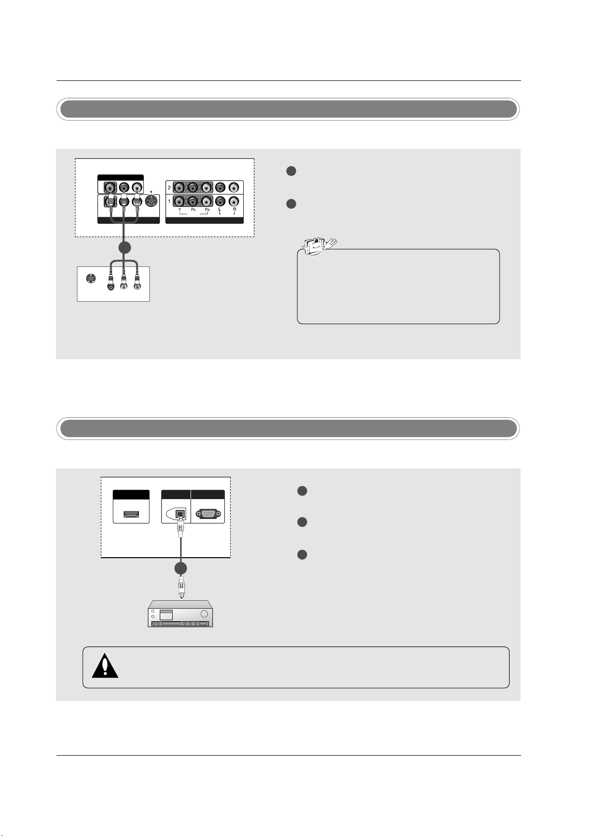
28
Installation
Digital Audio Output
1
2
3
Connect one end of an optical cable to the TV
Digital Audio Optical Output port.
Connect the other end of the optical cable to the
digital audio optical input on the audio equipment.
See the external audio equipment instruction
manual for operation.
When connecting with external audio equipments, such as amplifiers or speakers, please
turn the TV speakers off. (Refer to p.43)
HDMI/DVI IN
DIGITDIGITAL AAL AUDIO UDIO
OUTOUT
OPTICAL
RS-232C INRS-232C IN
(CONTROL & SERVICE)
- Send the TV’s audio to external audio equipment (stereo system) via the Digital Audio Output Optical port.
CAUTION
Do not look into the optical output port. Looking at the laser beam may damage your vision.
1/2
Monitor Out Setup
1
2
Connect the second TV or monitor to the TV’s AV
OUTPUT jacks.
See the Operating Manual of the second TV or
monitor for further details regarding that device’s
input settings.
S-VIDEO
IN
(R) AUDIO (L)
VIDEO
VIDEOVIDEO
AUDIOUDIO
MONO
( )
VIDEOVIDEO
AUDIOUDIO
COMPONENT INCOMPONENT IN
S-VIDEOS-VIDEO
AV IN 1V IN 1
AV OUTV OUT
- The TV has a special signal output capability which allows you to hook up a second TV or monitor.
1/2
• Component 1-2, RGB-PC/RGB-DTV,
HDMI/DVI, DTV input sources cannot be used
for Monitor out.
• We recommend to use the video and audio
output jacks for VCR recording.
Page 78

29
Installation
- This TV provides Plug and Play capability, meaning that the PC adjusts automatically to the TV's settings.
PC Setup
When connecting with a D-sub 15 pin cable
1
2
3
4
Connect the RGB output of the PC to the RGB
(PC/DTV) jack on the set.
Connect the PC audio outputs to the AUDIO
(RGB/DVI) jack on the set.
Turn on the PC and the set.
Select RGB-PC input source with using the
INPUT button on the remote control.
(R) AUDIO (L)
RGB-PC OUTPUT
RGB (PC/DTV)
RGB INRGB IN
AUDIO (RGB/DVI)AUDIO (RGB/DVI)
REMOTEREMOTE
CONTROL INCONTROL IN
(R) AUDIO (L)
RGB-PC OUTPUT
REMOTEREMOTE
CONTROLCONTROL
RGB IN
(PC/DTV)
AUDIO INAUDIO IN
(RGB/DVI)(RGB/DVI)
HDMI/DVI IN
DIGITAL AUDIO
OUT
OPTICAL
RS-232C IN
(CONTROL & SERVICE)
RGB (PC/DTV)
RGB IN
AUDIO (RGB/DVI)
REMOTE
CONTROL IN
SERVICE)
REMOTE
CONTROL
RGB IN
(PC/DTV)
AUDIO IN
(RGB/DVI)
1
2
1
2
PC
When connecting with a HDMI to DVI cable
1
2
3
4
Connect the DVI output of the PC to the HDMI/DVI IN jack on the set.
Connect the audio outputs of the PC to the AUDIO (RGB/DVI) jack on the set.
Turn on the PC and the set.
Select HDMI/DVI input source with using the INPUT button on the remote control.
(R) AUDIO (L)
DVI-PC OUTPUT
HDMI/DHDMI/DVI INVI IN
DIGITDIGITAL AAL AUDIO UDIO
OUTOUT
OPTICAL
RS-232C INRS-232C IN
(CONTR(CONTROLOL & SERSERVICE)VICE)
RGB (PC/DTV)
RGB INRGB IN
AUDIO (RGB/DVI)AUDIO (RGB/DVI)
REMOTEREMOTE
CONTROL INCONTROL IN
(R) AUDIO (L)
DVI-PC OUTPUT
HDMI/DHDMI/DVI INVI IN
DIGITDIGITAL AAL AUDIO UDIO
OUTOUT
OPTICAL
RS-232C INRS-232C IN
(CONTR(CONTROLOL & SERSERVICE)VICE)
REMOTEREMOTE
CONTROLCONTROL
RGB IN
(PC/DTV)
AUDIO INAUDIO IN
(RGB/DVI)(RGB/DVI)
PCPC
• If the PC has a DVI output and no HDMI output, a separated audio connection is necessary.
• If the PC does not support Auto DVI, you need to set the output resolution appropriately. To get the
best picture quality, adjust the output resolution of PC graphics card's output resolution to
1024x768, 60Hz.
1
2
1
2
Page 79

30
Installation
1. To get the best picture quality, adjust the PC
graphics card to 1024x768, 60Hz.
2. Depending on the graphics card, DOS mode may
not work if a HDMI to DVI Cable is in use.
3. When Source Devices connected with HDMI/DVI
Input, output PC Resolution (VGA, SVGA, XGA),
Position and Size may not fit to Screen.Press the
ADJUST button to adjust the screen Position of TV
SET and contact an PC graphics card service center.
4. When Source Devices connected with HDMI/DVI
Input, output TV SET Resolution (480p, 720p,
1080i) and TV SET Display fit EIA/CEA-861-B
Specification to Screen. If not, refer to the Manual
of HDMI/DVI Source Devices or contact your service center.
5. In case HDMI/DVI Source Devices is not connected Cable or poor cable connection, "NO SIGNAL"
OSD display in HDMI/DVI Input. In case that Video
Resolution is not supported TV SET output in
HDMI/DVI Source Devices, "INVALID FORMAT"
OSD display. Refer to the Manual of HDMI/DVI
Source Devices or contact your service center.
6. Check the image on your TV. There may be noise
associated with the resolution, vertical pattern,
contrast or brightness in PC, HDMI/DVI mode. If
noise is present, change the PC or HDMI/DVI
mode to another resolution, change the refresh
rate to another rate or adjust the brightness and
contrast on the menu until the picture is clear. If the
refresh rate of the PC graphic card can not be
changed, change the PC graphic card or consult
the manufacturer of the PC graphic card.
7. Avoid keeping a fixed image on the TV's screen for
a long period of time. The fixed image may become
permanently imprinted on the screen.
8. The synchronization input form for Horizontal and
Vertical frequencies is separate.
Supported Display Resolution
(RGB-PC, HDMI/DVI Mode)
Resolution
* 640x350
* 720x400
640x480
Horizontal
Frequency (kHz)
31.468
31.469
31.469
37.861
37.500
70.08
70.08
59.94
72.80
75.00
Vertical
Frequency (Hz)
Resolution
* RGB-PC only
800x600
1024x768
Horizontal
Frequency (kHz)
35.156
37.879
48.077
46.875
48.363
56.476
60.023
56.25
60.31
72.18
75.00
60.00
70.06
75.02
Vertical
Frequency (Hz)
Page 80

31
Installation
* Adjustment for screen Position, Size, and Phase
* Initializing (Reset to original factory values)
- To initialize the adjusted values
Close
POSITION
GG
SIZE
PHASE
RESET
Adjust
DD
FF
GG
EE
Close
POSITION
SIZE
PHASE
RESET
GG
Adjust
Initialize Settings
Position This function is to adjust
picture to left/right and
up/down as you prefer.
Size This function is to mini-
mize any vertical bars or
stripes visible on the
screen background. And
the horizontal screen size
will also change.
Phase This function allows you to
remove any horizontal
noise and clear or sharpen
the image of characters.
Mini Glossary
- When RGB connect to PC input and select the RGB-PC, this function is used.
- When HDMI/DVI connect to PC input and select HDMI/DVI input, this function is used.
- In RGB-DTV mode, SIZE and PHASE is not available.
- After connecting RGB-PC or HDMI/DVI to PC input and checking the screen quality.
Press the ADJUST button and then use
DD / EE
button to select
POSITION, SIZE, or PHASE.
Press ENTER button and then use
DD / EE
/
FF / GG
buttons to
make appropriate adjustments.
• The PHASE adjustment range is -16 ~ +16.
(In HDMI/DVI-PC mode,
PHASE is not available.)
• The SIZE adjustment range is -30 ~ +30.
Press ENTER button.
1
2
3
Press the ADJUST button and then use
DD / EE
button to select
the RESET option.
Press ENTER button and then use
FF / GG
button to select Yes .
Press ENTER button.
1
2
3
Screen Setup for PC mode
4 5 6
7809
APM
ADJUST
SAP
EZ SOUND
EZ PIC
FREEZE
FLASHBK
ADJUST
4 5 6
7809
APM
ADJUST
SAP
EZ SOUND
EZ PIC
FREEZE
FLASHBK
ADJUST
Page 81

Operation
Operation
Basic operation
Basic operation
1. First, connect power cord correctly. At this moment, the TV switches to standby mode.
In standby mode to turn TV on, press the , INPUT, CH
DD/ EE
button on the TV or press the POWER, TV
INPUT, INPUT, CH
DD/ EE
, Number (0 ~ 9) button on the remote control .
2. Select the viewing source by using TV INPUT, INPUT button on the remote control.
This TV is programmed to remember which power state it was last set to, even if the power cord is out.
3. When finished using the TV, press the POWER button on the remote control. The TV reverts to standby mode.
1. Press the VOL
DD/ EE
button to adjust the volume.
2. If you want to switch the sound off, press the MUTE button.
3. You can cancel this function by pressing the MUTE or VOL
DD/ EE
button.
Press the
CH
DD/ EE
or NUMBER buttons to select a channel number.
- The menus can be shown on the
screen in the selected language.
First select your language.
On Screen Menus Language Selection
Volume Adjustment
Turning on the TV
Channel Selection
Press the MENU button and then use
DD/ EE
button to select the
OPTION menu.
Press the
GG
button and then use
DD/ EE
button to select Language.
Press the
GG
button and then use
DD/ EE
button to select your desired
language. From this point on, the on-screen menus will be shown in the
selected language.
Press EXIT button to return to TV viewing or press MENU button to
return to the previous menu.
1
2
3
4
Previous
MENU
Aspect Ratio
Cinema 3:2 Mode
Caption
Caption/Text
Caption Option
Language
G
ISM Method
Low Power
English
Español (Spanish)
Français (French)
Aspect Ratio
Cinema 3:2 Mode
Caption
Caption/Text
Caption Option
Language
ISM Method
Low Power
• If you intend to be away on vacation, disconnect the power plug from the wall power outlet.
SETUP
VIDEO
AUDIO
TIME
OPTION
G
LOCK
SETUP
VIDEO
AUDIO
TIME
OPTION
LOCK
32
Operation
Page 82

33
Operation
On Screen Menus Selection and
On Screen Menus Selection and
Adjustment
Adjustment
1. Press the MENU button and then DD/ EEbutton to select each menu.
2. Press theGGbutton and then use
DD / EE
/
FF / GG
button to display the available menus.
• Your TV's OSD (On Screen Display) may differ slightly from what is shown in this manual.
How to adjust the OSD screen
SETUP
G
VIDEO
AUDIO
TIME
OPTION
LOCK
EZ Scan
Manual Scan
Channel Edit
DTV Signal
Input Source
Input Label
Set ID
EZ Picture
Contrast 85
Brightness 50
Color 50
Sharpness 50
Tint 0
Color Temperature
Video Reset
R G
Audio Language
EZ SoundRite
EZ Sound
Balance 0
Treble 50
Bass 50
Front Surround
TV Speaker
BBE
L R
Auto Clock
Manual Clock
Off Timer
On Timer
Sleep Timer
Auto Off
Aspect Ratio
Cinema 3:2 Mode
Caption
Caption/Text
Caption Option
Language
ISM Method
Low Power
Lock System
Set Password
Block Channel
Movie Rating
TV Rating-Children
TV Rating-General
Input Block
SETUP
VIDEO
G
AUDIO
TIME
OPTION
LOCK
SETUP
VIDEO
AUDIO
G
TIME
OPTION
LOCK
SETUP
VIDEO
AUDIO
TIME
G
OPTION
LOCK
SETUP
VIDEO
AUDIO
TIME
OPTION
G
LOCK
SETUP
VIDEO
AUDIO
TIME
OPTION
LOCK
G
* Note: These functions are available in
42PC3D/3DV, 50PC3D models only.
Page 83

34
Operation
EZ Scan (Channel Search)
Setup Menu Options
Setup Menu Options
Press the MENU button and then use
DD / EE
button to select the SETUP menu.
Press theGGbutton and then use
DD / EE
button to select EZ Scan.
Press the ENTER button to begin the channel search.
Allow EZ Scan to complete the channel search cycle for ANTENNA, and
CABLE.
1
2
3
Manual Scan
- A password is required to gain
access to Manual Scan menu if
the Lock System is turned on.
Press the MENU button and then use
DD / EE
button to select the SETUP menu.
Press theGGbutton and then use
DD / EE
button to select Manual Scan.
Press the
GG
button and then use
DD / EE
button to select TV, DTV, CATV,
and CADTV.
Press the
GG
button and then use
DD / EE
button to select channel num-
ber you want to add or delete.
Press the ENTER button to add or delete for the channel number.
Press EXIT button to return to TV viewing or press MENU button to
return to the previous menu.
1
2
3
4
5
6
Previous
MENU
EZ Scan
G
Manual Scan
Channel Edit
DTV Signal
Input Source
Input Label
Set ID
Selection (Gor ) leads you
to the EZ scan screen.
ANTENNA
CABLE
Previous
MENU
EZ Scan
Manual Scan
G
Channel Edit
DTV Signal
Input Source
Input Label
Set ID
Select channel type and
RF-channel number.
TV 2
Mini Glossary
TV Analog antenna (over-the-air) TV signal
DTV Digital antenna (over-the-air) TV signal
CATV Analog cable TV signal
CADTV Digital cable TV signal
- Automatically finds all channels
available through antenna or
cable inputs, and stores them in
memory on the channel list.
- Run EZ Scan again after any
Antenna/Cable connection changes.
- A password is required to gain
access to EZ Scan menu if the
Lock System is turned on.
SETUP
G
VIDEO
AUDIO
TIME
OPTION
LOCK
EZ Scan
Manual Scan
Channel Edit
DTV Signal
Input Source
Input Label
Set ID
SETUP
VIDEO
AUDIO
TIME
OPTION
LOCK
SETUP
G
VIDEO
AUDIO
TIME
OPTION
LOCK
EZ Scan
Manual Scan
Channel Edit
DTV Signal
Input Source
Input Label
Set ID
SETUP
VIDEO
AUDIO
TIME
OPTION
LOCK
Page 84

35
Operation
- There are two different ways in
order to add or delete scanned
channels. One is "Custom List"
and the other is "Favorite List" in
the channel list. Both of them are
available after EZ Scan on the
SETUP menu.
- A Custom List can be created by
toggling each channel on or off
with ENTER button. The channels in the Custom List are displayed in black color, and the
channels deleted from the
Custom List are displayed in
gray color. Once a channel is
highlighted you can add or
delete the channel by referring to
the small window at the top-left
corner of the screen.You can
create your own Favorite List.
Use the FAV button on the
remote control when a channel is
highlighted and then you can
add or delete the channel to/from
the Favorite List.
Channel Edit
Press the MENU button and then use
DD / EE
button to select the SETUP menu.
Press theGGbutton and then use
DD / EE
button to select Channel Edit.
Press the
GG
button. You will now see a screen filled with channel num-
bers and a preview picture.
Use
DD / EE
/
FF / GG
button to select a channel and then use the ENTER
button to add or delete it. Press FAV button to add the channel to the
Favorite List. The heart-mark will appear in front of that channel number.
Press EXIT button to return to TV viewing or press MENU button to
return to the previous menu.
1
2
3
4
5
Previous
MENU
EZ Scan
Manual Scan
Channel Edit
G
DTV Signal
Input Source
Input Label
Set ID
Selection ( Gor ) leads you
to the channel edit screen.
SETUP
G
VIDEO
AUDIO
TIME
OPTION
LOCK
EZ Scan
Manual Scan
Channel Edit
DTV Signal
Input Source
Input Label
Set ID
SETUP
VIDEO
AUDIO
TIME
OPTION
LOCK
* Custom List
Page 85

36
Operation
DTV Signal Strength
- Shows how strong your DTV signal is and whether you need to
adjust your antenna or digital
cable input. The higher the signal strength, the less likely you
are to experience picture degradation.
- DTV Signals: Only when the
input signal is DTV or CADTV,
this function is available.
Press the MENU button and then use
DD / EE
button to select the SETUP menu.
Press theGGbutton and then use
DD / EE
button to select DTV Signal.
View the on-screen signal strength monitor to see the quality of the signal
being received.
Press EXIT button to return to TV viewing or press MENU button to
return to the previous menu.
1
2
3
4
Previous
MENU
EZ Scan
Manual Scan
Channel Edit
DTV Signal
G
Input Source
Input Label
Set ID
Bad Normal Good
SETUP
G
VIDEO
AUDIO
TIME
OPTION
LOCK
EZ Scan
Manual Scan
Channel Edit
DTV Signal
Input Source
Input Label
Set ID
SETUP
VIDEO
AUDIO
TIME
OPTION
LOCK
- Changes the picture source so
you can watch your TV, cable TV,
VCR, DVD, or any other devices
that are connected to your TV.
Input Source
Press the MENU button and then use
DD / EE
button to select the SETUP menu.
Press theGGbutton and then use
DD / EE
button to select Input Source.
Press the
GG
button and then use
DD / EE
button to select the source:
Antenna, Cable, AV1, AV2, Component1, Component2, RGB-DTV (or
RGB-PC), or HDMI/DVI.
• To toggle RGB-DTV and RGB-PC, select RGB-DTV(or RGB-PC) and
press GGbutton.
Press EXIT button to return to TV viewing or press MENU button to
return to the previous menu.
1
2
3
4
Previous
MENU
EZ Scan
Manual Scan
Channel Edit
DTV Signal
Input Source
G
Input Label
Set ID
Antenna
Cable
AV1
AV2
Component1
Component2
RGB-PC
HDMI/DVI
SETUP
G
VIDEO
AUDIO
TIME
OPTION
LOCK
EZ Scan
Manual Scan
Channel Edit
DTV Signal
Input Source
Input Label
Set ID
SETUP
VIDEO
AUDIO
TIME
OPTION
LOCK
Setup Menu Options continued
Setup Menu Options continued
Page 86

37
Operation
- Sets a label to each input source
or lets you skip the input source
which is not in use when you
press INPUT button.
Input Label
Press the MENU button and then use
DD / EE
button to select the SETUP menu.
Press theGGbutton and then use
DD / EE
button to select Input Label.
Press the
GG
button and then use
DD / EE
button to select the source: AV1-
2, Component1-2, RGB or HDMI/DVI.
Press the
FF / GG
button to select the label.
Press EXIT button to return to TV viewing or press MENU button to
return to the previous menu.
1
2
3
4
5
Previous
MENU
EZ Scan
Manual Scan
Channel Edit
DTV Signal
Input Source
Input Label
G
Set ID
AV1 Cable Box
AV2 VCR
Component1 DVD
Component2 Set Top Box
RGB PC
HDMI/DVI Game
SETUP
G
VIDEO
AUDIO
TIME
OPTION
LOCK
EZ Scan
Manual Scan
Channel Edit
DTV Signal
Input Source
Input Label
Set ID
SETUP
VIDEO
AUDIO
TIME
OPTION
LOCK
Page 87

38
Operation
APM (Adaptive Picture Mode)
- It allows a viewer to select their
preferred mode after comparing
picture (Daylight, Normal, Night
Time and Custom) settings.
- Note: While operating the 4-split,
any button except APM, ENTER,
EXIT,
DD / EE
/
FF / GG
, VOLUME
DD
/
EE
, MUTE button on the remote
control are not available.
VVideo Menu Options
ideo Menu Options
EZ Picture
- EZ Picture adjusts the TV for the best
picture appearance. Select the preset
value in the EZ Picture menu based on
the program category.
- When adjusting Video menu options (contrast, brightness, color, sharpness, tint,
and color temperature) manually, EZ
Picture automatically changes to Custom.
-
Daylight, Normal, Night Time,
Movie, Video Game, and Sports set-
tings are preset for optimum picture quality at the factory and are not adjustable.
Press the EZ PIC button repeatedly to select the picture appear-
ance setup option as shown below:
Custom (your own settings),
Daylight, Normal, Night Time, Movie, Video Game, and
Sports.
• You can also adjust
EZ Picture in the VIDEO menu.
Press the EXIT button to save and return to TV viewing.
1
2
Press the APM button. The screen is divided to 4-split.
Press the
DD / EE
/
FF / GG
button to navigate 4 EZ Pictures. By pressing
the ENTER button, you can select the desired mode.
Press the EXIT button to save and return to TV viewing.
1
2
Night Time
Navigate Select Exit
Custom
Daylight Normal
FF GG
GG
FF
EXIT
EZ PIC
4 5 6
7809
APM
ADJUST
SAP
EZ SOUND
EZ PIC
FREEZE
FLASHBK
APM
1 2 3
4 5 6
7809
EZ SOUND
EZ PIC
APM
ADJUST
FLASHBK
SAP
FREEZE
Page 88

39
Operation
Color Temperature Control
Previous
MENU
EZ Picture
Contrast
Brightness
Color
Sharpness
Tint
Color Temperature
G
Video Reset
Cool
Medium
Warm
Previous
MENU
EZ Picture
Contrast
Brightness
Color
Sharpness
Tint
Color Temperature
Video Reset
G
Selection ( Gor ) resets to
the factory settings (default).
EZ Picture
Contrast 85
Brightness 50
Color 50
Sharpness 50
Tint 0
Color Temperature
Video Reset
R G
- Choose one of three automatic
color adjustments. Set to warm
to enhance hotter colors such as
red, or set to cool to see less
intense colors with more blue.
- Use to quickly reset all the Video
menu options to their original
factory preset values.
Press the MENU button and then use
DD / EE
button to select the VIDEO menu.
Press the
GG
button and then use
DD / EE
button to select Video Reset.
Press the
GG
button to reset the Video menu options to original values.
1
2
3
Press the MENU button and then use
DD / EE
button to select the VIDEO menu.
Press the
GG
button and then use
DD / EE
button to select the desired pic-
ture option (
Contrast, Brightness, Color, Sharpness, or Tint).
Press the
GG
button and then use
FF / GG
button to make appropriate adjustments.
Press EXIT button to return to TV viewing or press MENU button to
return to the previous menu.
1
2
3
4
Manual Picture Control (EZ Picture-Custom option)
- Adjust the picture appearance to
suit your preference and viewing situations.
Previous
MENU
EZ Picture
Contrast 85
G
Brightness 50
Color 50
Sharpness 50
Tint 0
Color Temperature
Video Reset
R G
Contrast 90
FF
G
EE
Video Reset
Press the MENU button and then use
DD / EE
button to select the VIDEO menu.
Press the
GG
button and then use
DD / EE
button to select Color Temperature.
Press the
GG
button and then use
DD / EE
button to select either Cool,
Medium, or Warm.
Press EXIT button to return to TV viewing or press MENU button to
return to the previous menu.
1
2
3
4
SETUP
VIDEO
G
AUDIO
TIME
OPTION
LOCK
SETUP
VIDEO
G
AUDIO
TIME
OPTION
LOCK
EZ Picture
Contrast 85
Brightness 50
Color 50
Sharpness 50
Tint 0
Color Temperature
Video Reset
R G
SETUP
VIDEO
G
AUDIO
TIME
OPTION
LOCK
SETUP
VIDEO
AUDIO
TIME
OPTION
LOCK
SETUP
VIDEO
AUDIO
TIME
OPTION
LOCK
SETUP
VIDEO
AUDIO
TIME
OPTION
LOCK
Page 89

40
Operation
Audio Menu Options
Audio Menu Options
- Other languages may be available
if a digital signal is provided by the
broadcasting station.
- Scans for changes in sound
level during commercials, then
adjusts the sound to match the
specified audio level. EZ
SoundRite makes sure that the
volume level remains consistent
whether you are watching a
commercial or a regular TV program.
Audio Language
EZ SoundRite
Previous
MENU
Audio Language
G
EZ SoundRite
EZ Sound
Balance
Treble
Bass
Front Surround
TV Speaker
BBE
English
Spanish
French
Previous
MENU
Audio Language
EZ SoundRite
G
EZ Sound
Balance
Treble
Bass
Front Surround
TV Speaker
BBE
Off
On
Press the MENU button and then use
DD / EE
button to select the
AUDIO menu.
Press the
GG
button and then use
DD / EE
button to select Audio Language.
Press the GGbutton and then use
DD / EE
button to select: English,
Spanish, or French.
Press EXIT button to return to TV viewing or press MENU button to
return to the previous menu.
1
2
3
4
Press the MENU button and then use
DD / EE
button to select the
AUDIO menu.
Press the
GG
button and then use
DD / EE
button to select EZ SoundRite.
Press the GGbutton and then use
DD / EE
button to select Off or On.
Press EXIT button to return to TV viewing or press MENU button to
return to the previous menu.
1
2
3
4
Audio Language
EZ SoundRite
EZ Sound
Balance 0
Treble 50
Bass 50
Front Surround
TV Speaker
BBE
L R
Audio Language
EZ SoundRite
EZ Sound
Balance 0
Treble 50
Bass 50
Front Surround
TV Speaker
BBE
L R
SETUP
VIDEO
AUDIO
G
TIME
OPTION
LOCK
SETUP
VIDEO
AUDIO
G
TIME
OPTION
LOCK
SETUP
VIDEO
AUDIO
TIME
OPTION
LOCK
SETUP
VIDEO
AUDIO
TIME
OPTION
LOCK
Page 90

41
Operation
EZ Sound
Manual Sound Control (EZ Sound-Custom option)
- EZ Sound lets you enjoy the best
sound without any special
adjustment because the TV sets
the appropriate sound options
based on the program content.
- When adjusting sound options
(treble, bass, and front surround)
manually, EZ Sound automatically switches
Custom.
-
Normal, Stadium, News, Music,
and
Theater are preset for
good sound quality at the factory
and are not adjustable.
- Adjust the sound to suit your
taste and room situations.
Press the EZ SOUND button repeatedly to select the appropriate sound
setup as shown below:
Custom (your own settings), Normal,
Stadium, News, Music, and Theater.
• You can also adjust
EZ Sound in the AUDIO menu.
Press EXIT button to save and return to TV viewing.
1
2
Press the MENU button and then use
DD / EE
button to select the
AUDIO menu.
Press the
GG
button and then use
DD / EE
button to select the desired
sound option (
Balance, Treble, or Bass).
Press the
GG
button and then use
FF / GG
button to make appropriate
adjustments.
Press EXIT button to return to TV viewing or press MENU button to
return to the previous menu.
1
2
3
4
Previous
MENU
Audio Language
EZ SoundRite
EZ Sound
Balance 0
G
Treble 80
Bass 80
Front Surround
TV Speaker
BBE
L R
EE
Balance 0
FF
G
L R
SETUP
VIDEO
AUDIO
G
TIME
OPTION
LOCK
SETUP
VIDEO
AUDIO
TIME
OPTION
LOCK
1 2 3
4 5 6
7809
APM
ADJUST
SAP
EZ SOUND
EZ PIC
FREEZE
FLASHBK
EZ SOUND
Page 91

42
Operation
Audio Menu Options continued
Audio Menu Options continued
- is a trademark of SRS
Labs, Inc.
- TruSurround XT technology is
incorporated under license from
SRS Labs, Inc.
- Manufactured under license from
Dolby Laboratories. “Dolby” and
the double-D symbol are trademarks of Dolby Laboratories.
Stereo/SAP Broadcasts Setup
Front Surround
Press the MENU button and then use
DD / EE
button to select the
AUDIO menu.
Press the
GG
button and then use
DD / EE
button to select Front
Surround
.
Press the
GG
button and then use
DD / EE
button to select Off, 3D
EchoSound System or SRS (Sound Retrieval System) TruSurround XT.
Press EXIT button to return to TV viewing or press MENU button to
return to the previous menu.
1
2
3
4
Previous
MENU
Audio Language
EZ SoundRite
EZ Sound
Balance
Treble
Bass
Front Surround
G
TV Speaker
BBE
Off
3D EchoSound System
SRS TruSurround XT
Audio Language
EZ SoundRite
EZ Sound
Balance 0
Treble 50
Bass 50
Front Surround
TV Speaker
BBE
L R
Use the SAP button to select your desired MTS mode in analog signal.
Each time you press the SAP button,
Mono, Stereo, or SAP appear in
turn.
• If other languages available on the digital signal, select them with the
SAP button.
Press EXIT button to save and return to TV viewing.
1
2
Mini Glossary
SRS TruSurround XT
Takes advantage of any multi-channel format without needing to add extra speakers or equipment. Dialog clarity, bass enrichment,
and the addition of stereo audio enhancement that produces an immersive sound experience from standard stereo material.
3D EchoSound System
Creates a stunning simulated stereo effects from any mono sound and a realistic three-dimensional sound with a very wide and
deep sound stage from stereo sound.
- This TV can receive MTS stereo programs and any SAP (Secondary Audio
Program) that accompanies the stereo
program; if the station transmits an
additional sound signal as well as the
original one.
- When having selected Stereo or SAP
button on the remote control, this TV
can only receive the signal in case that
the TV station transmits the proper signals.
- Mono sound is automatically received
if the broadcast is only in Mono; even
though Stereo or SAP has been
selected.
- Select Mono if you want to listen to the
mono sound in remote fringe areas
during stereo/SAP broadcasting.
- Stereo or SAP can be received in
Analog channel.
SETUP
VIDEO
AUDIO
G
TIME
OPTION
LOCK
SETUP
VIDEO
AUDIO
TIME
OPTION
LOCK
1 2 3
4 5 6
7809
APM
ADJUST
SAP
EZ SOUND
EZ PIC
FREEZE
FLASHBK
SAP
Page 92

43
Operation
- BBE High Definition Sound
restores clarity and presence for
better speech intelligibility and
music realism.
TV Speakers On/Off Setup
- Turn TV speakers off if using
external audio equipment.
Feature turns the TV Speakers
option On or Off.
BBE
Press the MENU button and then use
DD / EE
button to select the
AUDIO menu.
Press the
GG
button and then use
DD / EE
button to select BBE.
Press the GGbutton and then use
DD / EE
button to select Off or On.
Press EXIT button to return to TV viewing or press MENU button to
return to the previous menu.
1
2
3
4
Previous
MENU
Audio Language
EZ SoundRite
EZ Sound
Balance
Treble
Bass
Front Surround
TV Speaker
G
BBE
Off
On
Press the MENU button and then use
DD / EE
button to select the
AUDIO menu.
Press the
GG
button and then use
DD / EE
button to select TV Speaker.
Press the GGbutton and then use
DD / EE
button to select Off or On.
Press EXIT button to return to TV viewing or press MENU button to
return to the previous menu.
1
2
3
4
Previous
MENU
Audio Language
EZ SoundRite
EZ Sound
Balance
Treble
Bass
Front Surround
TV Speaker
BBE
G
Off
On
Audio Language
EZ SoundRite
EZ Sound
Balance 0
Treble 50
Bass 50
Front Surround
TV Speaker
BBE
L R
Audio Language
EZ SoundRite
EZ Sound
Balance 0
Treble 50
Bass 50
Front Surround
TV Speaker
BBE
L R
• Manufactured under license from BBE Sound, Inc.
SETUP
VIDEO
AUDIO
G
TIME
OPTION
LOCK
SETUP
VIDEO
AUDIO
G
TIME
OPTION
LOCK
SETUP
VIDEO
AUDIO
TIME
OPTION
LOCK
SETUP
VIDEO
AUDIO
TIME
OPTION
LOCK
Page 93

44
Operation
TTime Menu Options
ime Menu Options
- If current time setting is wrong,
reset the clock manually.
Auto Clock Setup
Manual Clock Setup
Press the MENU button and then use
DD / EE
button to select the TIME menu.
Press the
GG
button and then use
DD / EE
button to select Auto Clock.
Press the GGbutton and then use
DD / EE
button to select On.
Press the GGbutton and then use
DD / EE
button to select your viewing
area time zone.
• U.S.A:
Eastern, Central, Mountain, Pacific, Alaska, or Hawaii.
• Canada:
Eastern, Central, Mountain, Pacific, Nfld, or Atlantic.
Press the
GG
button and then use
DD / EE
button to select Auto, Off, On,
depending on whether or not your viewing area observes Daylight
Saving time.
Press EXIT button to return to TV viewing or press MENU button to
return to the previous menu.
1
2
3
4
5
6
Press the MENU button and then use
DD / EE
button to select the TIME menu.
Press the
GG
button and then use
DD / EE
button to select Manual
Clock
.
Press the
GG
button and then use
FF / GG
button to select either the year,
date, or time option. Once selected, use the
DD / EE
button to set the year,
date, and time options.
Press EXIT button to return to TV viewing or press MENU button to
return to the previous menu.
1
2
3
4
Previous
MENU
Auto Clock
G
Manual Clock
Off Timer
On Timer
Sleep Timer
Auto Off
Off
On
Time Zone Eastern
Auto
Daylight
Saving
Auto Clock
Manual Clock
Off Timer
On Timer
Sleep Timer
Auto Off
Previous
MENU
Auto Clock
Manual Clock
G
Off Timer
On Timer
Sleep Timer
Auto Off
Year - - - Date - - / - Time - - : - - - -
Auto Clock
Manual Clock
Off Timer
On Timer
Sleep Timer
Auto Off
- The time is set automatically
from a digital channel signal.
- The digital channel signal
includes information for the current time provided by the broadcasting station.
- Set the clock manually, if the current time is set incorrectly by the
auto clock function.
SETUP
VIDEO
AUDIO
TIME
G
OPTION
LOCK
SETUP
VIDEO
AUDIO
TIME
OPTION
LOCK
SETUP
VIDEO
AUDIO
TIME
G
OPTION
LOCK
SETUP
VIDEO
AUDIO
TIME
OPTION
LOCK
Page 94

45
Operation
On/Off Timer Setup
Sleep Timer
- Timer function operates only if
current time has been set.
- Off-Timer function overrides OnTimer function if they are set
both set to the same time.
- The TV must be in standby mode
for the On-Timer to work.
- If you do not press any button
within 2 hours after the TV turns
on with the On Timer function,
the TV will automatically revert to
standby mode.
- The Sleep Timer turns the TV off
at the preset time. Note that this
setting is cleared when the TV is
turned off.
- You can also set up the
Sleep
Timer
in the TIME menu.
Press the MENU button and then use
DD / EE
button to select the TIME menu.
Press the GGbutton and then use
DD / EE
button to select Off Timer or
On Timer.
Press the GGbutton and then use
DD / EE
button to select On.
• To cancel
On/Off Timer function, select Off.
Press the
GG
button and then use
DD / EE
button to set the hour.
Press the
GG
button and then use
DD / EE
button to set the minutes.
For only
On Timer function
Press the
GG
button and then use
DD / EE
button to select the channel at
turn-on.
Press the
GG
button and then use
DD / EE
button to set the sound level at
turn-on.
Press EXIT button to return to TV viewing or press MENU button to
return to the previous menu.
1
2
3
4
5
6
7
Previous
MENU
Auto Clock
Manual Clock
Off Timer
On Timer
G
Sleep Timer
Auto Off
Off
On
Time 6 : 30 AM
Ch. TV 2-0
Vol 17
Press the TIMER button repeatedly to select the number of minutes.
First the
Off option appears on the screen, followed by the following
sleep timer options: 10, 20, 30, 60, 90, 120, 180, and 240 minutes.
When the number of minutes you want is displayed on the screen,
press the TIMER button. The timer begins to count down from the number of minutes selected.
To check the remaining minutes before the TV turns off, press the
TIMER button once.
To cancel the Sleep Timer, press the TIMER button repeatedly to select
Off.
1
2
3
4
Auto Clock
Manual Clock
Off Timer
On Timer
Sleep Timer
Auto Off
SETUP
VIDEO
AUDIO
TIME
G
OPTION
LOCK
SETUP
VIDEO
AUDIO
TIME
OPTION
LOCK
MENU
DAY
-
GUIDE
DAY+
RATIO
ENTER
PAG E
EXIT
TIMER
CC
INFO
TIMER
Page 95

46
Operation
TTime Menu Options continued
ime Menu Options continued
Auto Off
- If set to on and there is no input
signal, the TV turns off automatically after 10 minutes.
Press the MENU button and then use
DD / EE
button to select the TIME menu.
Press the
GG
button and then use
DD / EE
button to select Auto Off.
Press the GGbutton and then use
DD / EE
button to select Off or On.
Press EXIT button to return to TV viewing or press MENU button to
return to the previous menu.
1
2
3
4
Previous
MENU
Auto Clock
Manual Clock
Off Timer
On Timer
Sleep Timer
Auto Off
G
Off
On
If set to On and there is no
input signal, the TV turns off
automatically after 10
minutes.
Auto Clock
Manual Clock
Off Timer
On Timer
Sleep Timer
Auto Off
SETUP
VIDEO
AUDIO
TIME
G
OPTION
LOCK
SETUP
VIDEO
AUDIO
TIME
OPTION
LOCK
Page 96

47
Operation
Aspect Ratio Control
Option Menu Features
Option Menu Features
- Lets you choose the way an analog picture with a 4:3 aspect ratio
is displayed on your TV with a
16:9 ratio picture format. When
you receive an analog picture
with a 4:3 aspect ratio on your
16:9 TV, you need to specify how
the picture is to be displayed.
- If you are viewing a picture with
a 16:9 aspect ratio, you can’t use
the Horizon aspect ratio option.
- Horizon aspect ratio is not available for Component 1-2
(720p/1080i) / RGB-DTV
(720p/1080i)/HDMI/DVI-DTV
(720p/1080i) /DTV(720p/1080i)
input source.
- In RGB-PC/DVI-PC input source,
only either 4:3 or 16:9 aspect
ratio is available.
- If a fixed image is displayed on
the screen for a long time, the
image may become imprinted
on the screen and remain visible.
Press the RATIO button repeatedly to select the desired picture format.
• You can also adjust
Aspect Ratio in the OPTION menu.
•
Set By Program
Selects the proper picture proportion to match the source’s image.
(4:3
→→
4:3, 16:9
→→
16:9)
•
4:3
Choose 4:3 when you want to view a picture with an original 4:3
aspect ratio, with gray bars appearing at both the left and right sides.
•
16:9
Choose 16:9 when you want to adjust the picture horizontally, in a linear proportion to fill the entire screen.
•
Horizon
Choose Horizon when you want to adjust the picture in a non-linear
proportion, that is, more enlarged at both sides, to create a panorama
view.
•
Zoom 1
Choose Zoom 1 when you want to view the picture without any alteration. However, the top and bottom portions of the picture will be
cropped.
•
Zoom 2
Choose Zoom 2 when you want the picture to be altered, both horizontally extended and vertically cropped. The picture taking a halfway
trade off between alteration and screen coverage.
•
Cinema Zoom
Choose Cinema Zoom when you want to enlarge the picture in correct proportion. Note: When enlarging or reducing the picture, the
image may become distorted.
You can adjust the enlarge proportion of Cinema Zoom using
DD / EE
button. The adjustment range is 1~16.
1
POWER
MENU
DAY
-
GUIDE
DAY+
RATIO
VCR
TV
DVD
ENTER
EXIT
TIMER
CC
INFO
AUDIO
CABLE
STB
MODE
TV INPUT
INPUT
RATIO
Page 97

48
Operation
Caption
Press the MENU button and then use
DD / EE
button to select the
OPTION menu.
Press the
GG
button and then use
DD / EE
button to select Caption.
Press the GGbutton and then use
DD / EE
button to select Off or On.
Press EXIT button to return to TV viewing or press MENU button to
return to the previous menu.
1
2
3
4
Previous
MENU
Aspect Ratio
Cinema 3:2 Mode
Caption
G
Caption/Text
Caption Option
Language
ISM Method
Low Power
Off
On
Aspect Ratio
Cinema 3:2 Mode
Caption
Caption/Text
Caption Option
Language
ISM Method
Low Power
Cinema 3:2 Mode Setup
- Most movies are 24 frames/sec,
but TV signal is 30 frames/sec.
- This option lets the TV do 3:2
pull-down operation for you to
watch movies at the best motion
appearance.
- This feature operates only in
AV1, AV2, Component 480i
mode.
Press the MENU button and then use
DD / EE
button to select the
OPTION menu.
Press the
GG
button and then use
DD / EE
button to select Cinema 3:2 Mode.
Press the GGbutton and then use
DD / EE
button to select Off or On.
Press EXIT button to return to TV viewing or press MENU button to
return to the previous menu.
1
2
3
4
Previous
MENU
Aspect Ratio
Cinema 3:2 Mode
G
Caption
Caption/Text
Caption Option
Language
ISM Method
Low Power
Off
On
Aspect Ratio
Cinema 3:2 Mode
Caption
Caption/Text
Caption Option
Language
ISM Method
Low Power
SETUP
VIDEO
AUDIO
TIME
OPTION
G
LOCK
SETUP
VIDEO
AUDIO
TIME
OPTION
LOCK
SETUP
VIDEO
AUDIO
TIME
OPTION
G
LOCK
SETUP
VIDEO
AUDIO
TIME
OPTION
LOCK
Option Menu Features continued
Option Menu Features continued
Page 98

49
Operation
- Select a caption mode for displaying captioning information if
provided on a program.
- Analog caption displays information at any position on the screen.
- Text displays information, usually at the bottom position and is
used for a data service.
- Caption/Text, if provided by the
broadcaster, would be available
for both digital and analog channels on the Antenna/Cable.
- This TV is programmed to
remember the caption/text mode
it was last set to, when you turn
the power off.
Caption/Text
* Digital Broadcasting System Captions
* Analog Broadcasting System Captions
- Choose the language you want
the DTV/CADTV Captions to
appear in.
- Other languages can be chosen
for digital sources only if they are
included on the program.
Previous
MENU
Aspect Ratio
Cinema 3:2 Mode
Caption
Caption/Text
G
Caption Option
Language
ISM Method
Low Power
CC 1
CC 2
CC 3
CC 4
Text 1
Text 2
Text 3
Text 4
Press the MENU button and then use
DD / EE
button to select the
OPTION menu.
Press the
GG
button and then use
DD / EE
button to select Caption/Text.
Press the
GG
button and then use
DD / EE
button to select available cap-
tion languages:
English, Spanish, or French.
Press EXIT button to return to TV viewing or press MENU button to
return to the previous menu.
1
2
3
4
Previous
MENU
Aspect Ratio
Cinema 3:2 Mode
Caption
Caption/Text
G
Caption Option
Language
ISM Method
Low Power
English
Spanish
French
Aspect Ratio
Cinema 3:2 Mode
Caption
Caption/Text
Caption Option
Language
ISM Method
Low Power
Aspect Ratio
Cinema 3:2 Mode
Caption
Caption/Text
Caption Option
Language
ISM Method
Low Power
Press the MENU button and then use
DD / EE
button to select the
OPTION menu.
Press the
GG
button and then use
DD / EE
button to select Caption/Text.
Press the
GG
button and then use
DD / EE
button to select caption: CC1,
CC2, CC3, CC4, Text1, Text2, Text3, or Text4.
•
CAPTION
The term for the words that scroll across the bottom of the TV screen;
usually the audio portion of the program provided for the hearing
impaired.
• TEXT
The term for the words that appear in a large black frame and almost
cover the entire screen; usually messages provided by the broadcaster.
Press EXIT button to return to TV viewing or press MENU button to
return to the previous menu.
1
2
3
4
Use the CC button repeatedly to select Caption Off, CC1, CC2, CC3,
CC4, Text1, Text2, Text3, or Text4.
Press EXIT button to save and return to TV viewing.
1
2
SETUP
VIDEO
AUDIO
TIME
OPTION
G
LOCK
SETUP
VIDEO
AUDIO
TIME
OPTION
LOCK
SETUP
VIDEO
AUDIO
TIME
OPTION
G
LOCK
SETUP
VIDEO
AUDIO
TIME
OPTION
LOCK
Page 99

50
Operation
- Customize the DTV/CADTV captions that appear on your screen.
Caption Option
Press the MENU button and then use
DD / EE
button to select the
OPTION menu.
Press the
GG
button and then use
DD / EE
button to select Caption Option.
Press the
GG
button and then use
FF / GG
button to select Custom.
Use
DD / EE
button to customize the Style, Font, etc., to your preference.
A preview icon is provided at the bottom of the screen, use it to see the
caption language.
• Size: Set the size the words will appear in.
•
Font: Select a typeface for the words.
•
Text Color: Choose a color for the text.
•
Text Opacity: Specify the opacity for the text color.
•
Bg (Background) Color: Select a background color.
•
Bg (Background) Opacity: Select the opacity for the background color.
•
Edge Type: Select an edge type.
•
Edge Color: Select a color for the edges.
Press EXIT button to return to TV viewing or press MENU button to
return to the previous menu.
1
2
3
4
5
Previous
MENU
Aspect Ratio
Cinema 3:2 Mode
Caption
Caption/Text
Caption Option
G
Language
ISM Method
Low Power
Style Custom
Size A Standard
Font Font 0
Text Color White
Text Opacity
Solid
Bg Color Black
Bg Opacity Solid
Edge Type None
Edge Color Black
Aspect Ratio
Cinema 3:2 Mode
Caption
Caption/Text
Caption Option
Language
ISM Method
Low Power
SETUP
VIDEO
AUDIO
TIME
OPTION
G
LOCK
SETUP
VIDEO
AUDIO
TIME
OPTION
LOCK
- Low power reduces the power
consumption of plasma display.
Low Power (42PC3D/3DV, 50PC3D only)
Press the MENU button and then use
DD / EE
button to select the
OPTION menu.
Press the
GG
button and then use
DD / EE
button to select Low Power.
Press the
GG
button and then use
DD / EE
button On or Off.
Press EXIT button to return to TV viewing or press MENU button to
return to the previous menu.
1
2
3
4
Previous
MENU
Aspect Ratio
Cinema 3:2 Mode
Caption
Caption/Text
Caption Option
Language
ISM Method
Low Power
G
Off
On
Aspect Ratio
Cinema 3:2 Mode
Caption
Caption/Text
Caption Option
Language
ISM Method
Low Power
SETUP
VIDEO
AUDIO
TIME
OPTION
G
LOCK
SETUP
VIDEO
AUDIO
TIME
OPTION
LOCK
Option Menu Features continued
Option Menu Features continued
Page 100

51
Operation
- A frozen still picture from a
PC/video game displayed on the
screen for prolonged periods will
result in a ghost image ; even
though the image is changed.
Use our unique method to minimize any fixed image on the
screen.
ISM (Image Sticking Minimization) Method (42PC3D/3DV, 50PC3D only)
Press the MENU button and then use
DD / EE
button to select the
OPTION menu.
Press the
GG
button and then use
DD / EE
button to select ISM Method.
Press the GGbutton and then use
DD / EE
button to select Normal,
White Wash, Orbiter or Inversion.
• Normal
If image sticking is never a problem, ISM is not necessary - set to
Normal.
• White Wash
White Wash removes permanent images from the screen.
Note: An excessive permanent image may be impossible to clear
entirely with White Wash. To return to normal viewing, press the any
button.
• Orbiter
Orbiter may help prevent ghost images. However, it is best not to
allow any fixed image to remain on the screen. To avoid a permanent
image on the screen, the image will move once per 2 minutes: Left
→→
Right
→→
Upside →→Downside →→Right →→Left →→Downside →→Upside.
•
Inversion
Inversion will automatically invert the plasma display panel color every
30 minutes.
Press EXIT button to return to TV viewing or press MENU button to
return to the previous menu.
1
2
3
4
Previous
MENU
Aspect Ratio
Cinema 3:2 Mode
Caption
Caption/Text
Caption Option
Language
ISM Method
G
Low Power
Normal
White Wash
Orbiter
Inversion
Aspect Ratio
Cinema 3:2 Mode
Caption
Caption/Text
Caption Option
Language
ISM Method
Low Power
SETUP
VIDEO
AUDIO
TIME
OPTION
G
LOCK
SETUP
VIDEO
AUDIO
TIME
OPTION
LOCK
 Loading...