

LG PA11K, 42PT250, 42PT250-TA, 60PZ850-TA Service Manual

PLASMA TV
SERVICE MANUAL
CAUTION
BEFORE SERVICING THE CHASSIS,
READ THE SAFETY PRECAUTIONS IN THIS MANUAL.
CHASSIS : PA11K
MODEL : 42PT250 42PT250-TA
North/Latin America http://aic.lgservice.com
Europe/Africa http://eic.lgservice.com
Asia/Oceania http://biz.lgservice.com
Internal Use Only
Printed in Korea
P/NO : MFL67121901 (1102-REV00)

- 2 -
LGE Internal Use OnlyCopyright ©2011 LG Electronics Inc. All rights reserved.
Only for training and service purposes
CONTENTS
CONTENTS ............................................................................................................................... 2
SAFETY PRECAUTIONS ...........................................................................................................3
SPECIFICATION.........................................................................................................................4
ADJUSTMENT INSTRUCTION ..................................................................................................6
BLOCK DIAGRAM ...................................................................................................................14
EXPLODED VIEW ..................................................................................................................15
CIRCUIT DIAGRAM .....................................................................................................................
- 3 -
LGE Internal Use OnlyCopyright ©2011 LG Electronics Inc. All rights reserved.
Only for training and service purposes
SAFETY PRECAUTIONS
Many electrical and mechanical parts in this chassis have special safety-related characteristics. These parts are identified by in
the Schematic Diagram and Exploded View.
It is essential that these special safety parts should be replaced with the same components as recommended in this manual to
prevent X-RADIATION, Shock, Fire, or other Hazards.
Do not modify the original design without permission of manufacturer.
General Guidance
An isolation Transformer should always be used during the
servicing of a receiver whose chassis is not isolated from the AC
power line. Use a transformer of adequate power rating as this
protects the technician from accidents resulting in personal injury
from electrical shocks.
It will also protect the receiver and it's components from being
damaged by accidental shorts of the circuitry that may be
inadvertently introduced during the service operation.
If any fuse (or Fusible Resistor) in this monitor is blown, replace it
with the specified.
When replacing a high wattage resistor (Oxide Metal Film
Resistor, over 1W), keep the resistor 10mm away from PCB.
Keep wires away from high voltage or high temperature parts.
Due to high vacuum and large surface area of picture tube,
extreme care should be used in handling the Picture Tube.
Do not lift the Picture tube by it's Neck.
Leakage Current Cold Check(Antenna Cold Check)
With the instrument AC plug removed from AC source, connect
an electrical jumper across the two AC plug prongs. Place the
AC switch in the on position, connect one lead of ohm-meter to
the AC plug prongs tied together and touch other ohm-meter
lead in turn to each exposed metallic parts such as antenna
terminals, phone jacks, etc.
If the exposed metallic part has a return path to the chassis, the
measured resistance should be between 1MΩ and 5.2MΩ.
When the exposed metal has no return path to the chassis the
reading must be infinite.
An other abnormality exists that must be corrected before the
receiver is returned to the customer.
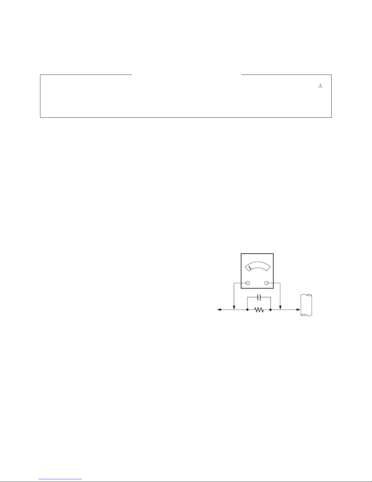
Leakage Current Hot Check (See below Figure)
Plug the AC cord directly into the AC outlet.
Do not use a line Isolation Transformer during this check.
Connect 1.5K/10watt resistor in parallel with a 0.15uF capacitor
between a known good earth ground (Water Pipe, Conduit, etc.)
and the exposed metallic parts.
Measure the AC voltage across the resistor using AC voltmeter
with 1000 ohms/volt or more sensitivity.
Reverse plug the AC cord into the AC outlet and repeat AC
voltage measurements for each exposed metallic part. Any
voltage measured must not exceed 0.75 volt RMS which is
corresponds to 0.5mA.
In case any measurement is out of the limits specified, there is
possibility of shock hazard and the set must be checked and
repaired before it is returned to the customer.
Leakage Current Hot Check circuit
1.5 Kohm/10W
To Instrument's
exposed
METALLIC PARTS
Good Earth Ground
such as WATER PIPE,
CONDUIT etc.
AC Volt-meter
IMPORTANT SAFETY NOTICE
0.15uF
- 4 -
LGE Internal Use OnlyCopyright ©2011 LG Electronics Inc. All rights reserved.
Only for training and service purposes
SPECIFICATION
NOTE : Specifications and others are subject to change without notice for improvement
.
V Application Range
This spec is applied to PDP TV used PA11K Chassis.
V Specification
Each part is tested as below without special appointment.
(1) Temperature : 25 °C ± 5 °C (77 °F ± 9 °F), CST : 40 ± 5
(2) Relative Humidity: 65 % ± 10 %
(3) Power Voltage: Standard Input voltage (100 V - 240 V ~, 50 / 60 Hz)
* Standard Voltage of each product is marked by models.
(4) Specification and performance of each parts are followed each drawing and specification by part number in accordance with
SBOM.
(5) The receiver must be operated for about 20 minutes prior to the adjustment.
V Test Method
(1) Performance : LGE TV test method followed.
(2) Demanded other specification
Safety : CE, IEC specification, EMC : CE, IEC
V Module Specification
(1) 2D - 42” HD
No Item Specification Remark
1 Display Screen Device 106 cm (42 inch) wide Color Display Module PDP
2 Aspect Ratio 16:9
3 PDP Module PDP42T3####,
RGB Closed (Well) Type, Glass Filter (38%)
Pixel Format: 1024 horiz. By 768 ver
4 Operating Environment 1) Temp. : 0 deg ~ 40 deg
2) Humidity : 20 % ~ 80 %
5 Storage Environment 3) Temp. : -20 deg ~ 60 deg
LGE SPEC
4) Humidity : 10 % ~ 90 %
6 Input Voltage AC 100 V ~ 240 V, 50 / 60 Hz Maker LG
Model Name
42PT250-TA
Brand
LG
Market
Australia, New Zealand, Malaysia, Indonesia, Singapore
South Africa, Israel, Iran, Vietnam, Kenya, Non-EU analog
Model Name
42PT250-TA
Brand
Safety : IEC/EN60065
EMI : CISPR13
Market
Australia, New Zealand, Malaysia, Indonesia, Singapore
South Africa, Israel, Iran, Vietnam, Kenya, Non-EU analog
- 5 -
LGE Internal Use OnlyCopyright ©2011 LG Electronics Inc. All rights reserved.
Only for training and service purposes
V Model General Specification
No Item Specification Remarks
1 Market Albania, Austria, Belgium, Bosnia, Bulgaria, Coratia, 36 Country
Czech, Denmark, Estonia, Finland, France, Germany,
Greece, Hungary, Ireland, Italy, Kazakhstan, Latvia,
Lithuania, Luxembourg, Morocco, Netherlands, Norway,
Poland, Portugal, Romania, Russia, Serbia, Slovenia,
Spain, Sweden, Slovakia, Switzerland, Turkey, Ukraine,
UK
2 Broadcasting system 1) PAL/SECAM BG EU (PAL Market)
2) PAL/SECAM DK
3) PAL Ⅰ/Ⅱ
4) SECAM L/L’
5) DVB T
6) DVB C
3 Receiving system Analog : Upper Heterodyne
Digital : COFDM
4 Scart Jack (1EA) PAL, SECAM
5 Video Input (1EA) PAL, SECAM, NTSC Side AV
6 Component Input (1EA) Y/Cb/Cr, Y/ Pb/Pr
7 RGB Input RGB-PC Analog (D-Sub 15Pin)
8 HDMI Input (4EA) HDMI-PC HDMI/DVI,HDMI2, HDMI3
HDMI-DTV
9 Audio Input (3 EA) RGB/DVI Audio, Component, AV L/R Input
10 SPDIF Out(1 EA) SPDIF Out
11 USB(1EA) For SVC, S/W Download, DivX
12 LAN For UK models

- 6 -
LGE Internal Use OnlyCopyright ©2011 LG Electronics Inc. All rights reserved.
Only for training and service purposes
ADJUSTMENT INSTRUCTION
1. Application Range
This spec sheet is applied to all of the PDP TV with PA11K
chassis.
2. Specification
(1) The adjustment is according to the order which is
designated and which must be followed, according to the
plan which can be changed only on agreeing.
(2) Power adjustment : Free Voltage. (100 V ~ 240 V, 50 Hz /
60 Hz.)
(3) Magnetic Field Condition: Nil.
(4) Input signal Unit: Product Specification Standard.
(5) Reserve after operation: Above 5 Minutes (Heat Run)
Temperature : at 25 °C ± 5 °C
Relative humidity 65 % ± 10 %
Input voltage : 220 V, 60 Hz.
(6) Adjustment equipments : Color Analyzer (CA-210 or CA-
110), DDC Adjustment Jig equipment, SVC remote
controller.
(7) The receiver must be operated for about 5 minutes prior to
the adjustment when module is in the circumstance of over
15 °C
- In case of keeping module is in the circumstance of 0 °C,
it should be placed in the circumstance of above 15 °C
for 2 hours
- In case of keeping module is in the circumstance of below
-20 °C, it should be placed in the circumstance of above
15 °C for 3 hours,.
O After RGB Full White in HEAT-RUN Mode, the receiver
must be operated prior to the adjustment.
O Enter into HEAT-RUN MODE
1) Press the POWER ON KEY on R/C for adjustment.
2) OSD display and screen display PATTERN MODE.
- Set is activated HEAT run without signal generator in this
mode.
- Single color pattern ( WHITE ) of HEAT RUN MODE uses
to check panel.
- Caution : If you turn on a still screen more than 20
minutes (Especially digital pattern, cross hatch pattern),
an after image may be occur in the black level part of the
screen.
(8) Push The “IN STOP KEY” - For memory initialiLAtion.
Case1 : Software version up
1) After downloading S/W by USB , TV set will reboot
automatically
2) Push “In-stop” key
3) Push “Power on” key
4) Function inspection
5) After function inspection, Push “In-stop” key.
Case2 : Function check at the assembly line
1) When TV set is entering on the assembly line, Push
“In-stop” key at first.
2) Push “Power on” key for turning it on.
-> If you push “Power on” key, TV set will recover
channel information by itself.
3) After function inspection, Push “In-stop” key.
3.
Main PCB check process
* APC - After Manual-Insert, executing APC
3-1. Boot file Download
(1) Execute ISP program “Mstar ISP Utility” and then click
“Config” tab.
(2) Set as below, and then click “Auto Detect” and check “OK”
message
If “Error” is displayed, Check connection between computer,
jig, and set.
(3) Click “Read” tab, and then load download file (XXXX.bin)
by clicking “Read”
(4) Click “Connect” tab. If “Can’t” is displayed, Check
connection between computer, jig, and set.
(5) Click “Auto” tab and set as below.
(6) Click “Run”.
(7) After downloadng, check “OK” message.
- 7 -
LGE Internal Use OnlyCopyright ©2011 LG Electronics Inc. All rights reserved.
Only for training and service purposes
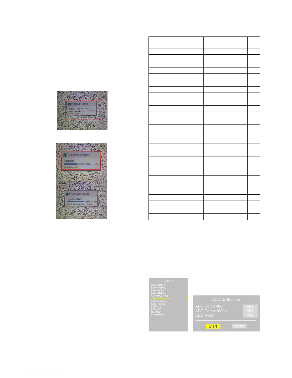
4. USB DOWNLOAD
(*.epk file download)
(1) Put the USB Stick to the USB socket
(2) Automatically detecting update file in USB Stick
- If your downloaded program version in USB Stick is Low,
it didn’t work.
But your downloaded version is High, USB data is
automatically detecting
(3) Show the message “Copying files from memory”
(4) Updating is staring.
(5) Updating Completed, The TV will restart automatically.
(6) If your TV is turned on, check your updated version and
Tool option. (explain the Tool option, next stage)
* If downloading version is more high than your TV have,
TV can lost all channel data. In this case, you have to
channel recover. if all channel data is cleared, you didn’t
have a DTV/ATV test on production line.
* After downloading, have to adjust TOOL OPTION again.
(1) Push "IN-START" key in service remote controller.
(2) Select "Tool Option 1" and Push “OK” button.
(3) Punch in the number. (Each of models has their number.)
(4) Completed selecting Tool option.
5. ADC Process
5-1. ADC
- Enter Service Mode by pushing “ADJ”key,
- Enter Internal ADC mode by pushing “
G” key at “5. ADC
Calibration”
* Caution: Using ‘power on’ button of the Adjustment R/C , power
on TV.
Model Module Tool Tool Tool Tool Tool
option1 option2 option3 option4 option5
50PZ550-ZA 50R3 36928 37966 54144 26956 32
60PZ550-ZA 60R3 49216 37966 54144 26956 32
60PZ250-ZA 60R3 49280 37966 54144 26892 32
50PZ250-ZA 50R3 36992 37966 54144 26892 32
50PW450-ZA 50T3 37056 37966 54144 26892 32
42PW450-ZA 42T3 24768 37966 54144 26892 32
50PV350-ZA 50R3 37216 21582 54144 26892 32
50PT350-ZA 50T3 37312 21582 54144 26892 32
42PT350-ZA 42T3 25024 21582 54144 26892 32
60PV250-ZA 60R3 49536 21582 54144 26892 32
42PT250-ZA 42T3 25088 21582 54144 26892 32
60PV250-TA 60R3 49536 22934 54144 26892 32
50PV250-TA 50R3 37248 22934 54144 26892 32
50PW350-TA 50T3 37088 39318 54144 26956 32
42PW350-TA 42T3 24800 39318 54144 26956 32
60PZ550-TA 50R3 49216 39318 54144 26956 32
50PZ550-TA 50R3 36928 39318 54144 26956 32
50PT250-TA 50T3 37376 22934 54144 26892 32
42PT250-TA 42T3 25088 22934 54144 26892 32
50PZ550T-ZA 50R3 36928 37966 54144 29001 544
50PZ550T-ZA 50R3 36928 37966 54144 29004 544
60PZ250T-TA 60R3 49280 37966 54144 28940 544
50PZ250T-ZA 50R3 36992 37966 54144 28940 544
50PW450T-ZA 50T3 37056 37966 54144 28940 544
42PW450T-ZA 42T3 24768 37966 54144 28940 544
50PV350T-ZA 50R3 37216 21582 54144 28940 544
60PV250T-ZA 60R3 49536 21582 54144 28940 544
- 8 -
LGE Internal Use OnlyCopyright ©2011 LG Electronics Inc. All rights reserved.
Only for training and service purposes
* ADC Calibration Protocol (RS232)
Adjust Sequence
- aa 00 00 [Enter Adjust Mode]
- xb 00 40 [Component1 Input (480i)]
- ad 00 10 [Adjust 480i Comp1]
- xb 00 60 [RGB Input (1024*768)]
- ad 00 10 [Adjust 1024*768 RGB]
- aa 00 90 End Adjust mode
* Required equipment : Adjustment R/C.
6. Function Check
6-1. Check display and sound
- Check Input and Signal items. (cf. work instructions)
(1) TV
(2) AV (SCART1/SCART2/ CVBS)
(3) COMPONENT (480i)
(4) RGB (PC : 1024 x 768 @ 60hz)
(5) HDMI
(6) PC Audio In
* Display and Sound check is executed by Remote
controller.
* Caution : Not to push the INSTOP KEY after completion if the
function inspection.
7. Total Assembly line process
7-1. POWER PCB Assy voltage adjustment
(Vs voltage adjustment)
O Required Equipment for adjustment
- D.M.M
O Condition for adjustment
- No signal with the snow noise in RF mode)
7-2. Adjustment Preparation
- Required Equipment
O Remote controller for adjustment
O Color Analyzer ( CS-1000, CA-100,100+,CA-210 or same
product : CH 10 (PDP)
* Please adjust CA-210, CA-100+ by CS-1000 before
measuring
O Auto W/B adjustment instrument(only for Auto adjustment)
O 9 Pin D-Sub Jack(RS232C) is connected to the AUTO W/B
EQUIPMENT.
Before Adjust of White Balance, Please press POWER ONLY
key
Adjust Process will start by execute RS232C Command.
O Color temperature standards according to CSM and Module
O CS-1000/CA-100+/CA-210(CH 10)
White balance adjustment coordinates and color temperature.
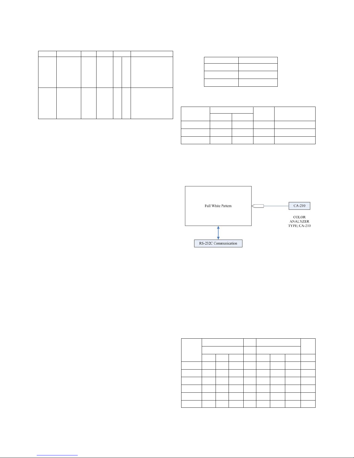
* Connecting picture of the measuring instrument (On
Automatic control)
- Inside PATTERN is used when W/B is controlled. Connect
to auto controller or push Adjustment R/C POWER-ON
->Enter the mode of White-Balance, the pattern will come
out.
* Auto-control interface and directions
(1) Adjust in the place where the influx of light like floodlight
around is blocked. (Illumination is less than 10ux).
(2) Measure and adjust after sticking the Color Analyzer (CA-
100+, CA210 ) to the side of the module.
(3) Aging time
After aging start, keep the Power on (no suspension of
power supply) and heat-run over 5 minutes
O Auto adjustment Map(RS-232C)
RS-232C COMMAND
[ CMD ID DATA ]
Wb 00 00 White Balance Start
Wb 00 ff White Balance End
CSM PLASMA
Cool 11000K
Medium 9300K
Warm 6500K
CSM
Color Coordinate
Temp ±Color Coordinate
xy
Cool 0.276 0.283 11000K 0.002
Medium 0.285 0.293 9300K 0.002
Warm 0.313 0.329 6500K 0.002
RS-232C COMMAND
CENTER
[CMD ID DATA] MIN (DEFAULT) MAX
Cool Mid Warm Cool Mid Warm
R Gain jg Ja jd 00 192 192 192 192
G Gain jh Jb je 00 192 192 192 192
B Gain ji Jc jf 00 192 192 192 192
R Cut 64 64 64 128
G Cut 64 64 64 128
B Cut 64 64 64 128
NO Item CMD 1 CMD 2 Data 0
Enter Adjust A A 0 0 When transfer the
Adjust ‘Mode In’‘Mode In’
Mode Carry the
command.
ADC ADC A D 1 0 Automatically
adjust Adjust adjustment
(The use of
a internal pattern)
- 9 -
LGE Internal Use OnlyCopyright ©2011 LG Electronics Inc. All rights reserved.
Only for training and service purposes
* Caution
- Color Temperature : COOL, Medium, Warm.
- One of R Gain/G Gain/ B Gain should be kept on 0xC0, and
adjust other two lower than C0.
(when R/G/B Gain are all C0, it is the FULL Dynamic Range
of Module)
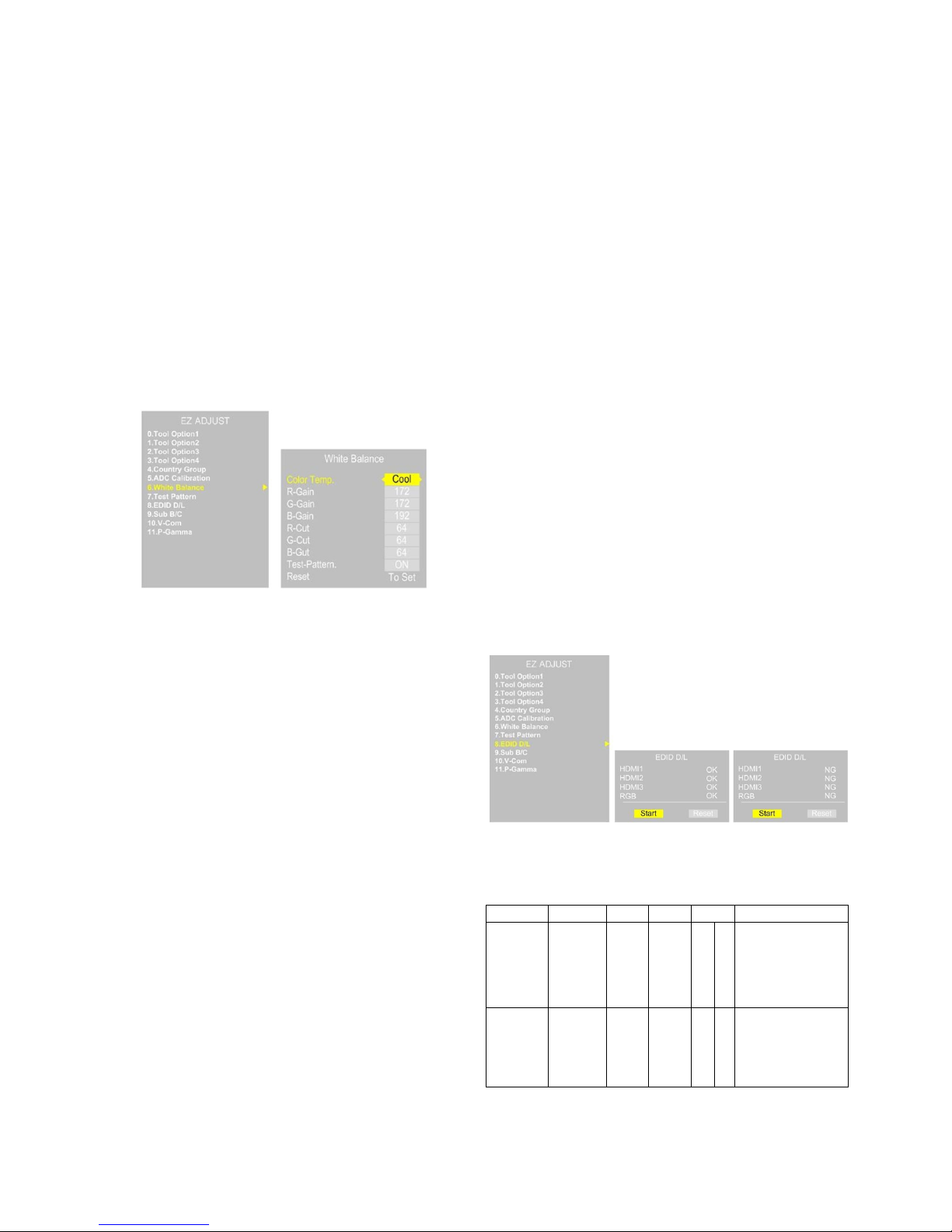
* Manual W/B process using adjusts Remote control.
(1) After enter Service Mode by pushing “ADJ” key,
(2) Enter White Balance by pushing “
G” key at “. White
Balance”
(3) Stick the sensor to the center of the screen and select
each items(Red/Green/Blue Gain) using
D/E (CH +/-) key
on R/C.
(4) Adjust R/G/B Gain using
F/G (VOL +/-) key on R/C.
(5) Adjust three modes all(Cool/Medium/Warm) : Fix the one
of R/G/B Gain and Change the others.
(6) When the adjustment is completed, Enter “COPY ALL”.
(7) Exit adjustment mode using EXIT key on R/C.
* After You finish all adjustments, Press °∞In-start°± button
and compare Tool option and Area option value with its
BOM, if it is correctly same then unplug the AC cable.
If it is not same, then correct it same with BOM and unplug
AC cable.
For correct it to the model’s module from factory JIG model.
* Push The “N STOP KEY” after completing the function
inspection. And Mechanical Power Switch must be set “ON”.
* To check the coordinates of White Balance, you have to
measure at the below conditions.
Picture mode : Vivid, Energy Saving : Off, Below the
Advanced control, Dynamic Contrast : Off, Dynamic Colour :
Off
Colour Temp.
-> Picture Mode change : Vivid ? Vivid(User)
7-3. DPM operation confirmation
(Only Apply for MNT Model)
* Check if Power LED Color and Power Consumption operate
as standard.
(1) Set Input to RGB and connect D-sub cable to set
(2) Measurement Condition: (100~240V@ 50/60Hz)
(3) Confirm DPM operation at the state of screen without
Signal
7-4. DDC EDID Write (RGB 128Byte )
-> Not used any more, Use Auto D/L
(1) Connect D-sub Signal Cable to D-Sub Jack.
(2) Write EDID DATA to EEPROM (24C02) by using DDC2B
protocol.
(3) Check whether written EDID data is correct or not.
* For SVC main Ass’y, EDID have to be downloaded to
Insert Process in advance.
7-5 DDC EDID Write (HDMI 256Byte)
-> Not used any more, Use Auto D/L
(1) Connect HDMI Signal Cable to HDMI Jack.
(2) Write EDID DATA to EEPROM(24C02) by using DDC2B
protocol.
(3) Check whether written EDID data is correct or not.
* For SVC main Ass’y, EDID have to be downloaded to
Insert Process in advance.
7-6. EDID DATA
(1) All Data : HEXA Value
(2) Changeable Data :
*: Serial No : Controlled / Data:01
**: Month : Controlled / Data:00
***:Year : Controlled
****:Check sum
7-7. EDID DATA Auto Download
(1) Press Adj. key on the Adj. R/C,
(2) Select EDID D/L menu.
(3) By pressing Enter key, EDID download will begin
(4) If Download is successful, OK is display, but If Download is
failure, NG is displayed.
(5) If Download is failure, Re-try downloads.
*Caution: Never connect HDMI & D-sub Cable when EDID
downloaded.
O Edid data and Model option download (RS232)
NO Item CMD 1 CMD 2 Data 0
Enter download A A 0 0 When transfer the
download ‘Mode In’‘Mode In’
Mode Carry the
command.
EDID data download A E 00 10 Automatically
Model download
option (The use of
download a internal pattern)
- 10 -
LGE Internal Use OnlyCopyright ©2011 LG Electronics Inc. All rights reserved.
Only for training and service purposes
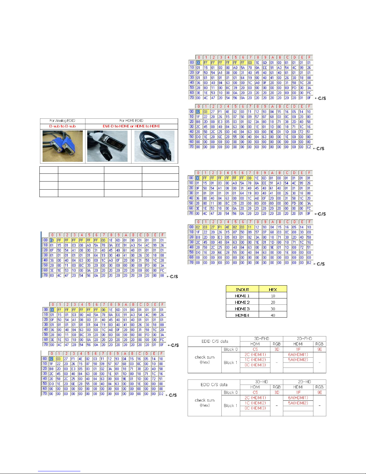
7-8. Manual Download
* Caution
* Use the proper signal cable for EDID Download
- Analog EDID : Pin3 exists
- Digital EDID : Pin3 exists
* Caution:
- Never connect HDMI & D-sub Cable at the same time.
- Use the proper cables below for EDID Writing.
- Download HDMI1, HDMI2 separately because HDMI1 is
different from HDMI2.
7-9. EDID DATA
(1) 2D - HD RGB EDID data
(2) 2D - HD HDMI1 EDID data
(3) 2D - HD HDMI2 EDID data
(4) 2D - HD HDMI3 EDID data
ⓐ Vender ID
O Checksum: Changeable by total EDID data.
No. Item Condition Hex Data
1 Manufacturer ID GSM 1E6D
2 Version Digital : 1 01
3 Revision Digital : 3 03
- 11 -
LGE Internal Use OnlyCopyright ©2011 LG Electronics Inc. All rights reserved.
Only for training and service purposes
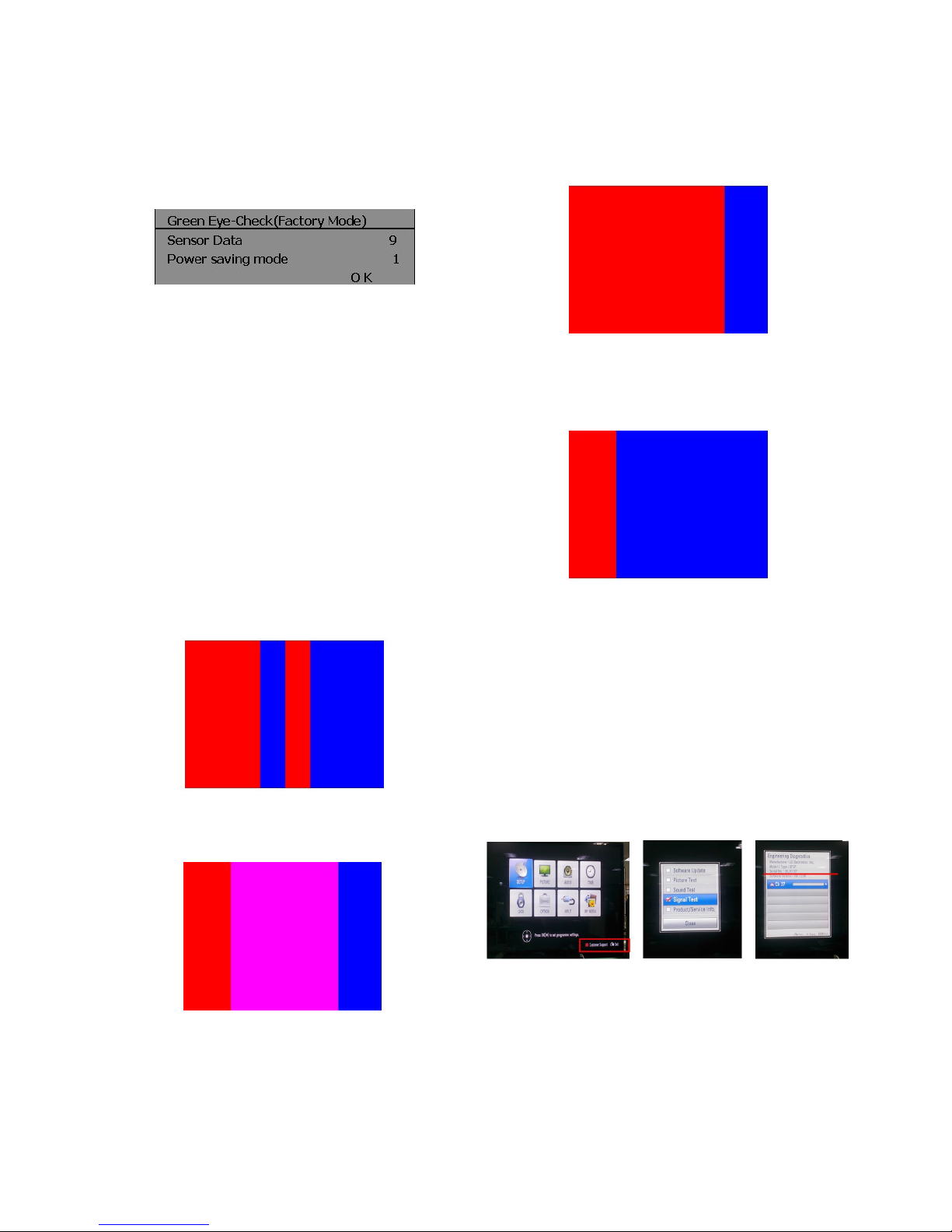
8. Checking the EYE-Q Operation.
(1) Press the EYE Key on the adjustment remote controller.
(2) Check the Sensor DATA ( It must be under 10) and keep
the data longer than 1.5s
(3) Check ‘OK’
(Sensor DATA 0 ~ 4095, Power Saving Mode 0 ~ 12)
* IF you press IN-STAP Button, change Green Eye-check OSD.
9. Ping TEST
(DVB T2 model only, PP11B/L)
* This test is to check Network operation.
(1) Connect LAN cable from Computer to TV Set
(2) When network operates normally, you can see “OK” on
Computer
10. 3D Function Test
(Pattern Generator MSPG-3233, HDMI mode NO. 371 ,
pattern No. 81)
(1) Please input 3D test pattern like below
(2) Enter 3D mode , then select side by side
(If you don’t wear a 3D Glasses, you will see the picture
like below)
(3) Put on the 3D Glasses, And block the right side of Glasses
(LEFT:OPEN[TEST], RIGHT:CLOSED)
And check the middle sides of picture , RED -> normal ,
others -> abnormal
(4) Put on the 3D Glasses, And block the right side of Glasses
(LEFT:CLOSED, RIGHT:OPEN[TEST])
And check the middle sides of picture , BLUE -> normal ,
others -> abnormal
11. Model name & Serial number
download
11-1. Model name & Serial number D/L
(1) Press “Power on” key of service remocon.(Baud rate :
115200 bps)
(2) Connect RS232 Signal Cable to RS-232 Jack.
(3) Write Serial number by use RS-232.
(4) Must check the serial number at signal test of customer
support. (Refer to below).
 Loading...