

LG OM7550D Service Manual
SERVICE MANUAL
SERVICE MANUAL
CAUTION
BEFORE SERVICING THE UNIT, READ THE “SAFETY PRECAUTIONS”
IN THIS MANUAL.
Internal Use Only
Website http://biz.lgservice.com
SPEAKER SYSTEM
JULY, 2015P/NO : AFN77277031
MODEL: OM7550D
MODEL: OM7550D

CONTENTS
SECTION 1 ........ SUMMARY
SECTION 2 ........ CABINET & MAIN CHASSIS
SECTION 3 ........ ELECTRICAL
SECTION 4 ........ REPLACEMENT PARTS LIST
1-1

SECTION 1
SUMMARY
CONTENTS
SERVICING PRECAUTIONS ............................................................................................................................ 1-3
ESD PRECAUTIONS ......................................................................................................................................... 1-5
HIDDEN KEY MODE ......................................................................................................................................... 1-6
FIRMWARE UPGRADE GUIDE ........................................................................................................................ 1-8
SPECIFICATIONS ........................................................................................................................................... 1-10
1-2
SERVICING PRECAUTIONS
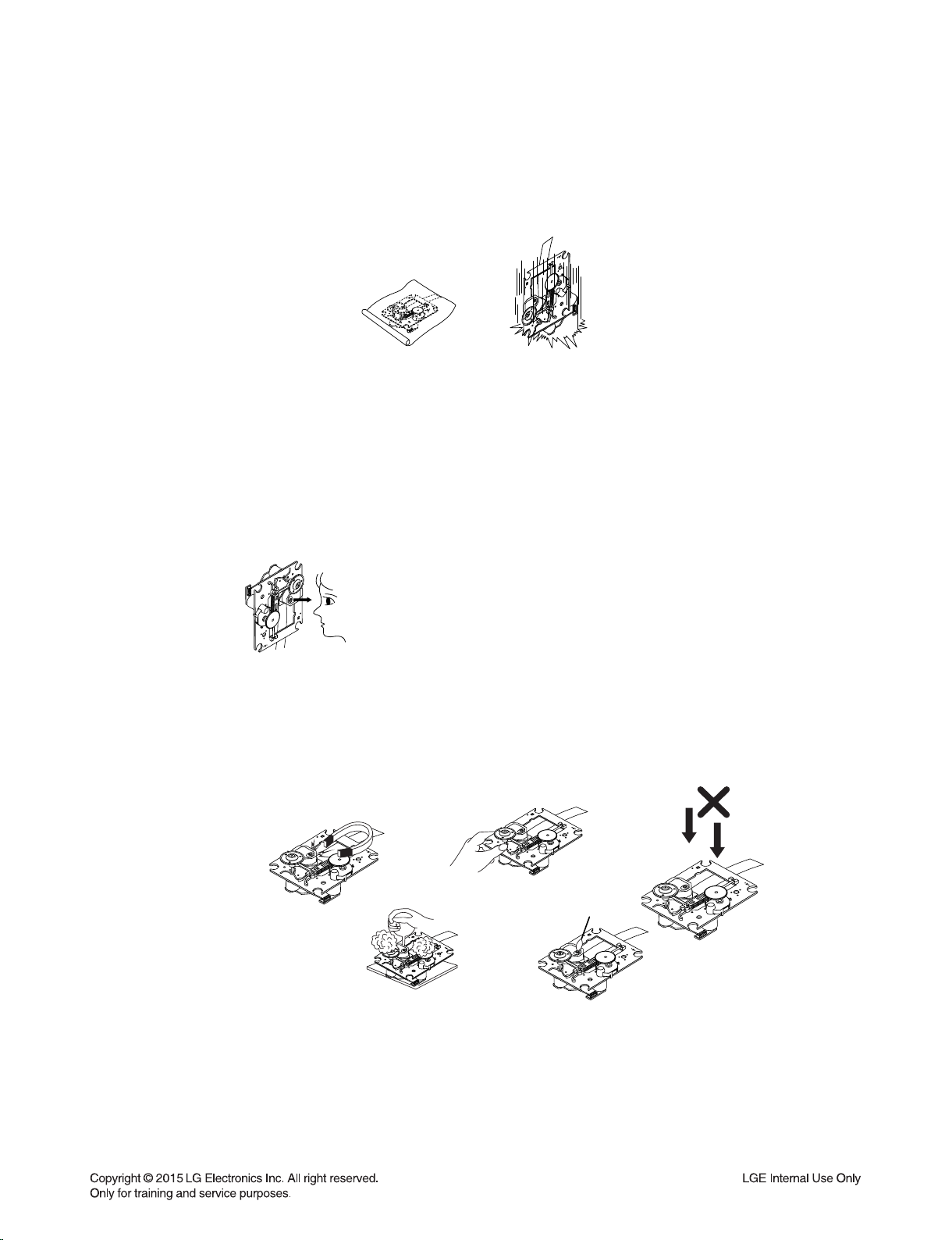
NOTES REGARDING HANDLING OF THE PICK-UP
1. Notes for transport and storage
1) The pick-up should always be left in its conductive bag until immediately prior to use.
2) The pick-up should never be subjected to external pressure or impact.
Storage in conductive bag
Drop impact
2. Repair notes
1) The pick-up incorporates a strong magnet, and so should never be brought close to magnetic materials.
2) The pick-up should always be handled correctly and carefully, taking care to avoid external pressure and
impact. If it is subjected to strong pressure or impact, the result may be an operational malfunction and/or
damage to the printed-circuit board.
3) Each and every pick-up is already individually adjusted to a high degree of precision, and for that reason
the adjustment point and installation screws should absolutely never be touched.
4) Laser beams may damage the eyes!
Absolutely never permit laser beams to enter the eyes!
Also NEVER switch ON the power to the laser output part (lens, etc.) of the pick-up if it is damaged.
NEVER look directly at the laser beam, and don’t allow
contact with fingers or other exposed skin.
5) Cleaning the lens surface
If there is dust on the lens surface, the dust should be cleaned away by using an air bush (such as used
for camera lens). The lens is held by a delicate spring. When cleaning the lens surface, therefore, a cotton swab should be used, taking care not to distort lens.
Pressure
Magnet
How to hold the pick-up
Cotton swab
Conductive Sheet
6) Never attempt to disassemble the pick-up.
Spring has excess pressure. If the lens is extremely dirty, apply isopropyl alcohol to the cotton swab.
(Do not use any other liquid cleaners, because they will damage the lens.) Take care not to use too much
of this alcohol on the swab, and do not allow the alcohol to get inside the pick-up.
1-3
Pressure
NOTES REGARDING COMPACT DISC PLAYER REPAIRS
1. Preparations
1) Compact disc players incorporate a great many ICs as well as the pick-up (laser diode). These components
are sensitive to, and easily affected by, static electricity. If such static electricity is high voltage, components
can be damaged, and for that reason components should be handled with care.
2) The pick-up is composed of many optical components and other high-precision components. Care must be
taken, therefore, to avoid repair or storage where the temperature or humidity is high, where strong magnetism is present, or where there is excessive dust.
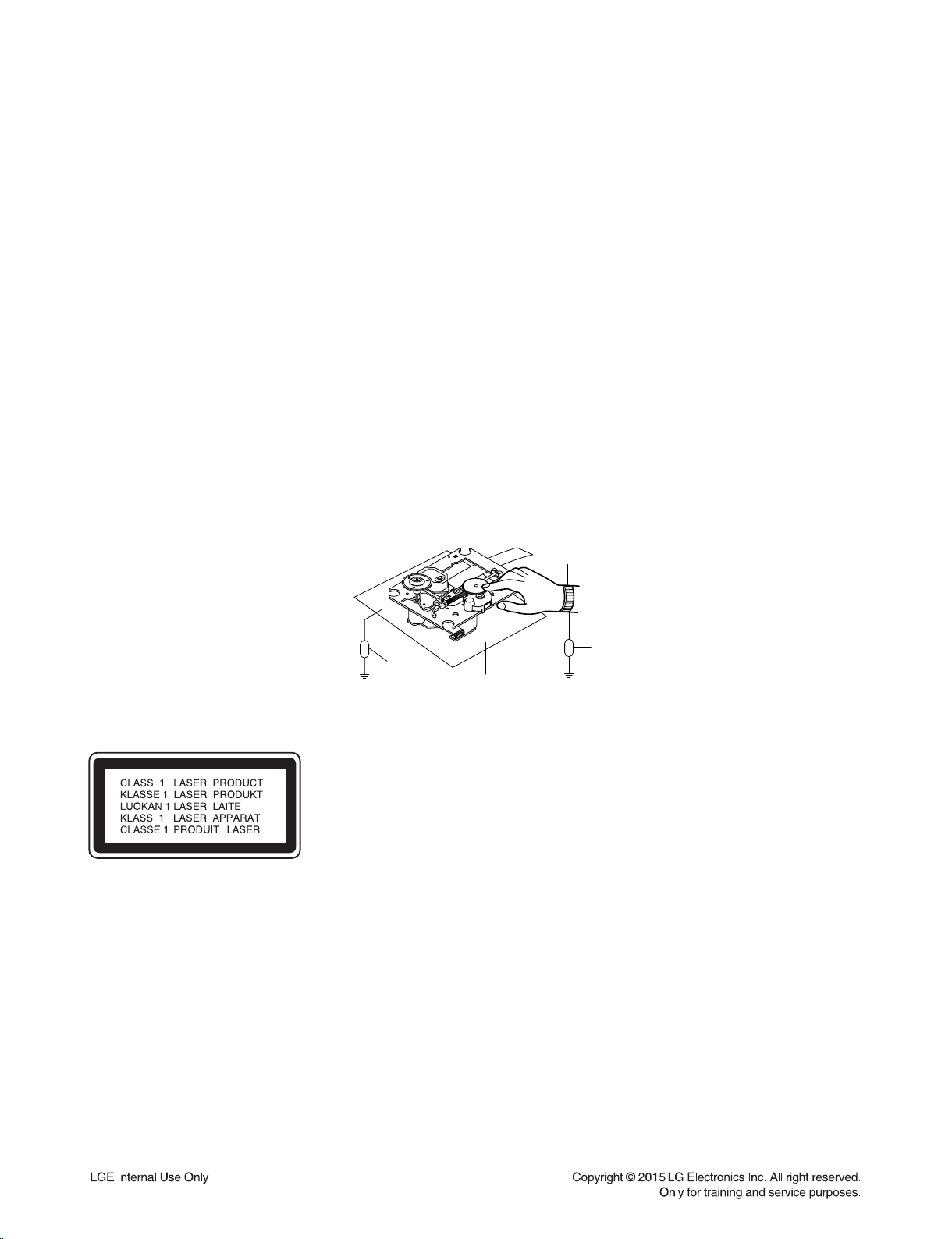
2. Notes for repair
1) Before replacing a component part, first disconnect the power supply lead wire from the unit
2) All equipment, measuring instruments and tools must be grounded.
3) The workbench should be covered with a conductive sheet and grounded.
When removing the laser pick-up from its conductive bag, do not place the pick-up on the bag. (This is
because there is the possibility of damage by static electricity.)
4) To prevent AC leakage, the metal part of the soldering iron should be grounded.
5) Workers should be grounded by an armband (1 M)
6) Care should be taken not to permit the laser pick-up to come in contact with clothing, in order to prevent
static electricity changes in the clothing to escape from the armband.
7) The laser beam from the pick-up should NEVER be directly facing the eyes or bare skin.
Armband
Resistor
(1 M)
Resistor
(1 M)
CAUTION: CLASS 1M VISIBLE AND INVISIBLE LASER RADIATION WHEN
OPEN. DO NOT VIEW DIRECTLY WITH OPTICAL INSTRUMENTS
Use of controls, adjustments or the performance of procedures other than
those specified herein may result in hazardous radiation exposure.
Conductive
Sheet
1-4
ESD PRECAUTIONS
Electrostatically Sensitive Devices (ESD)
Some semiconductor (solid state) devices can be damaged easily by static electricity. Such components
commonly are called Electrostatically Sensitive Devices (ESD). Examples of typical ESD devices are integrated
circuits and some field-effect transistors and semiconductor chip components. The following techniques should
be used to help reduce the incidence of component damage caused by static electricity.
1. Immediately before handling any semiconductor component or semiconductor-equipped assembly, drain off
any electrostatic charge on your body by touching a known earth ground. Alternatively, obtain and wear a
commercially available discharging wrist strap device, which should be removed for potential shock reasons
prior to applying power to the unit under test.
2. After removing an electrical assembly equipped with ESD devices, place the assembly on a conductive surface
such as aluminum foil, to prevent electrostatic charge buildup or exposure of the assembly.
3. Use only a grounded-tip soldering iron to solder or unsolder ESD devices.
4. Use only an anti-static solder removal device. Some solder removal devices not classified as "anti-static" can
generate electrical charges sufficient to damage ESD devices.
5. Do not use freon-propelled chemicals. These can generate electrical charges sufficient to damage ESD
devices.
6. Do not remove a replacement ESD device from its protective package until immediately before you are
ready to install it. (Most replacement ESD devices are packaged with leads electrically shorted together by
conductive foam, aluminum foil or comparable conductive materials).
7. Immediately before removing the protective material from the leads of a replacement ESD device, touch the
protective material to the chassis or circuit assembly into which the device will by installed.
CAUTION : BE SURE NO POWER IS APPLIED TO THE CHASSIS OR CIRCUIT, AND OBSERVE ALL OTHER
SAFETY PRECAUTIONS.
8. Minimize bodily motions when handing unpackaged replacement ESD devices. (Otherwise harmless motion
such as the brushing together of your clothes fabric or the lifting of your foot from a carpeted floor can generate
static electricity sufficient to damage an ESD device).
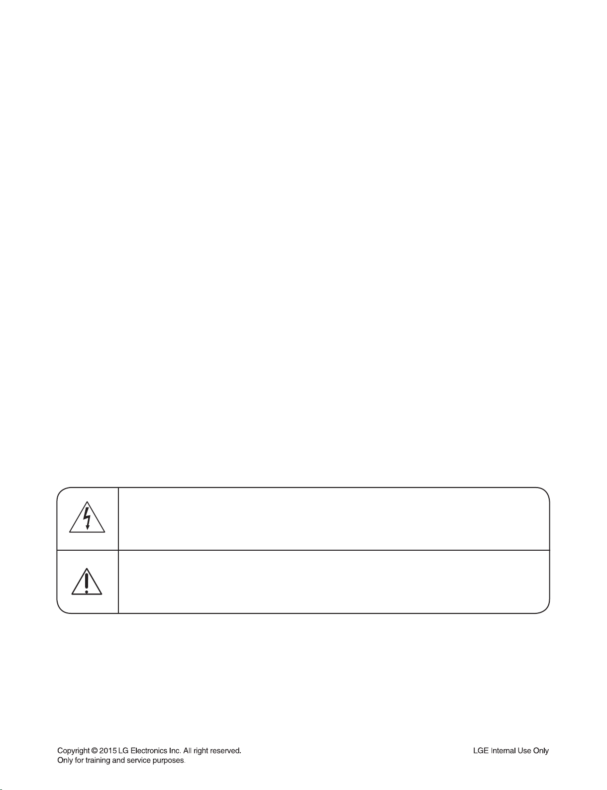
CAUTION. GRAPHIC SYMBOLS
THE LIGHTNING FLASH WITH APROWHEAD SYMBOL. WITHIN AN EQUILATERAL TRIANGLE, IS
INTENDED TO ALERT THE SERVICE PERSONNEL TO THE PRESENCE OF UNINSULATED
“DANGEROUS VOLTAGE” THAT MAY BE OF SUFFICIENT MAGNITUDE TO CONSTITUTE A RISK OF
ELECTRIC SHOCK.
THE EXCLAMATION POINT WITHIN AN EQUILATERAL TRIANGLE IS INTENDED TO ALERT THE
SERVICE PERSONNEL TO THE PRESENCE OF IMPORTANT SAFETY INFORMATION IN SERVICE
LITERATURE.
1-5
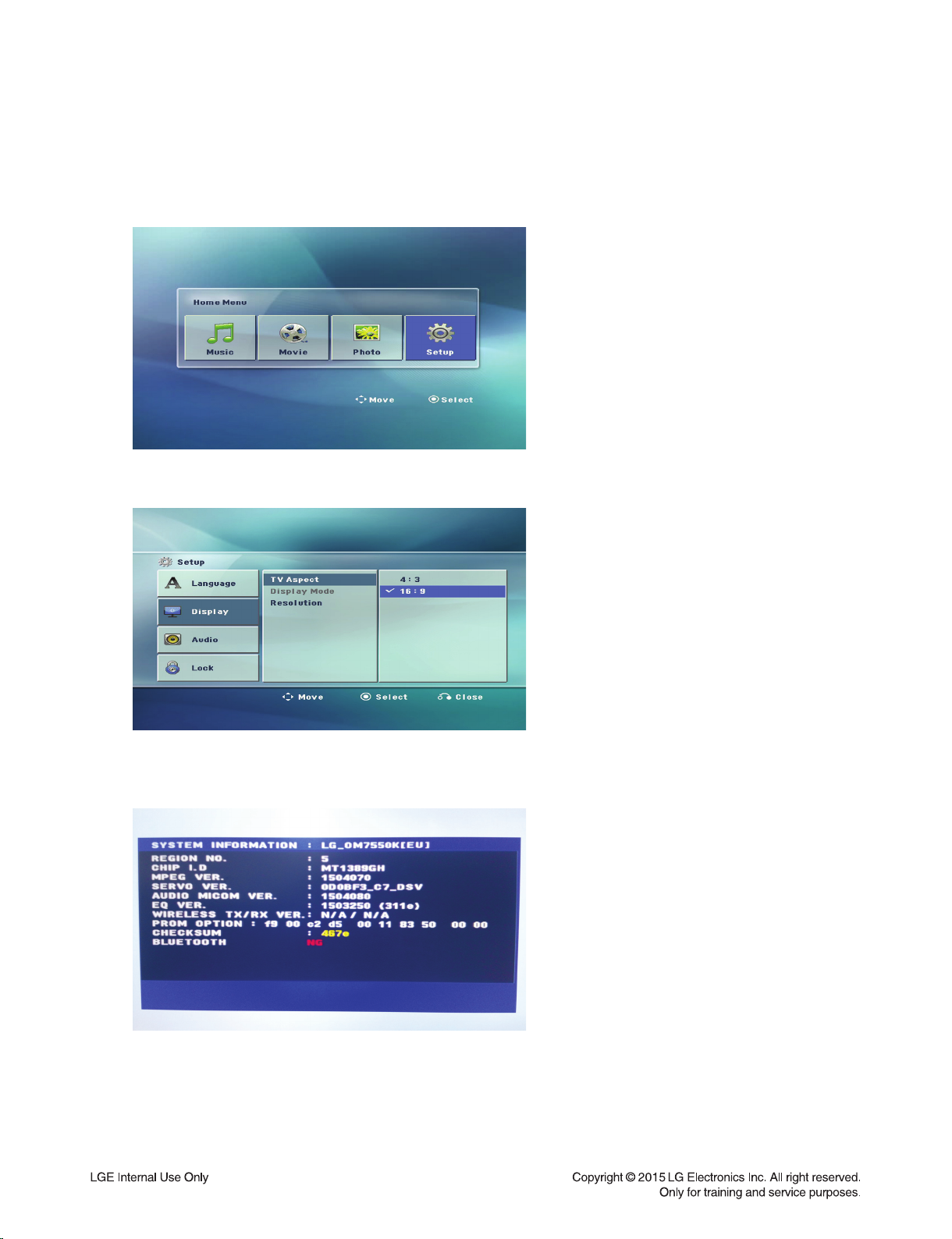
HIDDEN KEY MODE
1. DISPLAY SYSTEM INFORMATION
1) Change function to DVD/CD by pressing input key, and wait until home menu is shown.
- Do not insert disc or USB at the set.
2) Go to SETUP menu by pressing SETUP button in HOME menu.
3) Move highlight at "DISPLAY -> TV Aspect -> 16:9".
4) Press "1 -> 3 -> 9 -> 7 -> 1 -> 3 -> 9 -> ENTER" in order.
5) and then, system reset menu is displayed.
6) Power off and on by pressing POWER key.
1-6

2. EEPROM EDIT
1) Change function to DVD/CD by pressing input key, and wait until home menu is shown.
- Do not insert disc or USB at the set.
2) Press "PAUSE -> 1 -> 4 -> 7 -> 2" in order.
3) and then, option setting menu is displayed.
You can see 10 bytes option value.
4) Move a cursor by pressing Arrow < > key.
5) Press number 0 ~ 9, character a ~ f (1 ~ 6 for a while) for more than 5 seconds
6) Press "PAUSE" key to exit option setting menu.
After change option value, you need to make system reset.
3. DOOR LOCK / UNLOCK
1) Press Front “STOP” + Remote control “STOP” for more than 5 seconds.
2) “LOCKED” / “UNLOCKED” display on the VFD.
1-7

FIRMWARE UPGRADE GUIDE
1. MPEG
1) Copy fi rmware to USB (Do not change fi le name).
Ex) LG_OM7550KLD1_1503260.ROM
2) Change function to DVD/CD by pressing input key, and wait until home menu is shown.
3) Inset USB device which includes fi rmware.
4) Firmware is detected automatically and then, shows blue screen in TV.
If home menu is maintained after inserting USB, press music icon.
5) Take off the USB and press PLAY key.
6) And then, upgrading is started.
- Do not turn off the set until upgrade is fi nished.
7) After fi nishing fi rmware upgrading, set will display search.
8) Power off and on again by pressing POWER key.
1-8
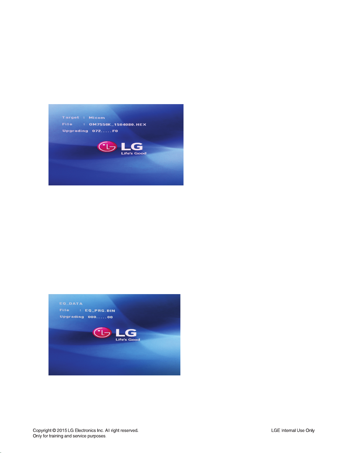
2. AUDIO MICOM
1) Copy fi rmware to USB (Do not change fi le name).
Ex) OM7550K_1503300.HEX
2) Change function to DVD/CD by pressing input key, and wait until home menu is shown.
3) Inset USB device which includes fi rmware.
4) Firmware is detected automatically and then, shows blue screen in TV.
If home menu is maintained after inserting USB, press music icon.
5) Upgrading is started.
- Do not turn off the set until upgrade is fi nished.
- Do not pull out the USB device using fi rmware upgrading.
6) After fi nishing fi rmware upgrading, set will be turned off.
3. EQ
1) Copy fi rmware to USB (Do not change fi le name).
Ex) EQ_PRG.BIN
2) Change function to DVD/CD by pressing input key, and wait until home menu is shown.
3) Inset USB device which includes fi rmware.
4) Firmware is detected automatically and then, shows blue screen in TV.
If Home menu is maintained after inserting USB, press music icon.
5) Upgrading is started.
- Do not turn off the set until upgrade is fi nished.
- Do not pull out the USB device using fi rmware upgrading.
6) After fi nishing fi rmware upgrading, set will be turned off.
1-9

SPECIFICATIONS
• GENERAL
Power requirements Refer to the main label.
Power consumption Refer to the main label.
Networked standby : 0.4 W
(If all network ports are activated.)
Dimensions (W x H x D) 430 mm x 655 mm x 478 mm
Net Weight (Approx.) 21 kg
Operating temperature 5 °C to 35 °C (41 °F to 95 °F)
Operating humidity 60 %
Bus Power Supply 5 V 500 mA
• INPUTS
AUX IN 2.0 Vrms (1 kHz, 0 dB), 600 Ω, RCA jack (L, R)
PORT. IN 1.4 Vrms (3.5 Ø jack)
MIC 20 mV
• TUNER
FM Tuning Range 87.5 to 108.0 MHz or 87.50 to 108.00 MHz
• CD
Frequency Response 40 to 20 000 Hz
Signal-to-noise ratio 75 dB
Dynamic range 75 dB
• AMPLIFIER
Total output 1000 W
FRONT 500 W (6 Ω at 100 Hz)
MID 500 W (6 Ω at 1 kHz)
THD 20 %
• SPEAKER
Type Front : 1 Way 1 Speaker
MID : 2 Way 2 Speaker
Impedance Front : 6 Ω
MID : 6 Ω
• Design and specifications are subject to change without notice.
1-10

SECTION 2
CABINET & MAIN CHASSIS
CONTENTS
DISASSEMBLY INSTRUCTIONS ..................................................................................................................... 2-2
1. HOW TO DISASSEMBLE THE SIDE COVER (LEFT & RIGHT) ............................................................. 2-2
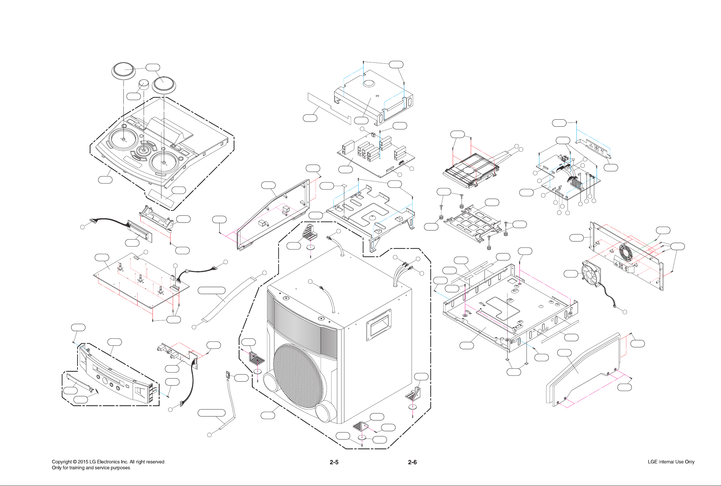
EXPLODED VIEWS ........................................................................................................................................... 2-5
1. CABINET AND MAIN FRAME SECTION ................................................................................................. 2-5
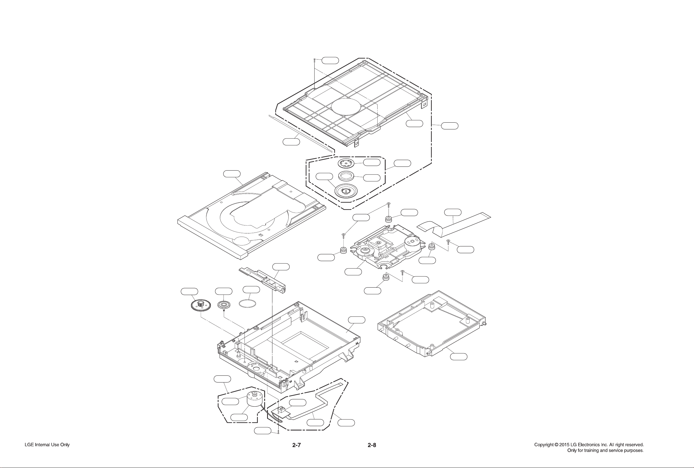
2. DECK MECHANISM SECTION (DM19) ................................................................................................... 2-7
3. PACKING ACCESSORY SECTION ......................................................................................................... 2-9
2-1
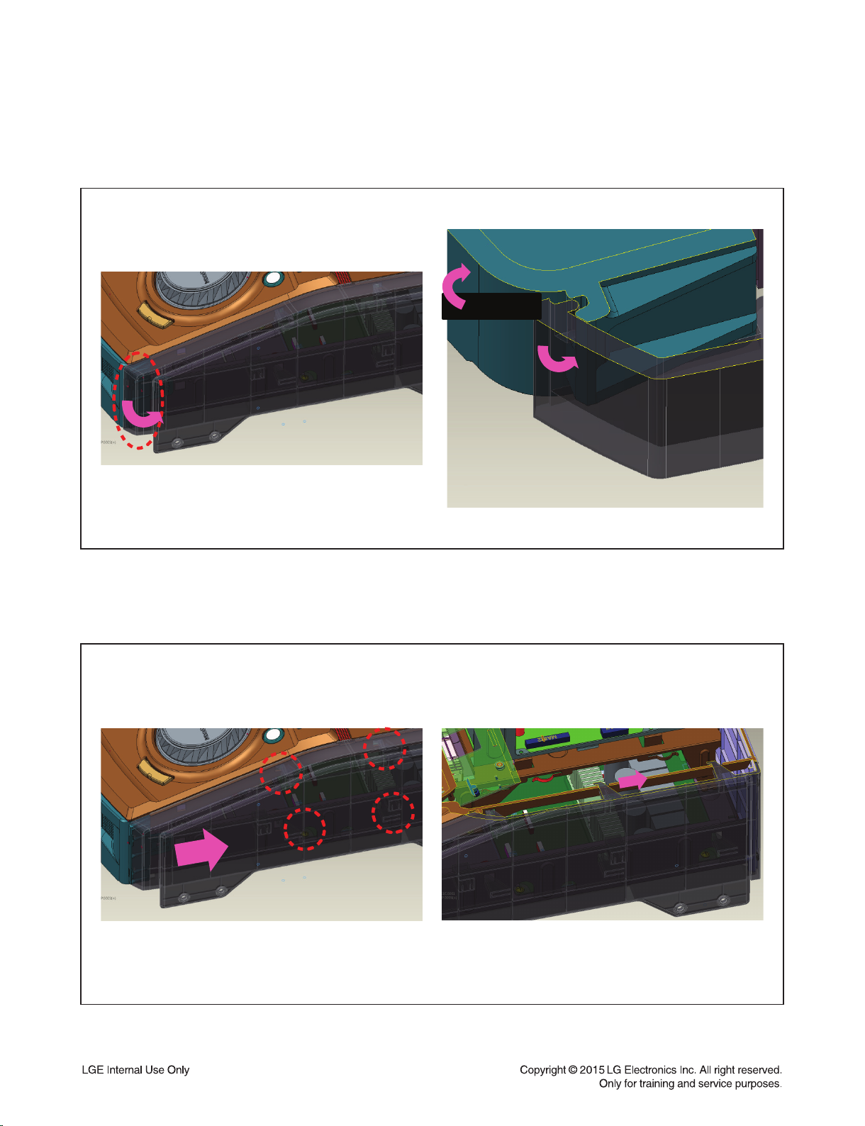
DISASSEMBLY INSTRUCTIONS
1. HOW TO DISASSEMBLE THE SIDE COVER (LEFT & RIGHT)
Step 1) Insert JIG into groove and then raise Cover_Side with a lever(JIG) to outside direction.
-,*
Figure 1
Step 2) Tap(Push-silde) Cover_Side to back direction.
Figure 2
2-2
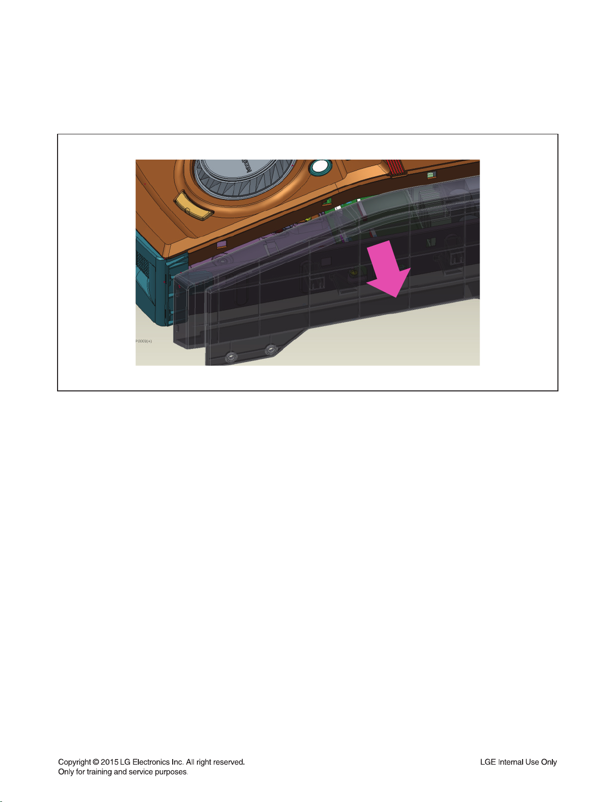
Step 3) Seperate Cover_Side to out direction.
Figure 3
2-3

2-4
J
A
L
M
O
Q
K
P
B
G
C
E
D
K
F
C
A
B
N
P
Q
F
J
G
E
D
N
L
M
O
I
I
TOP
MAIN
SMPS
VFD
FRONT
B/T
468
A52
255
256
468
468
468
263
264
265
266
267
268
270
A46
468
468
443
443
285
286
284
283
282
282
468
A47
443
443
512
470
512
260
262
261
A41
250
251
443
A44
254
A43
A42
443
A49
A50
275
277
276
279
512
512
278
252
468
512
512
468
443
518
518
CABLE4
CABLE1
281
EXPLODED VIEWS
1. CABINET AND MAIN FRAME SECTION
1439
A001
1002
1043
A005
1016
1013
1015
1020
1439
1018
1019
1012
A006
1045
1026
1049
1437
1437
1024
1024
1024
1024
1437
1005
1001
1003
1006
1004
1011
1030
2. DECK MECHANISM SECTION (DM19)
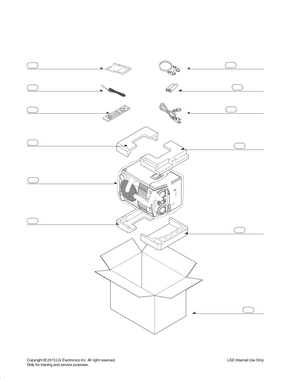
3. PACKING ACCESSORY SECTION
801 Owner’s manual
825 FM Antenna
900 Remote Control
803 Packing
804 Bag
823 HDMI Cable
808 Batteries
300 Power Cord
803 Packing
803 Packing
803 Packing
802 Box
2-9

2-10

SECTION 3 ELECTRICAL
CONTENTS
DIGITAL DISPLAY & MEDIA TRAINING MASTER ............................................................................................................. 3-2
1. DISTORTED PICTURE .............................................................................................................................................. 3-2
2. NO PICTURE .............................................................................................................................................................3-7
3. PICTURE COLOR .................................................................................................................................................... 3-12
4. NOISE/AUDIO PROBLEMS ..................................................................................................................................... 3-14
5. MISCELLANEOUS ................................................................................................................................................... 3-17
ONE POINT REPAIR GUIDE .............................................................................................................................................. 3-26
1. NO POWER ............................................................................................................................................................. 3-26
2. VFD IS NOT DISPLAYED WHEN POWER ON THE SET ......................................................................................3-27
3. NO AMP POWER..................................................................................................................................................... 3-28
4. NO BOOTING WHEN YOU TURN THE UNIT ON, NO MESSAGE ON FRONT PANEL ....................................... 3-29
5. BAD HDMI VIDEO / AUDIO OUTPUT ..................................................................................................................... 3-35
6. NO AUDIO FROM SPEAKER .................................................................................................................................. 3-36
7. NO USB .................................................................................................................................................................... 3-37
8. BT CONNECTION ERROR...................................................................................................................................... 3-38
9. NO OPERATION OF MD ......................................................................................................................................... 3-39
ELECTRICAL TROUBLESHOOTING GUIDE ..................................................................................................................... 3-40
1. SYSTEM POWER SUPPLY ON SMPS BOARD ..................................................................................................... 3-40
2. POWER SUPPLY ON MAIN BOARD ......................................................................................................................3-43
3. SYSTEM PART ........................................................................................................................................................ 3-45
4. NO HDMI OUTPUT .................................................................................................................................................. 3-47
5. NO AUDIO OUTPUT ................................................................................................................................................ 3-48
6. NO LIGHTING (SPEAKER LED) ............................................................................................................................. 3-53
DETAILS AND WAVEFORMS ON SYSTEM TEST AND DEBUGGING ........................................................................... 3-54
1. SYSTEM PART (MPEG CRYSTAL 27 MHz) ........................................................................................................... 3-54
2. SDRAM CLOCK ....................................................................................................................................................... 3-54
3. HDMI PART .............................................................................................................................................................. 3-55
4. SERVO OPEN/CLOSE SIGNAL .............................................................................................................................. 3-56
WIRING DIAGRAM .............................................................................................................................................................. 3-65
BLOCK DIAGRAMS ............................................................................................................................................................ 3-67
1. SYSTEM BLOCK DIAGRAM.................................................................................................................................... 3-67
2. SMPS BLOCK DIAGRAM ........................................................................................................................................ 3-69
3. POWER BLOCK DIAGRAM ..................................................................................................................................... 3-71
CIRCUIT DIAGRAMS .......................................................................................................................................................... 3-73
1. SMPS_POWER #1 CIRCUIT DIAGRAM ................................................................................................................. 3-73
2. SMPS_POWER #2 CIRCUIT DIAGRAM ................................................................................................................. 3-75
3. MAIN_MICOM CIRCUIT DIAGRAM......................................................................................................................... 3-77
4. MAIN_POWER & I/O CIRCUIT DIAGRAM .............................................................................................................. 3-79
5. MAIN_ADC/ LINE OUT CIRCUIT DIAGRAM........................................................................................................... 3-81
6. MAIN_PWM CIRCUIT DIAGRAM ............................................................................................................................3-83
7. MAIN_AMP CIRCUIT DIAGRAM .............................................................................................................................3-85
8. MAIN_VFD-POWER/ LED CIRCUIT DIAGRAM ...................................................................................................... 3-87
9. MAIN_MPEG CIRCUIT DIAGRAM .......................................................................................................................... 3-89
10. MAIN_SERVO CIRCUIT DIAGRAM ......................................................................................................................... 3-91
11. FRONT CIRCUIT DIAGRAM .....................................................................................................
12. VFD/RMC1 CIRCUIT DIAGRAM .............................................................................................................................. 3-95
13. TOP(VOLUME_FR1) CIRCUIT DIAGRAM .............................................................................................................. 3-97
CIRCUIT VOLTAGE CHART ............................................................................................................................................... 3-99
1. ICs ............................................................................................................................................................................ 3-99
2. CAPACITORS ........................................................................................................................................................ 3-100
............................... 3-93
PRINTED CIRCUIT BOARD DIAGRAMS ......................................................................................................................... 3-101
1. SMPS P. C. BOARD (TOP VIEW) ......................................................................................................................... 3-101
2. SMPS P. C. BOARD (BOTTOM VIEW) ................................................................................................................. 3-103
3. MAIN, FRONT, VFD/RMC1 P.C.BOARD (TOP VIEW) ......................................................................................... 3-105
4. MAIN, FRONT, VFD/RMC1 P.C.BOARD (BOTTOM VIEW) ................................................................................. 3-107
5. TOP(VOLUME_FR1) P.C.BOARD (TOP VIEW) .................................................................................................... 3-109
6. TOP(VOLUME_FR1) P.C.BOARD (BOTTOM VIEW) ............................................................................................ 3-111
3-1
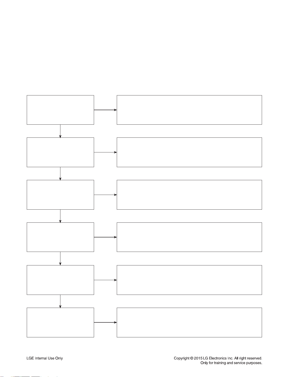
DIGITAL DISPLAY & MEDIA TRAINING MASTER
Objective: To provide clear and concise guidelines for customer service agents to handle calls on
box goods calls.
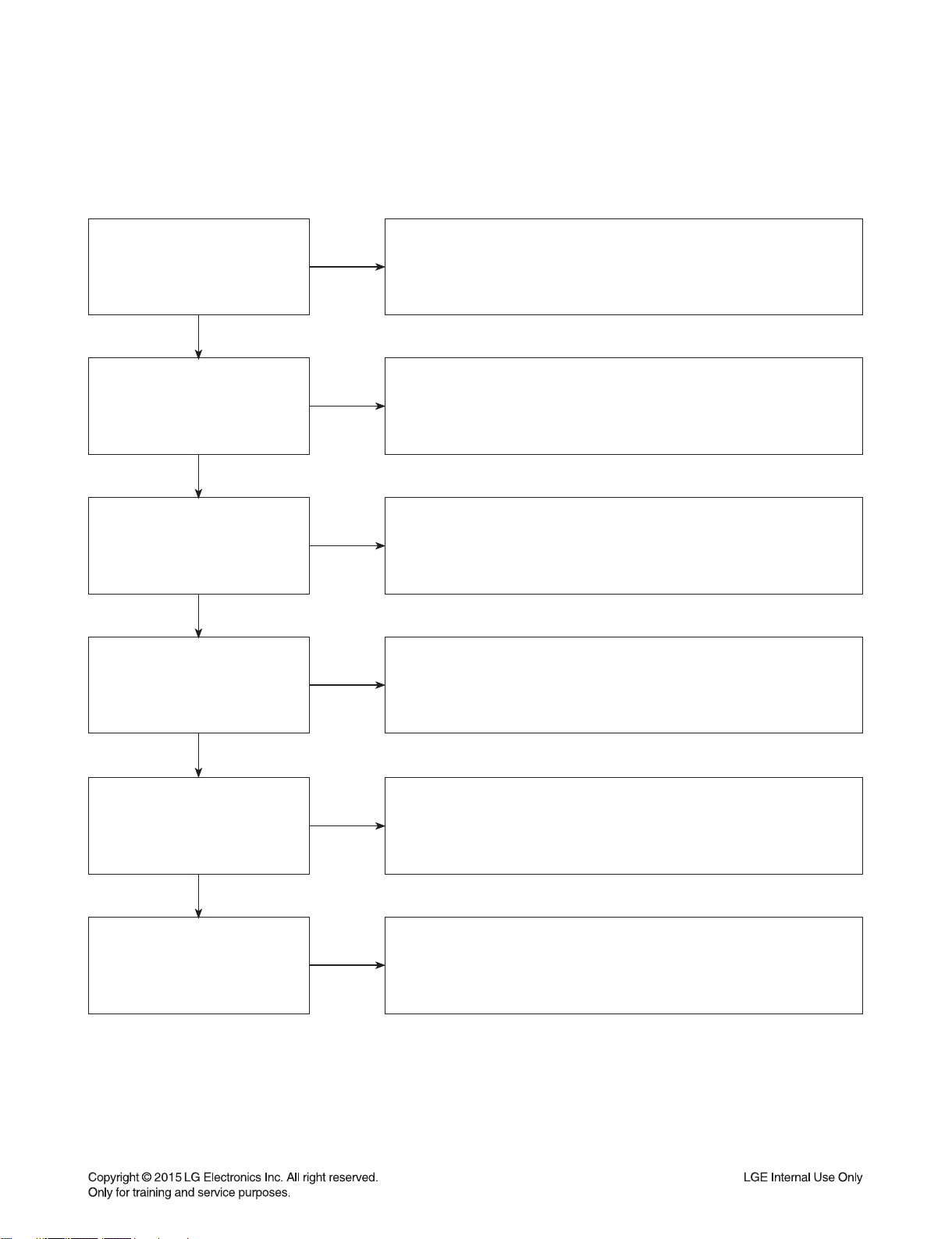
1. DISTORTED PICTURE
1-1. Lines on Picture
Distorted picture refers to the customer getting video, but there is a problem with the video.
Determine what cables the customer is using to connect
What cables is
the customer using to
connect the DVD?
YES
NO
the DVD to the TV and if connected properly. Refer to OM for
connections. Tighten any loose cables. Make sure the customer
is not connecting a DVD to VCR.
Copy protection can distort the picture on older DVD models.
Is the TV set
to the correct input?
YES
Do lines appear when
watching multiple discs?
YES
Do lines appear when
watching a TV program?
YES
Do lines appear
when the DVD is
connected to another TV?
NO
NO
NO
NO
Make sure the TV is on the correct input.
Turn TV off, then on to determine input.
Video when using composite, or component.
DVI when using DVI, and HDMI when using HDMI.
One disc displaying the issue is a problem with the disc.
Multiple discs displaying the problem could indicate the DVD lens
needs to be cleaned. Recommend the customer use a lens
cleaner on the DVD. A lens cleaner is available at any local
electronics retailer.
Lines appearing when watching a TV program indicates
an issue with the display. If the TV program is fine,
then connect the DVD to another input on the display to
determine if the problem is following the DVD.
Connect the DVD to another TV and play a disc.
No lines during disc play back indicates a problem with the first TV.
Please refer to the owners manual for instructions on how to
connect the DVD to a TV. If the DVD has a problem on the
second TV, then see service chart for service information.
YES
Has the customer tried
another set of cables?
NO
Have the customer try another set of cables. A bad cable can
also cause video problems. Test the cable with another device to
the TV to also determine if the TV is bad. If DVD is problem,
please see service chart for service information.
3-2

DIGITAL DISPLAY & MEDIA TRAINING MASTER
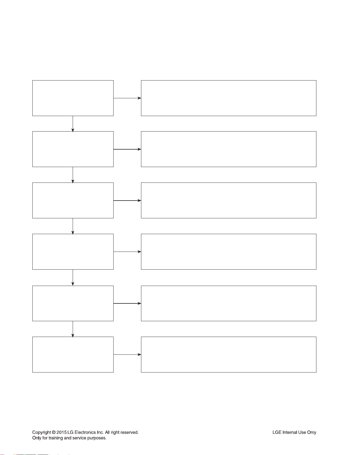
1-2. Ghost Picture
Distorted picture refers to the customer getting video, but there is a problem with the video.
Determine what cables the customer is using to connect the DVD to
What cables is the customer
using to connect the DVD?
YES
NO
the TV and if connected properly. Refer to OM for connections.
Tighten any loose cables. Make sure the customer is not connecting a
DVD to VCR or DVD. Copy protection can distort
the picture on older VCR models.
Is the TV set to
the correct input?
YES
Do ghosting appear when
watching multiple discs?
YES
Do lines appear when
watching a TV program?
YES
Does ghosting
appear when the DVD is
connected to another TV?
NO
NO
NO
NO
Make sure the TV is on the correct input. Turn TV off,
then on to determine input. Video when using composite,
or component. DVI when using DVI, and HDMI when using HDMI.
One disc displaying the issue is a problem with the disc.
Multiple discs displaying the problem could indicate the DVD lens
needs to be cleaned. Recommend the customer use a lens cleaner
on the DVD. A lens cleaner is available at any local electronics retailer.
Ghosting appearing when watching a TV program indicates an
issue with the display. If the TV program is fine, then connect
the DVD to another input on the display to determine
if the problem is following the DVD.
Connect the DVD to another TV and play a disc.
No ghosting during disc play back indicates a problem with the first TV.
Please refer to the owners manual for instructions on how to
connect the DVD to a TV. If the DVD has a problem on the second TV,
then see service chart for service information.
YES
Has the customer tried
another set of cables?
NO
Have the customer try another set of cables. A bad cable can
also cause video problems. Test the cable with another device to
the TV to also determine if the TV is bad. If DVD is problem,
please see service chart for service information.
3-3

DIGITAL DISPLAY & MEDIA TRAINING MASTER
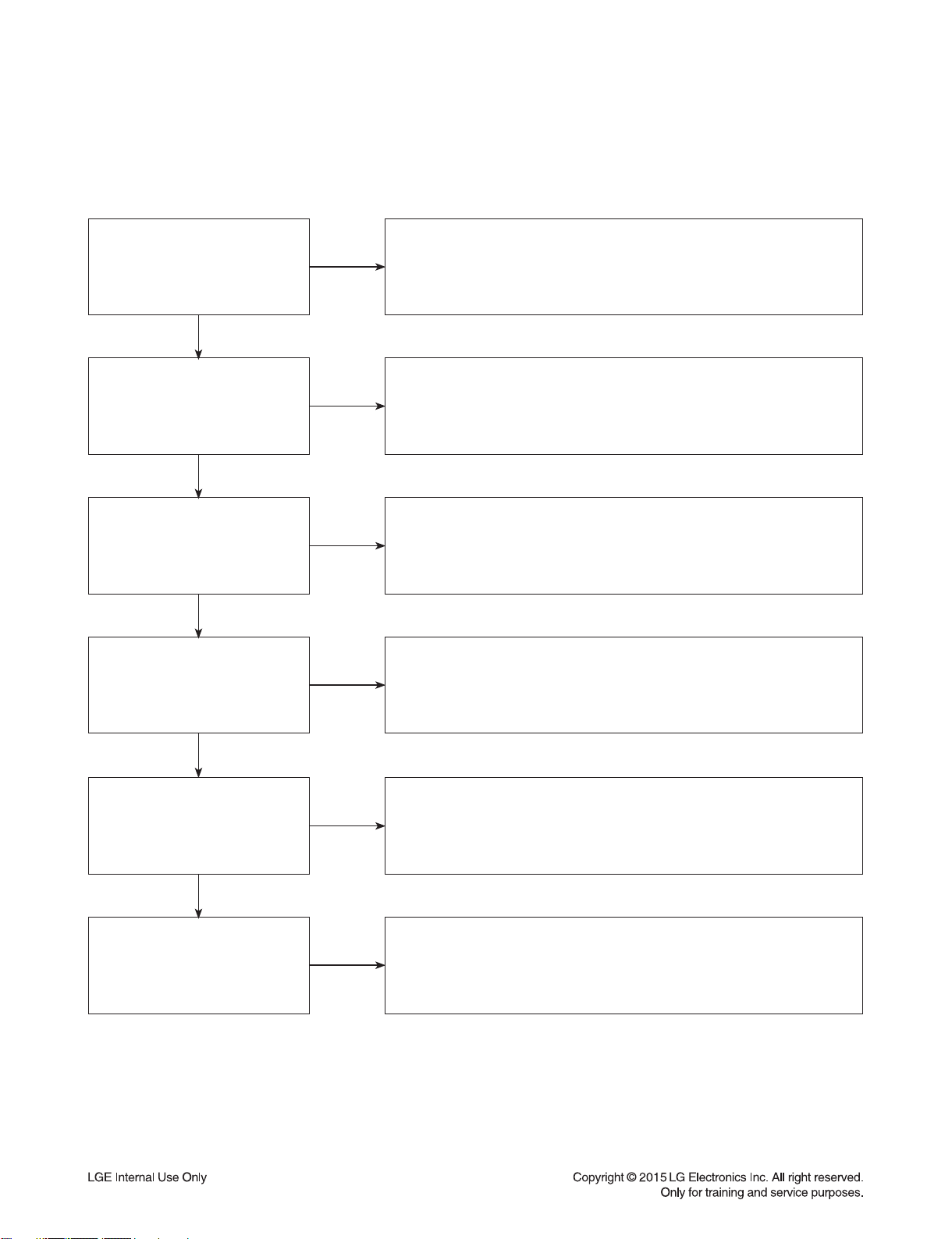
1-3. Rolling Picture
Distorted picture refers to the customer getting video, but there is a problem with the video.
Determine what cables the customer is using to connect the DVD to
What cables is the customer
using to connect the DVD?
YES
NO
the TV and if connected properly. Refer to OM for connections.
Tighten any loose cables. Make sure the customer is not connecting
a DVD to VCR. Copy protection can distort
the picture on older VCR models.
Is the TV set to
the correct input?
YES
Does rolling appear when
watching multiple discs?
YES
Does rolling appear when
watching a TV program?
YES
Does rolling appear
when the DVD is connected to
another TV?
NO
NO
NO
NO
Make sure the TV is on the correct input. Turn TV off,
then on to determine input. Video when using composite,
or component. DVI when using DVI, and HDMI when using HDMI.
One disc displaying the issue is a problem with the disc.
Multiple discs displaying the problem could indicate the DVD lens
needs to be cleaned. Recommend the customer use a lens cleaner
on the DVD. A lens cleaner is available at any local electronics retailer.
Rolling appearing when watching a TV program indicates
an issue with the display. If the TV program is fine, then connect
the DVD to another input on the display to determine if the problem
is following the DVD.
Connect the DVD to another TV and play a disc. No lines during disc
playback indicates a problem with the first TV.
Please refer to the owners manual for instructions on how to connect the
DVD to a TV. If the DVD has a problem on the second TV,
then see service chart for service information.
YES
Has the customer tried
another set of cables?
NO
Have the customer try another set of cables. A bad cable can also
cause video problems. Test the cable with another device to the TV
to also determine if the TV is bad. If DVD is problem,
please see service chart for service information.
3-4
DIGITAL DISPLAY & MEDIA TRAINING MASTER
1-4. Shaky Picture
Distorted picture refers to the customer getting video, but there is a problem with the video.
Determine what cables the customer is using to connect the DVD to
What cables is the customer
using to connect the DVD?
YES
NO
the TV and if connected properly. Refer to OM for connections.
Tighten any loose cables.
Make sure the customer is not connecting a DVD.
Copy protection can distort the picture on older VCR models.
Is the TV set to
the correct input?
YES
Does shaking appear when
watching multiple discs?
YES
Does shaking appear when
watching a TV program?
YES
Does shaking appear
when the DVD is connected to
another TV?
NO
NO
NO
NO
Make sure the TV is on the correct input. Turn TV off, then on
to determine input. Video when using composite, or component.
DVI when using DVI, and HDMI when using HDMI.
One disc displaying the issue is a problem with the disc.
Multiple discs displaying the problem could indicate the DVD lens
needs to be cleaned. Recommend the customer use a lens cleaner
on the DVD. A lens cleaner is available at any local electronics retailer.
Shaking appearing when watching a TV program indicates an issue with
the display. If the TV program is fine, then connect the DVD to another
input on the display to determine if the problem is following the DVD.
Connect the DVD to another TV and play a disc. No shaking during
disc play back indicates a problem with the first TV. Please refer to
the owners manual for instructions on how to connect the DVD to a TV.
If the DVD has a problem on the second TV,
then see service chart for service information.
YES
Has the customer tried
another set of cables?
NO
Have the customer try another set of cables. A bad cable can
also cause video problems. Test the cable with another device to
the TV to also determine if the TV is bad. If DVD is problem,
please see service chart for service information.
3-5

DIGITAL DISPLAY & MEDIA TRAINING MASTER
1-5. Blurry Picture
Distorted picture refers to the customer getting video, but there is a problem with the video.
Determine what cables the customer is using to connect the DVD to
What cables is the customer
using to connect the DVD?
YES
NO
the TV and if connected properly. Refer to OM for connections.
Tighten any loose cables. Make sure the customer is not connecting
a DVD to VCR. Copy protection can distort
the picture on older VCR models.
Is the TV set to
the correct input?
YES
Does blurriness appear when
watching multiple discs?
YES
Does blurriness appear when
watching a TV program?
YES
Does blurriness appear
when the DVD is connected to
another TV?
NO
NO
NO
NO
Make sure the TV is on the correct input. Turn TV off,
then on to determine input. Video when using composite, or component.
DVI when using DVI, and HDMI when using HDMI.
One disc displaying the issue is a problem with the disc.
Multiple discs displaying the problem could indicate the DVD lens
needs to be cleaned. Recommend the customer use a lens cleaner on
the DVD. A lens cleaner is available at any local electronics retailer.
Blurriness appearing when watching a TV program indicates an
issue with the display. If the TV program is fine, then connect
the DVD to another input on the display to determine if the problem
is following the DVD.
Connect the DVD to another TV and play a disc. No blurriness
during disc play back indicates a problem with the first TV.
Please refer to the owners manual for instructions on how to connect
the DVD to a TV. If the DVD has a problem on the second TV,
then see service chart for service information.
YES
Has the customer tried
another set of cables?
NO
Have the customer try another set of cables.
A bad cable can also cause video problems. Test the cable with another
device to the TV to also determine if the TV is bad. If DVD is problem,
please see service chart for service information.
3-6
DIGITAL DISPLAY & MEDIA TRAINING MASTER
2. NO PICTURE
2-1. Black Screen
The entire screen is black.
Does the DVD on-screen
menu appear?
YES
What cables is the customer
using to connect the DVD?
YES
Is the TV set to
the correct input?
YES
Is the customer able to
watch TV programming?
NO
NO
NO
NO
Make sure the customer did not select 480i resolution in the menu
of the DVD HTS if using HDMI connections. Change resolution on
upconversion DVD HTS by pushing the resolution button of the remote
controller. HDMI don’t support 480i resolution.
Determine what cables the customer is using to connect the DVD to
the TV and if connected properly. Refer to OM for connections.
Tighten any loose cables. Make sure the customer is not connecting a
DVD to VCR. Copy protection can distort
the picture on older VCR models.
Make sure the TV is on the correct input. Turn TV off,
then on to determine input. Video when using composite, or component.
DVI when using DVI, and HDMI when using HDMI.
If the customer is not able to watch television then he may have a
problem with his television, especially if the cable signal comes
through on a different input. If the customer can not get a TV program,
then he still may have a problem with the particular input on his TV.
YES
Can the customer connect
the DVD to another TV?
YES
Has the customer tried
another set of cables?
NO
NO
Have the customer connect the DVD to another TV in order to
determine if the problem is the DVD or the TV. Refer to the OM for
connections assistance. If the DVD works on the second TV,
then the customer has a problem with his TV.
Have the customer try another set of cables. A bad cable can
also cause video problems. Test the cable with another device to the TV
to also determine if the TV is bad. If DVD is problem,
please see service chart for service information.
3-7

DIGITAL DISPLAY & MEDIA TRAINING MASTER
2-2. Blue Screen
The entire screen is a solid blue color.
Does the DVD on-screen
menu appear?
YES
What cables is the customer
using to connect the DVD?
YES
Is the TV set to
the correct input?
YES
Is the customer able to
watch TV programming?
NO
NO
NO
NO
Make sure the customer did not select 480i resolution in the menu
of the DVD HTS if using HDMI connections. Change resolution on
upconversion DVD HTS by pushing the resolution button of the remote
controller. HDMI don’t support 480i resolution.
Determine what cables the customer is using to connect the DVD
to the TV and if connected properly. Refer to OM for connections.
Tighten any loose cables. Make sure the customer is not connecting a
DVD to VCR. Copy protection can distort
the picture on older VCR models.
Make sure the TV is on the correct input.
Turn TV off, then on to determine input. Video when using composite,
or component. DVI when using DVI, and HDMI when using HDMI.
If the customer is not able to watch television then he may have a
problem with his television, especially if the cable signal comes
through on a different input. If the customer can not get a TV program,
then he still may have a problem with the particular input on his TV.
YES
Can the customer connect
the DVD to another TV?
YES
Has the customer tried
another set of cables?
NO
NO
Have the customer connect the DVD to another TV in order to
determine if the problem is the DVD or the TV. Refer to the OM for
connections assistance. If the DVD works on the second TV,
then the customer has a problem with his TV.
Have the customer try another set of cables. A bad cable can also
cause video problems. Test the cable with another device to
the TV to also determine if the TV is bad. If DVD is problem,
please see service chart for service information.
3-8

DIGITAL DISPLAY & MEDIA TRAINING MASTER
2-3. Snowy Screen
A snowy picture is when black and white dots are all over the screen.
Does the DVD on-screen
menu appear?
YES
What cables is the customer
using to connect the DVD?
YES
Is the TV set to
the correct input?
YES
Is the customer able to
watch TV programming?
NO
NO
NO
NO
Make sure the customer did not select 480i resolution in the menu
of the DVD HTS if using HDMI connections. Change resolution on
upconversion DVD HTS by pushing the resolution button of the remote
controller. HDMI don’t support 480i resolution.
Determine what cables the customer is using to connect the DVD
to the TV and if connected properly. Refer to OM for connections.
Tighten any loose cables. Make sure the customer is not connecting a
DVD to VCR. Copy protection can distort
the picture on older VCR models.
Make sure the TV is on the correct input. Turn TV off,
then on to determine input. Video when using composite, or component.
DVI when using DVI, and HDMI when using HDMI.
If the customer is not able to watch television then he may
have a problem with his television, especially if the cable signal comes
through on a different input. If the customer can not get a TV program,
then he still may have a problem with the particular input on his TV.
YES
Can the customer connect
the DVD to another TV?
YES
Has the customer tried
another set of cables?
NO
NO
Have the customer connect the DVD to another TV in order to
determine if the problem is the DVD or the TV. Refer to the OM for
connections assistance. If the DVD works on the second TV,
then the customer has a problem with his TV.
Have the customer try another set of cables. A bad cable can
also cause video problems. Test the cable with another device to
the TV to also determine if the TV is bad. If DVD is problem,
please see service chart for service information.
3-9
DIGITAL DISPLAY & MEDIA TRAINING MASTER
2-4. No Signal
A “no signal” message appears on the screen of the display.
Does the DVD on-screen
menu appear?
YES
What cables is the customer
using to connect the DVD?
YES
Is the TV set to the
correct input?
YES
Is the customer able to
watch TV programming?
NO
NO
NO
NO
Make sure the customer did not select 480i resolution in the
menu of the DVD HTS if using HDMI connections. Change resolution on
upconversion DVD HTS by pushing the resolution button of the remote
controller. HDMI don’t support 480i resolution.
Determine what cables the customer is using to connect the DVD
to the TV and if connected properly. Refer to OM for connections.
Tighten any loose cables. Make sure the customer is not connecting
a DVD to VCR or DVD to DVD Recorder.
Copy protection can distort the picture on older VCR models.
Make sure the TV is on the correct input. Turn TV off,
then on to determine input. Video when using composite, or component.
DVI when using DVI, and HDMI when using HDMI.
If the customer is not able to watch television then he may have a
problem with his television, especially if the cable signal comes
through on a different input. If the customer can not get a TV program,
then he still may have a problem with the particular input on his TV.
YES
Can the customer connect
the DVD to another TV?
YES
Has the customer tried
another set of cables?
NO
NO
Have the customer connect the DVD to another TV in order to
determine if the problem is the DVD or the TV. Refer to the OM for
connections assistance. If the DVD works on the second TV,
then the customer has a problem with his TV.
Have the customer try another set of cables. A bad cable
can also cause video problems. Test the cable with another device to
the TV to also determine if the TV is bad. If DVD is problem,
please see service chart for service information.
3-10
DIGITAL DISPLAY & MEDIA TRAINING MASTER
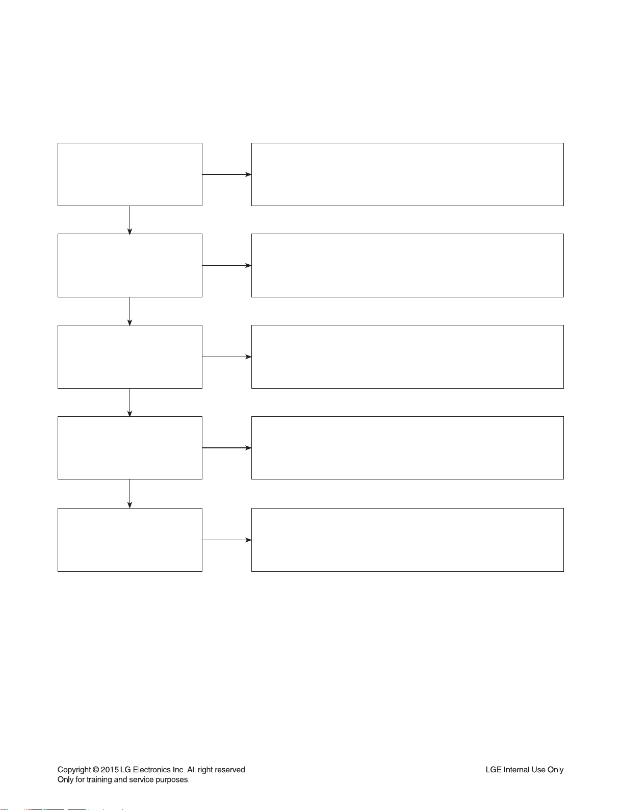
2-5. Invalid Format or Format Not Supported
Is the customer using a
digital cable connection?
YES
Is the customer using an
analog cable connection?
YES
Is the display
HDCP compliant?
YES
Has the customer tried the
device on another display?
NO
NO
NO
NO
Customer’s using an DVI, or HDMI cable connection need to set the
resolution on the product above 480I. HDMI,
DVI connections can not process a 480I resolution.
They can only process a 480P, 720P, 1080I, or 1080P resolution.
Make sure the customer’s simultaneously connecting analog component
cable with HDMI cable. And then If Copy Protected Disc is playing back,
analog component output is no picture. Only when the analog output is
480I, you can see the picture. In case of No Copy Protected Disc,
you can see the picture regardless of the resolution.
Make sure the display is HDCP compliant when using a DVI or
HDMI connection. A lack of HDCP compliancy on the display may
cause an invalid format or format not supported message to appear.
It can also cause a copy protection OSD to appear.
Ask the customer to connect the device to another display.
If the device starts working, then the problem may be the original display.
The customer will need to troubleshoot the display. If the device
still does not work, then the problem may be the device or the cable.
YES
Has the customer tried
another cable?
NO
Ask the customer to replace the cable between the device and display.
If the problem is corrected, then the problem was with the cable.
If the problem continues, then the device is the problem.
Set up service according to in warranty or out of warranty procedures.
3-11
 Loading...