

LG MH-1357M, MH-1356M, MH-1355M Service Manual

MICROWAVE OVEN
SERVICE MANUAL
MODEL: MH-1355M
MH-1356M
MH-1357M
CAUTION
BEFORE SERVICING THE UNIT, READ THE SAFETY PRECAUTIONS IN THIS MANUAL.
Website: http://biz.lgservice.com
P/NO : 3828W5S6174
July, 1998
Printed in Korea

– 2 –
SAFETY PRECAUTIONS
This device is to be serviced only by properly qualified service personnel.
Consult the Service Manual for proper service procedures to assure continued safety operation and for
precautions to be taken to avoid possible exposure to excessive microwave energy.
— Proper operation of the microwave ovens requires that the magnetron be assembled to the wave guide and
cavity. Never operate the magnetron unless it is properly installed.
— Be sure that the magnetron gasket is properly installed around the dome of the tube whenever installing the
magnetron.
— Routine service safety procedures should be exercised at all times.
— Untrained personnel should not attempt service without a thorough review of the test procedures and safety
information contained in this manual.
PRECAUTIONS TO BE OBSERVED BEFORE
AND DURING SERVICING TO AVOID POSSIBLE
EXPOSURE TO EXCESSIVE MICROWAVE
ENERGY
A) Do not operate or allow the oven to be operated with the door open.
B) Make the following safety checks on all ovens to be serviced before activating the magnetron
or other microwave source, and make repairs as necessary; (1) interlock operation, (2) proper
door closing, (3) seal and sealing surfaces (arcing, wear, and other damage), (4) damage to or
loosening of hinges and latches, (5) evidence of dropping or abuse.
C) Before turning on microwave power for any service test or inspection within the microwave
generating compartments, check the magnetron, wave guide or transmission line, and cavity
for proper alignment, integrity, and connections.
D) Any defective or misadjusted components in the interlock, monitor, door seal, and microwave
generation and transmission systems shall be repaired, replaced, or adjusted by procedures
described in this manual before the oven is released to the owner.
E) A microwave leakage check to verify compliance with the Federal Performance Standard
should be performed on each oven prior to release to the owner.

– 3 –
TABLE OF CONTENTS
SPECIFICATIONS
-----------------------------------------------------------------------------------------------------------------------
4
CAUTIONS
---------------------------------------------------------------------------------------------------------------------------------
5
INSTALLATIONS
-------------------------------------------------------------------------------------------------------------------------
6
FEATURE DIAGRAM
-------------------------------------------------------------------------------------------------------------------
7
CONTROL PANEL
-----------------------------------------------------------------------------------------------------------------------
8
HOW THE MICROWAVE/CONVECTION OVEN WORKS
-----------------------------------------------------------------
10
COOKING FLOW CHART
-----------------------------------------------------------------------------------------------------------
11
OPERATING INSTRUCTIONS
-----------------------------------------------------------------------------------------------------
12
SCHEMATIC DIAGRAM
-------------------------------------------------------------------------------------------------------------
15
CIRCUIT DESCRIPTION
-------------------------------------------------------------------------------------------------------------
18
DESCRIPTION AND FUNCTION OF COMPONENTS
---------------------------------------------------------------------
20
NECESSARY TOOLS AND MEASURING INSTRUMENTS
--------------------------------------------------------------
22
INSTALLATION AND ADJUSTMENT OF THE INTERLOCK SYSTEM
----------------------------------------------
23
INTERLOCK CONTINUITY TEST
-------------------------------------------------------------------------------------------------
25
DISASSEMBLY AND PARTS REPLACEMENT PROCEDURE
---------------------------------------------------------
26
TROUBLESHOOTING
----------------------------------------------------------------------------------------------------------------
30
COMPONENT TEST PROCEDURE
----------------------------------------------------------------------------------------------
36
PROCEDURE FOR MEASURING MICROWAVE ENERGY LEAKAGE
----------------------------------------------
42
EXPLODED VIEW AND PARTS LIST
-------------------------------------------------------------------------------------------
44
INTRODUCTION
-------------------------------------------------------------------------------------------------------------------
44
1. DOOR PARTS
-----------------------------------------------------------------------------------------------------------------
45
2. CONTROL PANEL PARTS
------------------------------------------------------------------------------------------------
46
3. OVEN CAVITY PARTS
------------------------------------------------------------------------------------------------------
47
4. OVEN INTERIOR PARTS (1)
---------------------------------------------------------------------------------------------
48
5. OVEN INTERIOR PARTS (2)
----------------------------------------------------------------------------------------------
49
6. LATCH PARTS
----------------------------------------------------------------------------------------------------------------
50
7. BASE PLATE PARTS
-------------------------------------------------------------------------------------------------------
51
8. WIRING HARNESS PARTS
-----------------------------------------------------------------------------------------------
52
9. CIRCUIT BOARD
-------------------------------------------------------------------------------------------------------------
53
10. CIRCUIT BOARD SCHEMATIC DIAGRAM
-------------------------------------------------------------------------
54
REPLACEMENT PARTS LIST
-------------------------------------------------------------------------------------------------
55

– 4 –
SPECIFICATIONS
Power Supply
---------------------------------------------------
120 VAC, 60 Hz
Power Consumption
------------------------------------------
1400 Watts (Microwave), 12A
1580 Watts (Convection), 13.2A
Output
--------------------------------------------------------------
*850 Watts (Microwave)
1500 Watts (Convection)
Microwave Frequency
---------------------------------------
2450 MHz ± 50 MHz
High Voltage Capacitor
--------------------------------------
0.91µF, 2100V AC
High Voltage Diode
-------------------------------------------
HVR-IX
Oven Lamp
-------------------------------------------------------
125V, 25W
Timer
---------------------------------------------------------------
99 mim. 99 sec. (Microwave, Convection and Combination)
Power Control
---------------------------------------------------
MICOM
Outer Dimension
-----------------------------------------------
15" x 22
1
/4" x 1913/16" (H x W x D)
Cavity Dimension
----------------------------------------------
103/16" x 149/16" x 1411/16" (H x W x D)
Safety Device
---------------------------------------------------
Primary Interlock Switch, Secondary Interlock Switch
Monitor Switch
Fuse 15 Amp
Magnetron Thermostat
Open at 145°C ± 6°C
Close at 60°C ± 15°C
Oven Thermostat:
Open at 130°C ± 6°C
Close at 60°C ± 15°C
✽
IEC60705 Rating Standard.
✽
Specifications are subject to change without notice.
– 5 –
• DO NOT operate on a 2-wire extension cord during
repair and use.
• NEVER TOUCH any oven components or wiring
during operation.
• BEFORE TOUCHING any parts of the oven, always
remove the power plug from the outlet.
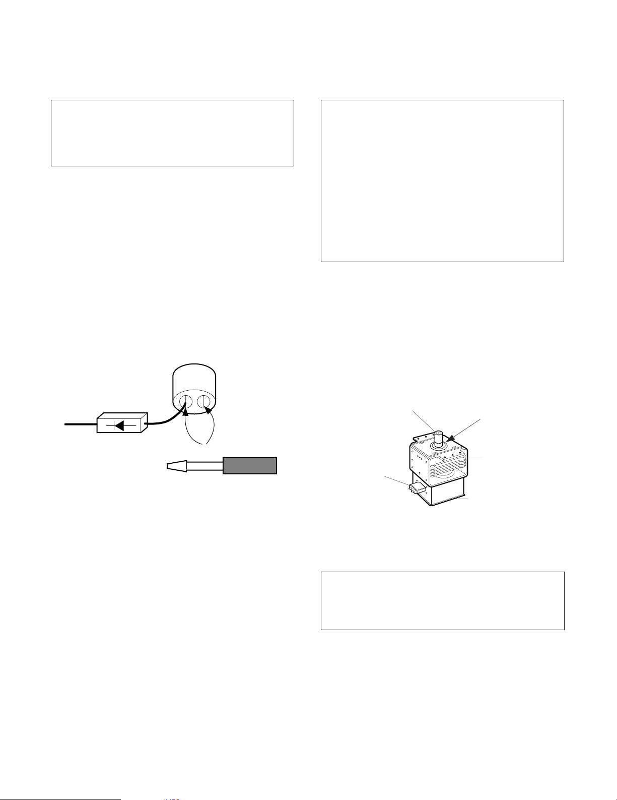
• For about 30 seconds after the oven stops, an
electric charge remains in the high voltage
capacitor. When replacing or checking, you must
discharge the high voltage capacitor by shorting
across the two terminals with an insulated
screwdriver.
• Remove your watches whenever working close to or
replacing the Magnetron.
• NEVER operate the oven with no load.
• NEVER injure the door seal and front plate of the oven
cavity.
• NEVER put iron tools on the magnetron.
• NEVER put anything into the latch hole and the
interlock switches area.
• Proper operation of the microwave oven requires
that the magnetron be assembled to the waveguide
and cavity. Never operate the magnetron unless it is
properly installed.
• Be sure that the magnetron gasket is properly
installed around the dome of the tube whenever
installing the magnetron.
CAUTIONS
Unlike other appliances, the microwave oven is
high-voltage and high-current equipment.
Though it is free from danger in ordinary use,
extreme care should be taken during repair.
THE OVEN IS TO BE SERVICED ONLY
BY PROPERLY QUALIFIED SERVICE
PERSONNEL.
MICROWAVE RADIATION
Personnel should not be exposed to the
microwave energy which may radiate from the
magnetron or other microwave generating
device if it is improperly used or connection.
All input and output microwave connections,
waveguide, flange and gasket must be secure
never operate the device without a microwave
energy absorbing load attached.
Never look into an open waveguide or antenna
while the device is energized.
Gasket
ANTENNA
COOLING FIN
MAGNETRON
CHASSIS GROUND
FILAMENT
TERMINALS
MAGNETRON

– 6 –
INSTALLATIONS
INSTALLING
1. Empty the microwave oven and clean inside it with
a soft, damp cloth. Check for damage such as
misaligned door, damage around the door or dents
inside the cavity or on the exterior.
2. Put the oven on a counter, table, or shelf that is
strong enough to hold the oven and the food and
utensils you put in it. (The control panel side of the
oven is the heavy side. Use care when handling.)
3. Do not block the vent and the air intake openings.
Blocking vent or air intake openings can cause
damage to the oven and poor cooking results.
Make sure the microwave oven legs are in place to
ensure proper air flow.
4. The oven should not be installed in any area where
heat and steam are generated, because they may
damage the electronic or mechanical parts of the
unit.
Do not install the oven next to a conventional
surface unit or above a conventional wall oven.
5. Use microwave oven in an ambient temperature
less than 104°F(40°C).
6. Place the microwave oven on a sturdy and flat
surface at least 10 cm(4 inches) from the wall.
7. Place the microwave oven as far away as possible
from TV, RADIO, COMPUTER, etc., to prevent
interference.
8. This oven must be plugged into a 15A outlet.
9. Do not touch the front glass during or after cooking
of the Grill and Combination mode.
This glass is very hot during heater operating.
10. Do not operate the oven at microwave and
combination mode with Grill rack placed in the
cavity when the oven is empty.
EARTHING INSTRUCTIONS
This microwave oven is designed to be used in a fully
earthed condition.
It is imperative, therefore, to make sure it is properly
earthed before servicing
WARNINGTHIS APPLIANCE
MUST BE EARTHED
IMPORTANT
As the colors of the wires in the mains lead of this
appliance may not correspond with the colored
markings identifying the terminals in your plug,
proceed as follows.
The wire which is colored green-and-yellow must be
connected to the terminal in the plug which is marked
with the letter E or by the earth symbol ( ) or
colored green or green-and-yellow.
The wire which is colored blue must be connected to
the terminal in the plug which is marked with the letter
N or colored black.
The wire which is colored brown must be connected
to the terminal in the plug which is marked with the
letter L or colored red.
BEFORE YOU BEGIN, READ THE FOLLOWING INSTRUCTIONS COMPLETELY AND CAREFULLY.
The wires in this mains lead are colored in
accordance with the following code:
Green-and-yellow: Earth
Blue: Neutral
Brown: Live
– 7 –
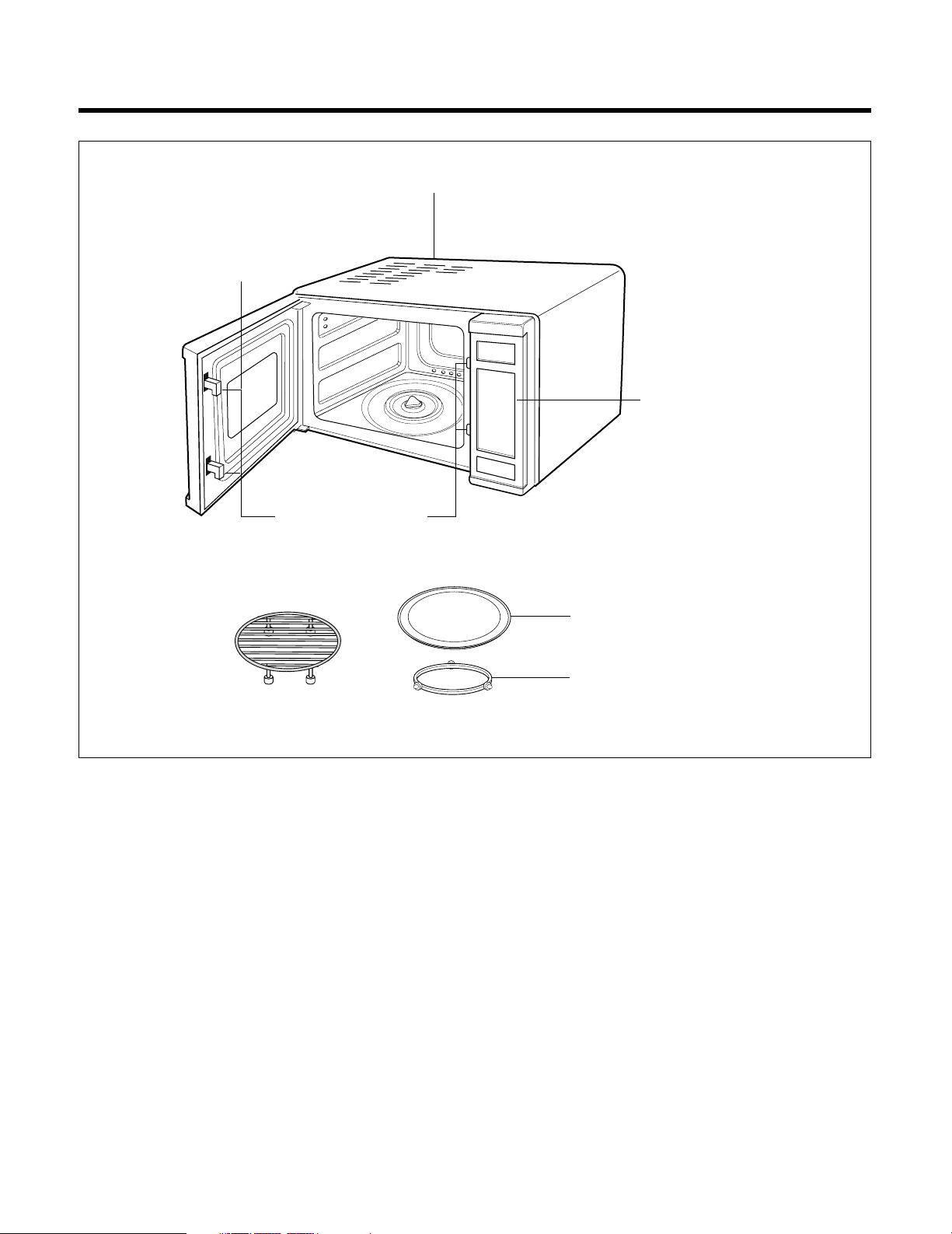
FEATURE DIAGRAM
Remove your Microwave/Convection Oven and all material from the shipping carton.
Your oven will be packed with the following material:
Turntable
---------------------------------------
1 Each
Rotating Ring Asm
--------------------------
1 Each
Convection Rack
-----------------------------
1 Each
Cookbook
---------------------------------------
1 Each
Owner’s Manual
------------------------------
1 Each
Do not use this Microwave/Convection Oven for commercial purposes.
This Microwave/Convection Oven is made for household use only.
SAFETY
INTERLOCK SYSTEM
CONVECTION RACK
TURNTABLE
ROTATING RING ASM
SEE-THROUGH
DOOR
AIR VENTS
CONTROL PANEL
Fig. 3
– 8 –
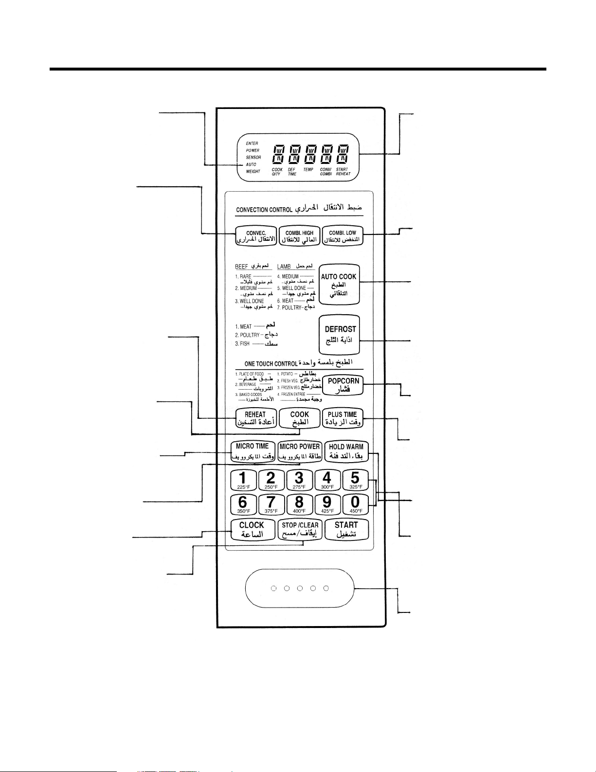
CONTROL PANEL
INDICATOR LIGHTS-
When cooking operations
are set, lights will go on
indicating the cycle in which
your oven is cooking.
DISPLAY WINDOW-
Used to show:
• Time of day.
• Cooking time.
• Cooking power level.
• Cooking temperature.
• It also functions as a
countdown timer or
temperature indicator
when cooking.
COMBINATION HIGH/LOW-
Used in setting combination
high or low cooking.
AUTO COOK- Used in
setting weight combination
cooking. Auto Combination
Guide is next to the pad.
DEFROST-
Used in setting
Auto Defrost.
POPCORN- Used to pop
pack aged popcorn.
PLUS TIME-
Used to cook
food for a longer time
after cooking end.
HOLD WARM- Used to
keep the food warm.
NUMBERS-
Used to enter the:
• Time of day.
• Cooking times.
• Cooking powers.
• Cooking temperatures.
• Weight for Auto
Combination cooking.
START-
Starts the oven.
NOTE: A “beep tone” sounds when a “pad” on the control panel is touched,
to indicate a setting has been entered.
CONVECTION-
Used in setting
convection cooking
or pre-heat.
REHEAT- Used to reheat
foods easily. Reheat Guides
is next to the pad.
COOK- Used to cook
foods easily. Cook
guide is next to the pad.
MICRO TIME- Used in
setting microwave
cooking time.
MICRO POWER-
Used to select cooking
power levels.
CLOCK- Used
to set the time of day.
STOP/CLEAR- Stops the
oven and Clears all entries
except TIME OF DAY. Once
cooking has begun, however,
CLEAR will function only after
STOP has been touched.
– 9 –
NOTE:
1. Beep Sound
The beep sound is activated under the following conditions.
Conditions Beep Sound Signal
• When the control key is touched,
• When the cooking stage is changed,
• When the preheat is ended and the holding time is begun,
• When cooking is ended,
• When an error occurs,
• When foods need to be turned over during auto weight defrost or
auto weight combination operation.
2. Microwave Cooking Power
Microwave cooking power can be chosen from one of the 10 cooking powers listed below. If cooking power is
not programmed, the oven operates at cooking power HI.
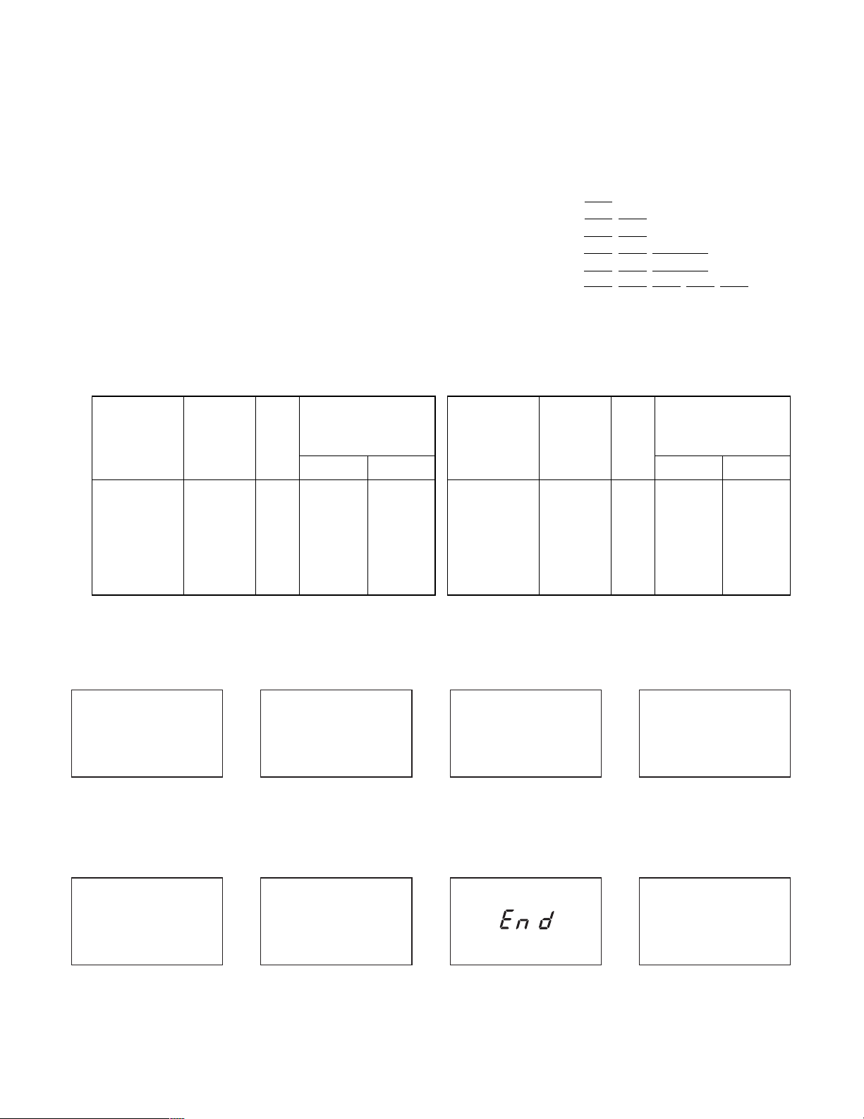
3. Digital Readout Display
Numbers
of
Touch Pads
Cooking
Power
Time
(Example: 99 min
and 99 sec)
%
Microwave
Emission Time
(sec/cycle)
ON OFF
1
2
3
4
5
10
20
30
40
50
10
20
30
40
50
4
6
8
10
12
18
16
14
12
10
Numbers
of
Touch Pads
Cooking
Power
%
Microwave
Emission Time
(sec/cycle)
ON OFF
6
7
8
9
60
70
80
90
HI
60
70
80
90
100
14
16
18
20
22
8
6
4
2
0
9 9 : 9 9
Time
(Example: 2 hours
and 30 min)
2 h 3 0
Temperature
(Example: 300°F)
3 0 0 f
Clock
(Example: 12 hours
and 30 min)
1 2 : 3 0
Cooking Power
(Example: cooking
power 50)
p - 5 0
Weight
(Example: 4.5 lbs)
4 . 5
End Error
e
– 10 –
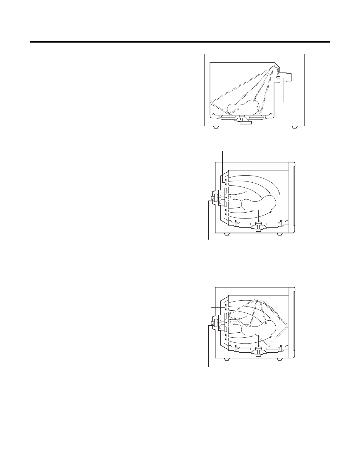
HOW THE MICROWAVE/
CONVECTION OVEN WORKS
MICROWAVE COOKING
Using microwave energy only, food is cooked quickly
without altering its color or shape. The food is evenly
cooked on a rotating turntable as the microwaves are
produced by the magnetron. Power Control can be
adjusted in 10 steps, enabling the various kinds of foods
to cook at most desirable cooking power for the best
results.
CONVECTION COOKING
This is a way of cooking with hot air from the convec-tion
heater on the back side of the unit. This method allows
food to be browned evenly without losing any of the
juices. Heated air is circulated in the oven by a fan to
enable the heating and cooking of food. Since hot air
remains in the oven as it circulates, cooking is very
efficient. The temperature inside the oven can be controlled according to the type of food being cooked.
COMBINATION COOKING
With microwave energy and hot air, this solid-state
control can cook alternately according to the cycles
programmed between microwave and hot air to pro-vide
efficient cooking fully utilizing the advantages of
two functions. Convection rack is also used in Combination Cooking.
Fig. 5
Magnetron
Convection Heater
Convection Rack
Circulation
Motor
Convection Heater
Convection Rack
Circulation
Motor
– 11 –
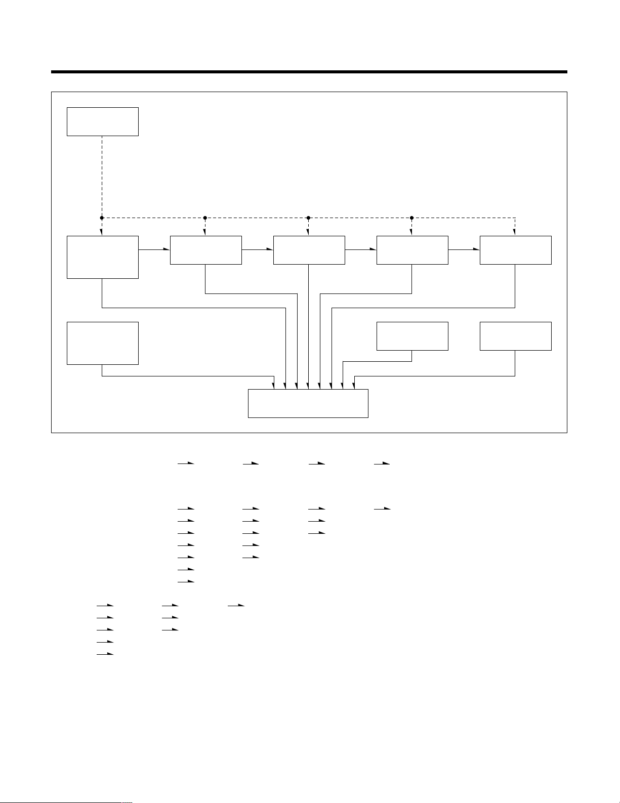
COOKING FLOW CHART
Cooking procedure have five sequential programs.
AUTO WEIGHT DEFROST STAGE 1 STAGE 2 STAGE 3 HOLD WARM
Cooking program can be partially and independently selected.
Example:
AUTO WEIGHT DEFROST STAGE 1 STAGE 2 STAGE 3 HOLD WARM
AUTO WEIGHT DEFROST STAGE 1 STAGE 2 STAGE 3
AUTO WEIGHT DEFROST STAGE 1 STAGE 2 HOLD WARM
AUTO WEIGHT DEFROST STAGE 1 STAGE 2
AUTO WEIGHT DEFROST STAGE 1 HOLD WARM
AUTO WEIGHT DEFROST STAGE 1
AUTO WEIGHT DEFROST HOLD WARM
AUTO WEIGHT DEFROST
STAGE 1 STAGE 2 STAGE 3 HOLD WARM
STAGE 1 STAGE 2 STAGE 3
STAGE 1 STAGE 2 HOLD WARM
STAGE 1 STAGE 2
STAGE 1 HOLD WARM
STAGE 1
HOLD WARM
AUTO WEIGHT COMBINATION
REHEAT
POPCORN
START
REHEAT
AUTO
WEIGHT
DEFROST
AUTO
WEIGHT
COMBINATION
STAGE 1 STAGE 3
HOLD
WARM
STAGE 2
CLOCK
POPCORN

– 12 –
OPERATING INSTRUCTIONS
TO SET THE TIME OF DAY
1. When the oven is plugged in, the display window will
show zero( :0)
2. Touch CLOCK.
3. Touch numbers for correct time of day.
4. Touch CLOCK again.
NOTE:
• If your oven does not operate properly, unplug the
oven from the 120-volt household outlet and then
plug it back in.
• To reset the time of day in the display window, touch
CLOCK again.
The colon will disappear. Enter the correct time of day
by following the above procedure.
• Oven will operate even though the TIME OF DAY is
not set.
• If the TIME OF DAY is not set, nothing will show in
the display window when STOP/CLEAR is touched.
• The TIME OF DAY can be set only from 1 : 00 to 12
: 59. At invalid setting, “E” will appear in the display
window with two short and one long beep sounds.
Only STOP/CLEAR can be operated while an error
condition exists.
• If you accidentally touch more than 4 numbers, the
last 4 numbers you have touched will appear in the
display window.
• If a momentary power failure occurs, the clock display
returns to zero ( : 0). If this occurs, please reset the
clock.
• If STOP/CLEAR is touched or door is opened after
cooking, the TIME OF DAY will appear in the display
window.
• If you don't set the time of day, the display counts
up per minute.
REGULAR TIMER
1. Touch MICRO TIME.
2. Touch numbers for desired time.
3. Touch MICRO POWER.
4. Touch “0”
5. Touch START.
“MICRO TIME” COOKING
1. Touch MICRO TIME.
2. Touch numbers for desired cooking time.
3. Touch MICRO POWER.
4. Touch number for desired cooking power.
5. Touch START.
“CONVECTION” COOKING
To Preheat
1. Touch CONVECTION.
2. Touch number for desired preheating temperature.
3. Touch START.
NOTE:
• After oven temperature reached the selected
temperature, the oven will automatically begin to hold
operation at the preheat temperature for 30 minutes.
To Cook
1. Touch CONVECTION.
2. Touch number for desired oven temperature.
3. Touch numbers for desired cooking time.
4. Touch START.
NOTE:
• Convection cooking temperatures range from 225°F
to 450°F.
• When oven doesn't reach selected temperature, oven
temperature will appear in the display window.
Current temperature of oven will be displayed in rising
5°F increments. If oven temperature is lower than
200°F, the display window will show "LO F" until
oven temperature reaches 200°F.

– 13 –
“COMBINATION” COOKING
1. Touch COMBINATION HIGH or LOW.
2. Touch numbers for desired cooking time.
3. Touch START.
NOTE:
• Output is fixed as follows.
“AUTOMATIC DEFROST BY WEIGHT”
1. Touch MEAT, POULTRY or FISH of AUTO WEIGHT
DEFROST.
2. Touch numbers for desired weight.
3. Touch START.
NOTE:
• If you input over the acceptable weight, "E" will show
in the display window. It means error and the oven
does not operate.
• When five short beeps sound during Auto Weight
Defrost, please turn over foods.
• Each category can defrost food with the weight of the
defrosting food input. The cooking power will
automatically be fixed in proportion to the time.
Categories for Auto Weight Defrost and the maximum
weights are 9.9 lbs.
“AUTOMATIC COMBINATION”
COOKING
1. Touch AUTO COOK.
2. Touch number for desired category.
3. Touch numbers for desired cooking weight.
4. Touch START.
NOTE:
• If you input over the acceptable weight, "E" will show
in the display window. It means error and the oven
does not operate.
• When five short beeps sound during cooking, please
turn over foods.
• Don't cook with plugging in the temperature probe.
• If you touch Auto Weight Combination Cook key, the
cooking data input already in each stage is cancelled.
• If you are going to reprogram a certain cooking
function after programming Auto Weight Combination
data, STOP/CLEAR must always be touched before.
• Weight can be programmed in pounds and tenths of
a pound. Categories for Auto Weight Combination
Cooking and the maximum weights are 5.9 lbs.
“REHEAT”
1. Touch REHEAT.
2. Touch REHEAT repeatedly for desired category of
Reheat. (Touch 1. or 2)
3. Touch START.
NOTE:
• If you touch Reheat key, the cooking data input
already in each stage is cancelled.
• If you reprogram a certain cooking function after
programming Reheat data, STOP/CLEAR must
always be touched before.
“HOLD WARM”
1. Touch HOLD WARM.
2. Touch START.
NOTE:
• The time of HOLD WARM is 60 minutes.
• With temperature probe foods will be held at
120°F.
• Take care that the temperature probe is not removed
from foods.
MICROWAVE
COOKING TIME
COMBI-HIGH
COMBI-LOW
8 Sec
8 Sec
14 Sec (375°F)
14 Sec (350°F)
CONVECTION
COOKING TIME

– 14 –
“POPCORN”
1. Put a micro-proof rack on the turntable.
2. Touch POPCORN.
3. Touch START.
NOTE:
• If additional time is required, micro HI power in
increments of 20 sec.
• Elevate popcorn packages on a micro-proof rack.
• Do not leave oven unattended while popping corn.
• This feature can only be used for popping
packaged.
CHILD LOCK
To Set Child Lock
1. Touch “0” more than 2 seconds.
NOTE:
• When Child Lock is selected STOP/CLEAR must
always be touched before selection.
• At this time, the oven will operate normally but Micro
Power and Heater Power will be zero and cooking
can not take place.
• At this time, if you start to cook “L” will appear in the
display window for 1 sec at first.
.
To Cancel Child Lock
1. Touch “0” more than 2 seconds.
NOTE:
• When you cancel Child Lock, STOP/CLEAR must
always be touched before selection.
MULTI-STAGE COOKING
Let’s start to cook with a first stage 4 minutes at the
cooking power HI followed by a second stage of 10
minutes at cooking power 60.
1. Touch MICRO TIME.
2. Touch “4”, “0” and “0” in sequence.
3. Touch MICRO TIME.
4. Touch “1”, “0”, “0” and “0” in sequence.
5. Touch MICRO POWER.
6. Touch “6”.
7. Touch START.
NOTE:
• There are three memory stages.
– 15 –
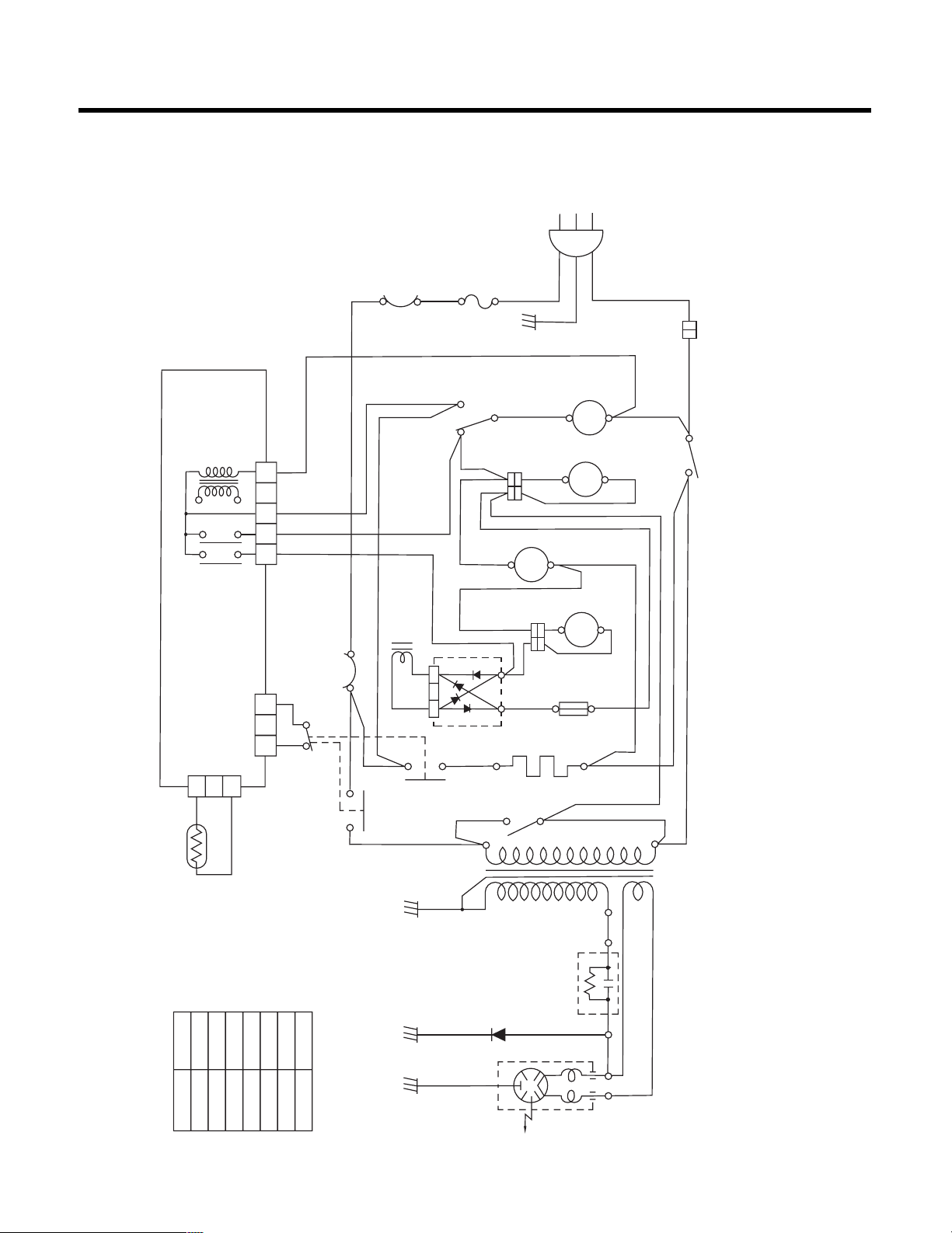
SCHEMATIC DIAGRAM
SYSTEM 1: STAND-BY CONDITION
Set up: Door is opened. Oven power cord is plugged into standard 120 volt ground outlet.
Normal operation
• Oven light turns on.
POWER
T
R
ANS
CN 1
1 2 3 4 5
WH B L R D YL
REL A Y 3
REL A Y 4
P. C.B.
1 2 3
THERMOSTAT
( M AGNE TR ON )
SOLENOID
WH
WH
WH
WH
WH
RD
RD
RD
RD
RD
RD RD
YL
YL
YL
RD
RD
RD
RD
OVEN
LAMP
SWITCH
NC
YL
NO
COM
BL
WH
WH
WH
WH
AC 120V
60Hz
THERMOSTAT
(OVEN)
FUSE
GN
OVEN LAMP
O. L
TURNTABLE MOTOR
T. T. M
FAN MOTOR
F.M.
C.M.
CIRCULATION MOTOR
RECTIFIRE FU SE
CONVECTION HEA TER
REL AY 2
MONI TOR SWITCH
REL A Y1
NOTE: 1. DOOR IS CLOSED.
2. COOK OFF.
3.CIRCUIT BE SUB JECT TO
CH A NGE WITHOU T NO TICE.
SYM B OL COLOR
WH WHI TE
BK BL A CK
BL BL UE
RD RED
YL YEL L OW
PK PINK
BN BROWN
HIGH VOL TAGE
DIODE
MAGNETRON
HIGH VOL TAGE
HIGH VOL TAGE
CAPACITOR
TRA N SFORM ER
1 2 3
SECONDARY
SWITCH
WH
WH
THERMI S TOR
PRIMAR Y
SWITCH
Fig. 6
– 16 –
SYSTEM 2: MICROWAVE COOKING CONDITION
Set up: Door is closed. START is touched.
Normal operation
• Oven light turns on.
• Turntable operates.
• Fan motor operates.
POWER
T
R
ANS
CN 1
1 2 3 4 5
WH B L R D YL
REL A Y 3
REL A Y 4
P. C.B.
1 2 3
THERMOSTAT
( M AGNE TR ON )
SOLENOID
WH
WH
WH
WH
WH
RD
RD
RD
RD
RD
RD RD
YL
YL
YL
RD
RD
RD
RD
OVEN
LAMP
SWITCH
NC
YL
NO
COM
BL
WH
WH
WH
WH
AC 120V
60Hz
THERMOSTAT
(OVEN)
FUSE
GN
OVEN LAMP
O. L
TURNTABLE MOTOR
T. T. M
FAN MOTOR
F.M.
C.M.
CIRCULATION MOTOR
RECTIFIRE FU SE
CONVECTION HEA TER
REL AY 2
MONI TOR SWITCH
REL A Y1
NOTE: 1. DOOR IS CL OSED.
2. COOK OFF.
3.CIRCUIT BE SUB JECT TO
CH A NGE WITHOU T NO TICE.
SYM B OL COLOR
WH WHI TE
BK BL A CK
BL BL UE
RD RED
YL YEL L OW
PK PINK
BN BROWN
HIGH VOL TAGE
DIODE
MAGNETRON
HIGH VOL TAGE
HIGH VOL TAGE
CAPACITOR
TRA N SFORM ER
1 2 3
SECONDARY
SWITCH
WH
WH
THERMI S TOR
PRIMAR Y
SWITCH
Fig. 7
– 17 –
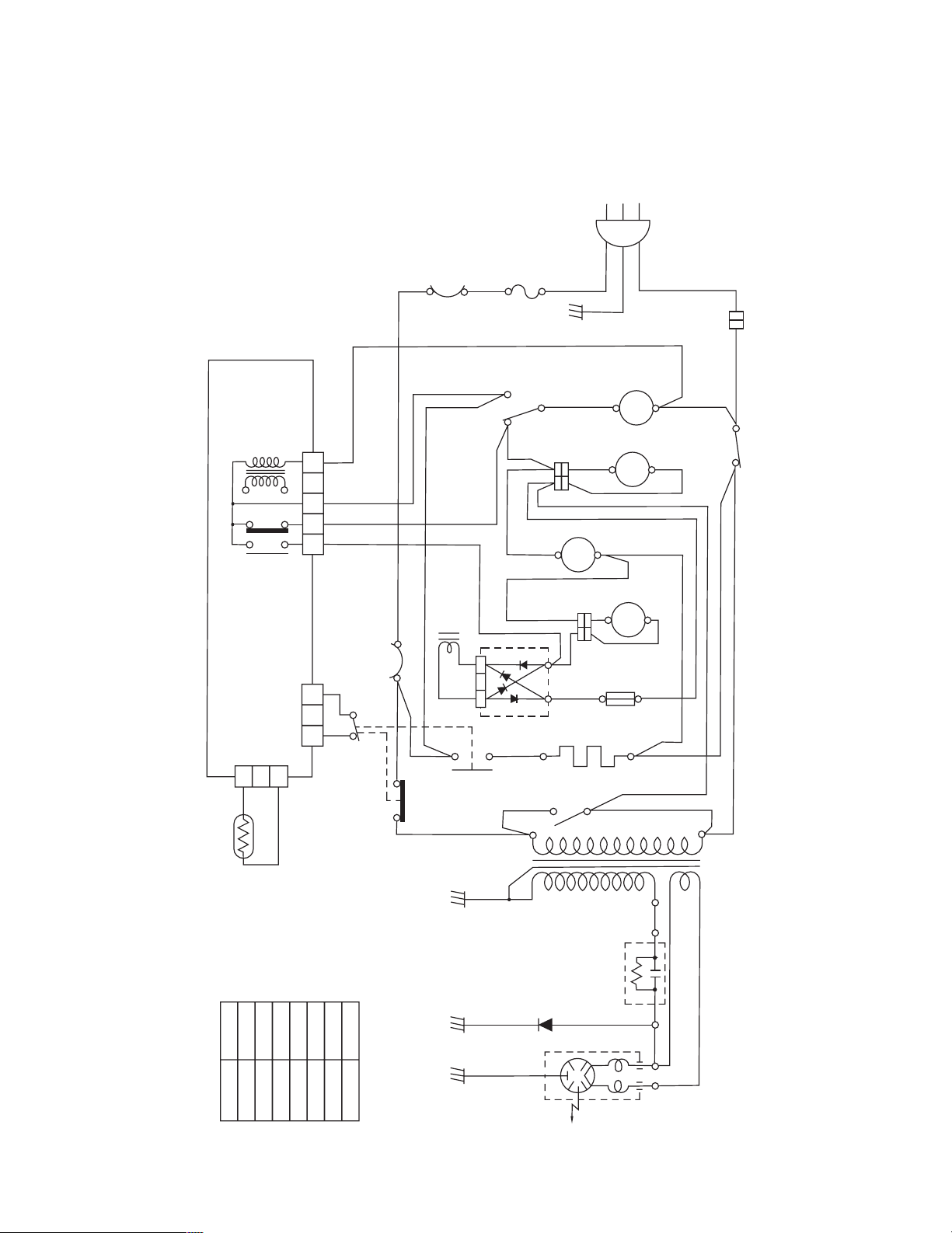
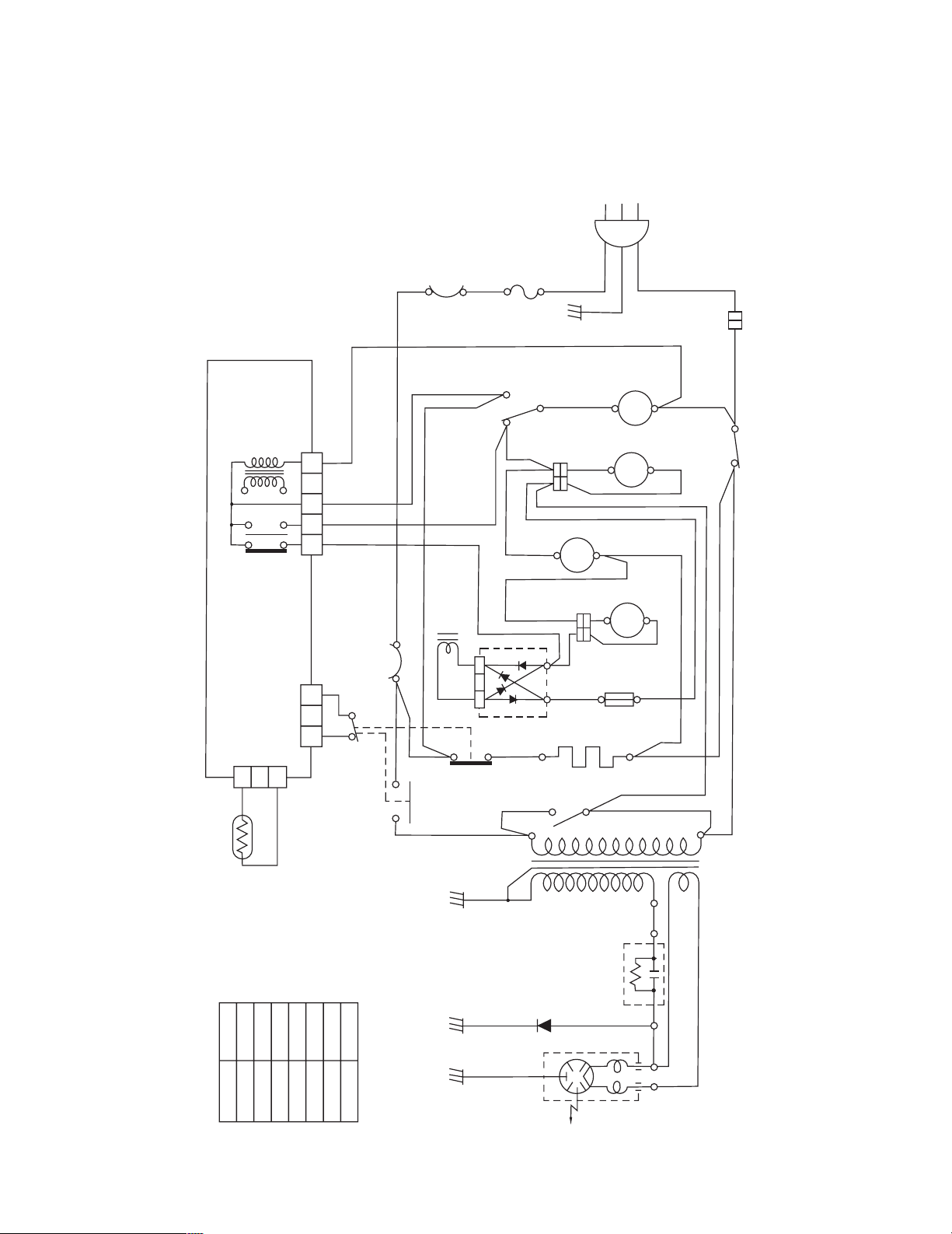
SYSTEM 3: CONVECTION COOKING CONDITION
Set up: Door is closed. START is touched.
Normal operation
• Oven light turns on.
• Turntable operates.
• Fan motor and circulation motor operate.
POWER
T
R
ANS
CN 1
1 2 3 4 5
WH B L R D YL
REL A Y 3
REL A Y 4
P. C.B.
1 2 3
THERMOSTAT
( M AGNE TR ON )
SOLENOID
WH
WH
WH
WH
WH
RD
RD
RD
RD
RD
RD RD
YL
YL
YL
RD
RD
RD
RD
OVEN
LAMP
SWITCH
NC
YL
NO
COM
BL
WH
WH
WH
WH
AC 120V
60Hz
THERMOSTAT
(OVEN)
FUSE
GN
OVEN LAMP
O. L
TURNTABLE MOTOR
T. T. M
FAN MOTOR
F.M.
C.M.
CIRCULATION MOTOR
RECTIFIRE FU SE
CONVECTION HEA TER
REL AY 2
MONI TOR SWITCH
REL A Y1
NOTE: 1.DOOR IS CLOSED.
2. COOK OFF.
3.CIRCUIT BE SUB JECT TO
CH A NGE WITHOU T NO TICE.
SYM B OL COLOR
WH WHI TE
BK BL A CK
BL BL UE
RD RED
YL YEL L OW
PK PINK
BN BROWN
HIGH VOL TAGE
DIODE
MAGNETRON
HIGH VOL TAGE
HIGH VOL TAGE
CAPACITOR
TRA N SFORM ER
1 2 3
SECONDARY
SWITCH
WH
WH
THERMI S TOR
PRIMAR Y
SWITCH
Fig. 8
 Loading...