

Page 1
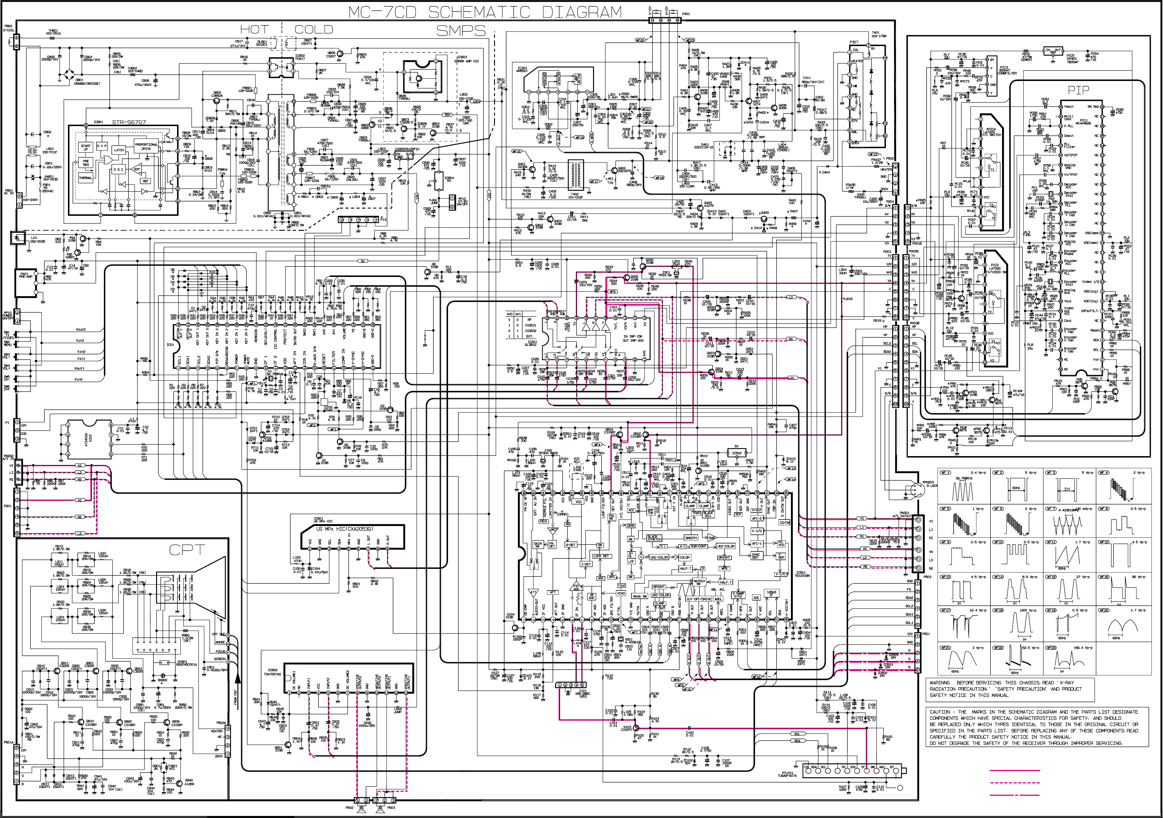
VIDEO
AUDIO
CHROMA
Page 2
- 1 -
ADJUSTMENT INSTRUCTION
These instructions are applied to only MC-7CA chassis.
Notes
1.Because this is not a hot chassis, it is not necessary to use
an isolation transformer.
However, the use of isolation transformer will help protect test
instrument.
2.Adjustment must be done in the correct order.
3.Supply 100~240V A.C./50~60Hz.
4.The receiver must be operated for about 20 minutes proir to
the adjustment.
CONTENTS
1. Stereo separation Adjustment
2. VCO Adjustment
3. AGC voltage Adjustment
4. Screen voltage Adjustment
5. White Balance Adjustment
6. FOCUS Adjustment
7. Sub-Bright Adjustment
8. Deflection Setting Data Adjustment
9. H-Size & SIDE PIN CUSHION Adjustment
1. Stereo separation Adjustment
1-1. Preparation
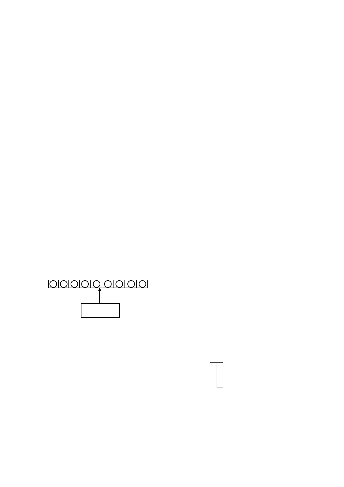
(1) Connect the measuring equipment to the TV as shown in Fig. 1.
(2) Open R601 and R602 to disconnect RF Audio signal.
(3) Press MENU button on the TV set and MENU button on
the Remote control at the same time to get into Adjustment
mode.
1-2. ATT input level adjustment
(1) Input 100Hz, 245mVrms(693mVp-p) signal to pin5 of IC601.
(2) Connect the Oscilloscope to pin 7 of IC601.
(3) Select ATT with CHANNEL button and adjust with VOLUME
button until the voltage of pin 7 is 1.38Vp-p(490mVrms).
(ATT : 0~15)
1-3. Stereo(ST) & SAP VCO Adjustment
(1) Disconnect the Modulator and connect the frequency counter
to pin 9 of IC601.
(2) Select ST VCO with CHANNEL button and adjust with
VOLUME button until the frequency is 62.936
!0.1KHz.
(VCO : 0~63)
1-4. Filter Adjustment
(1) Input 9.4KHz, 600mVrms(1.697Vp-p) signal to pin 5 of IC601.
(2) Connect the Oscilloscope to pin 9 of IC601.
(3) Select FILTER with CHANNEL button and adjust with
VOLUME button until STATUS becomes the center of 1.
(FILTER : 0~63)
1-5. Separation Adjustment
(1) Input ST L-only 300Hz signal 30% Modulation of Modulator to
pin 5 of IC601.
(2) Connect the Oscilloscope to pin 9 of IC601.
(3) Select WIDEBAND with CHANNEL button and adjust with
VOLUME button until the waveform is minimum.
(WIDEBAND : 0~63)
(4) Change the frequency of Modulator to 3KHz.
(5) Select SPECTRAL with CHANNEL button and adjust with
VOLUME button until the waveform is minimum.
(SPECTRAL : 0~63)
2. VCO Adjustment
(1) Connect the antenna cable.
(2) Press MENU button on the TV set and MENU button on
the Remote control at the same time to get into Adjustment
mode.
Press channel Up/Down buttons to select an adjustment.
Press volume Up/Down buttons to vary the data.
(3) Select VP 0(AUTOPIF) mode by pressing channel
Up/Down button.
OSD will be displayed in Orange.
(4) Adjust VP 0(AUTOPIF) data by pressing volume Up/Down
button.
OSD(AUTOPIF) color is changed to Green.
3. AGC voltage Adjustment
3-1. Preparation
Connect the DMM to J101 on Main PCB.
3-2. Adjustment
(1) Select VP 1(RFAGC) with CHANNEL button in Adjustment
mode.
(2) Adjust with VOLUME button until the voltage is 4.6!0.1V.
4. Screen Voltage Adjustment
(1) Input the Digital Pattern to TV set.
(2) Press the APC button on the Remote Control for APC ON.
APC ON CONTRAST : 100
BRIGHT : 50
COLOR : 50
TINT : 0
SHARPNESS : 60
(3) Make the screen has the horizontal line by pressing SVC
button of service Remote control.
(4) Turn the screen control clockwise until the Horizontal line is
visible and turn it counterclockwise until the Horizontal line
is faintly visible.
MULTIPLEX
MODULATOR
IC601
Vcc GND SCL SDA MPX
in
GND Lo GND Ro
12 3 4 5 6 7 8 9
<Figure 1>
Page 3

5. White Balance Adjustment
(1) Press MENU button on the TV set and MENU button on
the Remote control at the same time to get into Adjustment
mode.
(2) Press CH Up/Down to select adjustment item.
(3) Press VOL Up/Down to change Data.
(4) Adjustment
1. Adjust Contrast and Brightness until the highlight area of
signal is 35Ft-1.
2. Select GDRIVE (VP 10) and BDRIVE (VP 11) and adjust
to get the Highlight data.
3. Adjust Contrast and Brightness until the highlight area of
signal is 4.5Ft-1.
4. Select G-CUT (VP 8) and B-CUT (VP 9) and adjust to
get the Low light data .
5. Repeat adjustment 1 ~4 above to get both Low and High
light data.
6. Check the result of adjustment using White Balance
Meter
HIGH LIGHT : X=0.282!0.008, Y=0.288!0.008
(10,000!1000
cK)
LOW LIGHT : X=0.282!0.008, Y=0.288!0.008
(10,000!1000cK)
6. FOCUS Adjustment
(1) Input the Digital Pattern to TV set.
(2) Press the APC button on the Remote Control for APC ON
condition.
APC ON CONTRAST : 100
BRIGHT : 50
COLOR : 50
TINT : 0
SHARPNESS : 60
(3) Adjust the FOCUS control on the FBT to obtain a sharp and
clear picture.
7. Sub-Bright Adjustment
(1) Input the Mono scope signal as Fig. 2.
(2) Set the screen for Adjustment Mode by Remote Control.
(3) Select Sub-Bright and adjust until A part is distinguishable.
8. Deflection setting Data Adjustment
(1) Set the TV set in the Power off condition(stand-by).
(2) Press MENU button on the TV set and MENU button on
the Remote control at the same time to get into Adjustment
mode.
(3) Press CH Up/Down to select adjustment item.
(4) Press VOL Up/Down to change Data.
8-1. Horizontal Position(HPOS)
Select VP 2(HPOS) and adjust until left and right side of
screen is equal.
8-2. Vertical Position(VPOS)
Select VP 3(VPOS) and adjust until the mechanical center of
CPT and the center of screen coincides.
8-3. Vertical Size(VSIZE)
Select VP 4(VSIZE) and the center circle of Digital Pattern
coincides with the outer frame of screen.
8-4. Vertical Linearity(VLIN)
Select VP 5(VLIN) and adjust until the upper and lower side of
screen is equal.
8-5. Vertical Correction(VSCORR)
Select VP 6(VSCORR) and adjust until the circle becomes
perfect.
9. H-Size & SIDE PIN CUSHION Adjustment
(1) Input the standard signal.
(2) Turn the adjustment volume VR400 of the H-center and
adjust the right and left horizontal mark to touch samely with
the standard of the right and left frame.
(3) Input CROSS-HATCH PATTERN.
(4) Set SIDE PIN CUSHION (VR401) to the mechanical center.
(5) Turn the SIDE PIN CUSHION (VR401) so that outer-shell
vertical line spread to linearly.
- 2 -
0 1 2 3 4 5 6 7 8 9
Gray Scale
Color Bar
<Figure2>
Page 4

- 3 -
PURITY & CONVERGENCE ADJUSTMENT
Caution:
Convergence and Purity have been factory aligned. Do not
attempt to tamper with these alignments.
However, the effects of adjacent receiver components, or
replacement of picture tube or deflection yoke may require the
need to readjust purity any convergence.
7 Purity Adjustment
This procedure DOES NOT apply to bonded yoke and picture
tube assemblies.
The instrument should be at room temperature (60 degrees F or
above) for six (6) hours and be operating at low beam current
(dark background) for approximately 20 to 30 minutes before
performing purity adjustments.
CAUTION: Do not remove any trim magnets that may be
attached to the bell of the picture tube.
1. Remove the AC power and disconnect the internal
degaussing coil.
2. Remove the yoke from the neck of the picture tube.
3. If the yoke has the tape version beam bender, remove it and
replace it with a adjustable type beam bender (follow the
instructions provided with the new beam bender)
4. Replace the yoke on the picture tube neck, temporarily
remove the three (3) rubber wedges from the bell of the
picture tube and then slide the yoke completely forward.
5. Reconnect the internal degaussing coil.
6. Position the beam bender locking rings at the 9 o'clock
position and the other three pairs of tabs (2,4 and 6 pole
magnets) at the 12 o'clock position.
7. Perform the following steps, in the order given, to prepare the
receiver for the purity adjustment procedure.
a. Face the receiver in the "magnetic north" direction.
b. Externally degauss the receiver screen with the television
power turned off.
c. Turn the television on for approximately 10 seconds to
perform internal degaussing and then turn the TV off.
d. Unplug the internal degaussing coil. This allows the
thermistor to cool down while you are performing the purity
adjustment. DO NOT MOVE THE RECEIVER FROM ITS
"MAGNETIC NORTH" POSITION.
e. Turn the receiver on and obtain a red raster by increasing
the red bias control (CW) and decreasing the bias controls
for the remaining two colors (CCW).
f. Attach two round magnets on the picture tube screen at 3
o'clock and 9 o'clock positions, approximately one (1) inch
from the edge of the mask (use double-sided tape).
DEFLECTION YOKE
PURITY &CONVERGENCE
MAGNET ASSEMBLY
RUBBER
WEDGES
GLASS CLOTH TAPE
PURITY MAGNET
6-POLE
4-POLE
4-POLE
MAGNET
CONVERGENCE MAGNET ASSEMBLY
6-POLE
MAGNES
PURITY MAGNET(2-POLE)
X-AXIS YOKE
POSITIONING
(L/R PURITY)
6-POLE
MAGNETS
CONVERGENCE MAGNET ASSEMBLY
Page 5

- 4 -
8. Referring to above, perform the following two steps:
a. Adjust the yoke Z-axis to obtain equal blue circles.
b. Adjust the appropriate beam bender tabs to obtain correct
purity (four equal circles).
9. After correct purity is set, tighten the yoke clamp screw and
remove the two screen magnets.
10. Remove the AC power and rotate the receiver 180 degrees
(facing "magnetic south").
11. Reconnect the internal degaussing coil.
12. Turn the receiver on for 10 seconds (make sure the receiver
came on) to perform internal degaussing, and then turn the
receiver off.
13. Unplug the internal degaussing coil.
14. Turn on the receiver and check the purity by holding one (1)
round magnet at the 3 o'clock and a second round magnet at
9 o'clock position. If purity is not satisfactory, repeat steps 8
through 14.
15. Turn off the receiver and reconnect the internal degaussing
coil.
7 Convergence Adjustment
Caution: This procedure DOES NOT apply to bonded yoke and
picture tube assemblies.
Do not use screen magnets during this adjustment
procedure. Use of screen magnets will cause an
incorrect display.
1. Remove AC power and disconnect the internal degaussing
coil.
2. Apply AC Power and set the brightness to the Picture Reset
condition. Set the Color control to minimum.
3. Apply 8V to the pin42 of IC501.
4. Adjust the Red, Green and Blue Bias controls to get a dim
white line.
5. Remove the AC power and 8V from the pin42 of IC501.
6. Reconnect the internal degaussing coil and apply AC power.
7. Turn the receiver on for 10 seconds to perform internal
degaussing and then turn the receiver off again.
8. Unplug the internal degaussing-coil.
9. Turn on the receiver, connect a signal generator to the VHF
antenna terminal and apply a crosshatch signal.
Caution: During the convergence adjustment procedure, be
very careful not to disturb the purity adjustment tabs
are accidentally move, purity should be confirmed
before proceeding with the convergence adjustments.
Note:
Make sure the focus is set correctly on this instrument
before proceeding with the following adjustment.
10. Converge the red and blue vertical lines to the green vertical
line at the center of the screen by performing the following
steps (below TABLE).
a. Carefully rotate both tabs of the 4-pole ring magnet
simultaneously in opposite directions from the 12 o'clock
position to converge the red and blue vertical lines.
b. Carefully rotate both tabs of the 6-pole ring magnet
simultaneously in opposite directions form the 12 o'clock
position to converge the red and blue (now purple)
vertical lines with the green vertical line.
11. Converge the red and blue horizontal with the green line at
the center of the screen by performing the following steps.
(below TABLE)
a. Carefully rotate both tabs of the 4-pole ring magnet
simultaneously in the same direction (keep the spacing
between the two tabs the same) to converge the red and
blue horizontal lines.
b. Carefully rotate both tabs of the 6-pole ring magnet
simultaneously in same direction (keep the spacing
between the two tabs the same) to converge the red and
blue (now purple) horizontal lines with the green
horizontal line.
c. Secure the tabs previsouly adjusted by locking them in
place with the locking tabs on the beam bender.
MAGNETS
RED RED
1.ADJUST YOKE Z-AXIS FIRST
TO GET EQUAL BLUE
COLOR CIRCLES
2 .ADJUST BEAM BENDER 2 POLE
MAGNET TO GET FOUR EQUAL
COLOR CIRCLES
Page 6

- 5 -
RING
PAIRS
4
POLE
ROTATION DIRECTION
OF BOTH TABS
OPPOSITE
SAME
OPPOSITE
SAME
MOVEMENT OF RED
AND BLUE BEAMS
B B
RR
OR
OR
B R B R
OR
B
R
B
R
B R
OR
B
R
6
POLE
12. While watching the 6 o'clock positions on the screen, rock the
front of the yoke in a vertical (up/down) direction to converge
the red and blue vertical lines. (Fig upper left)
13. Temporarily place a rubber wedge at the 12 o'clock position
to hold the vertical position or the yoke.
14.
Check the 3 o'clock and 9 o'clock areas to confirm that the red
and blue horizontal lines are converged.
If the lines are not converged, slightly offset the vertical tilt of the
yoke (move the rubber wedge if necessary) to equally balance the
convergence error of the horizontal lines at 3 o'clock and 9 o'clock
and the vertical lines at 6 o'clock and 12 o'clock.
15. Place a 1.5 inch piece of glass tape over the rubber foot at
the rear of the 12 o'clock wedge.
16. While watching the 6 o'clock and 12 o'clock areas of the
screen, rock the front of the yoke in the horizontal (left to
right) motion to converge the red and blue horizontal lines.
(Fig. upper right)
17. Temporarily place a rubber wedge at the 5 o'clock and 7
o'clock positions to hold the horizontal position of the yoke.
18. Check the 3 o'clock and 9 o'clock areas to confirm that the
red and blue vertical lines are converged. If the lines are not
converged, slightly offset the horizontal tilt of the yoke (move
the temporary rubber wedges if necessary) to equally
balance the convergence error of the horizontal lines at 6
o'clock and 12 o'clock and the vertical lines at 3 o'clock and 9
o'clock.
19. Using a round magnet confirm purity at the center, right and
left sides and corners. See Purity Adjustment Procedure.
20. Reconfirm convergence and apply a 1.5 inch piece of glass
tape over the rubber foot at the rear of the 5 o'clock and the 7
o'clock wedges.
RED
BLUE
RED BLUE
BLUE
RED
GREEN
GREEN
BLUE RED
GREEN
GREEN
ADJUSTMENT
VIEWING
AREA
UP/DOWN ROCKING OF THE YOKE
CAUSES OPPOSITE ROTATION OF RED
AND BLUE RASTERS
ADJUSTMENT
VIEWING
AREA
RED
RED
GREEN
TV
SCREEN
LEET/RIGHT ROCKING OF THE YOKE
CAUSES OPPOSITE SIZE CHANGE OF
THE RED AND BLUE RASTERS
UP/DOWN ROCKING OF THE YOKE
CAUSES OPPOSITE ROTATION OF RED
AND BLUE RASTERS
LEFT/RIGHT ROCKING OF THE YOKE
CAUSES OPPOSITE SIZE CHANGE OF THE
RED AND BLUE RASTERS
 Loading...