

LG M4224NCB32, M4224N-B32, M4224N User Manual

User's Guide
M4224N
M
ake sure to read the
Keep the User's Guide(CD) in an accessible place for future reference.
S
ee the label attached on the product and give the information to your dealer when you ask for
service.
Temporary noise is normal when powering ON or OFF this device.
WARNING -This is a class A product. In a domestic environment this product may cause radio
interference in which case the user may be required to take adequate measures.
Safety Precautions
Important
WARRANTY VOID
IF REMOVED
before using the product.
Warranty void if removed.
3850TAZ209Y
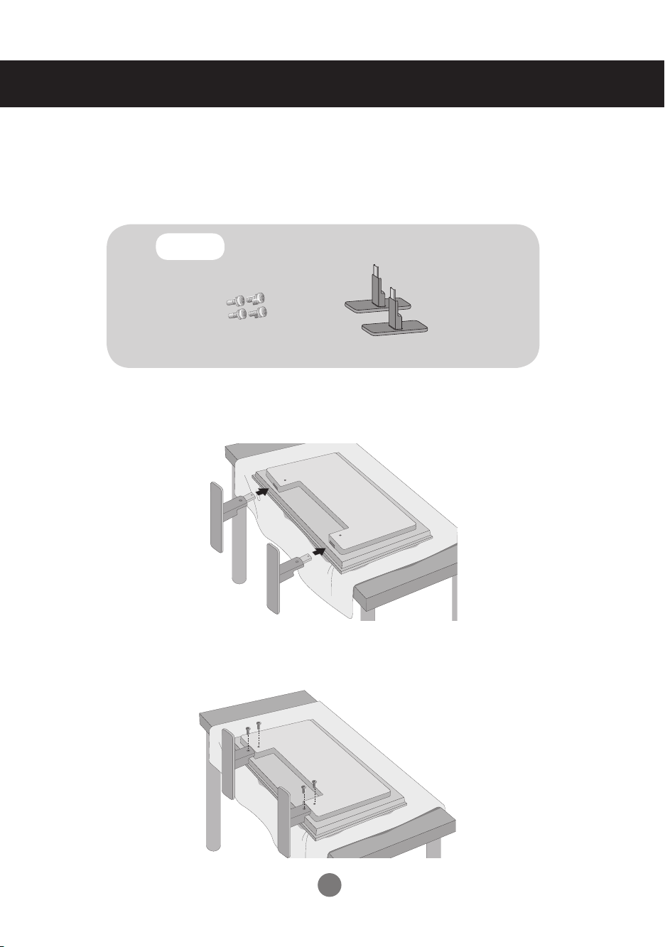
Connecting the stand
- Only on some models.
1.
Take the parts for the stand out of the box and assemble them as shown in the
picture.
Parts
2.
Place a soft cloth on the table and put the product with the screen facing downward. Connect the stand as shown in the following picture.
First, check if the following parts are all present.
Screws (4)
Stand (2)
3.
Use the screws to secure the stand on the rear side of the product as shown in
the diagram.
1
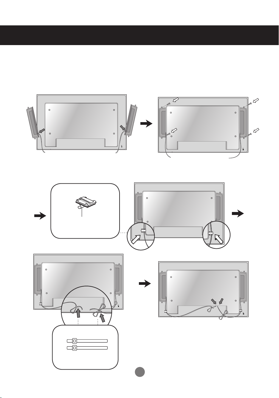
Connecting the Speakers
- Only on some models.
Mount the product onto the speaker by using a screw as shown in the following
connect the speaker cable.
After installing your speakers, use holders and cable ties to organize the speaker cables.
Cable holder
Remove the paper.
* This feature is not available in all model.
Cable tie
* This feature is not available in all model.
When the speaker is installed.
*Connect the input terminal with a proper color match.
2
Using the Remote Control
1 2 3
4 5 6
7 8
0
9
CTR.
PWR
*
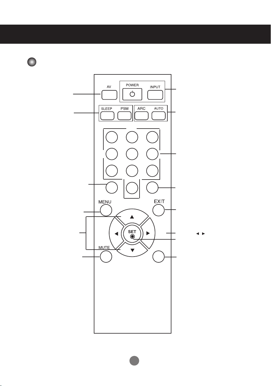
Name of the Remote Control Buttons
There is not a function
which is supported
There is not a function
which is supported
Turn on the power of the
(The CTR.PWR function
PC Control menu is off.)
▪ UP and Down buttons
Bring up and down direction
▪ CTR.PWR Button
PC built in the monitor
and then turn off.
operates only when the
▪ Menu Button
adjustment.
▪ Power On/Off Button
▪
Input Select Button
(See next page)
▪ ARC button
To select the image size
of the screen.
▪ Auto Button
Automatic adjustment
function (Operational for
the analog signal only)
There is not a function
which is supported
There is not a function
which is supported
▪ Exit Button
Volume Button
▪
▪ Check Button
▪ Mute button
There is not a function
which is supported
3
Using the Remote Control
1 2 3
4 5 6
7 8
0
9
CTR.
PWR
*
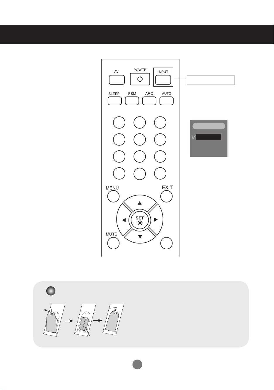
▪
Input Select Button
If you press the button once,
the following Input Signal
Window will appear. Select
the signal type you want
using the ▼▲ button.
INPUT
RGB
DVI
Inserting batteries into remote control.
1. Take out the battery cap.
2. Insert the batteries with correct polarity (+/-).
3. Close the battery cap.
▪ Dispose of used batteries in the recycle bin to prevent
environmental pollution.
AAA Type
4
Name and Function of the Parts
RGB IN
OUT
IN
RGB IN
RGB OUT
DVI IN
RS-232C
(CONTROL)
AUDIO
(RGB/DVI)
REMOTE
CONTROL IN
LAN
USB
USB
H/PHONE
OUT
MIC IN
SP/DIF
SERIAL PORT
RGB OUT
RGB OUT
OUT
IN
RGB IN
RGB OUT
DVI IN
RS-232C
(CONTROL)
AUDIO
(RGB/DVI)
REMOTE
CONTROL IN
LAN
USB
USB
H/PHONE
OUT
MIC IN
SP/DIF
SERIAL PORT
RGB OUT
* The product image in the user’s guide could be different from the actual image.
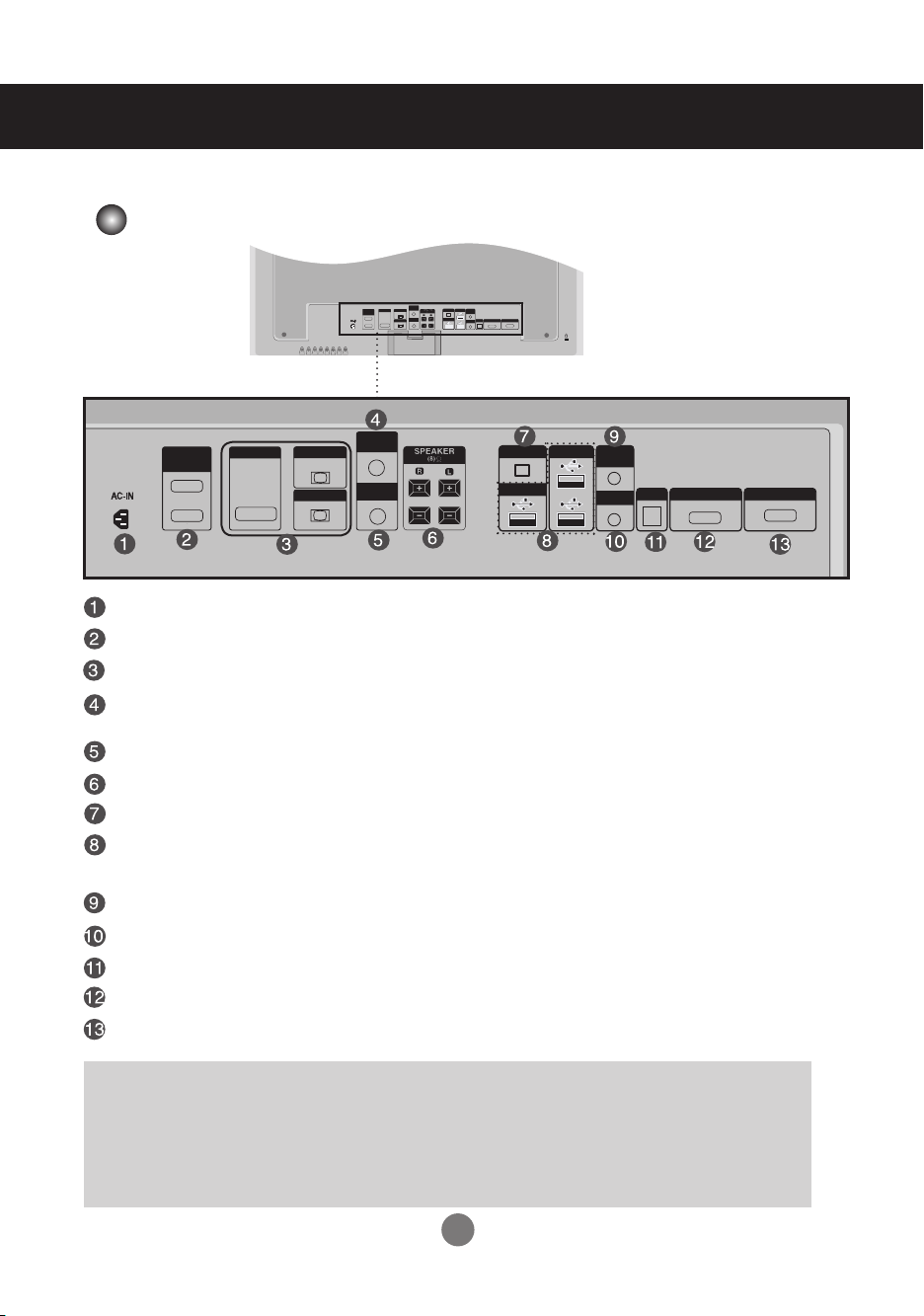
Rear View
Power Connector : Connect the power cord
RS-232C Serial Ports (IN, OUT)
RGB, DVI Ports (IN, OUT)
PC Sound Jack
: Connect the audio cable to the *LINE OUT jack of the PC sound card.
ired Remote Control Port
Speaker Ports
LAN Ports
USB Ports :
Program installation and operation can be done by using USB Memory, USB HardDisk, USB CD-ROM, Keyboard (Wired or wireless), Mouse (wired or wireless), etc.
Head Phone out Port
MIC IN Ports
Optical Sound out Ports
Serial Ports
RGB out Ports
*LINE OUT
A terminal used to connect to the speaker including a built-in amplifier (Amp). Make sure
that the connecting terminal of the PC sound card is checked before connecting. If the
Audio Out of PC sound card has only Speaker Out, reduce the PC volume.
If the Audio Out of the PC sound card supports both Speaker Out and Line Out, convert
to Line Out using the card jumper of the program (Refer to the Sound Card Manual).
5
Connecting to External Devices
OUT
IN
RGB IN
RGB OUT
DVI IN
RS-232C
(CONTROL)
AUDIO
(RGB/DVI)
REMOTE
CONTROL IN
LAN
USB
USB
H/PHONE
OUT
MIC IN
SP/DIF
SERIAL PORT
RGB OUT
OUT
IN
RGB IN
RGB OUT
DVI IN
RS-232C
(CONTROL)
AUDIO
(RGB/DVI)
REMOTE
CONTROL IN
AUTO/SET
SOURCE
SOURCE
MENU
INPUT
SET
INPUT
SOURCE
SET
AUTO/SET
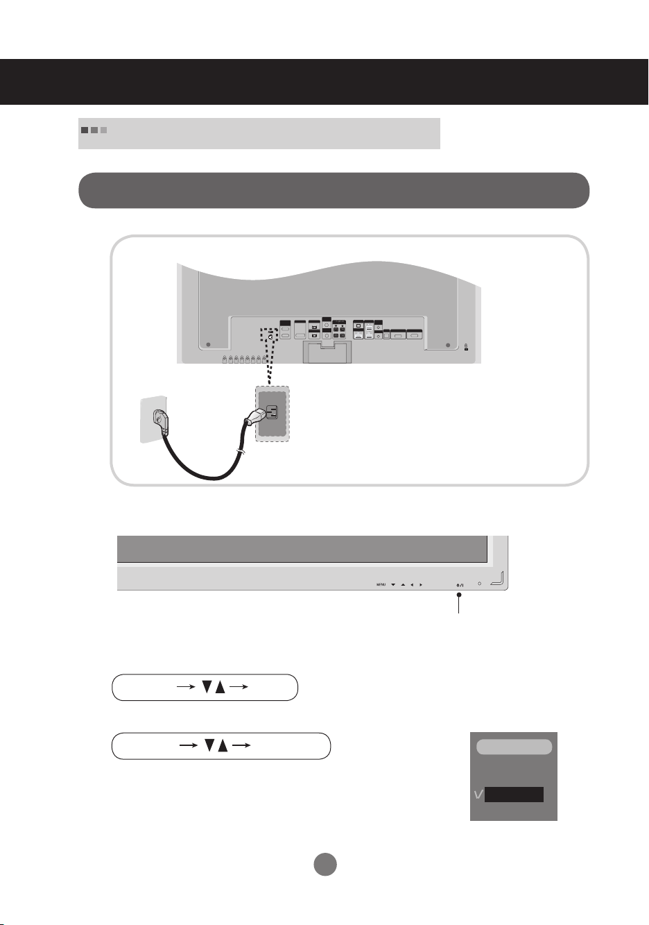
When Connecting to your Built in PC
When connecting with the DVI signal input
1.
Rear side of the product.
Connect the power cord.
2.
Turn on power by pressing the power button on the product.
Power button
3.
Select an input signal.
Press the INPUT button on the remote control to select the input signal.
Or, press the SOURCE button at the back side of the product.
▪ Select DVI :
DVI
Digital signal.
6
INPUT
RGB
DVI
Connecting to External Devices
AUTO/SET
SOURCE
SOURCE
MENU
RGB IN
OUT
IN
RGB IN
RGB OUT
DVI IN
RS-232C
(CONTROL)
AUDIO
(RGB/DVI)
REMOTE
CONTROL IN
LAN
USB
USB
H/PHONE
OUT
MIC IN
SP/DIF
SERIAL PORT
RGB OUT
RGB OUT
H/PHONE
OUT
RGB IN
AUDIO
(RGB/DVI)
REMOTE
CONTROL IN
OUT
IN
RGB IN
RGB OUT
DVI IN
RS-232C
(CONTROL)
AUDIO
(RGB/DVI)
REMOTE
CONTROL IN
LAN
USB
USB
H/PHONE
OUT
MIC IN
SP/DIF
SERIAL PORT
RGB OUT
OUT
IN
RGB IN
RGB OUT
DVI IN
RS-232C
(CONTROL)
AUDIO
(RGB/DVI)
REMOTE
CONTROL IN
LAN
USB
USB
H/PHONE
OUT
MIC IN
SP/DIF
SERIAL PORT
RGB OUT
RGB IN
OUT
IN
RGB IN
RGB OUT
DVI IN
RS-232C
(CONTROL)
AUDIO
(RGB/DVI)
REMOTE
CONTROL IN
LAN
USB
USB
H/PHONE
OUT
MIC IN
SP/DIF
SERIAL PORT
RGB OUT
OUT
IN
RGB IN
RGB OUT
DVI IN
RS-232C
(CONTROL)
AUDIO
(RGB/DVI)
REMOTE
CONTROL IN
LAN
USB
USB
H/PHONE
OUT
MIC IN
SP/DIF
SERIAL PORT
RGB OUT
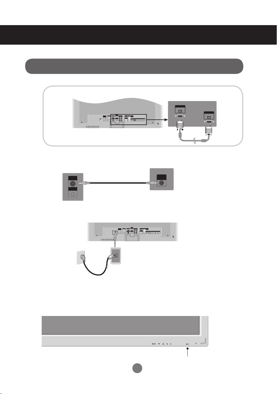
When connecting with the D-Sub signal input cable.
1.
2.
3.
Rear side of the product.
Rear side of the product.
Connect the Audio Cable
Rear side of the product.
Rear side of the product.
Connect the Power Cord
* User must use shielded signal interface cables (D-sub 15 pin cable, DVI cable) with ferrite cores to maintain standard compliance for the product.
Turn on power by pressing the power button on the product.
4.
7
Power button
Connecting to External Devices
INPUT
SET
INPUT
SOURCE
SET
AUTO/SET
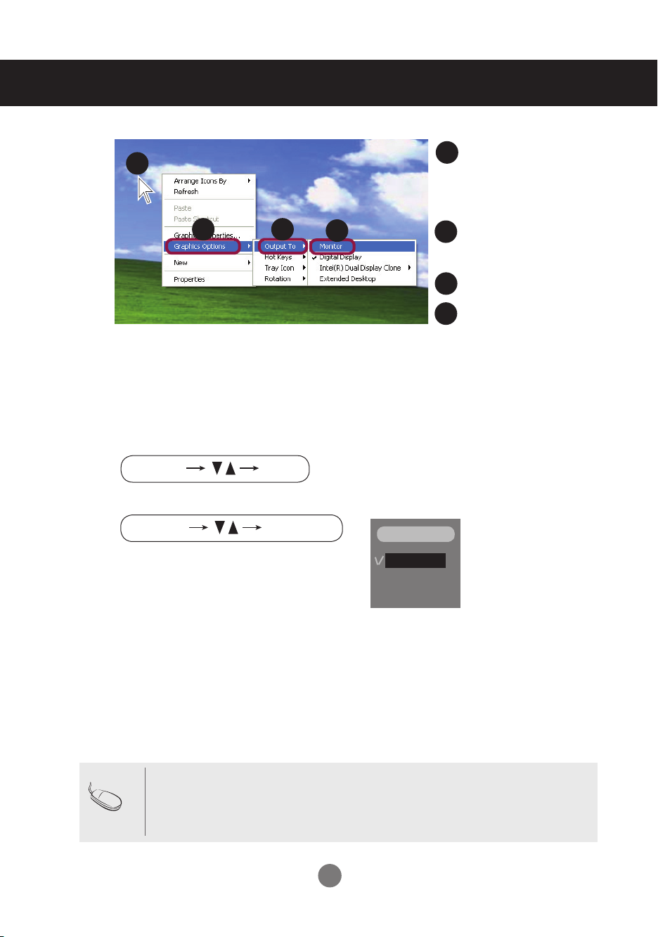
Move the mouse pointer
5.
6.
1
2
Select an input signal.
Press the INPUT button on the remote control to select the input signal.
Or, press the SOURCE button at the back side of the product.
3
4
1
to an empty area on the
Windows screen (with no
icons or task bars) and
click the right mouse button.
2
When the pop-up menu
appears, click the
‘Graphics Options' menu.
3
click the 'Output To' menu.
4
click the 'Monitor' menu.
When connecting with a D-Sub signal input cable.
▪ Select RGB : 15-pin
▪
Note
How to connect to two computers.
Connect the signal cables (DVI and D-Sub) to each computer.
Press the INPUT button in a remote control to select the computer to use.
▪
Directly connect to a grounded power outlet on the wall or a power bar with a ground wire.
D-Sub
analog signal.
INPUT
RGB
DVI
8
Connecting to External Devices
INPUT
SET
INPUT
SOURCE
SET
AUTO/SET
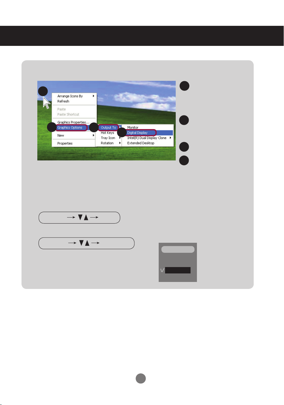
* In order to convert the RGB signal to the DVI signal
Move the mouse point-
1.
1
2
3
4
Select an input signal.
2.
Press the INPUT button on the remote control to select the input signal.
1
er to an empty area on
the Windows screen
(with no icons or task
bars) and click the right
mouse button.
2
When the pop-up menu
appears, click the
'Graphics Options' menu.
Click the 'Output To' menu.
3
Click the 'Digital Display'
4
menu.
Or, press the SOURCE button at the back side of the product.
INPUT
When connecting with a DVI signal input cable.
▪ Select DVI :
DVI
Digital signal.
9
RGB
DVI
Connecting to External Devices
OUT
IN
RGB IN
RGB OUT
DVI IN
RS-232C
(CONTROL)
AUDIO
(RGB/DVI)
REMOTE
CONTROL IN
LAN
USB
USB
H/PHONE
OUT
MIC IN
SP/DIF
SERIAL PORT
RGB OUT
RGB IN
OUT
IN
RGB IN
RGB OUT
DVI IN
RS-232C
(CONTROL)
AUDIO
(RGB/DVI)
REMOTE
CONTROL IN
LAN
USB
USB
H/PHONE
OUT
MIC IN
SP/DIF
SERIAL PORT
RGB OUT
RGB IN
OUT
IN
RGB IN
RGB OUT
DVI IN
RS-232C
(CONTROL)
AUDIO
(RGB/DVI)
REMOTE
CONTROL IN
LAN
USB
USB
H/PHONE
OUT
MIC IN
SP/DIF
SERIAL PORT
RGB OUT
RGB OUT
DVI IN
RGB IN
OUT
IN
RGB IN
RGB OUT
DVI IN
RS-232C
(CONTROL)
AUDIO
(RGB/DVI)
REMOTE
CONTROL IN
LAN
USB
USB
H/PHONE
OUT
MIC IN
SP/DIF
SERIAL PORT
RGB OUT
OUT
IN
RGB IN
RGB OUT
DVI IN
RS-232C
(CONTROL)
AUDIO
(RGB/DVI)
REMOTE
CONTROL IN
LAN
USB
USB
H/PHONE
OUT
MIC IN
SP/DIF
SERIAL PORT
RGB OUT
OUT
IN
RGB IN
RGB OUT
DVI IN
RS-232C
(CONTROL)
AUDIO
(RGB/DVI)
REMOTE
CONTROL IN
LAN
USB
USB
H/PHONE
OUT
MIC IN
SP/DIF
SERIAL PORT
RGB OUT
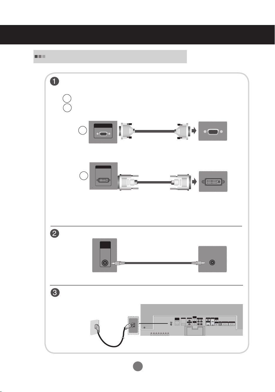
When Connecting to your PC
1.
First of all, see if the computer, product and the peripherals are turned off.
Then, connect the signal input cable.
When connecting with the D-Sub signal input cable.
A
When connecting with the DVI signal input cable.
B
RGB IN
A
Rear side of the product.
DVI IN
PC
B
* User must use shielded signal interface cables (D-sub 15 pin cable, DVI cable) with ferrite cores
to maintain standard compliance for the product.
Connect the Audio cable.
Rear side of the product.
AUDIO
(RGB/DVI)
PC
Rear side of the product.
PC
Connect the power cord.
Rear side of the product.
10
Connecting to External Devices
AUTO/SET
SOURCE
SOURCE
MENU
INPUT
SET
INPUT
SOURCE
SET
AUTO/SET
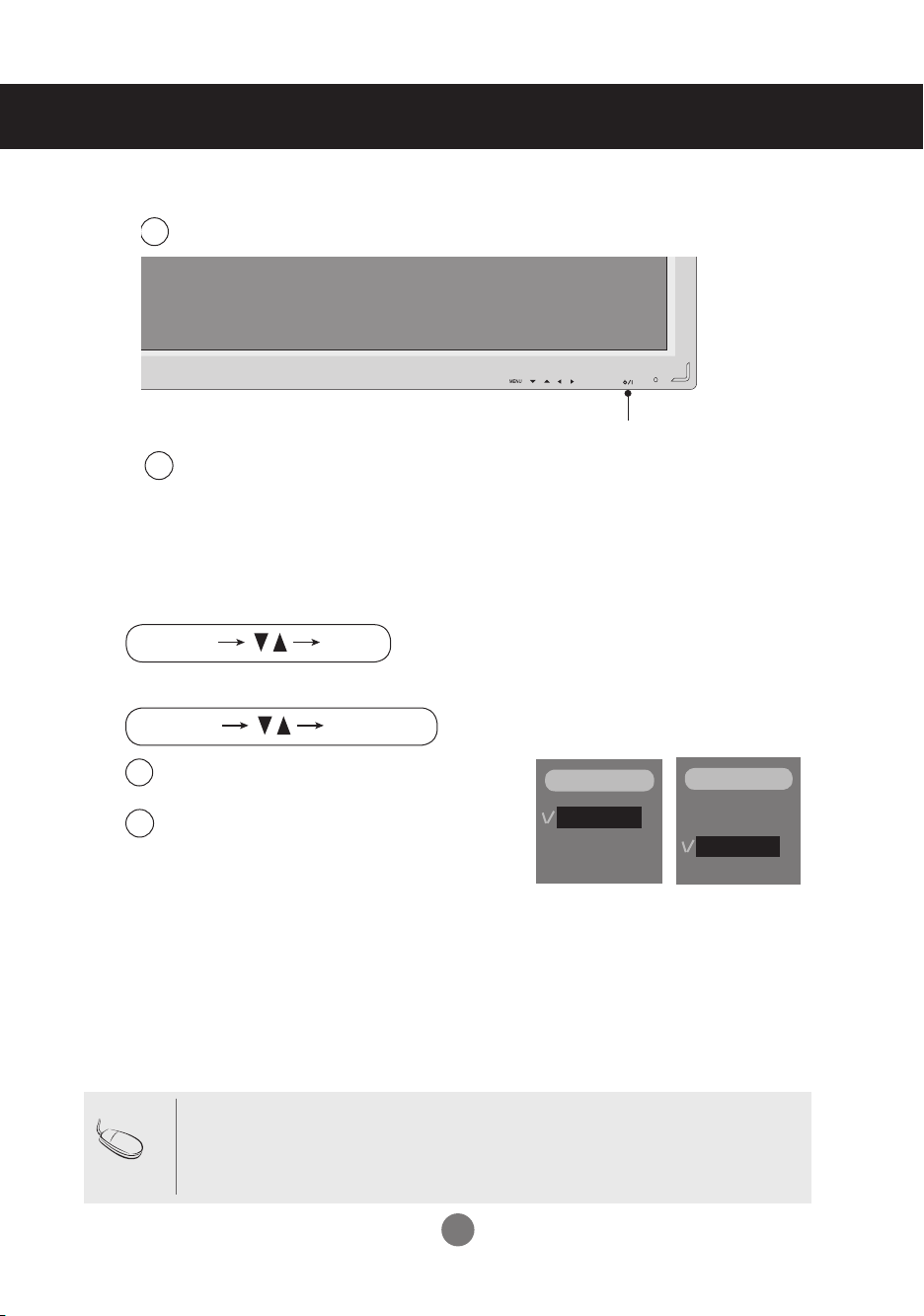
2.
3.
Turn on power by pressing the power button on the product.
1
Power button
Turn on the PC.
2
Select an input signal.
Press the INPUT button on the remote control to select the input signal.
Or, press the SOURCE button at the back side of the product.
When connecting with a D-Sub signal input cable.
A
▪ Select RGB : 15-pin
When connecting with a
B
▪ Select DVI :
D-Sub
DVI
Digital signal.
analog signal.
DVI signal input cable.
INPUT
RGB
DVI
INPUT
RGB
DVI
Note
▪
How to connect to two computers.
Connect the signal cables (DVI and D-Sub) to each computer.
Press the INPUT button in a remote control to select the computer to use.
▪
Directly connect to a grounded power outlet on the wall or a power bar with a ground wire.
11
Connecting to External Devices
RGB IN
RGB OUT
RGB IN
RGB OUT
RGB IN
RGB OUT
RGB IN
RGB OUT
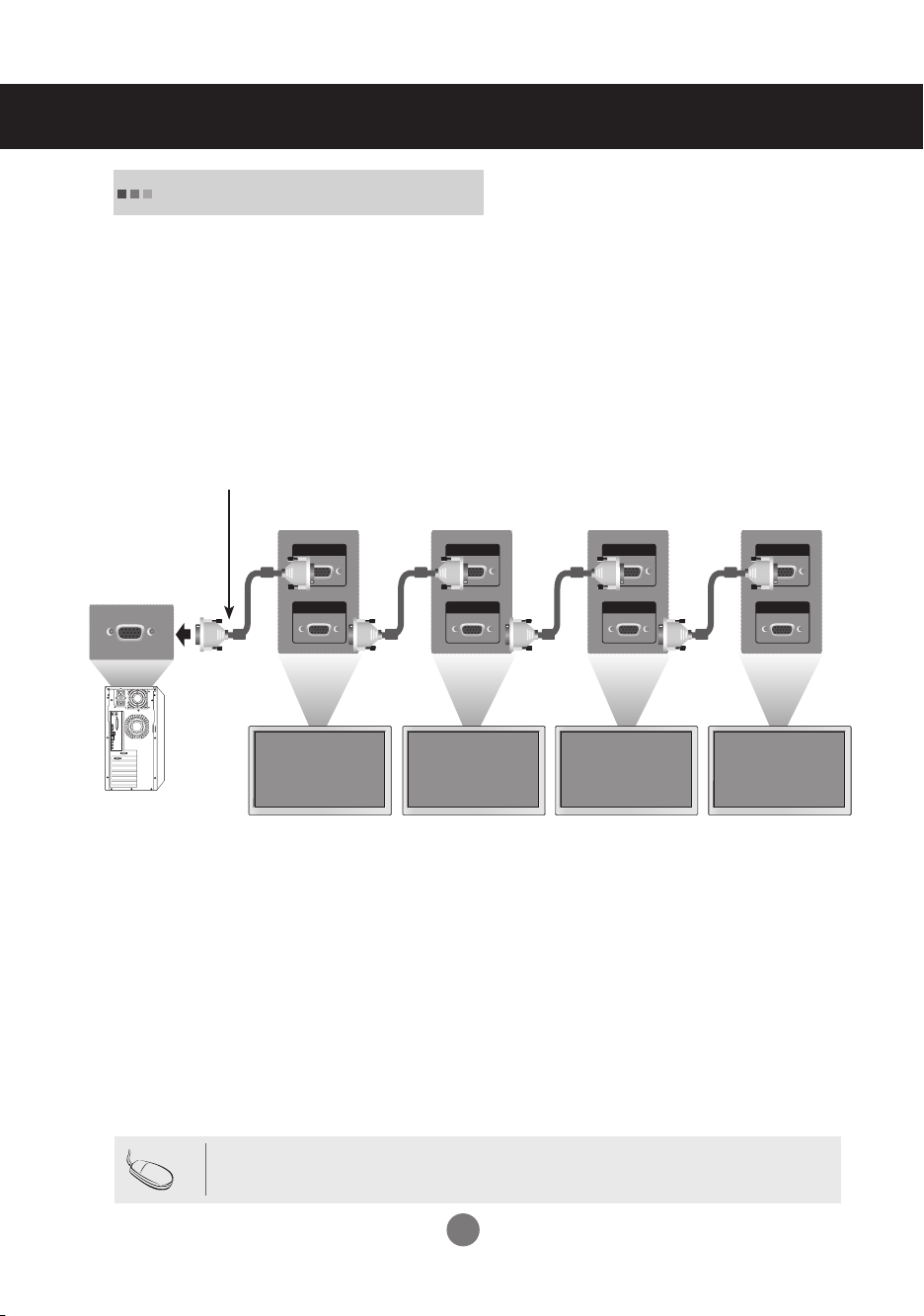
Watching RGB Outputs
Use this function when displaying ANALOG RGB inputs of a PC to the other product.
▪
To use different products connected to each other
Connect one end of the signal input cable(15-pin D-Sub Signal Cable) to the RGB OUT
connector of product 1 and connect the other end to the RGB IN connector of other
products.
15-pin D-Sub Signal Cable
PC
Note
Product 1
Product 2
Product 3
Product 4
▪ When multi-connecting in/out cascade format, cables to be less damaged are recommended.
We recommend that you should use cable distributor.
12
Selecting and Adjusting the Screen
AUTO/SET
SOURCE
SOURCE
MENU
AUTO/SET
SOURCE
AUTO/SET
SOURCE
MENU
AUTO/SET
SOURCE
MENU
AUTO/SET
SOURCE
MENU
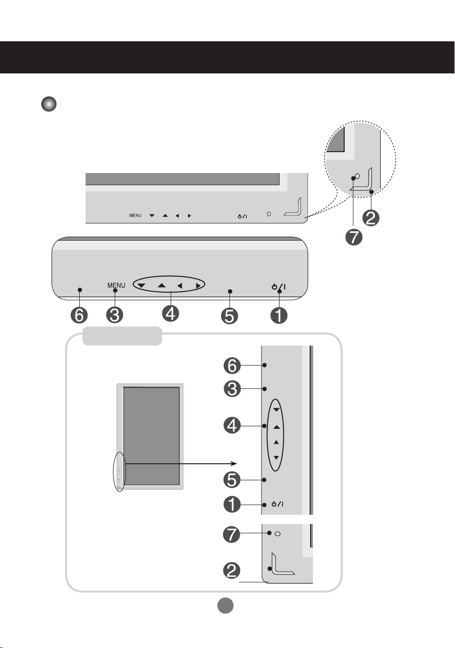
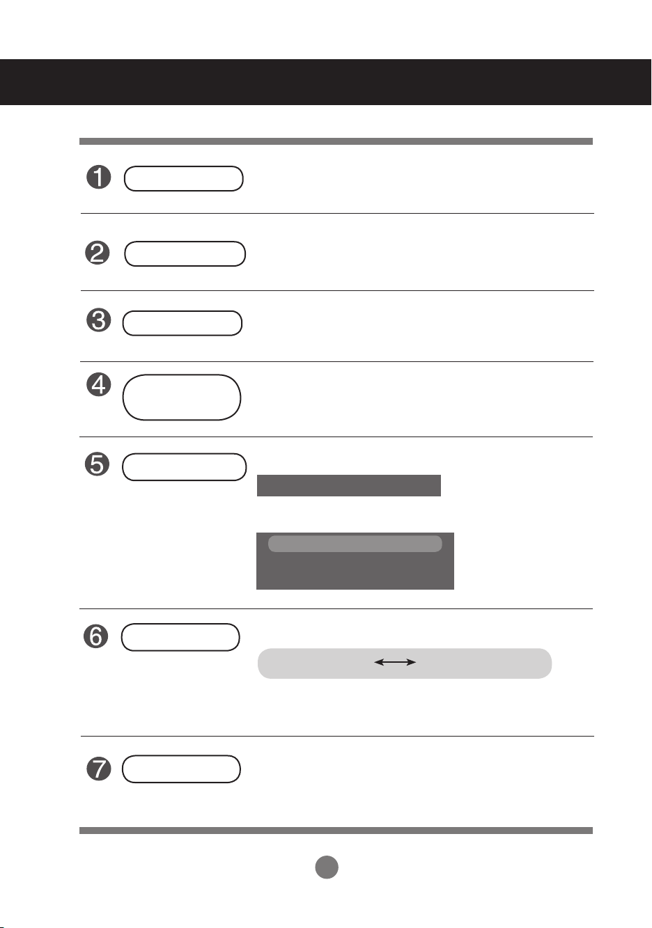
Name of the Buttons in the Screen Adjustment Unit
Pivot model Only
13
Selecting and Adjusting the Screen
Power Button
Power Indicator
MENU Button
OSD Select /
Adjust Button
AUTO/SET Button
▪ Press this button to turn on the power. Press this button again
to turn it off.
▪ This Indicator lights up blue when the display operates
normally(on mode). If the display is in sleep (Power Saving)
mode, this indicator color changes to amber.
▪ Use this button to show/hide the OSD (On Screen Display)
menu screen.
▪
Use
this
button to select an icon or adjust the setting in the OSD screen.
If the resolution is 1920X1080 (RGB Mode)
Auto in progress
If the resolution is not 1920X1080 (RGB Mode)
Auto in progress
For optimal display
Change resolution to 1920 X 1080
SOURCE Button
IR Receiver
▪
Select the input signal
DVI (Digital signal) RGB(Analog signal)
Digital signal and Analogue signal can't be outputted at the same
time so when transferring the source connect the connector and
then turn on the power.
▪ The unit that receives the signal from the remote control.
14
Selecting and Adjusting the Screen
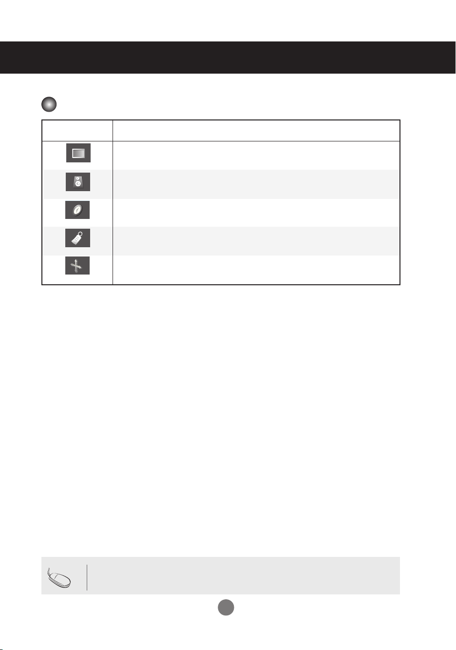
OSD Menu
Icon Function Description
Adjusts screen brightness, contrast and color that you prefer.
PICTURE
SOUND
TIMER
SPECIAL
SCREEN
Adjusts the audio function.
Adjust the time function
Adjusts the screen status according to the circumstances.
Adjusts the screen video.
Nota
▪ OSD (On Screen Display)
The OSD function enables you to adjust the screen status conveniently since it provides graphi-
cal presentation.
15
Selecting and Adjusting the Screen
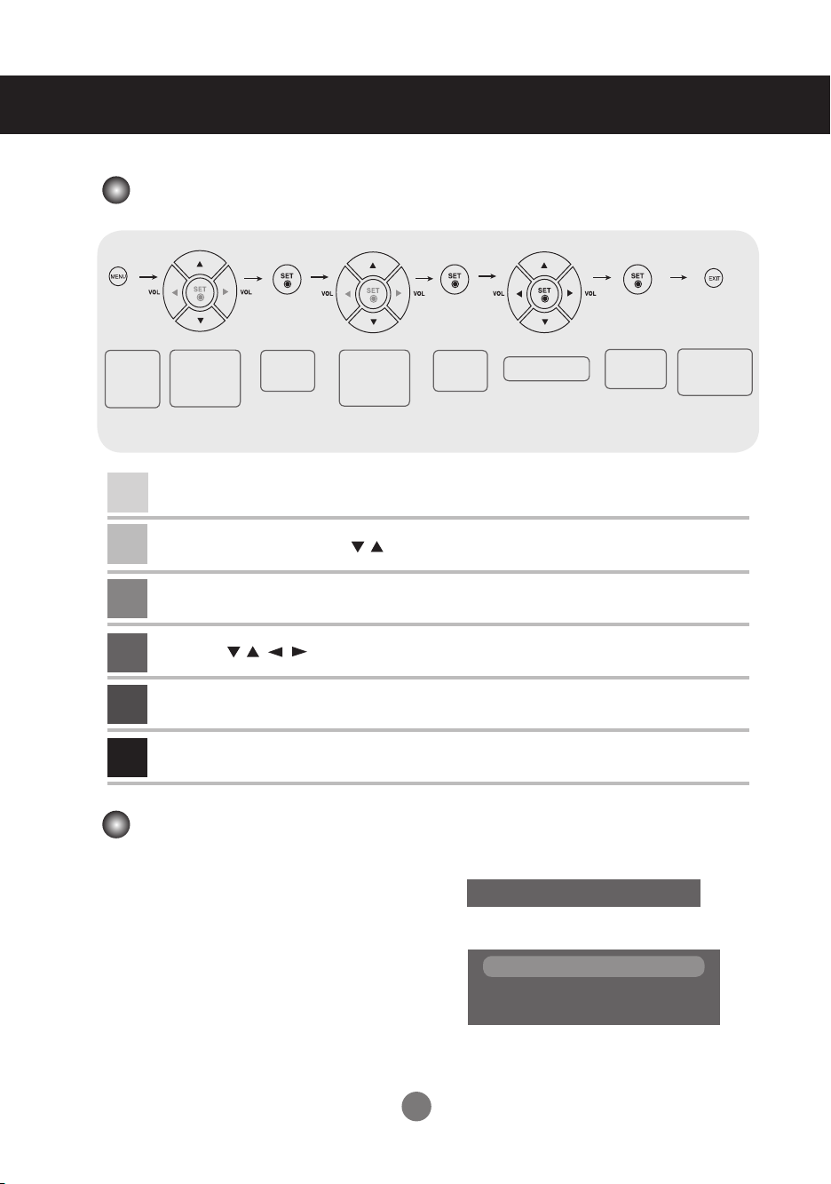
How to adjust the OSD (On Screen Display) screen
Pops up
the menu
screen
Move where
you want to
adjust
Press the MENU Button, then the main menu of the OSD appears.
1
To access a control, use the Buttons.
2
When the icon you want becomes highlighted, press the SET Button.
3
Use the Buttons to adjust the item to the desired level.
4
Accept the changes by pressing the SET Button.
5
Exit the OSD by pressing the EXIT Button.
6
Select a
menu icon
Move where
you want to
adjust
▪
Select a
menu icon
Use the remote control to adjust the OSD screen.
How to adjust the screen automatically
You need to adjust the screen display when connecting the product to a new computer or changing the
mode. Refer to the following section to set an optimal product screen.
Press the AUTO/SET button (AUTO button in a
remote Control) in the PC analog signal. Then, an
optimal screen status will be selected that fits into
the current mode.
If adjustment is not satisfactory, you need to adjust
screen position, clock and phase in the OSD menu.
If the resolution is 1920X1080 (RGB Mode)
If the resolution is not 1920X1080 (RGB Mode)
Change resolution to 1920 X 1080
Adjust the status
Auto in progress
Auto in progress
For optimal display
Save
adjustment
Exit from the
menu screen.
16
 Loading...