

LG M4213CG Users manual

Order Number : GETEC-C1-09-152 FCC Class B Certification
Test Report Number : GETEC-E3-09-082 Page 1 / 1
APPENDIX G
: USER’S MANUAL
EUT Type: LCD Monitor
FCC ID.: BEJM4213CG

User’s Guide
M4213C
Make sure to read the
Keep the User's Guide(CD) in an accessible place for future reference.
Safety Precautions
before using the product.
See the label attached on the product and give the information to your dealer when you ask
for service.
Sellers or users should understand that this device is for public use,
not home use.
Connecting
- Only on some models.
the stand
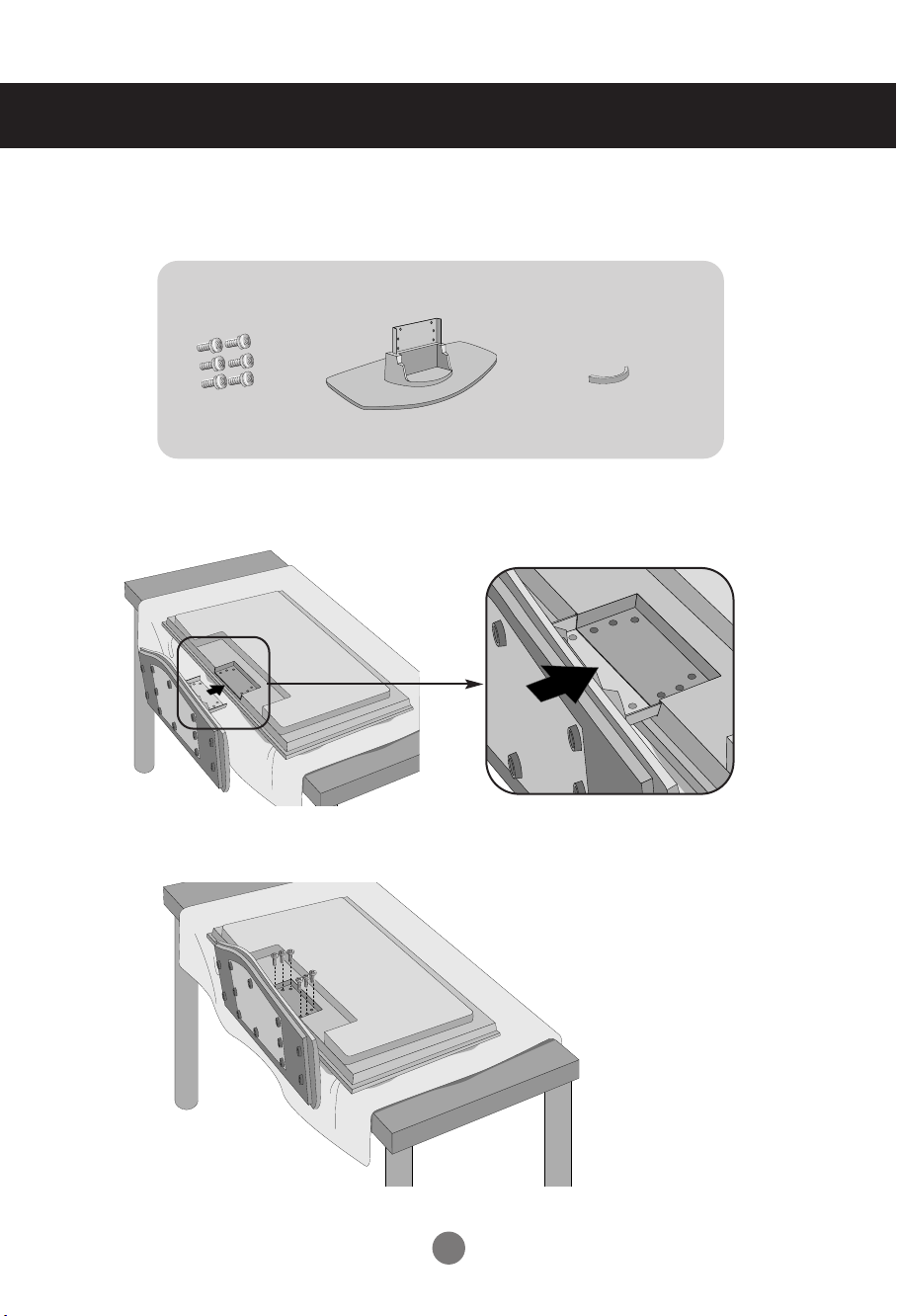
1. Take the parts for the stand out of the box and assemble them as
shown in the picture.
Parts
Screws (6)
First, check if the following parts are all present.
Stand (1)
cable management (1)
2. Place a soft cloth on the table and put the product with the screen
facing downward. Connect the stand as shown in the following picture.
3. Use the screws to secure the stand on the rear side of the product as shown
in the diagram.
1
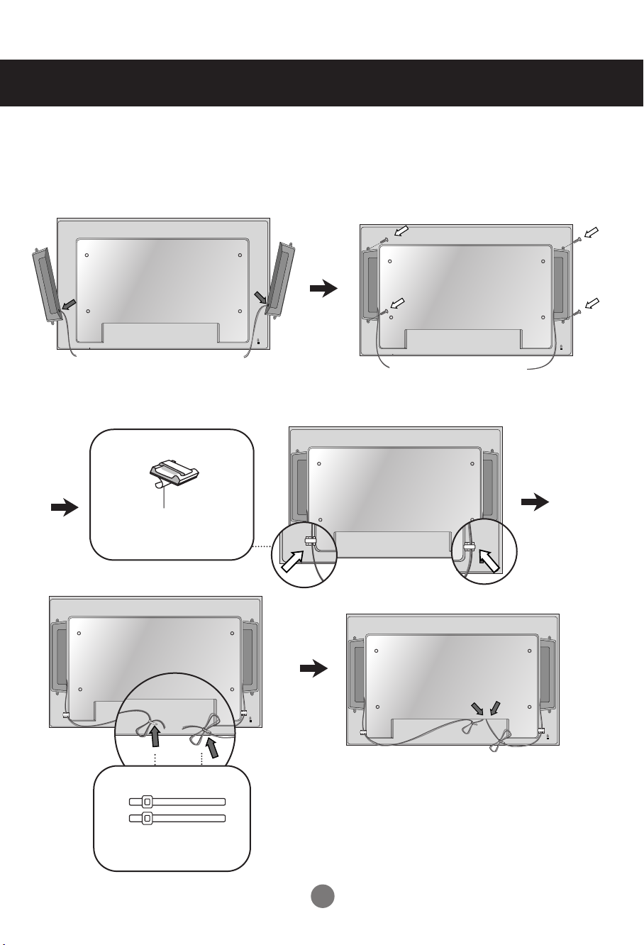
Connecting the Speakers
- Only on some models.
Mount the product onto the speaker by using a screw as shown in the following
connect the speaker cable.
After installing your speakers, use holders and cable ties to organize the speaker cables.
Cable holder
Remove the paper.
* This feature is not available in all model.
Cable tie
* This feature is not available in all model.
When the speaker is installed.
*Connect the input terminal with a proper color match.
2
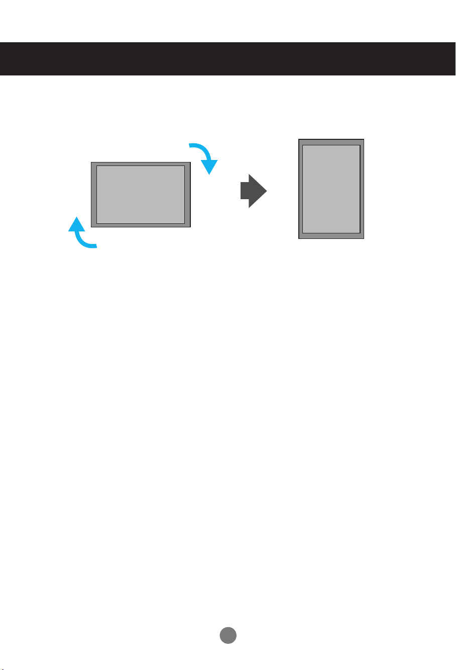
To install Portrait
- Only on some models.
"When installing Portrait, rotate it clockwise based on its front."
3
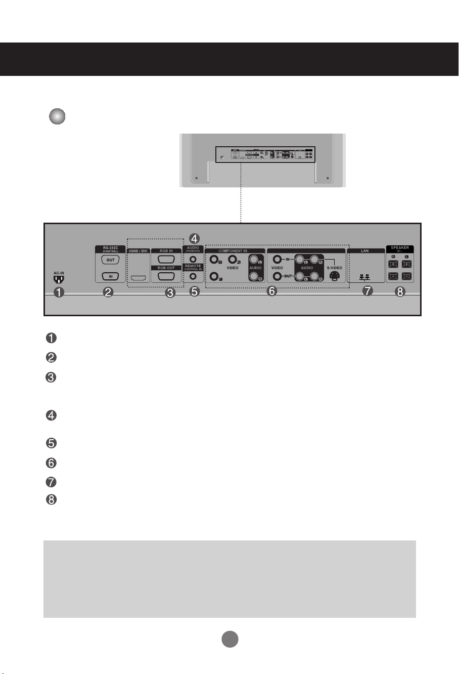
Name and Function of the Parts
AV IN/OUT
AV IN/OUT
* The product image in the user’s guide could be different from the actual image.
Rear View
Power Connector : Connect the power cord
RS-232C Serial Ports
RGB PC, HDMI/DVI Ports
-HDMI Supports High Definition input and HDCP (High-bandwidth Digital Content
Protection). Some devices require HDCP in order to display HD signals.
PC Sound Jack
: Connect the audio cable to the *LINE OUT jack of the PC sound card.
Wired Remote Control Port
AV Ports
LAN Port
Speaker Ports
*LINE OUT
A terminal used to connect to the speaker including a built-in amplifier (Amp). Make sure that
the connecting terminal of the PC sound card is checked before connecting. If the Audio Out of
PC sound card has only Speaker Out, reduce the PC volume.
If the Audio Out of the PC sound card supports both Speaker Out and Line Out, convert to Line Out using
the card jumper of the program (Refer to the Sound Card Manual).
6
Connecting to External Devices
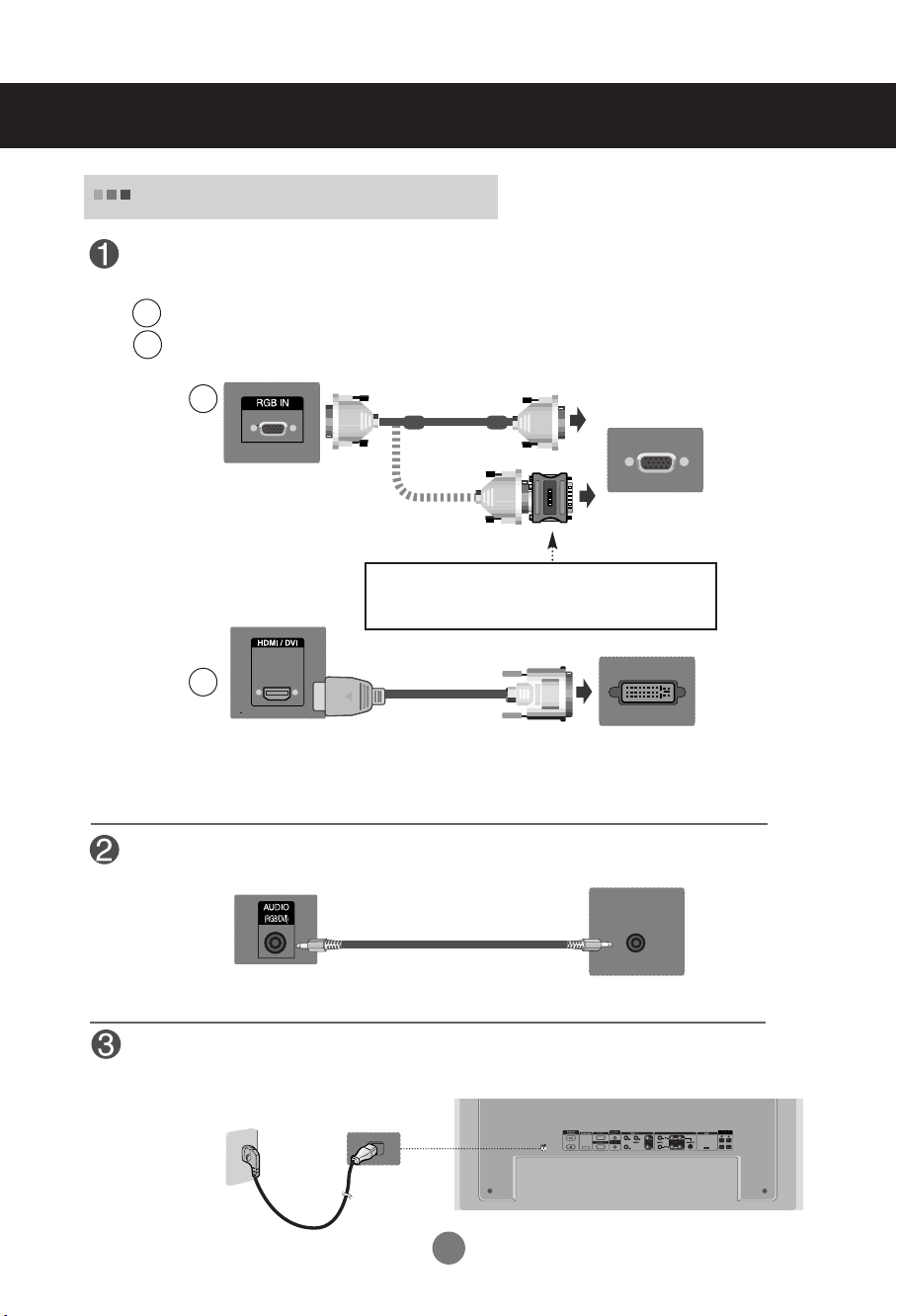
When Connecting to your PC
First of all, see if the computer, product and the peripherals are turned off.
Then, connect the signal input cable.
When connecting with the D-Sub signal input cable.
A
When connecting with the HDMI to DVI signal input cable (not included).
B
* When HDMI PC is used, a compatibliy problem might occur.
A
PC
Rear side of the product.
PC/
MAC
Macintosh Adapter (not included)
Use the standard Macintosh adapter since an incompatible
adapter is available in the market. (Different signaling system)
B
MAC
Rear side of the product.
* User must use shielded signal interface cables (D-sub 15 pin cable, DVI cable) with ferrite cores to maintain
standard compliance for the product.
(not included)
PC
Connect the Audio cable.
Rear side of the product.
PC
Connect the power cord.
Rear side of the product.
AV IN/OUT
7
Connecting to External Devices
Network
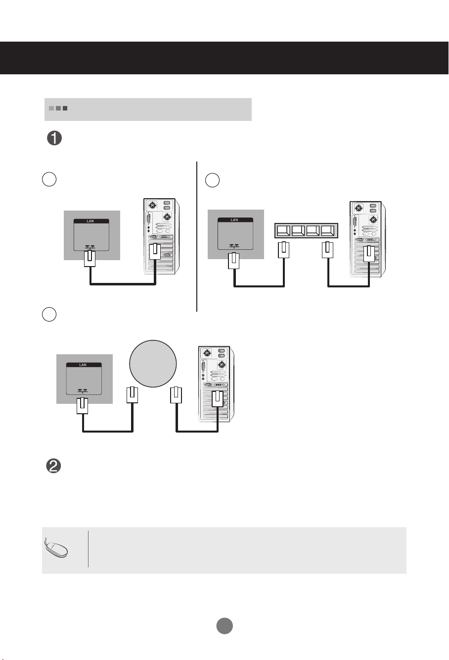
When using the LAN
Connect the LAN cable as shown in the below figure .
Connect PC to Monitor directly
A
Product
Using the Internet
C
LAN
Product
Using a router(Switch)
B
LAN
Switch
PC PC
Product
PC
Connect the LAN cable and install the eZ-Net Manager program on the CD-ROM.
For more information about the program, please refer to eZ-Net Guide in the enclosed
CD-ROM.
Note
• Using LAN establishes communication between your PC and the monitor and enables to
use the OSD menus on the PC as well as on the monitor.
9
RGB IN
RGB OUT
RGB IN
RGB OUT
RGB IN
RGB OUT
RGB IN
RGB OUT
Connecting to External Devices
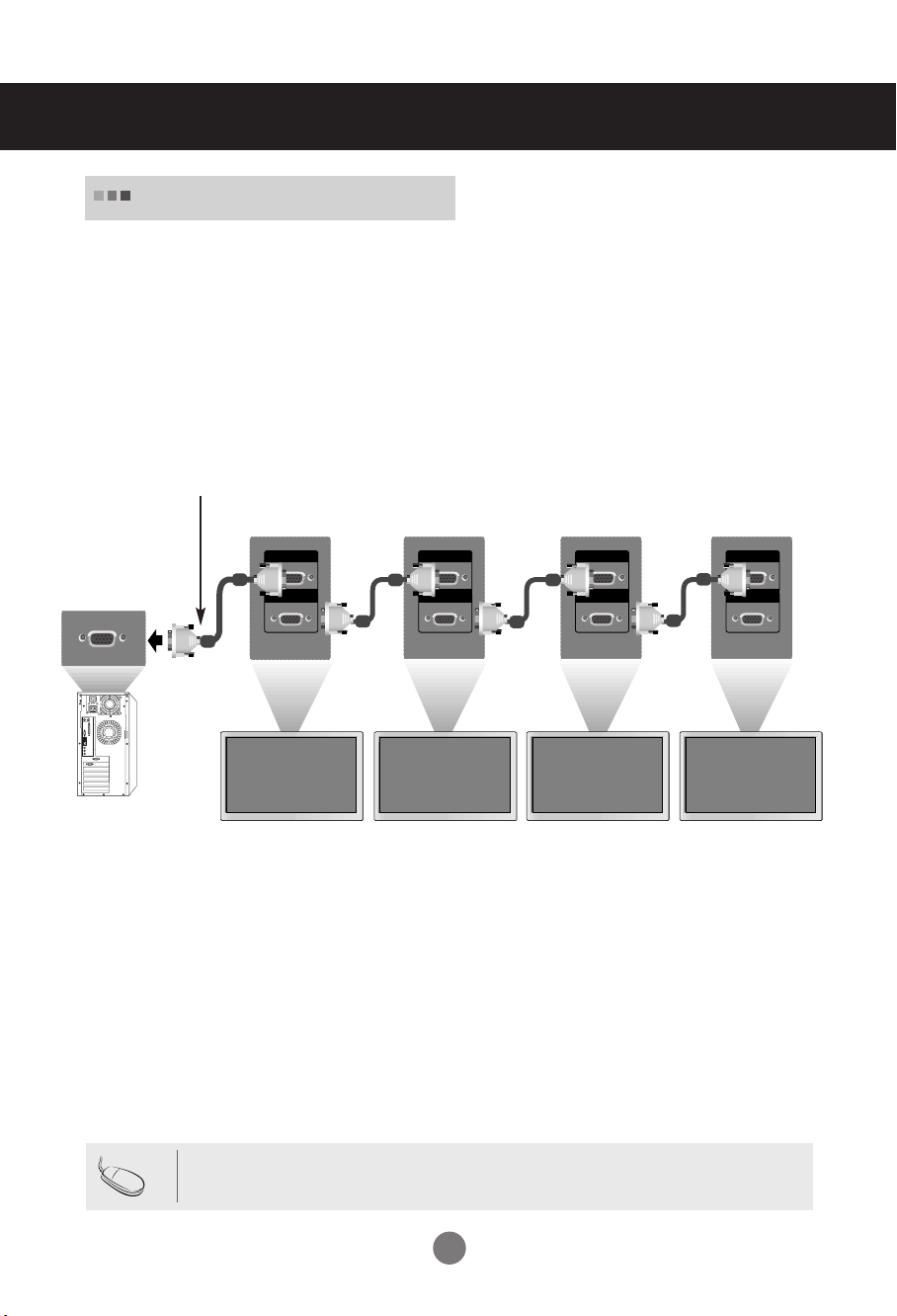
Daisy Chain Monitors
Use this function when displaying ANALOG RGB inputs of a PC to the other product.
•
To use different products connected to each other
Connect one end of the signal input cable(15-pin D-Sub Signal Cable) to the RGB OUT
connector of product 1 and connect the other end to the RGB IN connector of other
products.
15-pin D-Sub Signal Cable
PC
PC
Note
Product 1
Product 2
• When multi-connecting in/out cascade format, no loss cables are recommended.
Product 3
Product 4
We recommend that you should use cable distributor.
10
Connecting to External Devices
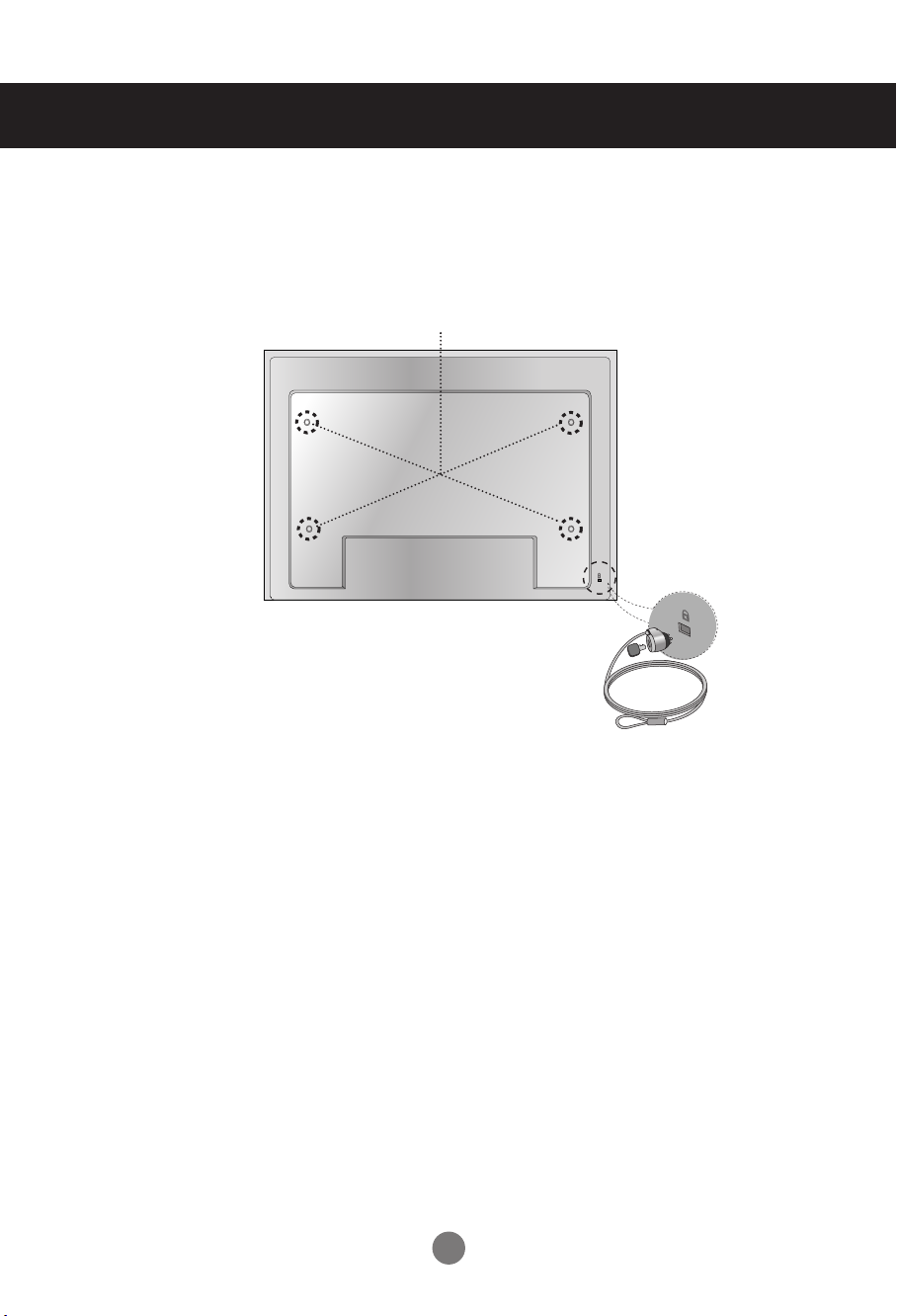
VESA FDMI wall Mounting
This product supports a VESA FDMI compliant mounting interface. These mounts are purchased
separately and not available from LG. Refer to the instructions included with wall mount for more info.
The Set is equipped with a kensington Security
System connector on the back panel. The cable and
lock are available separate and are not sold by LG.
For more info, visit http://www.kensington.com, the
internet home page of the Kensington company.
11
Connecting to External Devices
AUDIO
AV IN/OUT
INPUT SET
SOURCE
AUTO/SET
AUDIO
AV IN/OUT
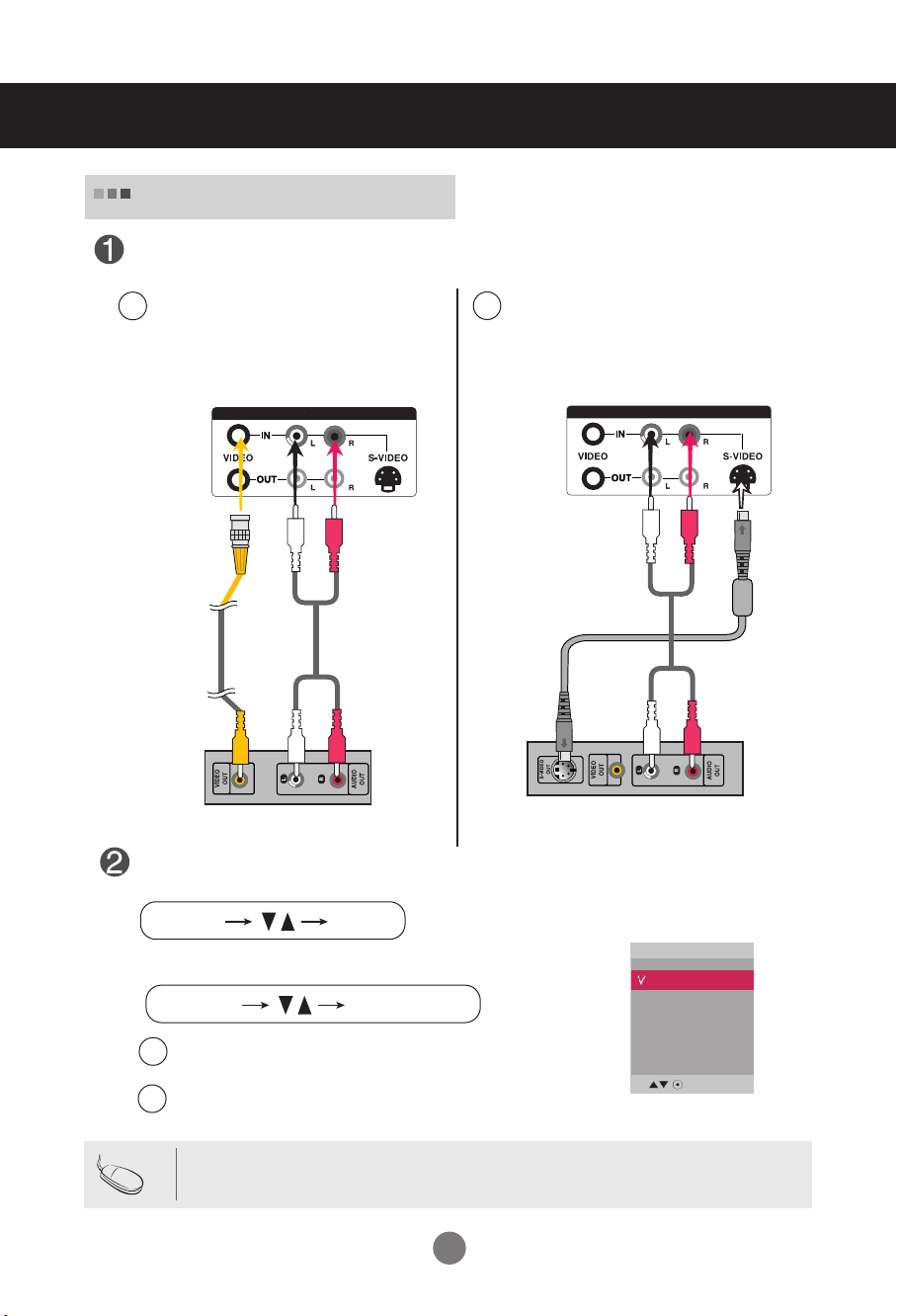
Video Input
Connect the video cable as shown in the below figure and then connect the power
cord (See page 7).
When connecting with a BNC cable.
A
•
Connect the input terminal with a
proper color match.
When connecting with a S-Video cable.
B
•
Connect to the S-Video input terminal to
watch high image quality movies.
Product
BNC Cable
(not included)
Product
Audio Cable
(not included)
VCR/DVD Receiver
Audio Cable
(not included)
VCR/DVD Receiver
Select an input signal.
Press the INPUT button on the remote control to select the input signal.
Or, press the SOURCE button on the back of the product.
When connecting with an BNC cable.
A
Select AV.
•
When connecting with an S-Video cable.
B
•
Select AV.
Input
AV
Component
RGB PC
HDMI/DVI
S-Video Cable
(not included)
Note
• When the BNC cable is connected simultaneously with S-Video cable, S-Video input has a priority.
12
 Loading...