

LG M4210LC, M4210LCBA, M4210L Owner's Manual

OWNER’S MANUAL
MONITOR SIGNAGE
MONITOR SIGNAGE MODEL
M4210L
www.lg.com
Please read this manual carefully before operating
your set and retain it for future reference.
ENGLISH


Connecting the stand .................................................................4
Connecting the Speakers ..........................................................5
Portrait Mode ..............................................................................6
Using the Remote Control .........................................................7
Remote Control Buttons ....................................................................................................7
Inserting Batteries into the Remote Control ...................................................................8
Part Names and Functions ........................................................9
Connecting to External Devices................................................10
When Connecting to Your PC ...........................................................................................10
VESA FDMI Wall Mounting .................................................................................................12
Video Input ...........................................................................................................................13
HDMI Input (480p/576p/720p/1080i/1080p) ......................................................................14
Watching AV Outputs..........................................................................................................15
User Menus .................................................................................16
Screen Adjustment Options ..............................................................................................16
OSD Menu ............................................................................................................................18
How to Adjust the OSD (On-Screen Display) ..................................................................19
Adjusting the Screen Automatically .................................................................................19
Adjusting Screen Color ......................................................................................................20
Adjusting Audio ...................................................................................................................25
Adjusting the Timer.............................................................................................................26
Selecting Options ...............................................................................................................28
Adjust Set ID and Check Serial No. and SW Version.....................................................32
Troubleshooting .........................................................................33
Specifications ...........................................................................36
Table of Contents
4
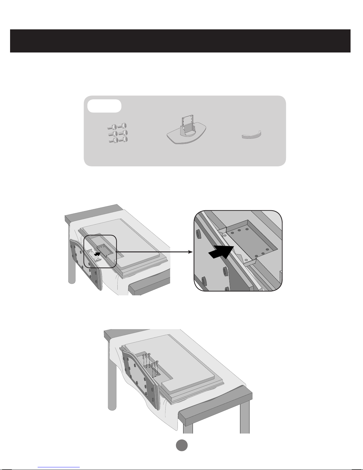
Connecting the stand
- Only on some models.
1. Take the parts for the stand out of the box and assemble them as shown in the
picture below.
2. Place a soft cloth on the table and place the screen downward. Connect the stand
as shown in the following picture.
3. Use the screws to secure the stand on the rear side of the product as shown in the
diagram.
First, check that the following parts have been included.
Parts
Stand (1)
Screws (6)
Cable management (1)
5
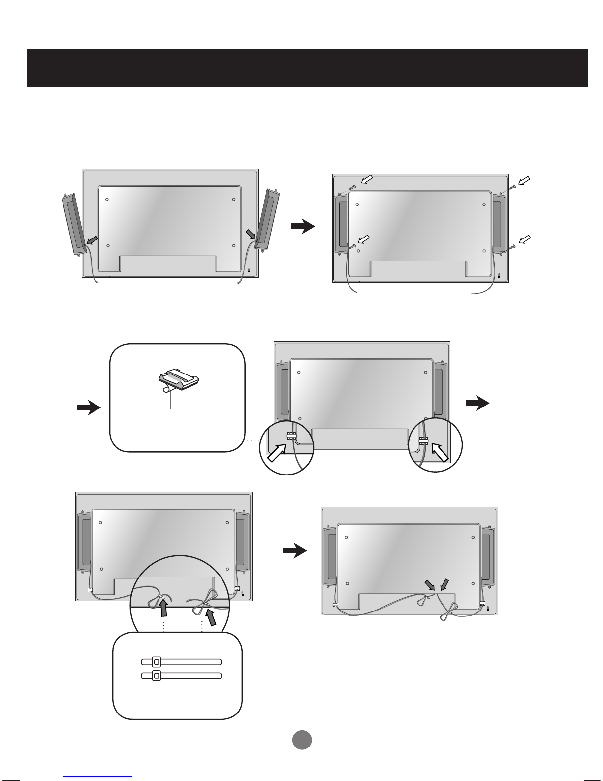
Connecting the Speakers
Mount the speakers onto the sets using screws as shown below.
- Only on some models.
When the speaker is installed.
*Connect the input terminal with the proper color.
Remove the paper.
Cable holder
After installing your speakers, use cable holders and ties to organize the cables.
* This feature is not available on all models.
Cable Ties
* This feature is not available on all models.
6
6
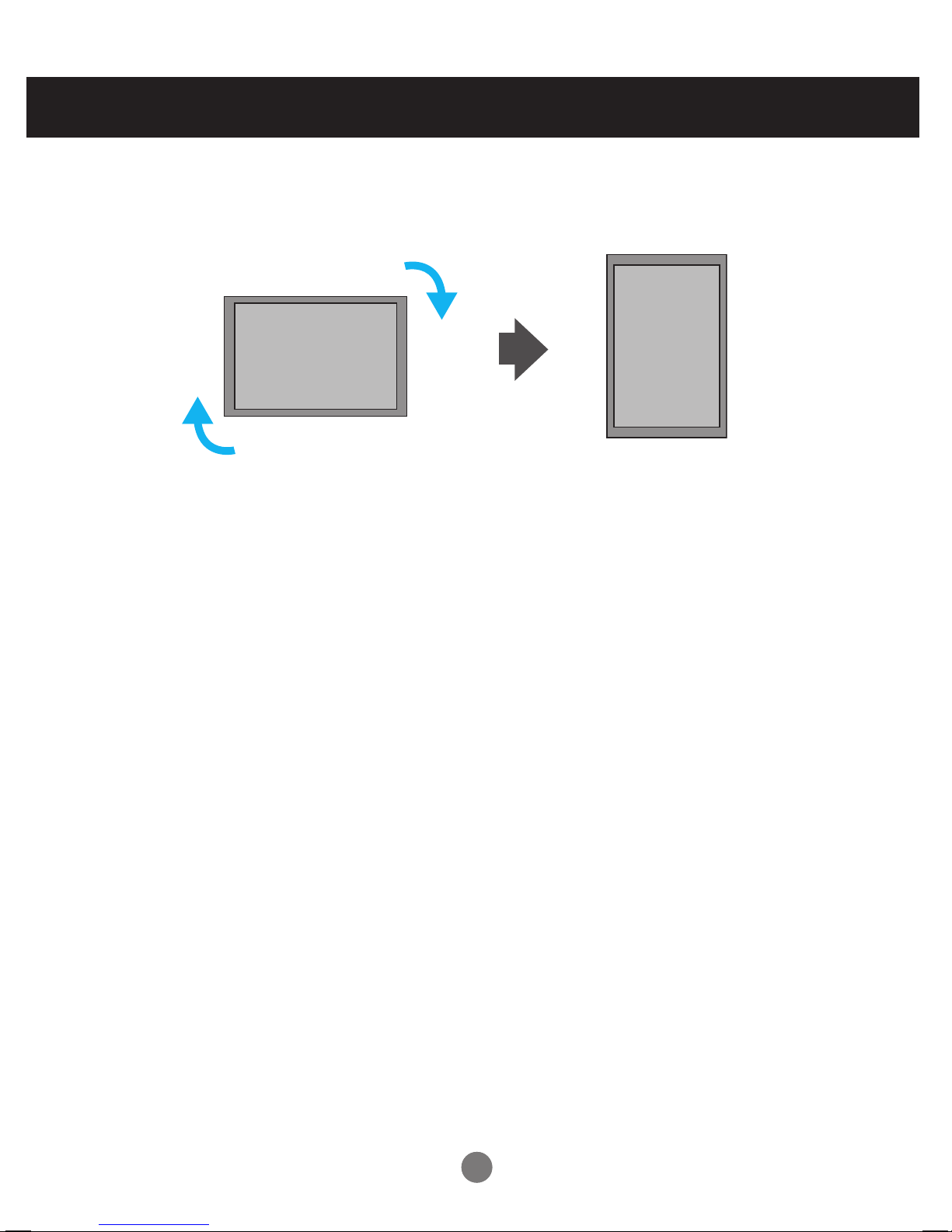
Portrait Mode
" When installing in portrait mode, rotate the sets clockwise when looking
at the unit from the front."
- Only on some models.
7
7
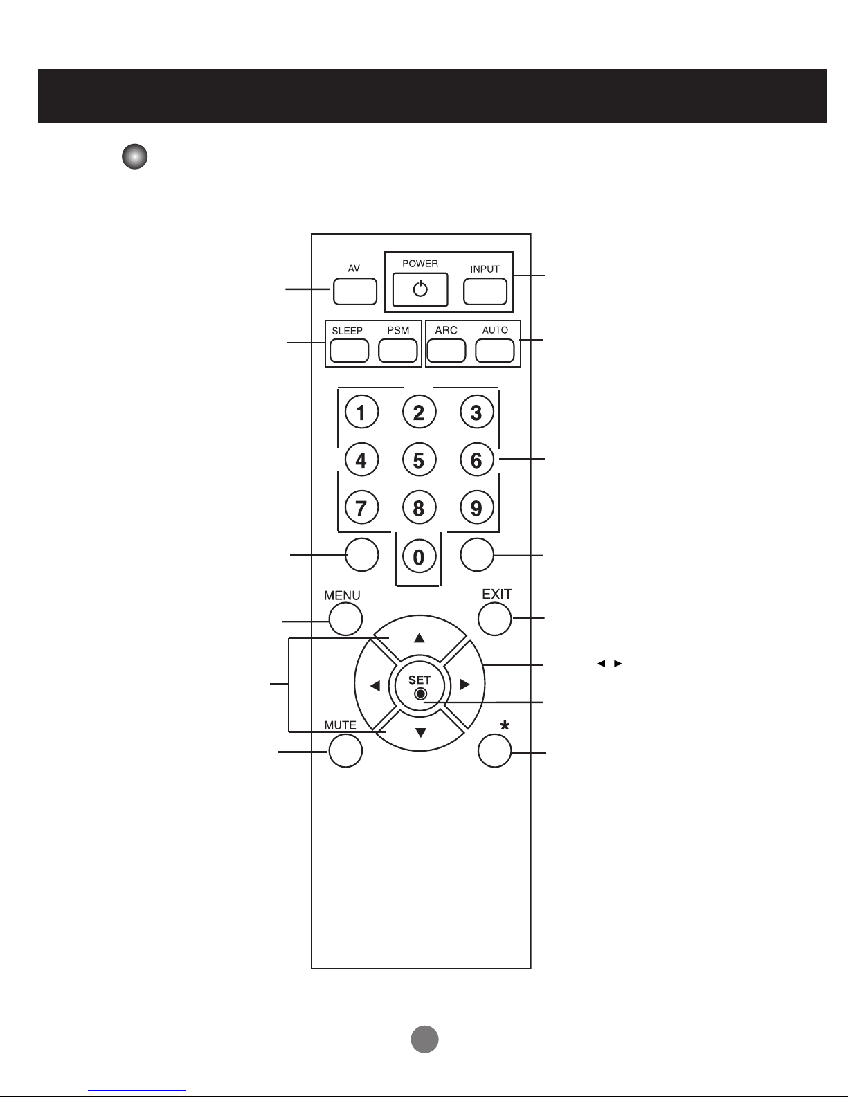
Using the Remote Control
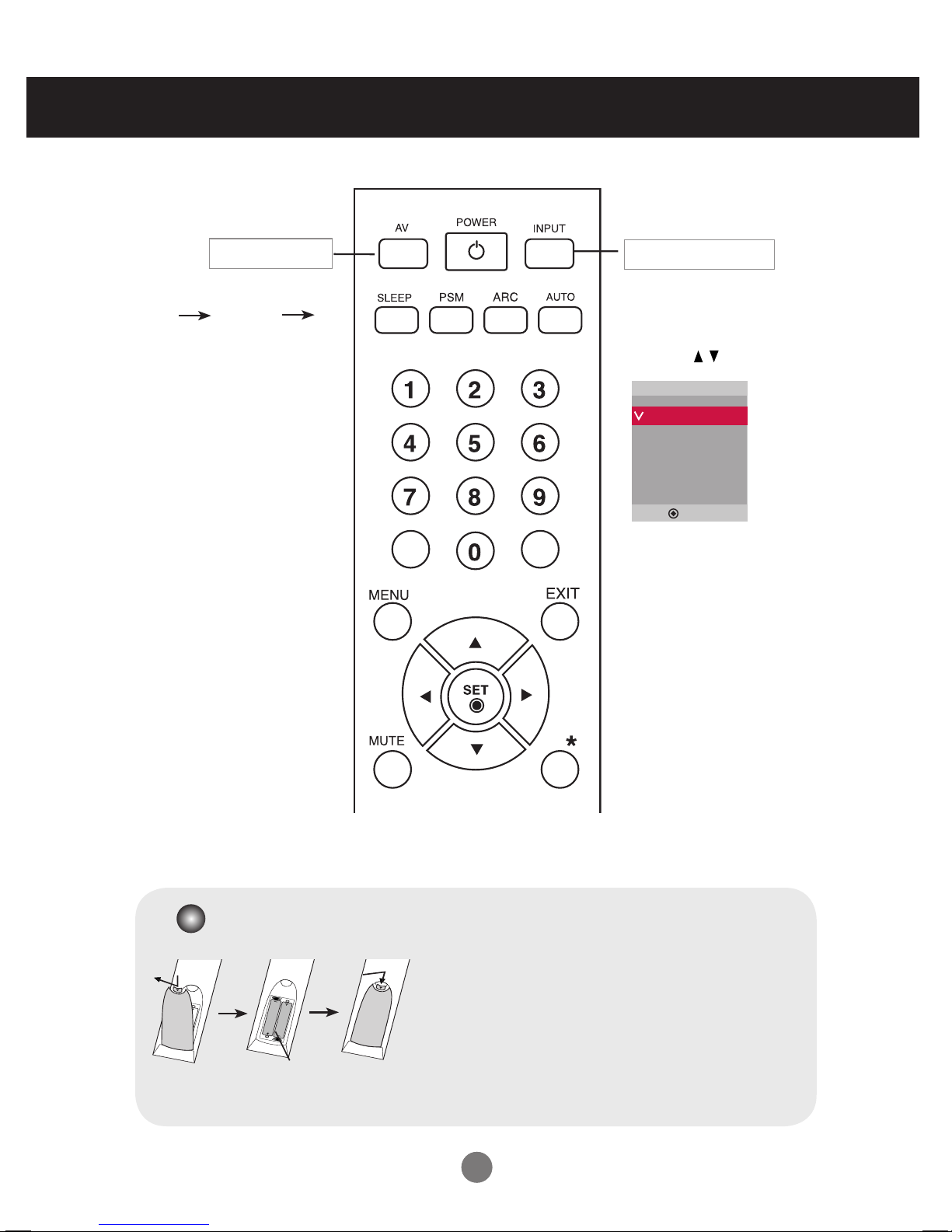
Remote Control Buttons
• AV Button
• Sleep Button
When watching AV, RGB PC,HDMI/DVI.
The product will be automatically turned
off after a certain period of time.
Press this button repetitively to
select an appropriate time duration
• PSM Button
- Toggles through preset video
settings.
•
Menu Button
• Check Button
• Volume Button
Volume up and down
• Mute button
No supported function
• UP and Down buttons
Bring up and down direction
adjustment.
• ARC button
Aspect Ratio Correction. Toggles
through aspect ratio options.
• Auto Button
Automatic adjustment function
(Operational for the analog signal only)
•
Exit Button
No supported function
No supported function.
No supported function
• Power On/Off Button
• Input Select Button
(See next page)
8
8
Using the Remote Control
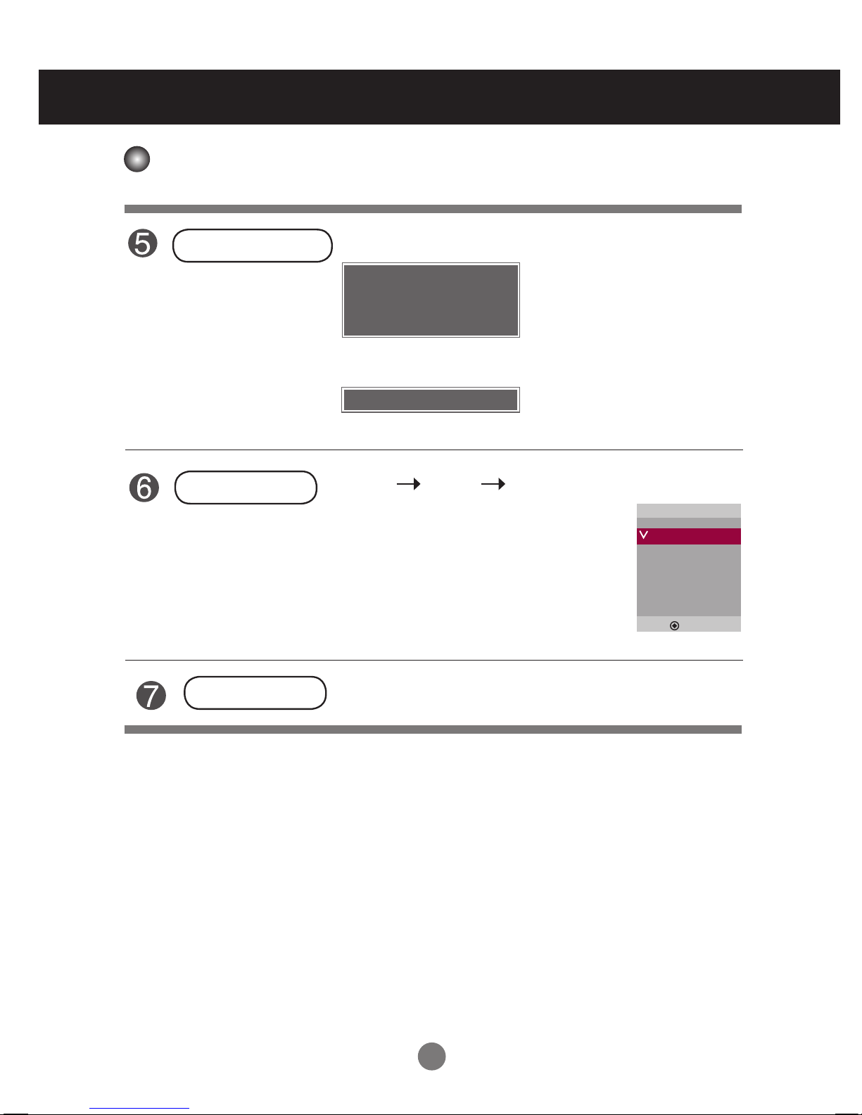
• AV Button
If you press the button once,
the following Input Signal
Window will appear. Select
the signal type you want
using the button.
• Input Select Button
1. Open the battery compartment cover on the back side and
install the batteries matching correct polarity (+ with +,- with -).
2. Install two 1.5 V AAA batteries. Don’t mix old or used batteries
with new ones.
3. Close cover.
4. To remove the batteries, perform the installation actions in
reverse.
Inserting Batteries into the Remote Control
AAA Type
AV RGB PC
HDMI/DVI
Toggles through video
Input
AV
RGB PC
HDMI/DVI
▲▼
9
9
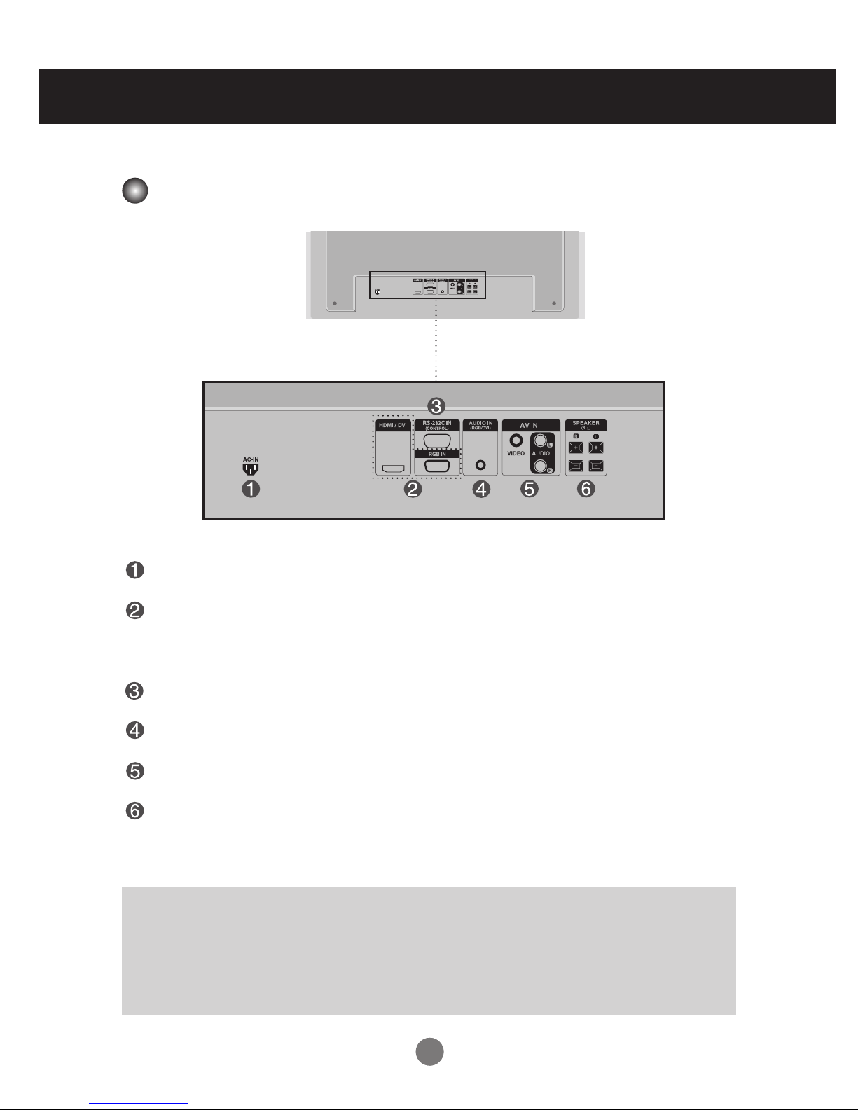
Part Names and Functions
*LINE OUT
A terminal used to connect to the speaker including a built-in amplifier (Amp). Make sure that the
connecting terminal of the PC sound card is checked before connecting. If the Audio Out of PC
sound card has only Speaker Out, reduce the PC volume.
If the Audio Out of the PC sound card supports both Speaker Out and Line Out, convert to Line Out
using the card jumper of the program (see your sound card manual).
* Image shown may differ from your set.
Power Connector : Connect the power cord
RGB PC, HDMI/DVI Ports
- HDMI Supports High Denition input and HDCP (High-bandwidth Digital Content Protection).
Some devices require HDCP in order to display HD signals.
RS-232C Serial Ports
PC Sound Jack : Connect the audio cable to the *LINE OUT jack of the PC sound card.
AV Ports
Speaker Ports
Rear View
10
10
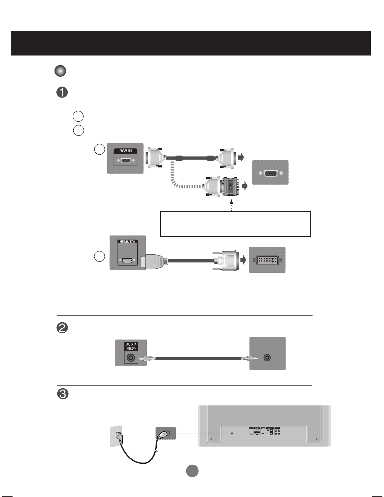
Make sure the computer, product and the peripherals are turned off.
Then, connect the signal input cable.
When connecting with the D-Sub signal input cable.
When connecting with the HDMI to DVI signal input cable (not included).
Connecting to External Devices
B
A
PC
Rear side of the product.
Connect the audio cable.
MAC
Macintosh Adapter (not included)
Use the standard Macintosh adapter since an incompatible adapter is
available on the market(different signaling system).
B
A
PC
PC/
MAC
PC
Rear side of the product.
Rear side of the product.
(not included)
* Use shielded signal interface cables (D-Sub 15-pin cable, DVI cable) with ferrite cores to maintain standard
compliance for the product.
When Connecting to Your PC
Rear side of the product.
Connect the power cord.
11
11
How to connect to two computers.
• Connect the signal cables (HDMI to DVI and D-Sub) to each computer.
• Press INPUT on the remote control to select the computer to use.
• Directly connect to a grounded power outlet on the wall or a power bar with a grounded wire.
Note
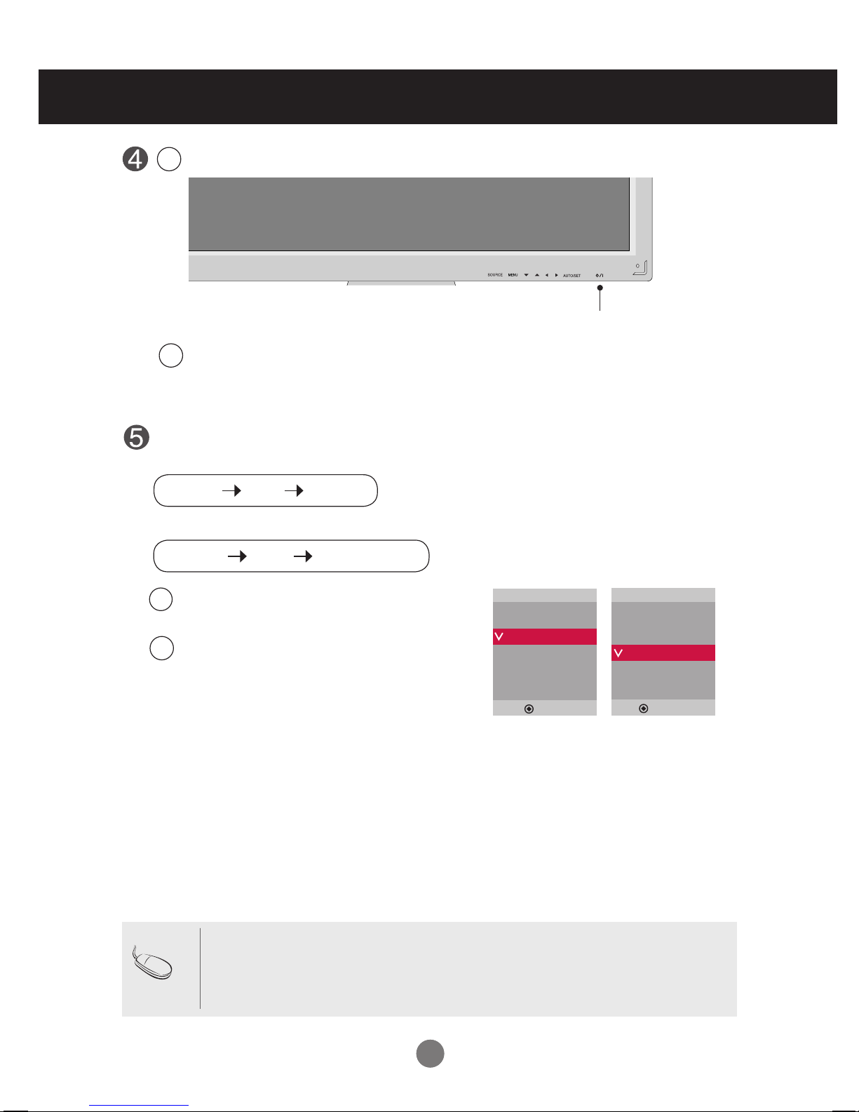
Turn on power by pressing the power button on the product.
Connecting to External Devices
Turn on the PC.
2
1
Select an input signal.
Press the INPUT button on the remote control to select the input signal.
Or, press the SOURCE button on the back of the product.
When connecting with a D-Sub signal input cable.
• Select RGB PC : 15-pin D-Sub analog signal.
When connecting with a HDMI to DVI signal input cable.
• Select HDMI/DVI : HDMI to DVI digital signal.
B
A
Input
AV
RGB PC
HDMI/DVI
Input
AV
RGB PC
HDMI/DVI
▲▼
▲▼
INPUT SET
▼▲
SOURCE
AUTO/SET
▼▲
Power button
12
12
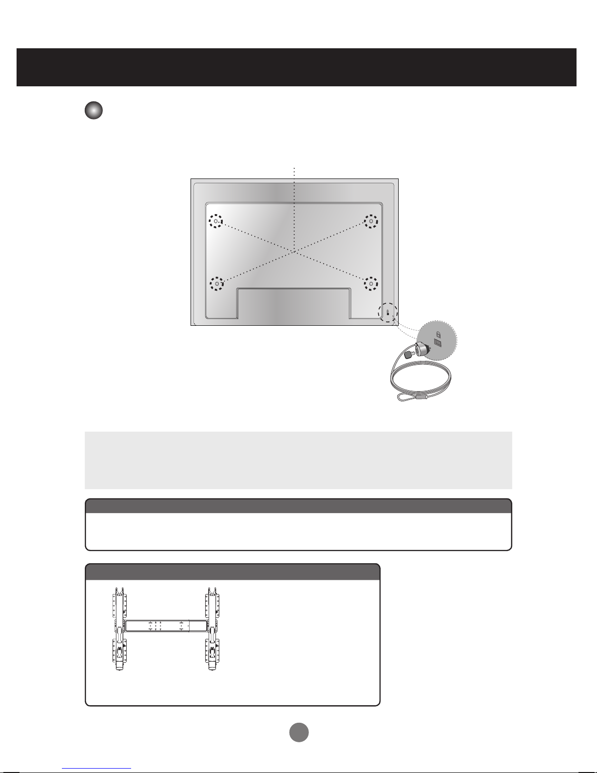
Kensington Security Slot
The Set is equipped with a Kensington Security System
connector on the back panel. The cable and lock are
available separately and are not sold by LG. For more
info, visit http://www.kensington.com
This product supports a VESA FDMI compliant mounting interface. These mounts are purchased
separately and not available from LG. Refer to the instructions included with wall mount for more
info.
Connecting to External Devices
VESA FDMI Wall Mounting
WARNING
•
To prevent injury, this apparatus must be securely attached to the wall according to the installation
instructions.
There is an optional installer remote control available for the M4210L series. The installer remote
control is NOT included with the apparatus.
Optional Installer Remote Control for model No. Series M4210L
Wall Mounting Bracket
(AP-WX60)
Option Extras
13
13
Connecting to External Devices
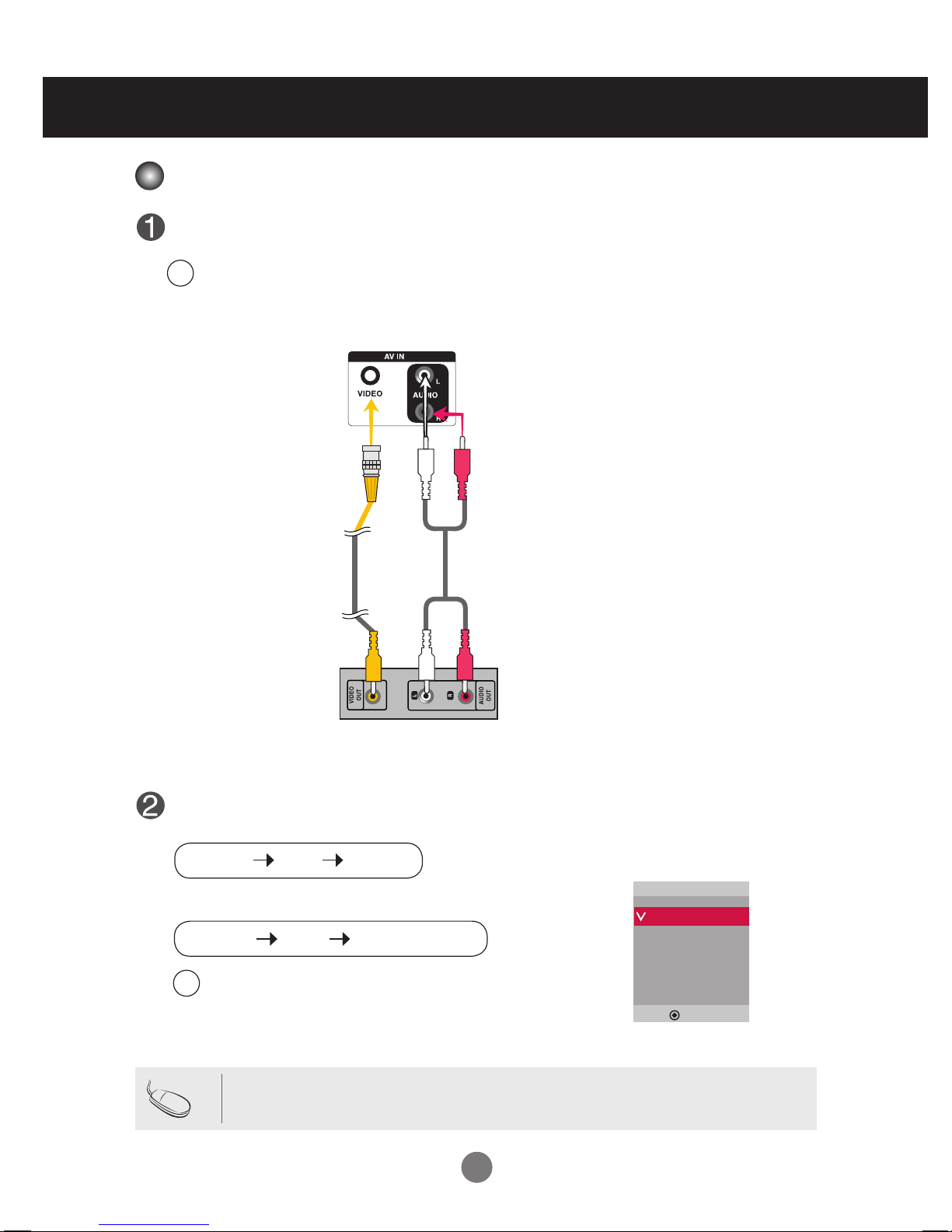
When connecting with an BNC cable.
•
Select AV.
A
Connect the video cable as shown below and then connect the power cord (see page 10).
Connecting with a BNC cable.
•
Connect the input terminal with the proper color.
A
BNC Cable
(not included)
Product
VCR/DVD Receiver
Select an input signal.
Press the INPUT button on the remote control to select the input signal.
Or, press the SOURCE button on the back of the product.
• When the BNC cable is connected simultaneously with an S-Video cable, the S-Video input has
priority.
Note
Audio Cable
(not included)
Input
AV
RGB PC
HDMI/DVI
▲▼
INPUT SET
▼▲
Video Input
SOURCE
AUTO/SET
▼▲
1414
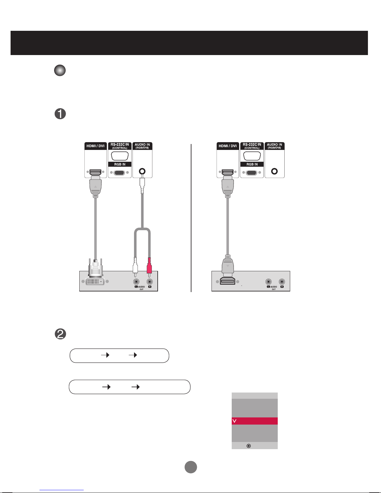
Connect the video/audio cable as shown below and then connect the power cord
(see page 10).
RCA-PC
Audio Cable
(not included)
Product
VCR/DVD/Set-top Box
HDMI to DVI
Signal Cable
(not included)
VCR/DVD/Set-top Box
Product
Select an input signal.
Press the INPUT button on the remote control to select the input signal.
Or, press the SOURCE button on the back of the product.
HDMI Signal Cable
(not included)
Connecting to External Devices
When connecting with an HDMI to DVI signal input cable.
When connecting with an HDMI signal input cable.
• Select HDMI/DVI
- HDMI supports high denition input and HDCP (High-bandwidth Digital Content Protection).
Some devices require HDCP in order to display HD signals.
Note : Dolby Digital is not supported.
Input
AV
RGB PC
HDMI/DVI
▲▼
INPUT SET
▼▲
HDMI Input (480p/576p/720p/1080i/1080p)
SOURCE
AUTO/SET
▼▲

1515
- When using the AV input, you can connect the AV Out to other monitors.
Video/TV
BNC Cable
(not included)
Audio Cable
(not included)
Product
Connecting to External Devices
• When multi-connecting in/out cascade format, no loss cables are recommended.
We recommend using a cable distributor.
Note
Watching AV Outputs
16
User Menus
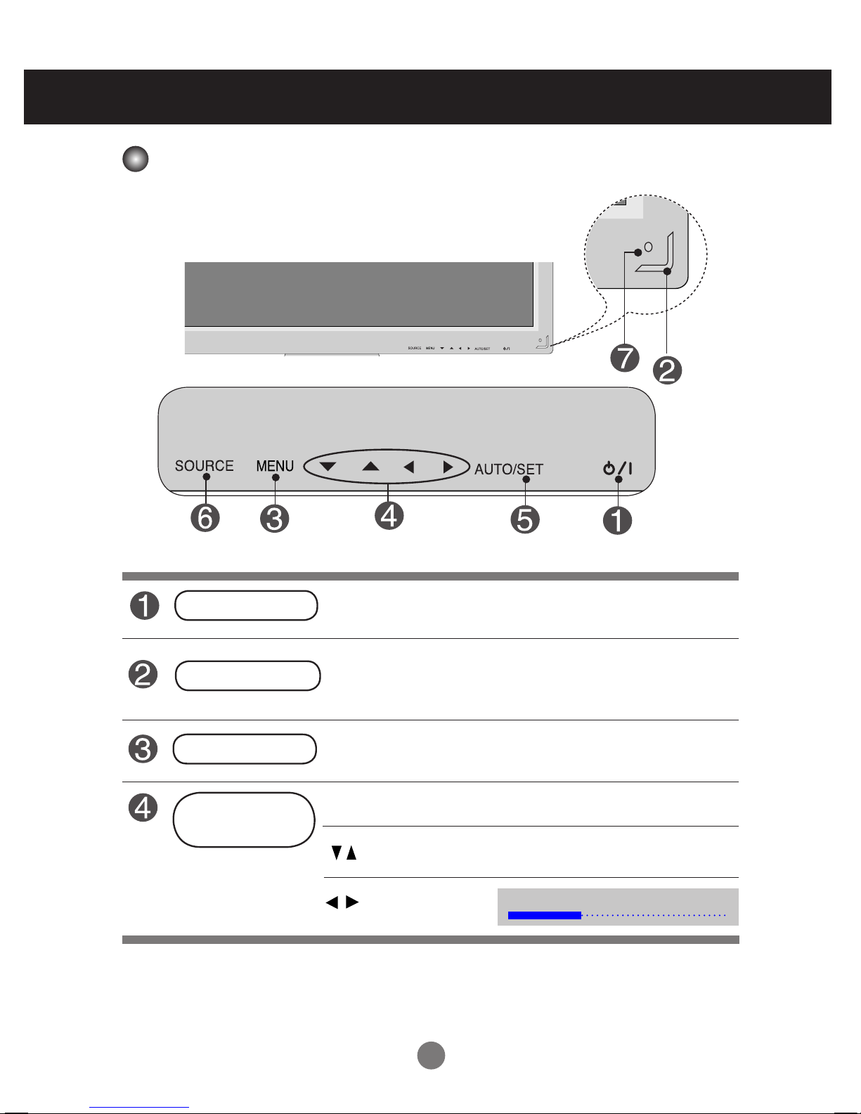
Screen Adjustment Options
• Press this button to turn on the power. Press this button again to
turn it off.
• This Indicator lights up blue when the display operates normally(on
mode). If the display is in sleep (Energy Saving) mode, this indicator
color changes to amber.
Power Button
• Adjust the volume.
• Adjust the up and down.
• Use this button to show/hide the OSD (On Screen Display).
MENU Button
• Use
this
button to select an icon or adjust the setting in the OSD.
OSD Select /
Adjust Button
Power Indicator
Volume
35
17
User Menus
• This is where the unit receives signals from the remote control.
Screen Adjustment Options
[For PC Analog signal]
AUTO/SET Button
AV Composite video, Separate video
RGB PC 15-pin D-Sub analog signal
HDMI/DVI Digital signal
- Toggles between inputs
SOURCE Button
IR Receiver
[When 1920 x 1080 is selected]
Input
AV
RGB PC
HDMI/DVI
▲▼
Auto in progress
For optimal display change
resolution to 1920 x 1080
Auto in progress
SOURCE
AUTO/SET
▼▲
18
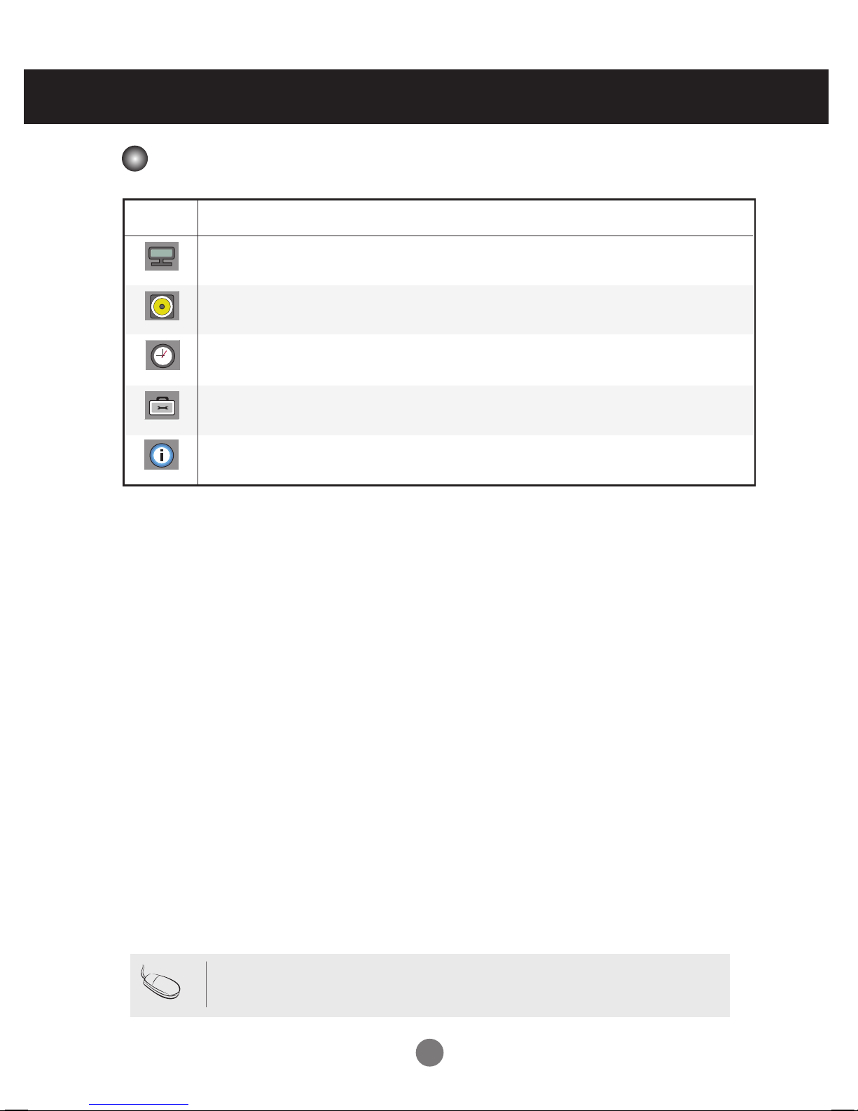
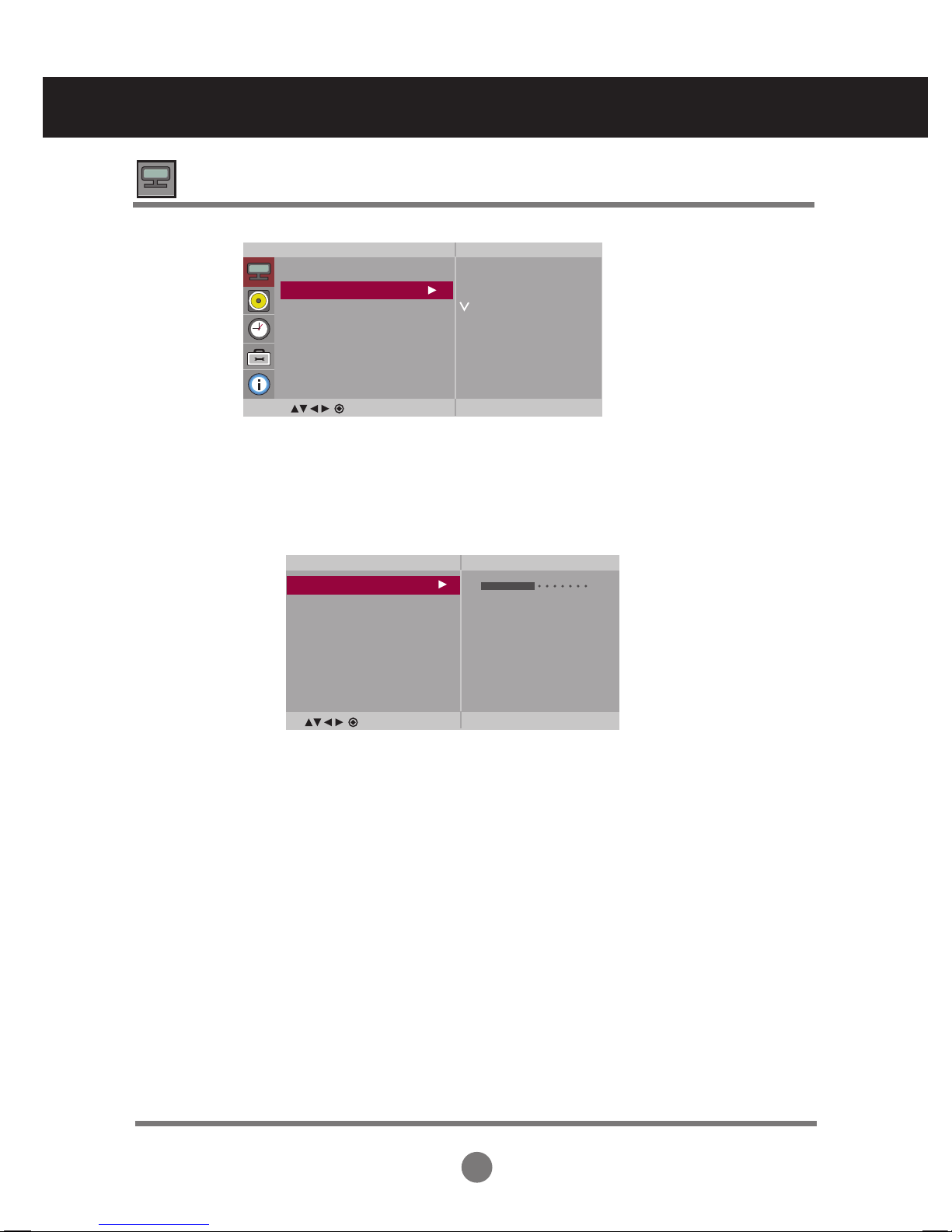
OSD Menu
Icon Function Description
Picture
Audio
Adjusts audio.
Adjusts screen brightness, contrast and color.
Note
OSD(On Screen Disp lay)
The OSD function enables you to conveniently adjust the screen status with a graphic
interface.
Option
Adjusts the screen status.
Time
Adjusts the timer options.
Information
Adjust ID and checks Serial No. and SW version.
User Menus
19
User Menus
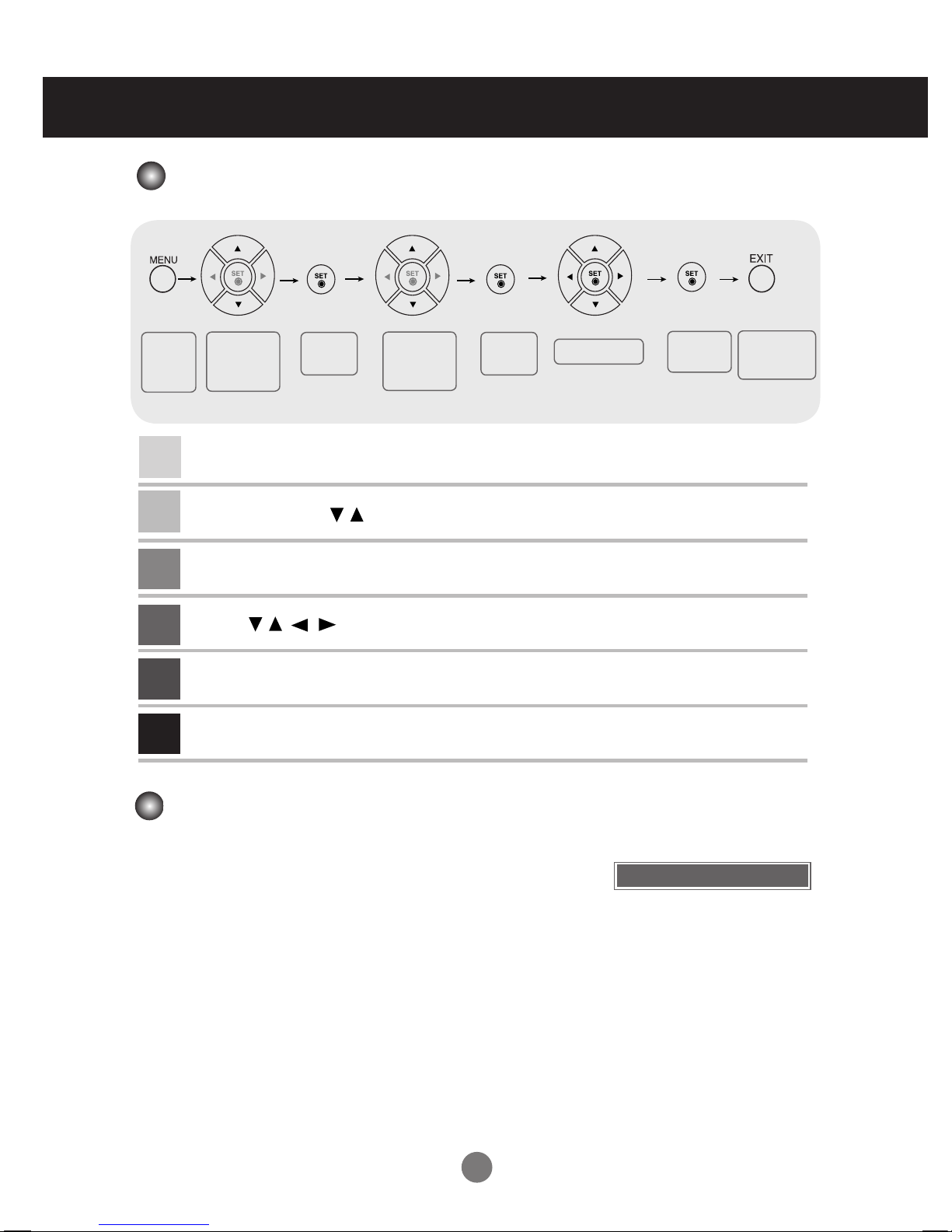
How to Adjust the OSD (On-Screen Display)
•
Use the remote control to adjust the OSD.
Adjusting the Screen Automatically
Press AUTO/SET (AUTO on the remote Control) when viewing a PC
analog signal. The optimal screen settings will be selected that suit the
current mode. If adjustments are not satisfactory, adjust the screen
manually.
Press the MENU button and the main menu of the OSD appears.
To navigate, use the Buttons.
When you've highlighted the desired icon, press SET.
Use the buttons to adjust the item.
Accept the changes by pressing SET.
Exit the OSD by pressing EXIT.
1
2
3
4
5
6
Pops up
the menu
screen
Move where
you want to
adjust
Move where
you want to
adjust
Select a
menu icon
Select a
menu icon
Adjust the status
Save
adjustment
Exit from the
menu screen.
[When 1920 x 1080 is selected]
Auto in progress
20
User Menus
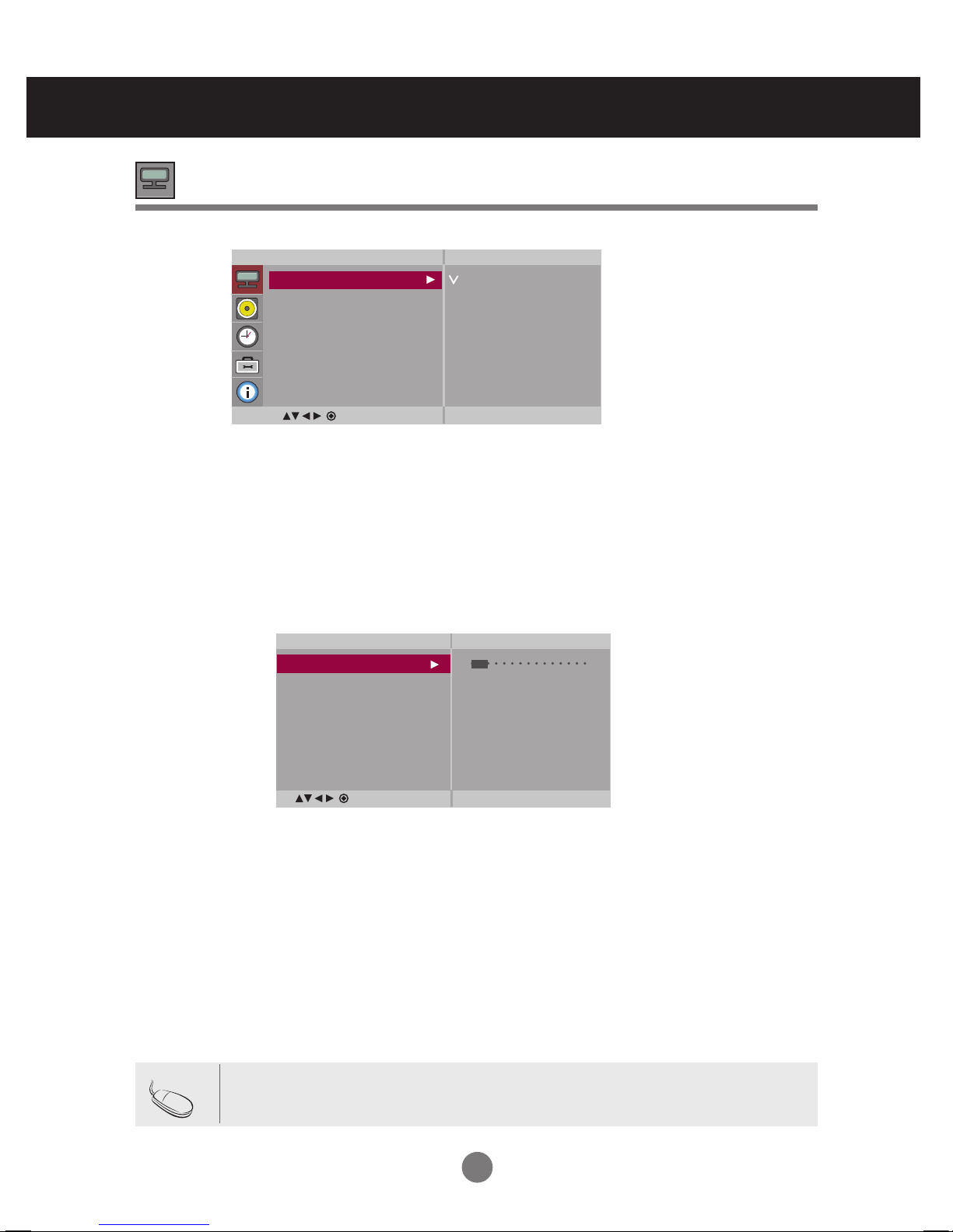
Adjusting Screen Color
Backlight : Adjusts the brightness of LCD panel.
Contrast : Adjusts the difference between light and dark levels.
Brightness : Adjusts the brightness of the screen.
Color : Adjusts the color (works in DTV mode).
Sharpness : Adjusts the clearness of the screen (function works in DTV mode).
Tint :Adjusts the tint (function works in DTV mode).
Expert : Compensates for each image mode, or adjusts image values according to a
particular image (applied only to User2 menu). (Function works in AV and HDMI-
DTV modes.)
Toggles between screen presets.
• Vivid : Displays a sharp image.
• Standard : This is the optimum viewing condition for general users.
• Cinema : This mode optimizes video for watching movies.
• Sport : This mode emphasizes dynamic video and primary colors (e.g. white, uniforms, grass,
sky blue, etc.) by realizing the optimal image settings for sports.
• Game : This is the mode for fast response speeds for video games.
• User1,2 : Select this option to use the user-defined settings.
Picture
Mode
Note
If the 'Picture Mode' setting in the Picture menu is set to Vivid, Standard, Cinema, Sport or
Game, the subsequent menus will be automatically set.
Picture
Picture Mode
Color Temperature
Advanced
Aspect Ratio
Picture Reset
Screen
Vivid
Standard
Cinema
Sport
Game
User1
User2
MENU
User2
Backlight 20
Contrast 90
Brightness 50
Color 50
Sharpness 50
Tint 50
Expert
MENU
21
User Menus
Red / Green / Blue
Set your own color levels.
Color Settings
• Cool : Slightly purple temperature.
• Medium : Slightly blue temperature.
• Warm : Slightly red temperature.
• User : Selects user-defined settings.
Color
Temperature
Picture
Picture Mode
Color Temperature
Advanced
Aspect Ratio
Picture Reset
Screen
Cool
Medium
Warm
User
Adjusting Screen Color
User
Red 0
Green 0
Blue 0
MENU
MENU
 Loading...