


Test Report No.: GETEC-E3-06-014
FCC Class B Certification
APPENDIX H
: USER’S MANUAL
EUT Type: 42” LCD Monitor
FCC ID: BEJM4201CE
A4
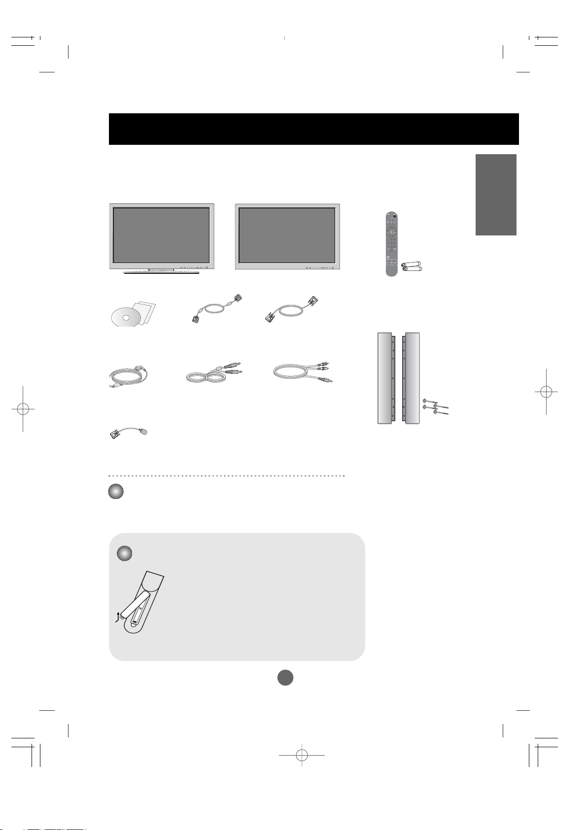
ENGLISH
Accessories
Speaker kit / Screws
(Applicable only for models
that support the speakers)
Remote Control/
Batteries
Power Cord
Audio Cable (PC)
Product
OR
Desktop Stand Type
Free Mount Type
Please check the accessories in the product package.
* The product and the accessories can be different from the figures shown here.
15-pin D-Sub Signal
Cable
DVI
Signal Cable
Wall-mount Rack
(This has to be purchased separately if required.)
Please refer to the enclosed "Installation Guide" when installing the wall-mount rack.
User's Guide/
Driver CD/Cards
1. Take out the battery cap.
2. Insert batteries with correct polarity (+/-).
3. Close the battery cap.
• You can use a remote Control 7 meter distance
and 30 degree (left/right) within the receiving unit
scope.
• Dispose of used batteries in the recycle bin to
prevent environmental pollution.
Inserting batteries into remote Control.
RCA-PC
Audio Cable
HDMI to DVI
Signal Cable
A5
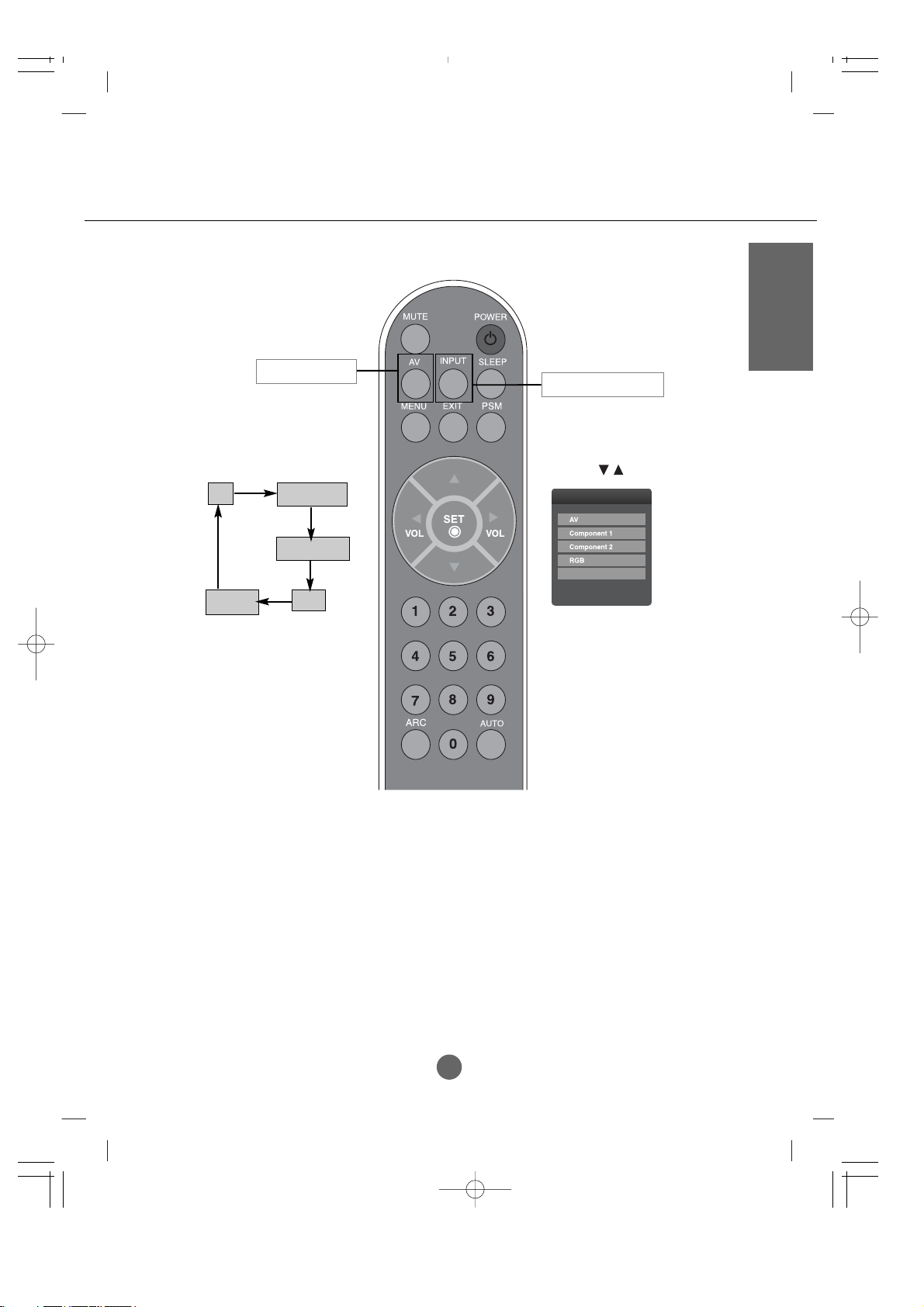
Using the Remote Control
Power On/Off Button
•
AV Button
•
Input Select Button
(See next page)
Sleep Button
When watching AV/S-Video/
Component1/ Component2
-
The product will be automatically turned off
after a certain period of time.
Press this button repetitively to select an
appropriate time duration
•
Menu Button
•
Exit Button
Auto Button
•
PC: Automatic adjustment function
(Operational for the analog signal only)
Check Button
Video Operation Button
Applicable for LG products only
Volume Button
Mute button
Name of the Remote Control Buttons
There is not a function
which is supported
PSM Button
- Automatically adjusts the image.
Press this button repetitively to set
the intended screen. (See A23)
•
PC :
Bring up and down direction
adjustment.
To select the image
size of the screen.
A6
ENGLISH
If you press the button once,
the following Input Signal
Window will appear. Select
the signal type you want
using the button.
•
Input Select Button
INPUT
HDMI/DVI
This button will be enabled
only when you selected the AV
signal. The signal type will be
changed with the following
order. Set the signal type you
want.
•
AV Button
AV
HDMI/DVI
RG B
Component 2
Component1
A7
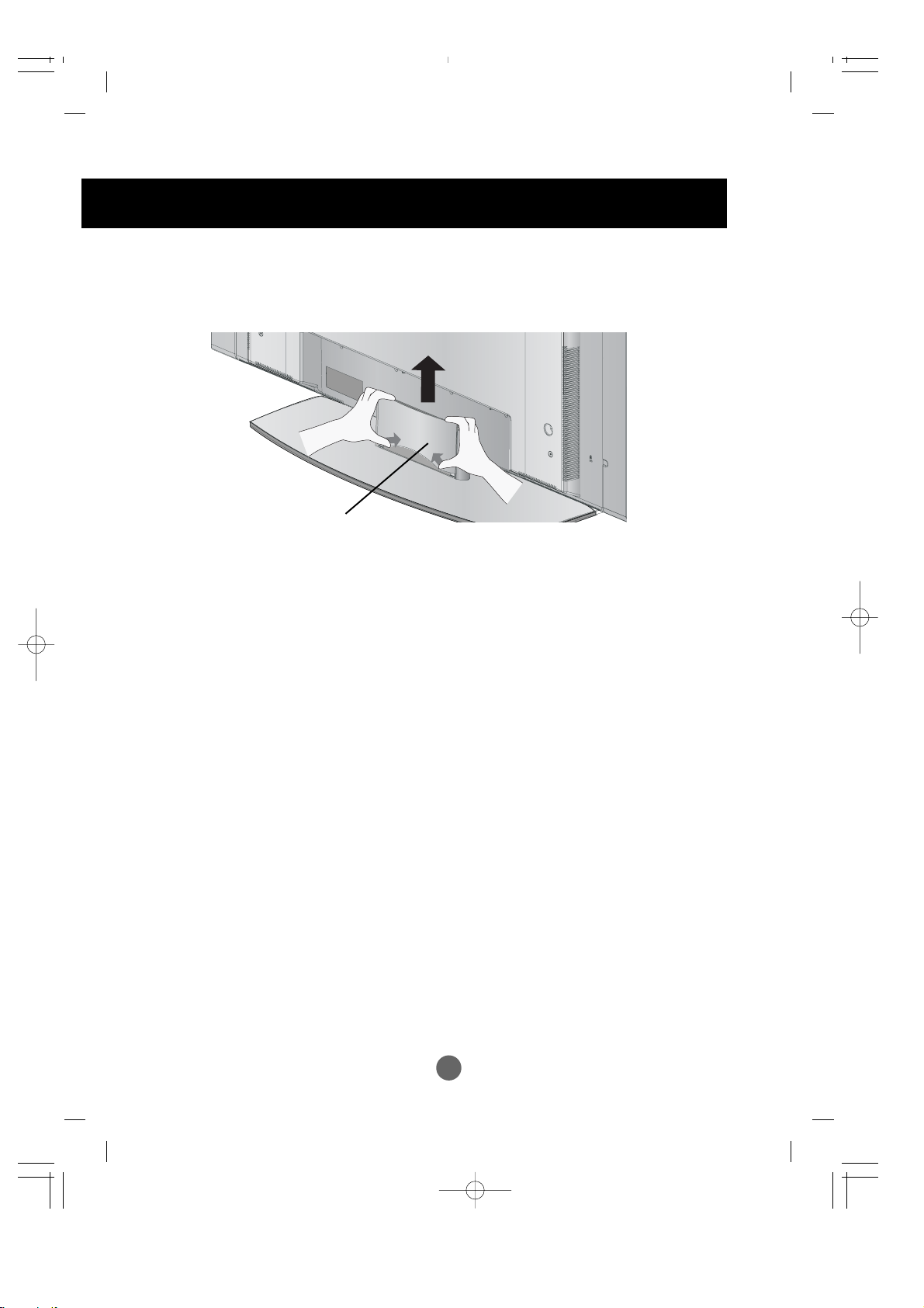
To arrange cables in order
1.
Disassemble the stand cover. The cover may be easily disassembled by pressing
down on the base as shown in the figure.
2.
After connecting the cables, correctly position the stand cover into the holes on the
stand. If securely connected, you will hear the latch click into place.
Stand cover
* Applicable only for models that support the stand
A8
ENGLISH
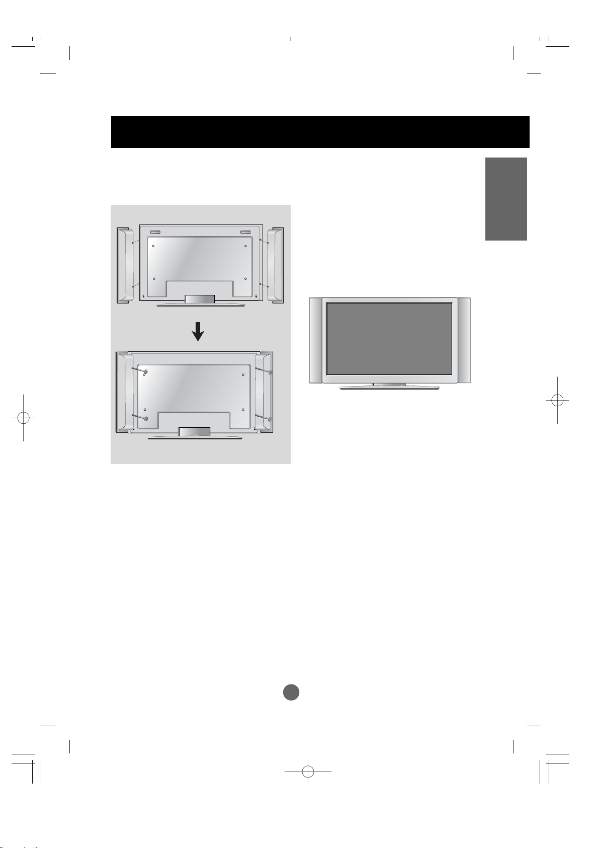
Connecting the Speakers
Use the screws to secure the speakers on the rear side of the product as shown
in the below figure.
* Applicable only for models that support the speakers
When the speaker is installed.
A9
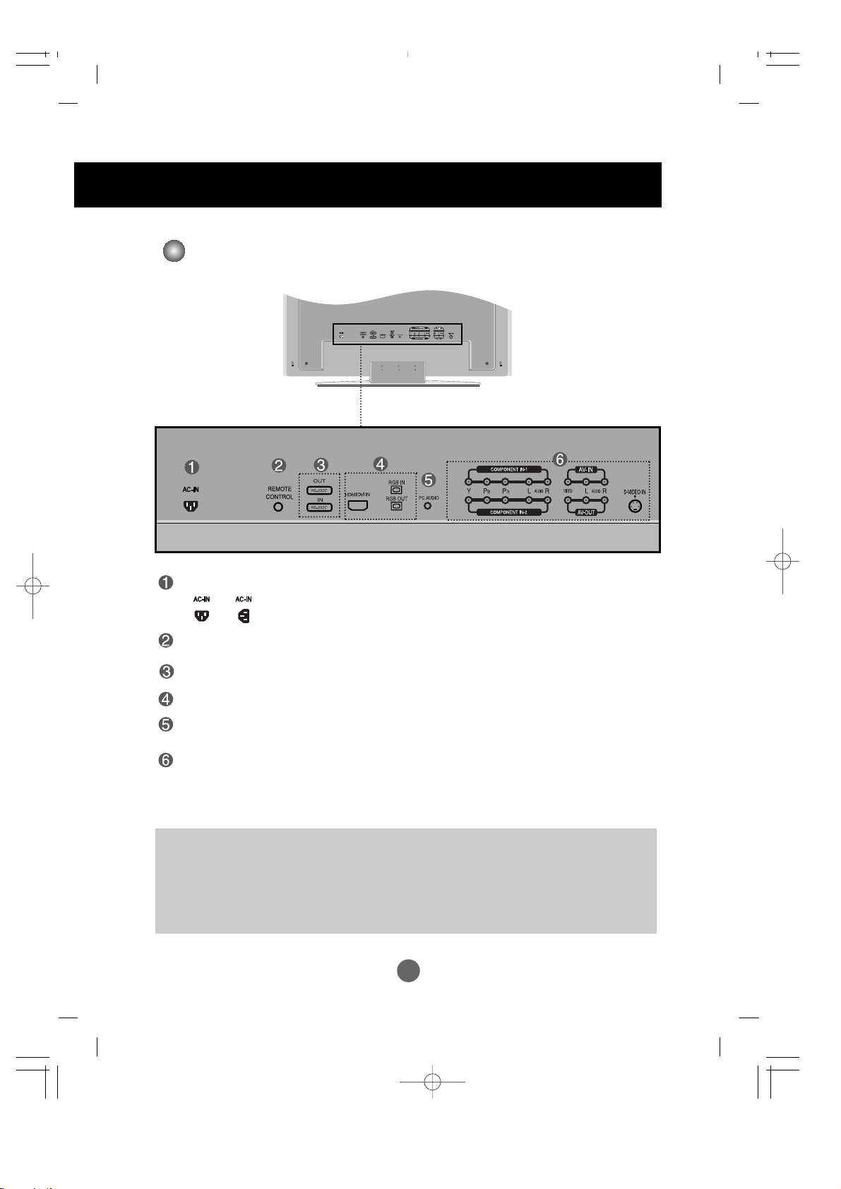
Name and Function of the Parts
Rear View
Power Connector : Connect the power cord
Power connector and image are different by product size.
Wired Remote Control Port
RS-232C Serial Ports
PC Signal Inputs
PC Sound Jack
: Connect the audio cable to the *LINE OUT jack of the PC sound card.
AV Ports
*LINE OUT
A terminal used to connect to the speaker including a built-in amplifier (Amp). Make sure that
the connecting terminal of the PC sound card is checked before connecting. If the Audio Out of
PC sound card has only Speaker Out, reduce the PC volume.
If the Audio Out of the PC sound card supports both Speaker Out and Line Out, convert to Line Out
using the card jumper of the program (Refer to the Sound Card Manual).
* The product image in the user’s guide could be different from the actual image.
A10
ENGLISH
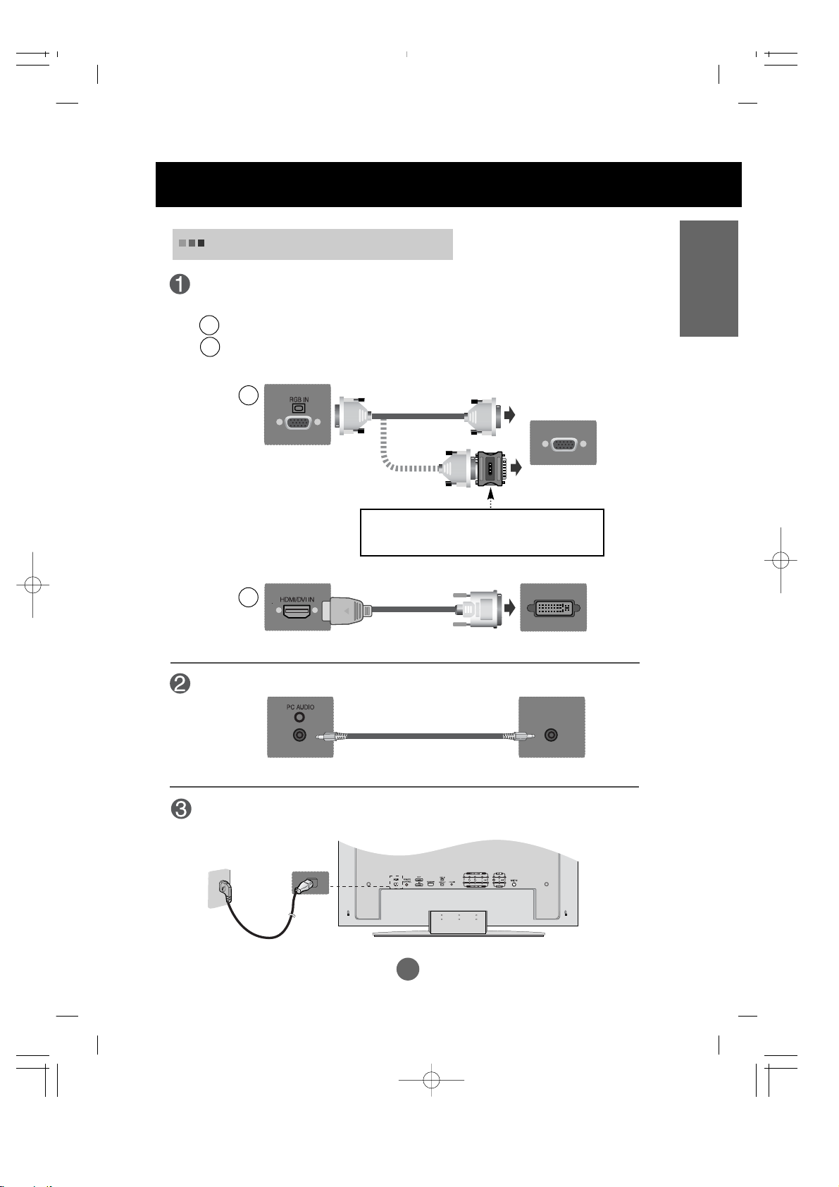
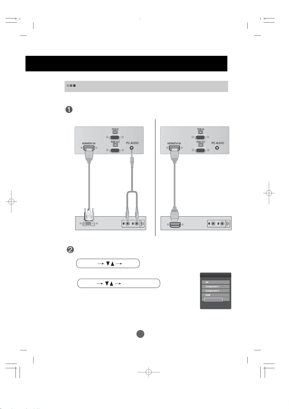
First of all, see if the computer, product and the peripherals are turned off.
Then, connect the signal input cable.
When connecting with the D-Sub signal input cable.
When connecting with the HDMI to DVI signal input cable.
MAC
Macintosh Adapter (not included)
Use the standard Macintosh adapter since an incompatible
adaptor is available in the market. (Different signaling system)
Rear side of the product.
* When connecting to a wall outlet.
Connecting to External Devices
Connect the power cord.
B
A
B
A
PC
When Connecting to your PC
PC/
MAC
PC
Rear side of the product.
Rear side of the product.
PC
Rear side of the product.
connect the Audio cable.
A11
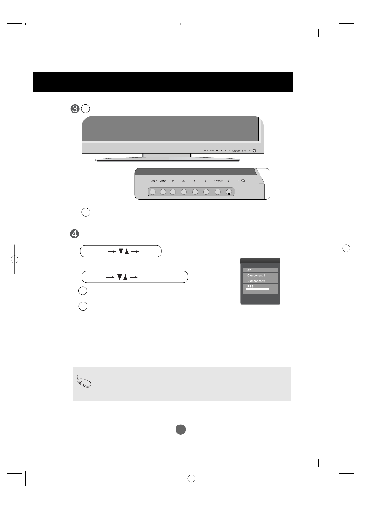
Select an input signal.
Press the INPUT button on the remote control to select the input signal.
Or, press the INPUT button at the front side of the product.
INPUT SET
•
How to connect to two computers.
Connect the signal cables (
HDMI to DVI
and D-Sub) to each computer.
Press the INPUT button in a remote control to select the computer to use.
•
Directly connect to a grounded power outlet on the wall or a power bar with a ground
wire.
Note
Turn on power by pressing the power button on the product.
Turn on the PC.
Power button
B
A
INPUT
HDMI/DVI
INPUT
AUTO/SET
When connecting with a D-Sub signal input cable.
• Select RGB : 15-pin
D-Sub
analog signal.
When connecting with a
HDMI to DVI
signal input cable.
• Select HDMI/DVI :
HDMI to DVI
Digital signal.
B
A
Connecting to External Devices
A12
ENGLISH
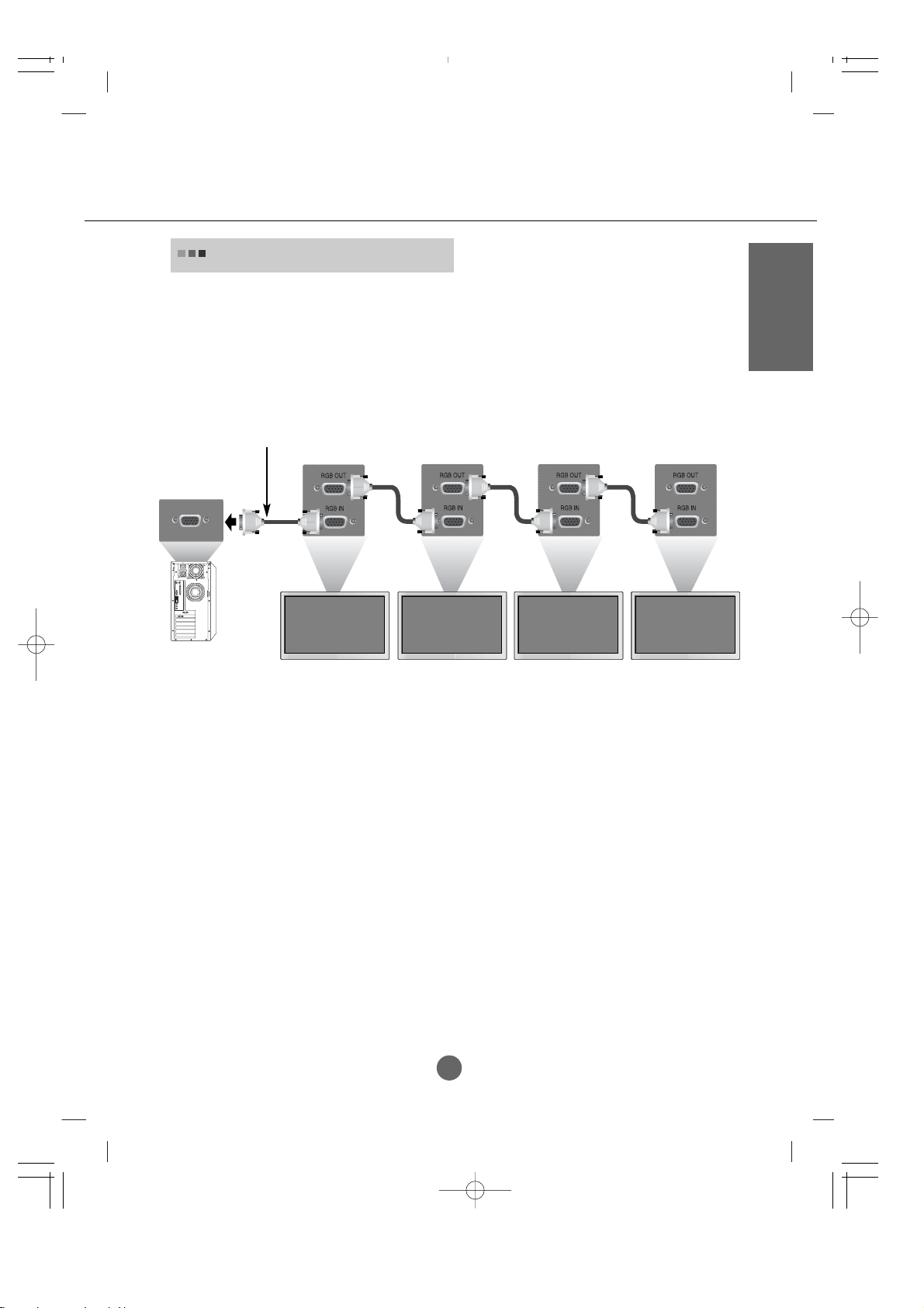
Use this function when displaying ANALOG RGB inputs of a PC to the other product.
Product 1
•
To use different products connected to each other
Connect one end of the signal input cable(15-pin D-Sub Signal Cable) to the RGB OUT
connector of product 1 and connect the other end to the RGB INPUT connector of other
products.
Watching RGB Outputs
PC
Product 2
Product 3
Product 4
15-pin D-Sub Signal Cable
A15
•
Select HDMI/DVI.
Connect the video/audio cable as shown in the below figure and then connect the
power cord (See page A11).
RCA-PC
Audio Cable
Product
VCR/DVD/Set-top Box
HDMI to DVI
Signal Cable
INPUT
HDMI/DVI
When watching
HDMI/DVI
from the VCR/DVD/Set-top Box
VCR/DVD/Set-top Box
Product
Select an input signal.
Press the INPUT button on the remote control to select the input signal.
Or, press the INPUT button at the front side of the product.
INPUT SET
INPUT
AUTO/SET
HDMI
Signal
Cable
Connecting to External Devices
 Loading...