

LG M2780D-PZ, M2380DB-PZ Owner's Manual

ENGLISH
OWNER’S MANUAL
LED LCD MONITOR TV
Please read this manual carefully before operating
your set and retain it for future reference.
LED LCD MONITOR TV MODELS
M2080D
M2280D
M2380D
M2780D
M2080DF
M2280DF
M2380DF
M2780DF
M2080DB
M2280DB
M2380DB
M2080DN
M2280DN
M2380DN
M2780DN
www.lg.com

CONTENTS
CONTENTS
PREPARATION
FRONT PANEL CONTROLS ..............................4
BACK PANEL INFORMATION ............................6
STAND INSTALLATION ......................................8
DETACHING STAND ........................................11
DETACHING STAND BODY .............................14
WALL MOUNT : HORIZONTAL INSTALLATION ....15
DESKTOP PEDESTAL INSTALLATION ...........16
POSITIONING YOUR DISPLAY .......................17
SWIVEL STAND(Only M2380D / M2380DF) ....17
LOCATION ........................................................17
KENSINGTON SECURITY SYSTEM ...............18
EXTERNAL EQUIPMENT SETUP
ANTENNA CONNECTION ................................19
HD RECEIVER SETUP ....................................20
DVD SETUP ......................................................23
VCR SETUP ......................................................26
INSERTION OF CI MODULE ...........................29
DIGITAL AUDIO OUT SETUP...........................30
USB SETUP ......................................................31
HEADPHONE SETUP ......................................32
OTHER A/V SOURCE SETUP .........................33
PC SETUP ........................................................34
BACK COVER FOR WIRE ARRANGEMENT ..37
SUPPORTED DISPALY RESOLUTION ...........38
WATCHING TV / PROGRAMME
CONTROL
REMOTE CONTROL KEY FUNCTIONS ..........40
TURNING ON THE TV .....................................42
PROGRAMME SELECTION .............................42
VOLUME ADJUSTMENT ..................................42
QUICK MENU ...................................................43
ON SCREEN MENUS SELECTION AND
ADJUSTMENT ..................................................44
AUTO PROGRAMME TUNING ........................45
CABLE DTV SETTING
(IN CABLE MODE ONLY) ..........................50
MANUAL PROGRAMME TUNING
(IN DIGITAL MODE) ...................................51
MANUAL PROGRAMME TUNING
(IN ANALOGUE MODE) .............................53
PROGRAMME EDIT .........................................55
IN DTV/RADIO MODE ......................................56
IN TV MODE .....................................................56
SOFTWARE UPDATE ......................................58
DIAGNOSTICS .................................................60
CI [COMMON INTERFACE] INFORMATION ...61
SELECTING THE PROGRAMME LIST ............62
FAVOURITE PROGRAMME SETUP ................63
INPUT LIST .......................................................64
EPG (ELECTRONIC PROGRAMME
GUIDE)(IN DIGITAL MODE)
Switch on/off EPG .............................................65
Select a programme ..........................................65
Button Function in NOW/NEXT Guide Mode ...66
Button Function in 8 Day Guide Mode .............66
Button Function in Date Change Mode ............67
Button Function in Extended Description Box ..67
Button Function in Record/Remind Setting Mode ...68
Button Function in Schedule List Mode ............68
PICTURE CONTROL
PICTURE SIZE (ASPECT RATIO) CONTROL .69
PICTURE WIZARD ...........................................71
ꕊ ENERGY SAVING .......................................72
PRESET PICTURE SETTINGS ........................73
MANUAL PICTURE ADJUSTMENT .................74
PICTURE IMPROVEMENT TECHNOLOGY ....75
EXPERT PICTURE CONTROL ........................76
PICTURE RESET .............................................79
SCREEN SETUP FOR PC MODE ...................80
SOUND CONTROL
AUTO VOLUME LEVELER ...............................85
CLEAR VOICE II ...............................................86
BALANCE ..........................................................87
PRESET SOUND SETTINGS-SOUND MODE ...88
PRESET SOUND SETTINGS-USER MODE ...89
2

Surround X ........................................................89
AUDIO RESET ..................................................90
DIGITAL AUDIO OUT ........................................91
TV SPEAKERS ON / OFF SETUP ...................92
DTV AUDIO SETTING
(IN DIGITAL MODE ONLY) ........................93
I/II
Stereo/Dual Reception
(In Analogue Mode Only) .....................94
NICAM Reception
(In Analogue Mode Only) .....................95
Speaker Sound Output Selection ...............95
TIME SETTING
CLOCK SETUP .................................................96
AUTO ON/OFF TIME SETTING .......................97
SLEEP TIMER SETTING ..................................98
TO USE A USB DEVICE
WHEN CONNECTING A USB DEVICE..........113
PHOTO LIST ...................................................115
MUSIC LIST ....................................................121
MOVIE LIST ....................................................125
DIVX REGISTRATION CODE ........................132
DEACTIVATION ..............................................133
TELETEXT
SWITCH ON/OFF ...........................................134
SIMPLE TEXT .................................................134
TOP TEXT .......................................................134
FASTEXT ........................................................135
SPECIAL TELETEXT FUNCTION ..................135
DIGITAL TELETEXT
CONTENTS
OPTION SETTING
ON-SCREEN MENU LANGUAGE / COUNTRY
SELECTION ......................................................99
LANGUAGE SELECTION
(IN DIGITAL MODE ONLY) ......................100
AUDIO DESCRIPTION
(IN DIGITAL MODE ONLY) ......................101
DATA SERVICE ...............................................102
INPUT LABEL .................................................103
POWER INDICATOR ......................................104
DEMO MODE ..................................................105
MODE SETTING .............................................106
INITIALIZING(RESET TO ORIGINAL FACTORY
SETTINGS) .........................................................107
PARENTAL CONTROL / RATINGS
SET PASSWORD & LOCK SYSTEM .............108
BLOCK PROGRAMME ...................................109
PARENTAL CONTROL
(IN DIGITAL MODE ONLY) ......................110
INPUT BLOCK ................................................ 111
KEY LOCK ......................................................112
TELETEXT WITHIN DIGITAL SERVICE ........136
TELETEXT IN DIGITAL SERVICE ..................136
APPENDIX
TROUBLESHOOTING ....................................137
MAINTENANCE ..............................................141
PRODUCT SPECIFICATIONS .......................142
PROGRAMMING THE REMOTE CONTROL 146
PROGRAMMING CODE .................................146
IR CODES .......................................................148
EXTERNAL CONTROL DEVICE SETUP
RS-232C Setup ........................................149
Type of Connector; D-Sub 9-Pin Male .....149
RS-232C Configurations ..........................149
Set ID ........................................................150
Communication Parameters .....................151
3
PREPARATION
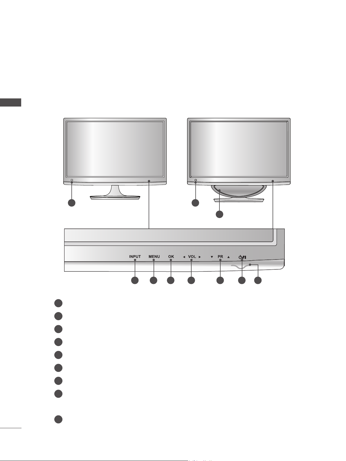
FRONT PANEL CONTROLS
■ This is a simplified representation of the front panel. The image shown may be somewhat different
from your set.
PREPARATION
M2080D / M2280D
M2380D / M2780D
1 1
M2080DF / M2280DF
M2380DF / M2780DF
9
2 3 4 5 6 7 8
IR receiver (Remote controller receiver)
1
INPUT Button
2
MENU Button
3
OK Button
4
VOLUME Button
5
PROGRAMME Button
6
7
Power Button
Power Indicator
8
Illuminates blue when the set is switched on.
Note: You can adjust Power indicator in the OPTION menu.
9
WOOFER
4
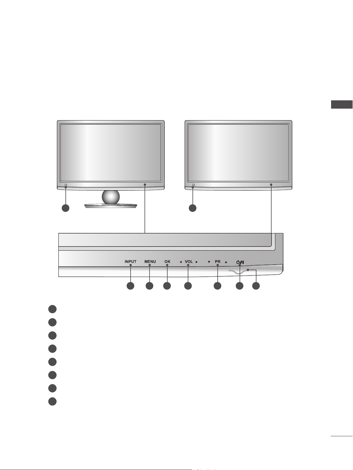
FRONT PANEL CONTROLS
■ This is a simplified representation of the front panel. The image shown may be somewhat different
from your set.
M2080DB / M2280DB
M2380DB
1 1
M2080DN / M2280DN
M2380DN / M2780DN
PREPARATION
2
IR receiver (Remote controller receiver)
1
INPUT Button
2
MENU Button
3
OK Button
4
VOLUME Button
5
PROGRAMME Button
6
7
Power Button
Power Indicator
8
Illuminates blue when the set is switched on.
Note: You can adjust Power indicator in the OPTION menu.
3 4 5 6 7 8
5
PREPARATION
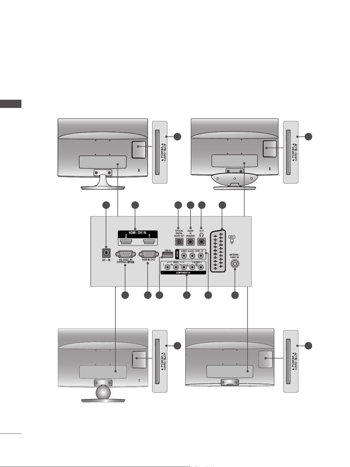
BACK PANEL INFORMATION
■ This is a simplified representation of the back panel. The image shown may be somewhat different
from your set.
PREPARATION
M2080D / M2280D
M2380D / M2780D
1
M2080DF / M2280DF
M2380DF / M2780DF
13
2 3 4 5 6
13
7 8 9
M2080DB / M2280DB
M2380DB
10 11 12
13 13
M2080DN / M2280DN
M2380DN / M2780DN
6

BACK PANEL INFORMATION
DC ADAPTER PORT
1
Connect to the power cord socket.
2
HDMI / DVI INPUT
Connect a HDMI signal to HDMI IN.
Or DVI (VIDEO) signal to HDMI IN with DVI to HDMI cable.
OPTICAL DIGITAL AUDIO OUT
3
Connect digital audio to various types of equipment. Connect to a Digital Audio Component.
Use an Optical audio cable.
RGB/DVI AUDIO INPUT
4
Connect the audio from a PC.
HEADPHONE SOCKET
5
Plug the headphone into the headphone socket.
6
Euro Scart Socket (AV1)
Connect scart socket input or output from an external device to these jacks.
PREPARATION
7
RS-232C IN (CONTROL & SERVICE) PORT
Connect to the RS-232C port on a PC.
This port is used for Service or Hotel mode.
RGB INPUT (PC)
8
Connect the output from a PC.
9
USB Input
10
COMPONENT INPUT
Connect a component video/audio device to these jacks.
11
AV2 (AUDIO/VIDEO) INPUT
Connect audio/video output from an external device to these jacks.
12
ANTENNA / CABLE INPUT
Connect over-the-air signals to this jack.
13
PCMCIA (PERSONAL COMPUTER MEMORY CARD INTERNATIONAL ASSOCIATION) CARD SLOT
Insert the CI Module to PCMCIA CARD SLOT.
(This feature is not available in all countries.)
7
PREPARATION
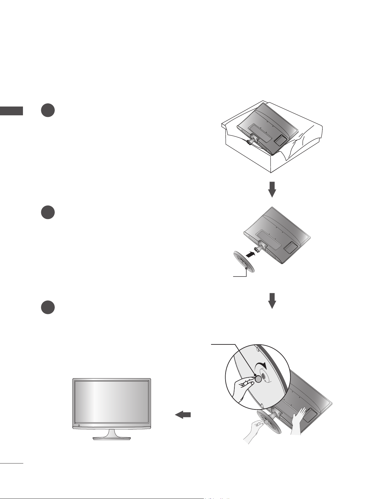
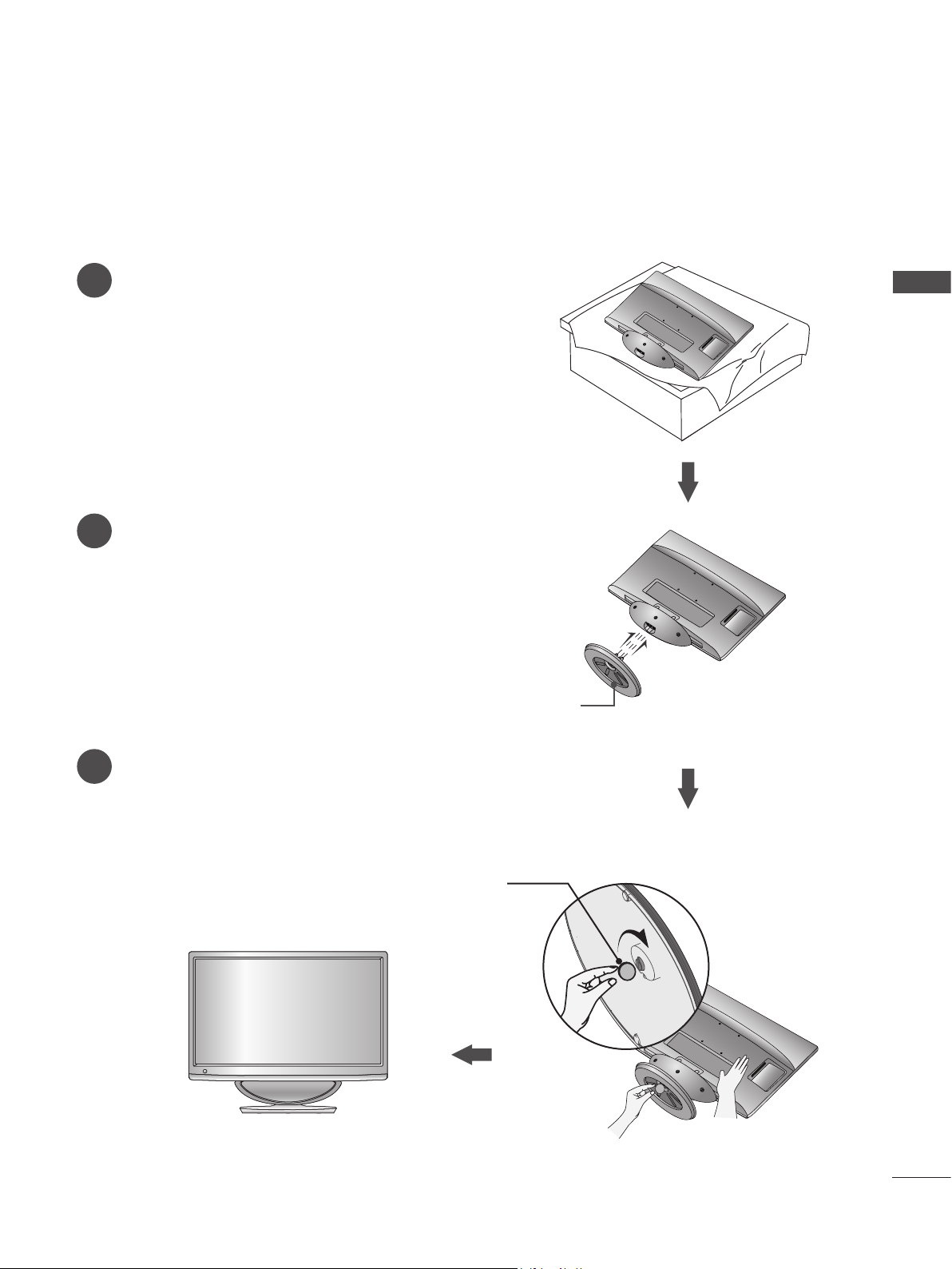
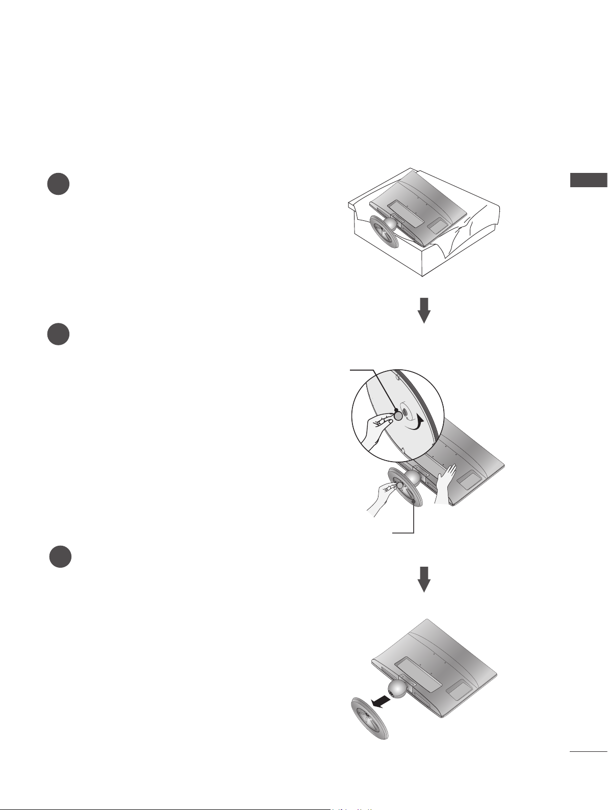
STAND INSTALLATION
■ The image shown may be somewhat different from your set.
Carefully place the product screen side down on a
1
PREPARATION
cushioned surface that will protect product and
screen from damage.
Insert the Stand Base into the product.
2
M2080D/M2280D/M2380D/M2780D
Use a Coin on the bottom of the stand base
3
and turn the screw clockwise to tighten.
Stand Base
Coin
8
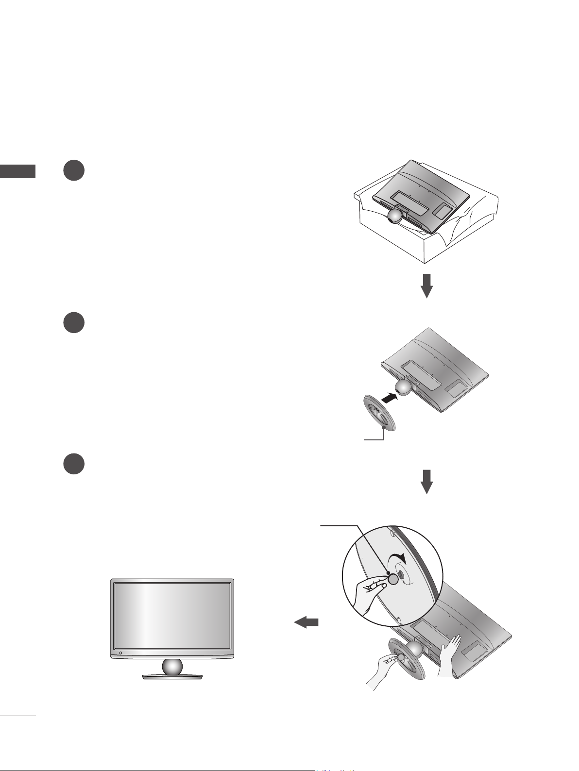
M2080DF/M2280DF/M2380DF/M2780DF
STAND INSTALLATION
■ The image shown may be somewhat different from your set.
Carefully place the product screen side down on a
1
cushioned surface that will protect product and
screen from damage.
Insert the Stand Base into the product.
2
PREPARATION
Use a Coin on the bottom of the stand base
3
and turn the screw clockwise to tighten.
Stand Base
Coin
9
PREPARATION
STAND INSTALLATION
■ The image shown may be somewhat different from your set.
Carefully place the product screen side down on a
1
PREPARATION
cushioned surface that will protect product and
screen from damage.
Insert the Stand Base into the product.
2
M2080DB/M2280DB/M2380DB
Use a Coin on the bottom of the stand base
3
and turn the screw clockwise to tighten.
Stand Base
Coin
10
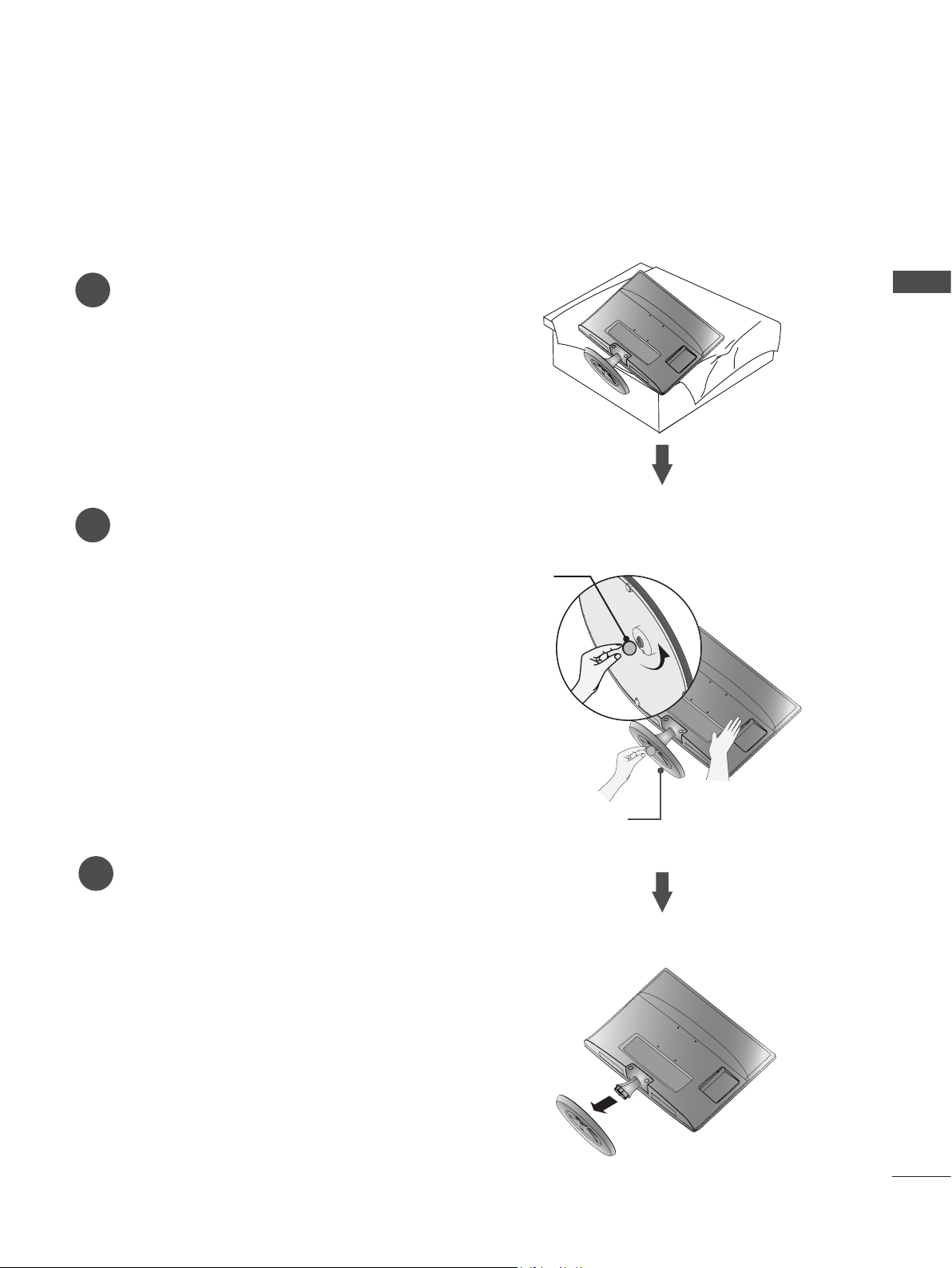
M2080D/M2280D/M2380D/M2780D
DETACHING STAND
■ The image shown may be somewhat different from your set.
Place the set screen side down on a cushion
1
or soft cloth.
Detach the monitor to the Stand Base by turn-
2
ing the screw to the left.
Turn the screw by using a Coin.
PREPARATION
Coin
Pull the stand base.
3
Stand Base
11
PREPARATION
DETACHING STAND
■ The image shown may be somewhat different from your set.
Place the set screen side down on a cushion
PREPARATION
1
or soft cloth.
Detach the monitor to the Stand Base by turn-
2
ing the screw to the left.
Turn the screw by using a Coin.
M2080DF/M2280DF/M2380DF/M2780DF
Coin
12
Pull the stand base.
3
Stand Base
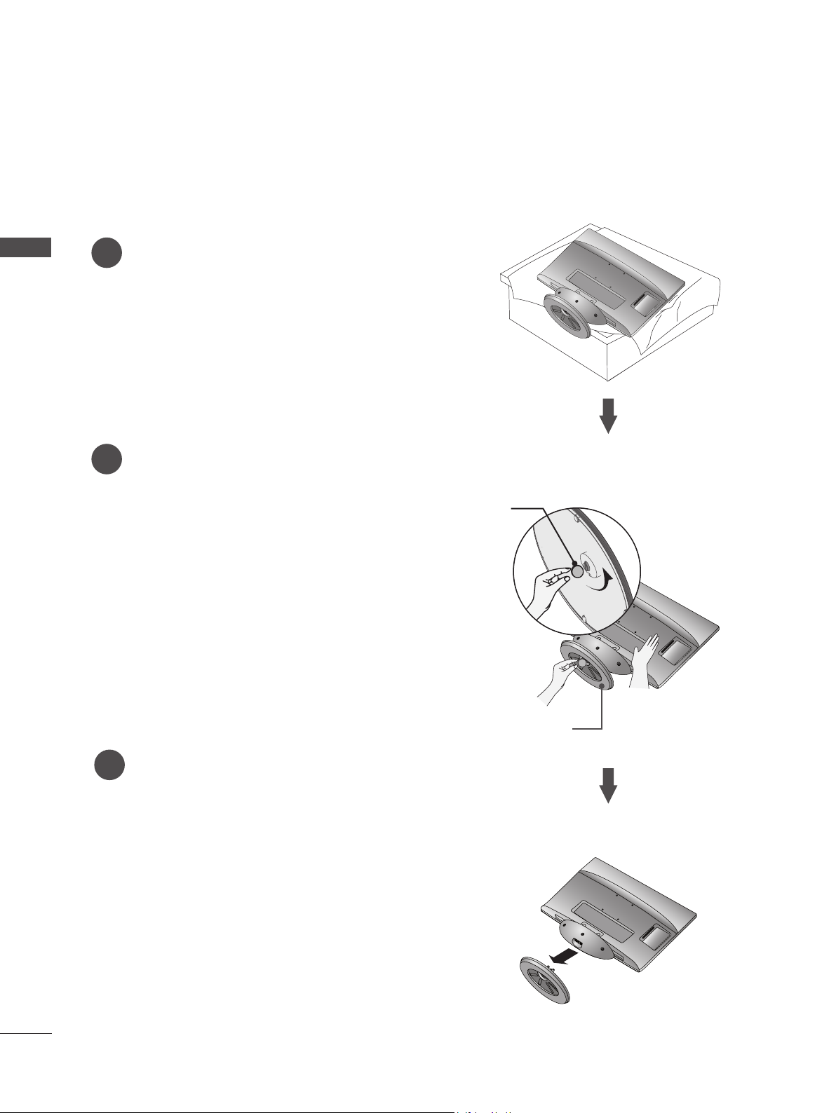
M2080DB/M2280DB/M2380DB
DETACHING STAND
■ The image shown may be somewhat different from your set.
Place the set screen side down on a cushion
1
or soft cloth.
Detach the monitor to the Stand Base by turn-
2
ing the screw to the left.
Turn the screw by using a Coin.
Coin
PREPARATION
Pull the stand base.
3
Stand Base
13
PREPARATION
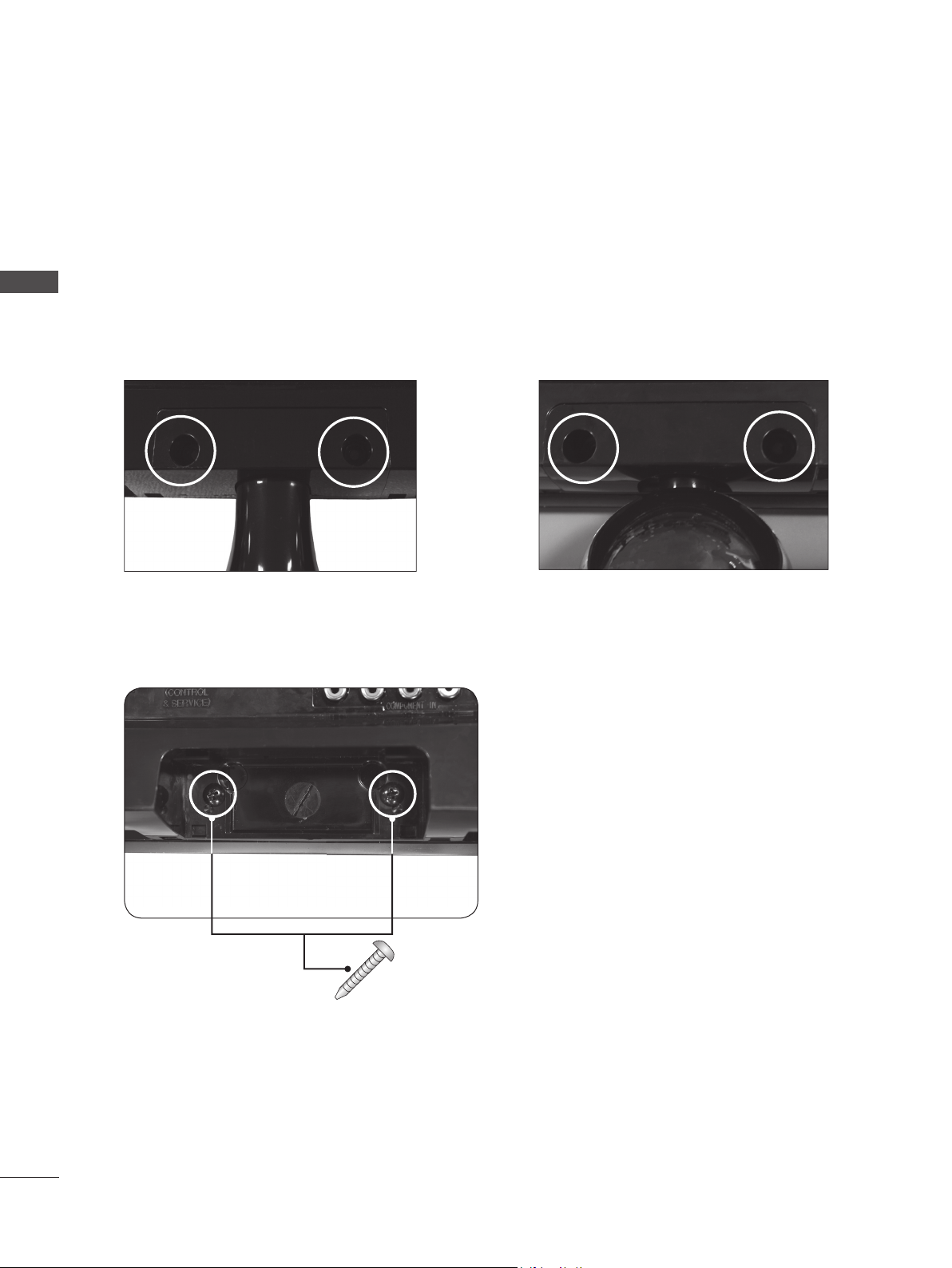
DETACHING STAND BODY
■ The image shown may be somewhat different from your set.
■ Remove the Stand Body in the same way as the following when using it as a Wall Hook.
PREPARATION
1. Remove the screw 2 point.
2. Pull the stand body.
M2080D / M2280D
M2380D / M2780D
3. Assemble the screw 2 point
M2080DB / M2280DB
M2380DB
14
Screw
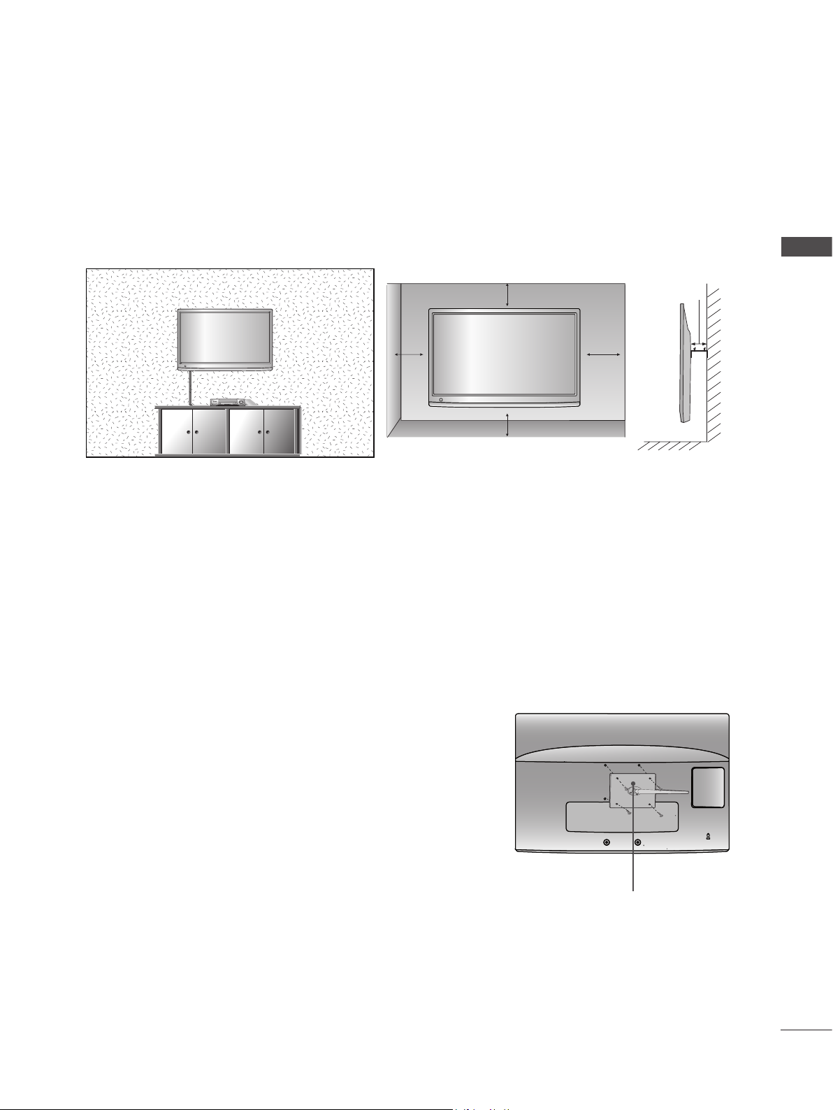
WALL MOUNT : HORIZONTAL INSTALLATION
For proper ventilation, allow a clearance of 10 cm on each side and from the wall. Detailed installation
instructions are available from your dealer, see the optional Tilt Wall Mounting Bracket Installation and
Setup Guide.
PREPARATION
10 cm
10 cm
10 cm
10 cm
10 cm
If you intend to mount the set to a wall, attach Wall mounting interface (optional parts) to the back of the set.
When you install the set using the wall mounting interface (optional parts), attach it carefully so it will not drop.
1. Be sure to use screws and a wall mount that meet VESA standards.
2. Using screws longer than those recommended might damage the product.
3. Using screws that do not meet VESA standards might either damage the product or result in it coming
away from the wall. We will not be held responsible for any damage resulting from failure to follow these
instructions.
4. VESA compatible only with respect to screw mounting interface dimensions and mounting screw specifications
5. Please use VESA standard as below.
5-1) 784.8 mm (30.9 inch) and under
* Wall Mount Pad Thickness : 2.6 mm
* Screw : Φ 4.0 mm x Pitch 0.7 mm x Length 10 mm
5-2) 787.4 mm (31.0 inch) and above
* Please use VESA standard wall mount pad and screws.
< Screw Mounting Interface Dimension >
● M2080D / M2280D / M2380D: 75 mm x 75 mm hole spacing
● M2080DF / M2280DF / M2380DF: 75 mm x 75 mm hole spacing
● M2080DB / M2280DB / M2380DB: 75 mm x 75 mm hole spacing
● M2080DN / M2280DN / M2380DN: 75 mm x 75 mm hole spacing
● M2780D / M2780DF / M2780DN: 100 mm x 200 mm hole spacing
Wall Mount Pad
15
PREPARATION
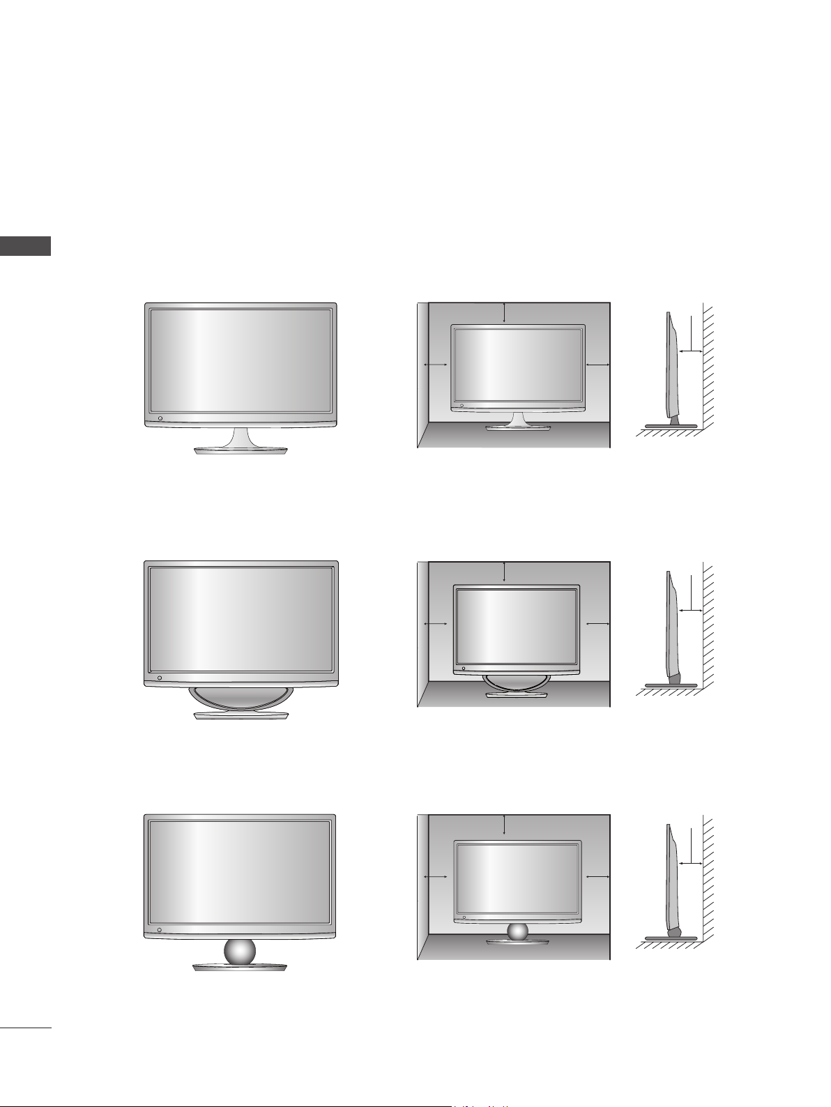
DESKTOP PEDESTAL INSTALLATION
■ The image shown may be somewhat different from your set.
For proper ventilation, allow a clearance of 10 cm on each side and from the wall.
PREPARATION
M2080D / M2280D
M2380D / M2780D
M2080DF / M2280DF
M2380DF / M2780DF
10 cm
10 cm
10 cm
10 cm
10 cm
10 cm
10 cm
10 cm
16
M2080DB / M2280DB
M2380DB
10 cm
10 cm
10 cm
10 cm
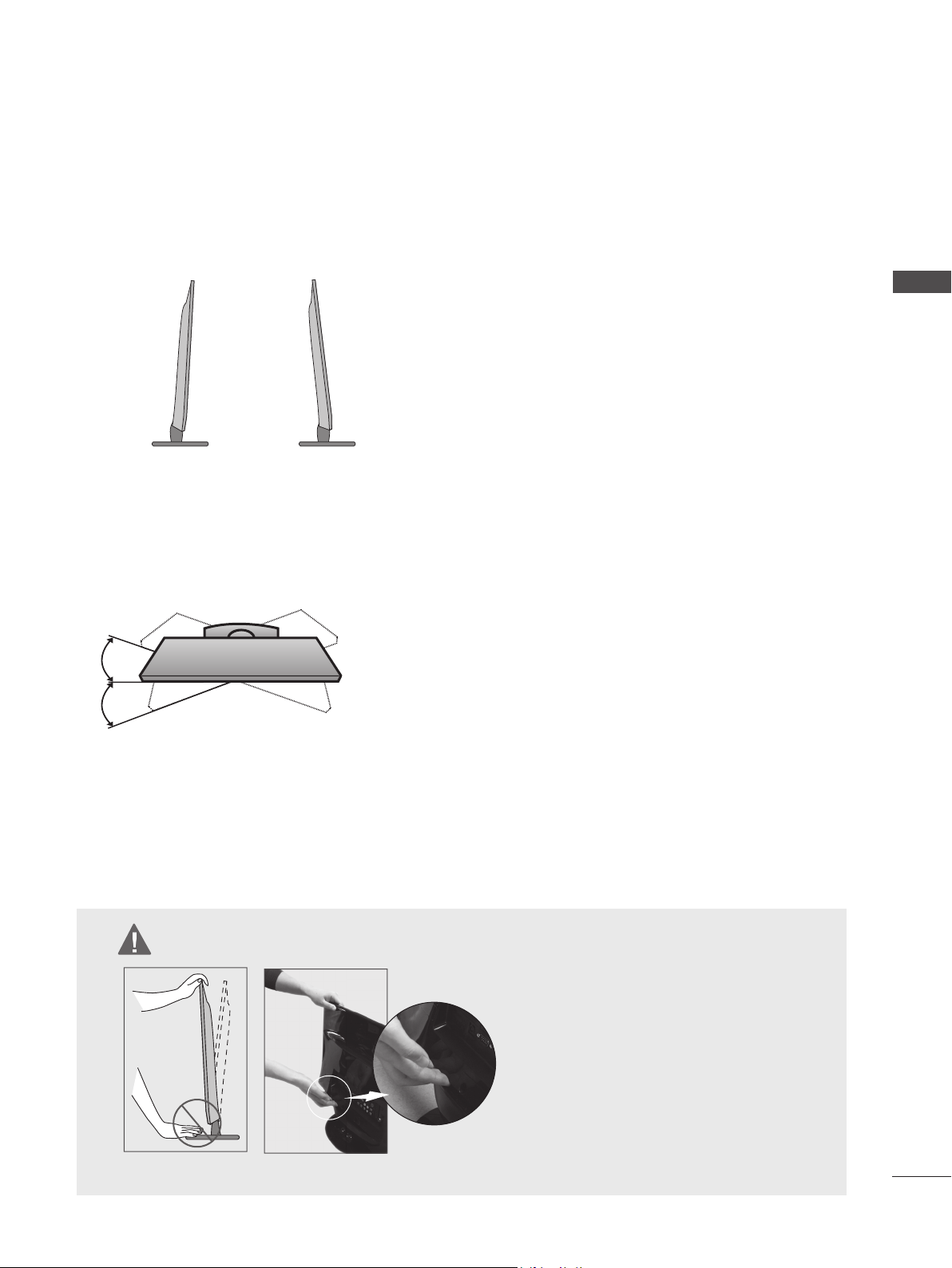
POSITIONING YOUR DISPLAY
■ The image shown may be somewhat different from your set.
* Tilt range
-5° 10°
Adjust the position of the panel in various ways for maximum
comfort.
SWIVEL STAND(Only M2780D / M2780DF)
■ The image shown may be somewhat different from your set.
After installing the set, you can adjust the set manually to the
left or right direction by 179 degrees to suit your viewing position.
PREPARATION
LOCATION
Position your set so that no bright light or sunlight falls directly onto the screen. Care should be taken not to
expose the set to any unnecessary vibration, moisture, dust or heat. Also, ensure that the set is placed in a
position to allow a free flow of air. Do not cover the ventilation openings on the back cover.
WARNING
■ When adjusting the angle of the screen,
do not put your finger(s) in between the
head of the monitor and the stand body
or woofer.
You can hurt your finger(s).
M2080DF / M2280DF / M2380DF / M2780DF
17
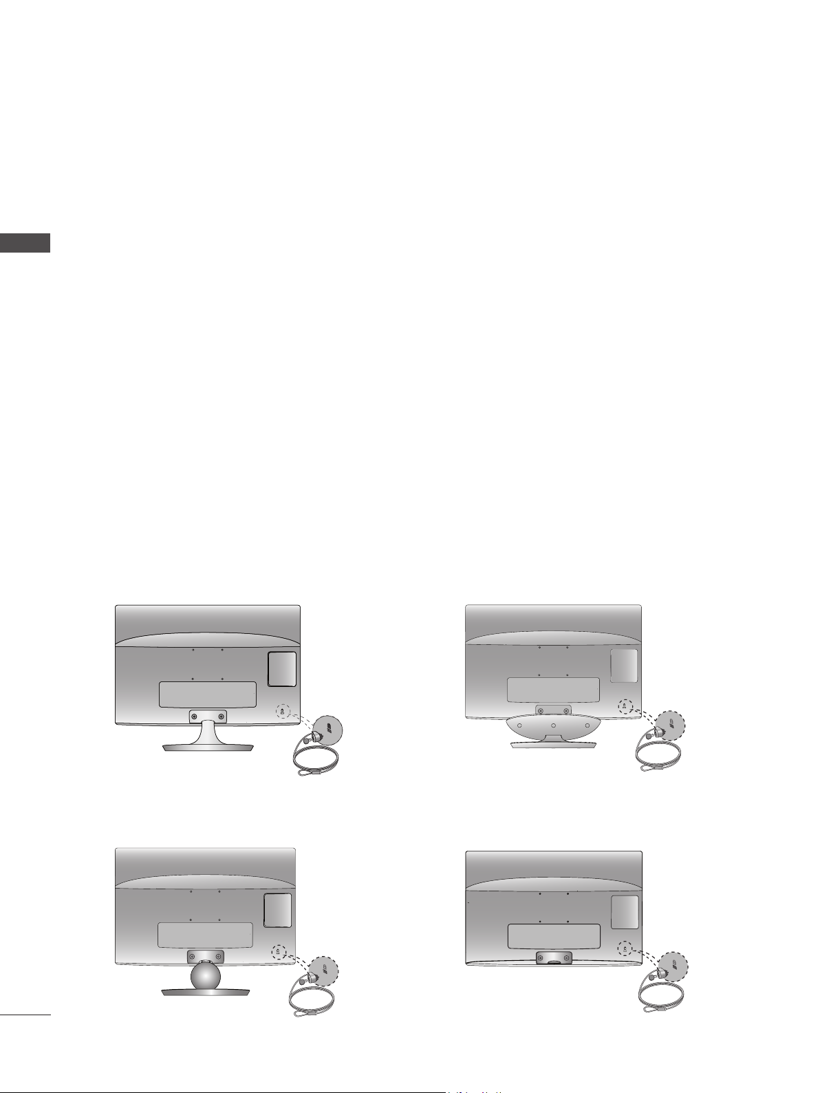
PREPARATION
KENSINGTON SECURITY SYSTEM
- The product is equipped with a Kensington Security System connector on the back panel. Connect the
Kensington Security System cable as shown below.
- For detailed installation and use of the Kensington Security System, refer to the user’s guide provided
PREPARATION
with the Kensington Security System.
For further information, contact http://www.kensington.com, the internet homepage of the Kensington
company. Kensington sells security systems for expensive electronic equipment such as notebook
PCs and LCD projectors.
NOTE
- The Kensington Security System is an optional accessory.
NOTES
a. If the product feels cold to the touch, there may be a small “flicker” when it is turned on.
This is normal, there is nothing wrong with product.
b. Some minute dot defects may be visible on the screen, appearing as tiny red, green, or blue spots.
However, they have no adverse effect on the monitor’s performance.
c. Avoid touching the LCD screen or holding your finger(s) against it for long periods of time.
Doing so may produce some temporary distortion effects on the screen.
M2080D / M2280D
M2380D / M2780D
M2080DB / M2280DB
M2380DB
M2080DF / M2280DF
M2380DF / M2780DF
M2080DN / M2280DN
M2380DN / M2780DN
18
EXTERNAL EQUIPMENT SETUP
■ To prevent damage do not connect to the mains outlet until all connections are made between the devices.
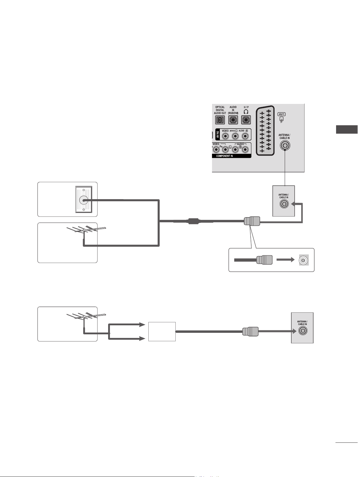
ANTENNA CONNECTION
■ For optimum picture quality, adjust antenna direction.
■ An antenna cable and converter are not supplied.
Multi-family Dwellings / Apartments
Wall
Antenna
Socket
(Connect to wall antenna socket)
EXTERNAL EQUIPMENT SETUP
RF Coaxial Wire (75 Ω)
Outdoor
Antenna
Antenna
■ In poor signal areas, to get better picture quality, install a signal amplifier to the antenna as shown above.
■ If signal needs to be split for two sets, use an antenna signal splitter for connection.
Single-family Dwellings / Houses
(Connect to wall jack for outdoor antenna)
UHF
Signal
Amplifier
VHF
19
EXTERNAL EQUIPMENT SETUP
■ To avoid damaging any equipment, never plug in any power cords until you have finished connecting all equipment.
■ The image shown may be somewhat different from your set.
HD RECEIVER SETUP
Connecting with a component cable
Connect the video outputs (Y, PB, PR) of the digital
EXTERNAL EQUIPMENT SETUP
1
set-top box to the COMPONENT IN VIDEO jacks on
the SET.
Connect the audio output of the digital set-top box
2
to the COMPONENT IN AUDIO jacks on the SET.
Turn on the digital set-top box.
3
(Refer to the owner’s manual for the digital set-top
box.)
Select COMPONENT input source using the INPUT
4
button on the remote control
► HDMI Audio Supported format : Dolby Digital, PCM
DTS Audio format is not supported.
Signal Component HDMI
480i / 576i YES No
480p / 576p YES YES
720p / 1080i YES YES
1080p
(50 Hz / 60Hz only)
YES
(24 Hz / 30 Hz / 50Hz / 60Hz)
YES
1
2
20
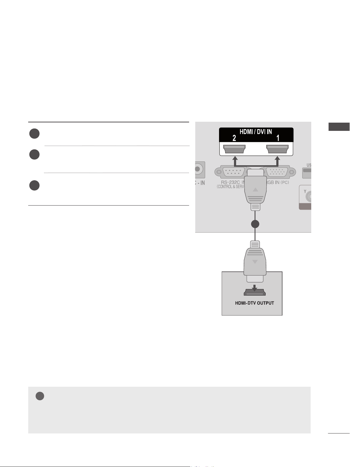
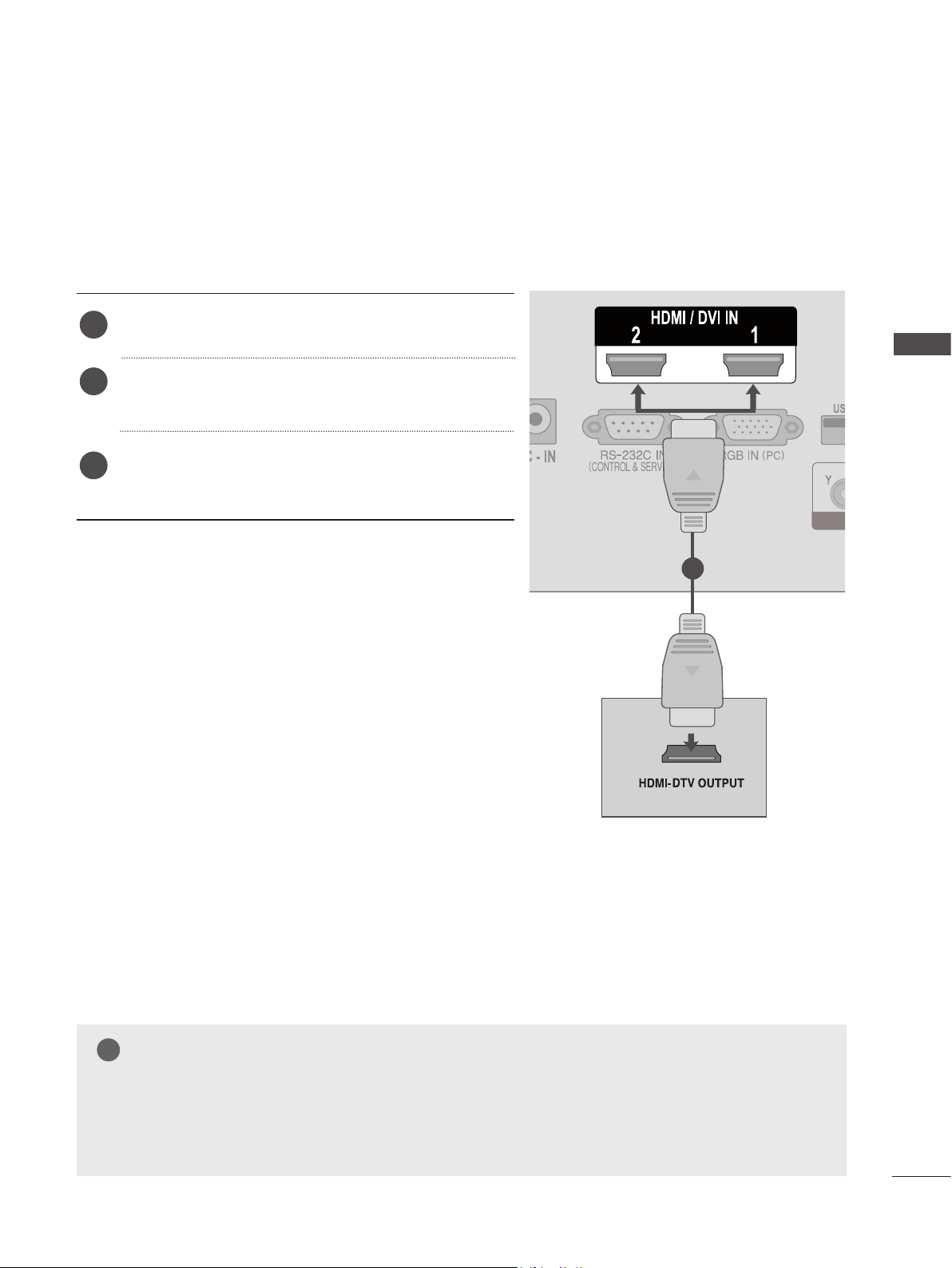
Connecting a set-top box with a HDMI cable
Connect the digital set-top box to HDMI/DVI IN 1 or
1
HDMI/DVI IN 2 jack on the SET
Turn on the digital set-top box.
2
(Refer to the owner’s manual for the digital set-top box.)
Select HDMI 1 or HDMI 2 input source using the
3
INPUT button on the remote control.
EXTERNAL EQUIPMENT SETUP
1
NOTE
!
►Check that your HDMI cable is High Speed HDMI Cable. If the HDMI cables are not High Speed
HDMI Cable, flickering or no screen display can result. Please use the High Speed HDMI Cable.
21
EXTERNAL EQUIPMENT SETUP
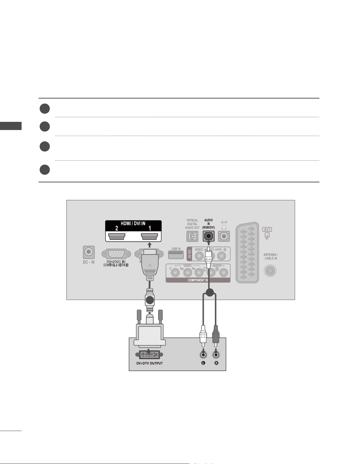
Connecting with an HDMI to DVI cable
Connect the digital set-top box to HDMI/DVI IN 1 or HDMI/DVI IN 2 jack on the SET.
1
Connect the audio output of the digital set-top box to the AUDIO IN (RGB/DVI) jack on the SET.
EXTERNAL EQUIPMENT SETUP
2
Turn on the digital set-top box.
3
(Refer to the owner’s manual for the digital set-top box.)
Select HDMI 1 or HDMI 2 input source using the INPUT button on the remote control.
4
22
2
1
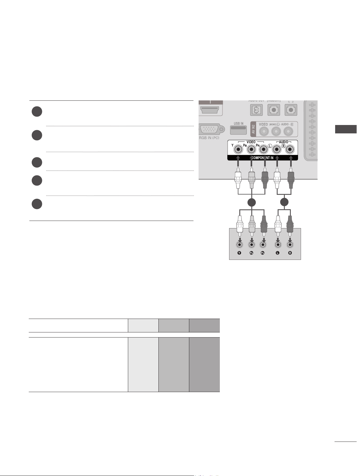
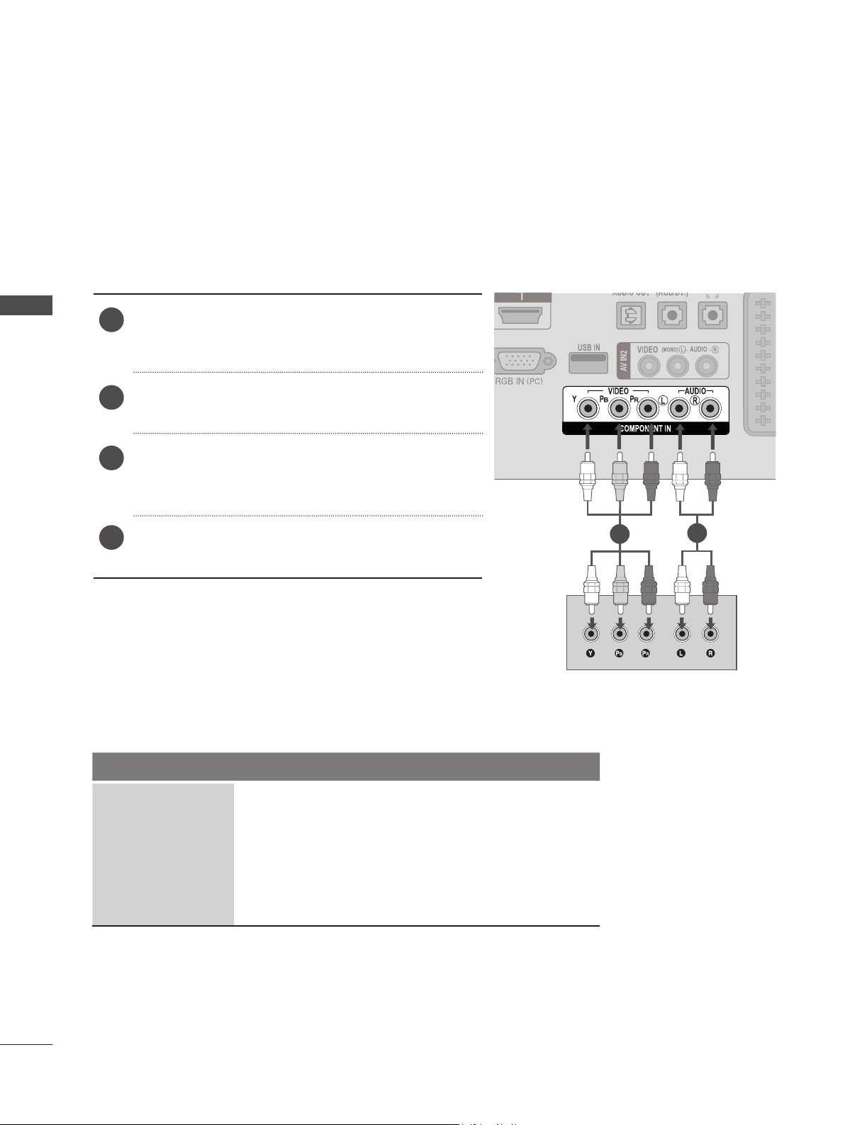
DVD SETUP
Connecting with a component cable
Connect the video outputs (Y, PB, PR) of the DVD
1
to the COMPONENT IN VIDEO jacks on the SET.
Connect the audio outputs of the DVD to the
2
COMPONENT IN AUDIO jacks on the SET.
Turn on the DVD player, insert a DVD.
3
Select Component input source using the INPUT
4
button on the remote control.
EXTERNAL EQUIPMENT SETUP
Refer to the DVD player's manual for operating
5
instructions.
Component Input ports
To achieve better picture quality, connect a DVD player to the component input ports as shown below.
Component ports on the SET Y P
Y P
Video output ports
on DVD player
Y P-Y R-Y
Y Cb Cr
B
B
P
R
P
R
1
2
Y Pb Pr
23
EXTERNAL EQUIPMENT SETUP
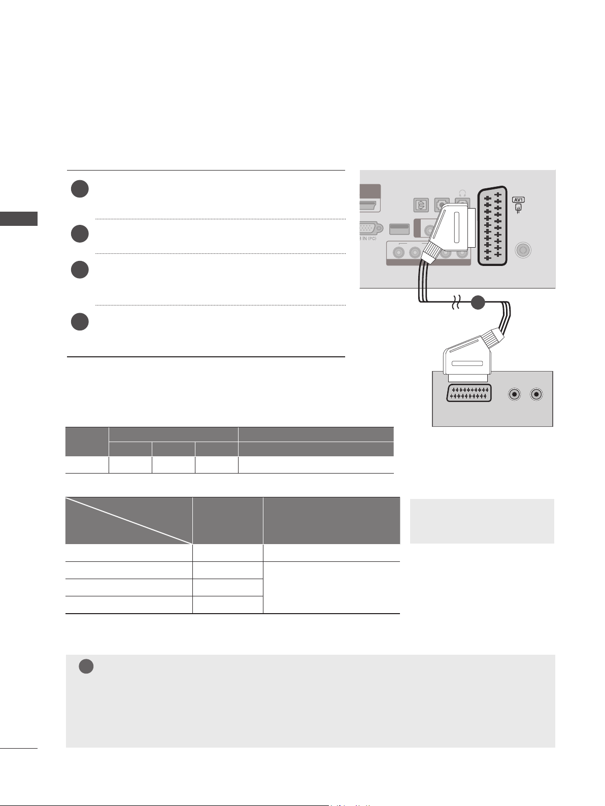
Connecting with a Euro Scart cable
Connect the Euro scart socket of the DVD to the AV1
1
Euro scart socket on the SET.
OPTICAL
AUDIO
IN
(RGB/DVI)
H / P
DIGITAL
1
AUDIO OUT
EXTERNAL EQUIPMENT SETUP
2
Turn on the DVD player, insert a DVD.
Select AV1 input source using the INPUT button on
3
the remote control.
Refer to the DVD player's manual for operating
4
instructions.
Scart
Video Audio RGB Video, Audio
AV1 O O O Analogue TV, Digital TV
Current input mode
Digital TV Digital TV O
Input Output
Output Type
AV1
(TV Out)
AV1
(When DTV scheduled recoring is in
progress using recording equipment)
USB IN
YP
(MONO) L -
AUDIO
- R
AUDIO
LR
VIDEO
BPR
VIDEO
AV IN2
1
AUDIO/
VIDEO
► TV Out : Outputs Analogue
TV or Digital TV signals.
ANTENNA /
CABLE IN
(R) AUDIO (L )
24
Analogue TV, AV Analogue TV
Component / RGB Analogue TV
HDMI X
NOTE
!
(The input mode is converted
O
to DTV)
►Signal type RGB, i.e. the signals red, green and blue can only be selected for the Euro scart and the
AV 1 can be received. These signals are transmitted, for example, by a paid TV decoder, game
machine or photo CD unit, etc.
►Please use shielded scart cable.
Connecting the HDMI cable
Connect the HDMI output of the DVD to the HDMI/DVI
1
IN 1 or HDMI/DVI IN 2 jack on the SET
Select HDMI 1 or HDMI 2 input source
2
using the INPUT button on the remote control.
Refer to the DVD player's manual for operating
3
instructions.
EXTERNAL EQUIPMENT SETUP
1
NOTE
!
►Check that your HDMI cable is High Speed HDMI Cable. If the HDMI cables are not High Speed
HDMI Cable, flickering or no screen display can result. Please use the High Speed HDMI Cable.
25
EXTERNAL EQUIPMENT SETUP
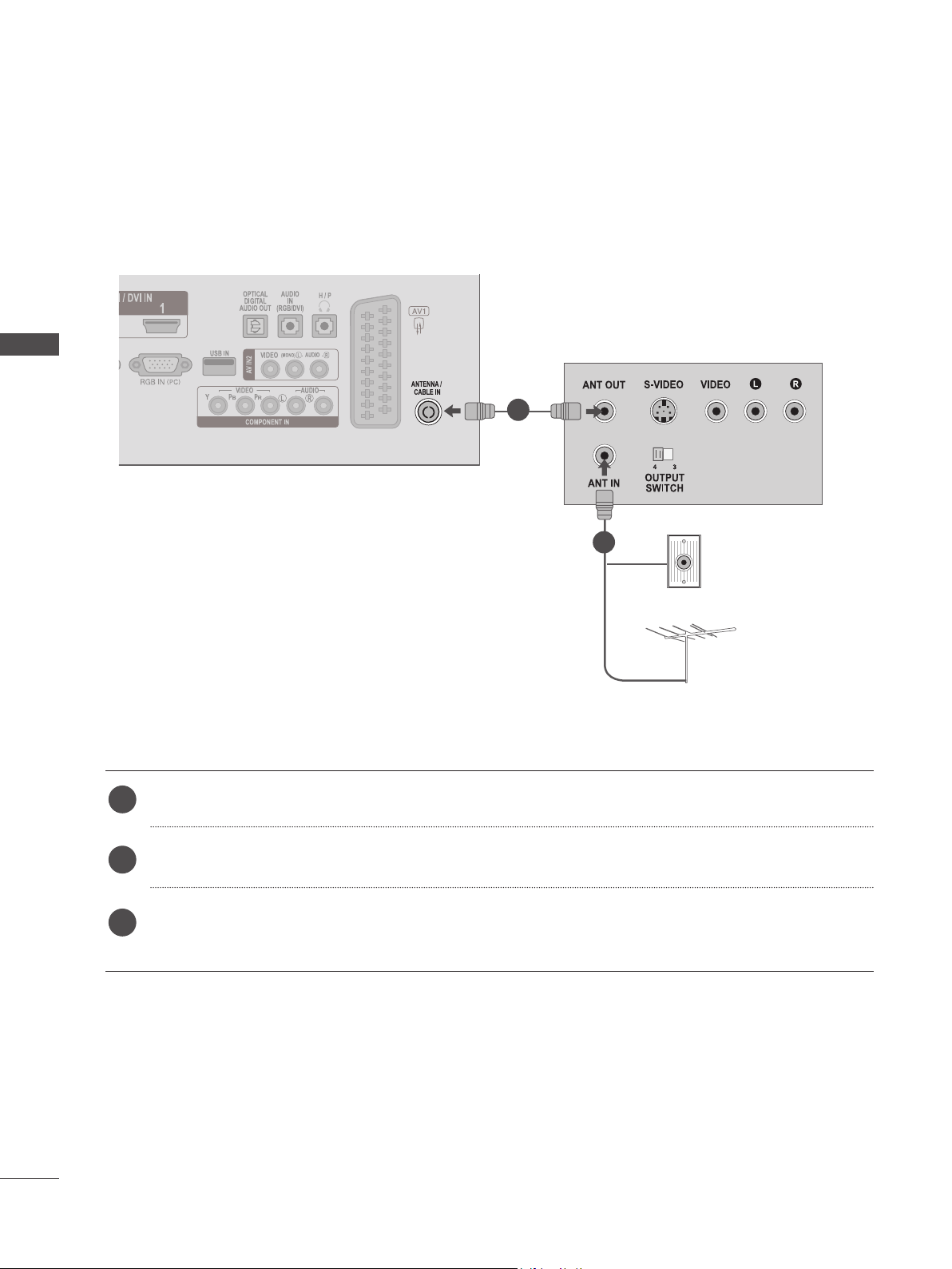
VCR SETUP
■ To avoid picture noise (interference), allow adequate distance between the VCR and SET.
Connecting with a RF cable
EXTERNAL EQUIPMENT SETUP
1
2
Connect the ANT OUT socket of the VCR to the ANTENNA / CABLE IN socket on the SET.
1
Connect the antenna cable to the ANT IN socket of the VCR.
2
Press the PLAY button on the VCR and match the appropriate channel between the SET and VCR
3
for viewing.
Wall Jack
Antenna
26
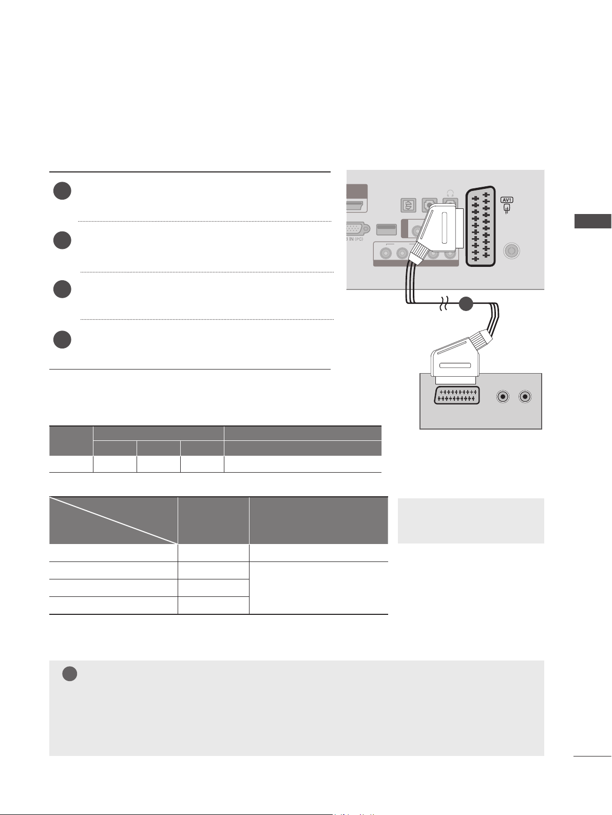
Connecting with a Euro Scart cable
Connect the Euro scart socket of the VCR to the AV1
1
Euro scart socket on the SET.
Insert a video tape into the VCR and press PLAY on
2
the VCR. (Refer to the VCR owner’s manual.)
Select AV1 input source using the INPUT button on
3
the remote control.
Refer to the VCR player's manual for operating
4
instructions.
OPTICAL
AUDIO
IN
(RGB/DVI)
(MONO) L -
LR
AUDIO
AUDIO
H / P
- R
ANTENNA /
CABLE IN
EXTERNAL EQUIPMENT SETUP
DIGITAL
USB IN
YP
AUDIO OUT
AV IN2
VIDEO
BPR
VIDEO
1
1
AUDIO/
VIDEO
Scart
Video Audio RGB Video, Audio
Input Output
AV1 O O O Analogue TV, Digital TV
Output Type
Current input mode
AV1
(TV Out)
(When DTV scheduled recoring is in
progress using recording equipment)
AV1
► TV Out : Outputs Analogue TV
or Digital TV signals.
Digital TV Digital TV O
Analogue TV, AV Analogue TV
Component / RGB Analogue TV
HDMI X
NOTE
!
(The input mode is converted
O
to DTV)
►Signal type RGB, i.e. the signals red, green and blue can only be selected for the Euro scart and the
AV 1 can be received. These signals are transmitted, for example, by a paid TV decoder, game
machine or photo CD unit, etc.
►Please use shielded scart cable.
(R) AUDIO (L )
27
EXTERNAL EQUIPMENT SETUP
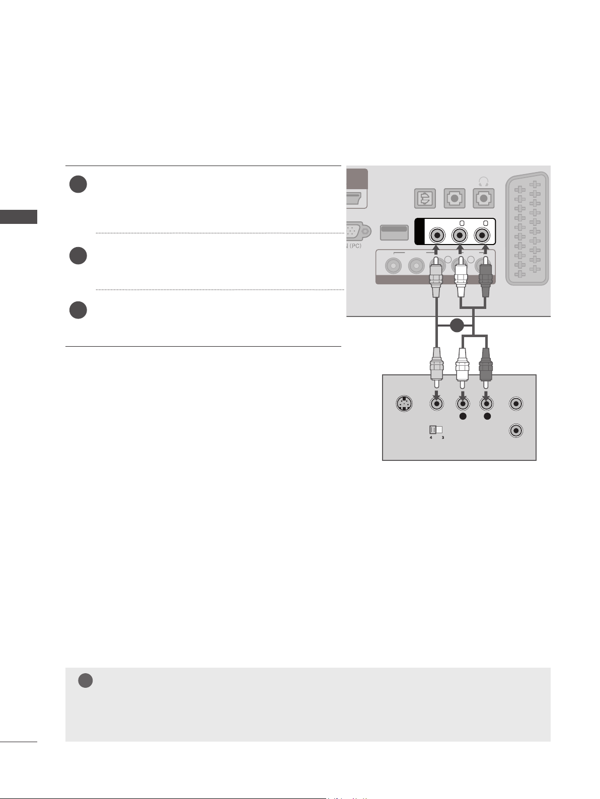
Connecting with a RCA cable
EXTERNAL EQUIPMENT SETUP
Connect the AUDIO/VIDEO jacks between SET and
1
VCR. Match the jack colours (Video = yellow, Audio
Left = white, and Audio Right = red)
Insert a video tape into the VCR and press PLAY on
2
the VCR. (Refer to the VCR owner’s manual.)
Select AV2 input source using the INPUT button on
3
the remote control.
USB IN
YP
S-VIDEO
OPTICAL
DIGITAL
AUDIO OUT
VIDEO
AV IN2
VIDEO
BPR
COMPONENT IN
VIDEO
OUTPUT
SWITCH
AUDIO
IN
(RGB/DVI)
(MONO) L -
AUDIO
LR
1
L
AUDIO
H / P
- R
R
ANT IN
ANT OUT
28
NOTE
!
►If you have a mono VCR, connect the audio cable from the VCR to the AUDIO L / MONO jack of
the SET.
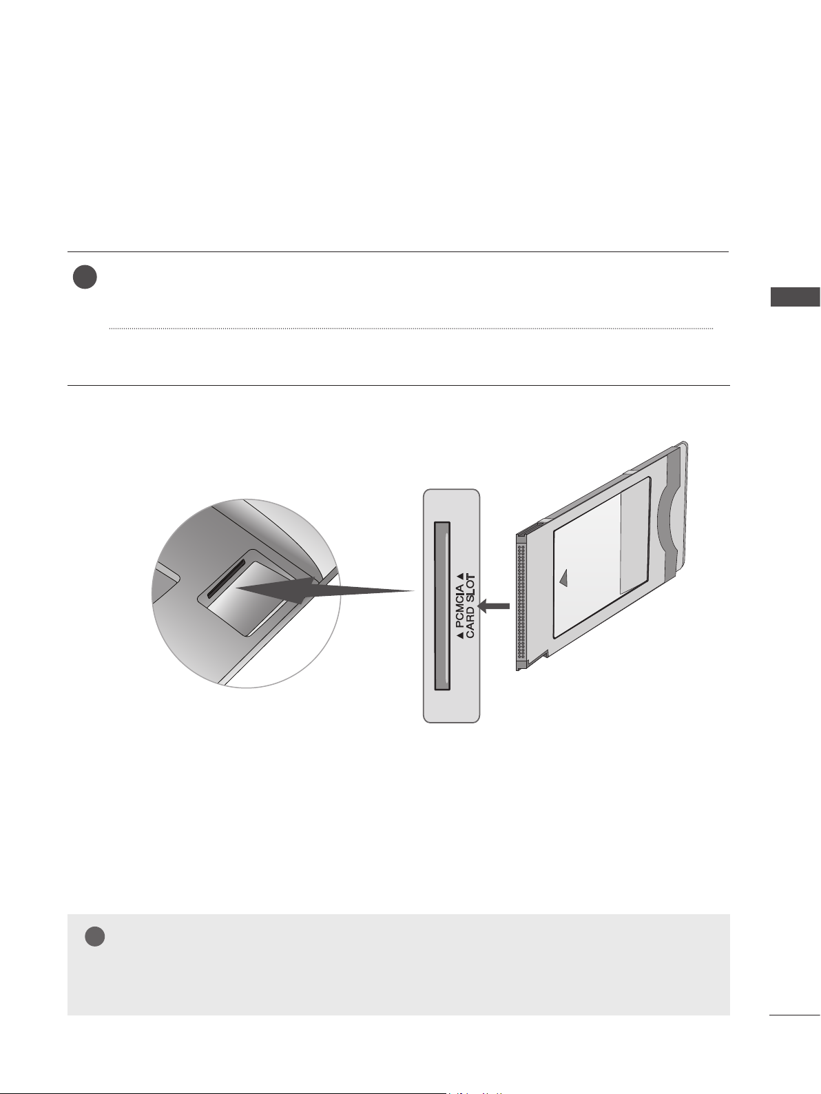
INSERTION OF CI MODULE
- To view the encrypted (pay) services in digital TV mode.
- This feature is not avai lable in al l countries.
Insert the CI Module to PCMCIA (Personal Computer Memory Card International Association)
1
CARD SLOT of SET as shown.
For further information, see p.61
EXTERNAL EQUIPMENT SETUP
NOTE
!
►Check if the CI module is inserted into the PCMCIA card slot in the right direction. If the module is
not inserted properly, this can cause damage to the TV and the PCMCIA card slot.
29
EXTERNAL EQUIPMENT SETUP
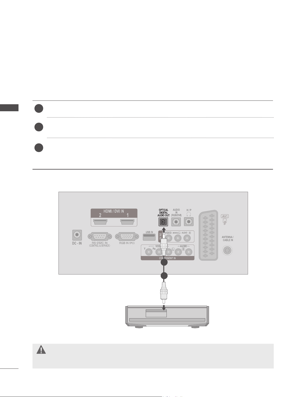
DIGITAL AUDIO OUT SETUP
Sending the TV’s audio signal to external audio equipment via the Digital Audio Output (Optical) port.
If you want to enjoy digital broadcasting through 5.1-channel speakers, connect the OPTICAL DIGITAL AUDIO OUT
terminal on the back of TV to a Home Theater (or amp).
Connect one end of an optical cable to the TV Digital Audio (Optical) Output port.
EXTERNAL EQUIPMENT SETUP
1
Connect the other end of the optical cable to the digital audio (Optical) input on the audio equipment.
2
Set the “TV Speaker option - Off ” in the AUDIO menu. (► P. 92)
3
Refer to the external audio equipment instruction manual for operation.
30
1
2
CAUTION
►Do not look into the optical output port. Looking at the laser beam may damage your vision.
 Loading...