

Page 1
LCD MONITOR TV
SERVICE MANUAL
CAUTION
BEFORE SERVICING THE CHASSIS,
READ THE SAFETY PRECAUTIONS IN THIS MANUAL.
CHASSIS : LD93A
MODEL : M2762D
M2762D-P(W)ZL
North/Latin America http://aic.lgservice.com
Europe/Africa http://eic.lgservice.com
Asia/Oceania http://biz.lgservice.com
Internal Use Only
P/NO : MFL62477305(0908-REV00) Printed in Korea
Page 2

Copyright ©2009 LG Electronics. Inc. All right reserved.
Only for training and service purposes
LGE Internal Use Only
- 2 -
CONTENTS
CONTENTS .............................................................................................. 2
PRECAUTIONS .........................................................................................3
SPECIFICATION ........................................................................................6
ADJUSTMENT INSTRUCTION ...............................................................13
TROUBLE SHOOTING ............................................................................17
BLOCK DIAGRAM...................................................................................25
EXPLODED VIEW .................................................................................. 26
SVC. SHEET ...............................................................................................
Page 3
Copyright ©2009 LG Electronics. Inc. All right reserved.
Only for training and service purposes
LGE Internal Use Only
- 3 -
SAFETY PRECAUTIONS
Many electrical and mechanical parts in this chassis have special safety-related characteristics. These parts are identified by in the
Schematic Diagram and Exploded View.
It is essential that these special safety parts should be replaced with the same components as recommended in this manual to prevent
Shock, Fire, or other Hazards.
Do not modify the original design without permission of manufacturer.
General Guidance
An isolation Transformer should always be used during the
servicing of a receiver whose chassis is not isolated from the AC
power line. Use a transformer of adequate power rating as this
protects the technician from accidents resulting in personal injury
from electrical shocks.
It will also protect the receiver and it's components from being
damaged by accidental shorts of the circuitry that may be
inadvertently introduced during the service operation.
If any fuse (or Fusible Resistor) in this TV receiver is blown,
replace it with the specified.
When replacing a high wattage resistor (Oxide Metal Film Resistor,
over 1W), keep the resistor 10mm away from PCB.
Keep wires away from high voltage or high temperature parts.
Before returning the receiver to the customer,
always perform an AC leakage current check on the exposed
metallic parts of the cabinet, such as antennas, terminals, etc., to
be sure the set is safe to operate without damage of electrical
shock.
Leakage Current Cold Check(Antenna Cold Check)
With the instrument AC plug removed from AC source, connect an
electrical jumper across the two AC plug prongs. Place the AC
switch in the on position, connect one lead of ohm-meter to the AC
plug prongs tied together and touch other ohm-meter lead in turn to
each exposed metallic parts such as antenna terminals, phone
jacks, etc.
If the exposed metallic part has a return path to the chassis, the
measured resistance should be between 1MΩ and 5.2MΩ.
When the exposed metal has no return path to the chassis the
reading must be infinite.
An other abnormality exists that must be corrected before the
receiver is returned to the customer.
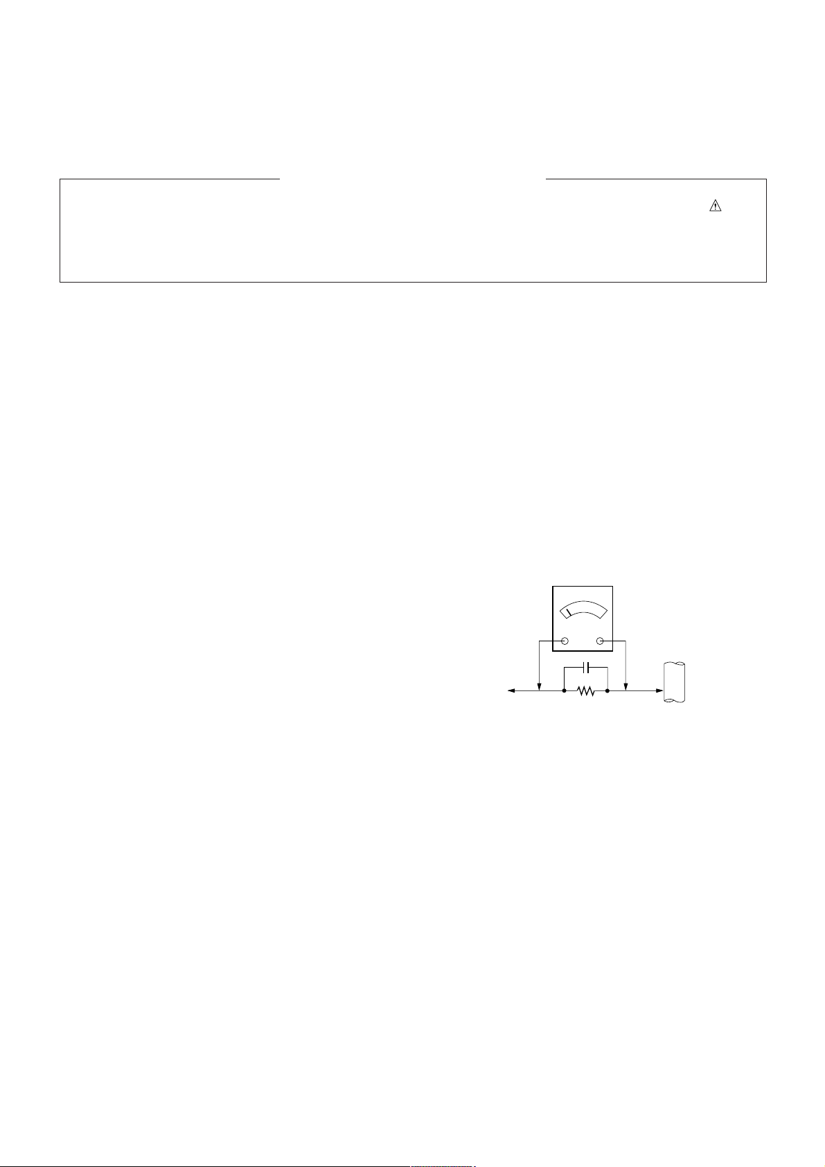
Leakage Current Hot Check (See below Figure)
Plug the AC cord directly into the AC outlet.
Do not use a line Isolation Transformer during this check.
Connect 1.5K/10watt resistor in parallel with a 0.15uF capacitor
between a known good earth ground (Water Pipe, Conduit, etc.)
and the exposed metallic parts.
Measure the AC voltage across the resistor using AC voltmeter
with 1000 ohms/volt or more sensitivity.
Reverse plug the AC cord into the AC outlet and repeat AC voltage
measurements for each exposed metallic part. Any voltage
measured must not exceed 0.75 volt RMS which is corresponds to
0.5mA.
In case any measurement is out of the limits specified, there is
possibility of shock hazard and the set must be checked and
repaired before it is returned to the customer.
Leakage Current Hot Check circuit
1.5 Kohm/10W
To Instrument's
exposed
METALLIC PARTS
Good Earth Ground
such as WATER PIPE,
CONDUIT etc.
AC Volt-meter
When 25A is impressed between Earth and 2nd Ground
for 1 second, Resistance must be less than 0.1
*Base on Adjustment standard
IMPORTANT SAFETY NOTICE
0.15uF
Ω
Page 4

Copyright ©2009 LG Electronics. Inc. All right reserved.
Only for training and service purposes
LGE Internal Use Only
- 4 -
CAUTION: Before servicing receivers covered by this service
manual and its supplements and addenda, read and follow the
SAFETY PRECAUTIONS on page 3 of this publication.
NOTE: If unforeseen circumstances create conflict between the
following servicing precautions and any of the safety precautions on
page 3 of this publication, always follow the safety precautions.
Remember: Safety First.
General Servicing Precautions
1. Always unplug the receiver AC power cord from the AC power
source before;
a. Removing or reinstalling any component, circuit board
module or any other receiver assembly.
b. Disconnecting or reconnecting any receiver electrical plug or
other electrical connection.
c. Connecting a test substitute in parallel with an electrolytic
capacitor in the receiver.
CAUTION: A wrong part substitution or incorrect polarity
installation of electrolytic capacitors may result in an
explosion hazard.
2. Test high voltage only by measuring it with an appropriate high
voltage meter or other voltage measuring device (DVM,
FETVOM, etc) equipped with a suitable high voltage probe.
Do not test high voltage by "drawing an arc".
3. Do not spray chemicals on or near this receiver or any of its
assemblies.
4. Unless specified otherwise in this service manual, clean
electrical contacts only by applying the following mixture to the
contacts with a pipe cleaner, cotton-tipped stick or comparable
non-abrasive applicator; 10% (by volume) Acetone and 90% (by
volume) isopropyl alcohol (90%-99% strength)
CAUTION: This is a flammable mixture.
Unless specified otherwise in this service manual, lubrication of
contacts in not required.
5. Do not defeat any plug/socket B+ voltage interlocks with which
receivers covered by this service manual might be equipped.
6. Do not apply AC power to this instrument and/or any of its
electrical assemblies unless all solid-state device heat sinks are
correctly installed.
7. Always connect the test receiver ground lead to the receiver
chassis ground before connecting the test receiver positive
lead.
Always remove the test receiver ground lead last.
8. Use with this receiver only the test fixtures specified in this
service manual.
CAUTION: Do not connect the test fixture ground strap to any
heat sink in this receiver.
Electrostatically Sensitive (ES) Devices
Some semiconductor (solid-state) devices can be damaged easily
by static electricity. Such components commonly are called
Electrostatically Sensitive (ES) Devices. Examples of typical ES
devices are integrated circuits and some field-effect transistors and
semiconductor "chip" components. The following techniques
should be used to help reduce the incidence of component
damage caused by static by static electricity.
1. Immediately before handling any semiconductor component or
semiconductor-equipped assembly, drain off any electrostatic
charge on your body by touching a known earth ground.
Alternatively, obtain and wear a commercially available
discharging wrist strap device, which should be removed to
prevent potential shock reasons prior to applying power to the
unit under test.
2. After removing an electrical assembly equipped with ES
devices, place the assembly on a conductive surface such as
aluminum foil, to prevent electrostatic charge buildup or
exposure of the assembly.
3. Use only a grounded-tip soldering iron to solder or unsolder ES
devices.
4. Use only an anti-static type solder removal device. Some solder
removal devices not classified as "anti-static" can generate
electrical charges sufficient to damage ES devices.
5. Do not use freon-propelled chemicals. These can generate
electrical charges sufficient to damage ES devices.
6. Do not remove a replacement ES device from its protective
package until immediately before you are ready to install it.
(Most replacement ES devices are packaged with leads
electrically shorted together by conductive foam, aluminum foil
or comparable conductive material).
7. Immediately before removing the protective material from the
leads of a replacement ES device, touch the protective material
to the chassis or circuit assembly into which the device will be
installed.
CAUTION: Be sure no power is applied to the chassis or circuit,
and observe all other safety precautions.
8. Minimize bodily motions when handling unpackaged
replacement ES devices. (Otherwise harmless motion such as
the brushing together of your clothes fabric or the lifting of your
foot from a carpeted floor can generate static electricity
sufficient to damage an ES device.)
General Soldering Guidelines
1. Use a grounded-tip, low-wattage soldering iron and appropriate
tip size and shape that will maintain tip temperature within the
range or 500ºF to 600ºF.
2. Use an appropriate gauge of RMA resin-core solder composed
of 60 parts tin/40 parts lead.
3. Keep the soldering iron tip clean and well tinned.
4. Thoroughly clean the surfaces to be soldered. Use a mall wirebristle (0.5 inch, or 1.25cm) brush with a metal handle.
Do not use freon-propelled spray-on cleaners.
5. Use the following unsoldering technique
a. Allow the soldering iron tip to reach normal temperature.
(500ºF to 600ºF)
b. Heat the component lead until the solder melts.
c. Quickly draw the melted solder with an anti-static, suction-
type solder removal device or with solder braid.
CAUTION: Work quickly to avoid overheating the circuit
board printed foil.
6. Use the following soldering technique.
a. Allow the soldering iron tip to reach a normal temperature
(500ºF to 600ºF)
b. First, hold the soldering iron tip and solder the strand against
the component lead until the solder melts.
c. Quickly move the soldering iron tip to the junction of the
component lead and the printed circuit foil, and hold it there
only until the solder flows onto and around both the
component lead and the foil.
CAUTION: Work quickly to avoid overheating the circuit
board printed foil.
d. Closely inspect the solder area and remove any excess or
splashed solder with a small wire-bristle brush.
SERVICING PRECAUTIONS
Page 5

Copyright ©2009 LG Electronics. Inc. All right reserved.
Only for training and service purposes
LGE Internal Use Only
- 5 -
IC Remove/Replacement
Some chassis circuit boards have slotted holes (oblong) through
which the IC leads are inserted and then bent flat against the
circuit foil. When holes are the slotted type, the following technique
should be used to remove and replace the IC. When working with
boards using the familiar round hole, use the standard technique
as outlined in paragraphs 5 and 6 above.
Removal
1. Desolder and straighten each IC lead in one operation by gently
prying up on the lead with the soldering iron tip as the solder
melts.
2. Draw away the melted solder with an anti-static suction-type
solder removal device (or with solder braid) before removing the
IC.
Replacement
1. Carefully insert the replacement IC in the circuit board.
2. Carefully bend each IC lead against the circuit foil pad and
solder it.
3. Clean the soldered areas with a small wire-bristle brush.
(It is not necessary to reapply acrylic coating to the areas).
"Small-Signal" Discrete Transistor
Removal/Replacement
1. Remove the defective transistor by clipping its leads as close as
possible to the component body.
2. Bend into a "U" shape the end of each of three leads remaining
on the circuit board.
3. Bend into a "U" shape the replacement transistor leads.
4. Connect the replacement transistor leads to the corresponding
leads extending from the circuit board and crimp the "U" with
long nose pliers to insure metal to metal contact then solder
each connection.
Power Output, Transistor Device
Removal/Replacement
1. Heat and remove all solder from around the transistor leads.
2. Remove the heat sink mounting screw (if so equipped).
3. Carefully remove the transistor from the heat sink of the circuit
board.
4. Insert new transistor in the circuit board.
5. Solder each transistor lead, and clip off excess lead.
6. Replace heat sink.
Diode Removal/Replacement
1. Remove defective diode by clipping its leads as close as
possible to diode body.
2. Bend the two remaining leads perpendicular y to the circuit
board.
3. Observing diode polarity, wrap each lead of the new diode
around the corresponding lead on the circuit board.
4. Securely crimp each connection and solder it.
5. Inspect (on the circuit board copper side) the solder joints of
the two "original" leads. If they are not shiny, reheat them and if
necessary, apply additional solder.
Fuse and Conventional Resistor
Removal/Replacement
1. Clip each fuse or resistor lead at top of the circuit board hollow
stake.
2. Securely crimp the leads of replacement component around
notch at stake top.
3. Solder the connections.
CAUTION: Maintain original spacing between the replaced
component and adjacent components and the circuit board to
prevent excessive component temperatures.
Circuit Board Foil Repair
Excessive heat applied to the copper foil of any printed circuit
board will weaken the adhesive that bonds the foil to the circuit
board causing the foil to separate from or "lift-off" the board. The
following guidelines and procedures should be followed whenever
this condition is encountered.
At IC Connections
To repair a defective copper pattern at IC connections use the
following procedure to install a jumper wire on the copper pattern
side of the circuit board. (Use this technique only on IC
connections).
1. Carefully remove the damaged copper pattern with a sharp
knife. (Remove only as much copper as absolutely necessary).
2. carefully scratch away the solder resist and acrylic coating (if
used) from the end of the remaining copper pattern.
3. Bend a small "U" in one end of a small gauge jumper wire and
carefully crimp it around the IC pin. Solder the IC connection.
4. Route the jumper wire along the path of the out-away copper
pattern and let it overlap the previously scraped end of the good
copper pattern. Solder the overlapped area and clip off any
excess jumper wire.
At Other Connections
Use the following technique to repair the defective copper pattern
at connections other than IC Pins. This technique involves the
installation of a jumper wire on the component side of the circuit
board.
1. Remove the defective copper pattern with a sharp knife.
Remove at least 1/4 inch of copper, to ensure that a hazardous
condition will not exist if the jumper wire opens.
2. Trace along the copper pattern from both sides of the pattern
break and locate the nearest component that is directly
connected to the affected copper pattern.
3. Connect insulated 20-gauge jumper wire from the lead of the
nearest component on one side of the pattern break to the lead
of the nearest component on the other side.
Carefully crimp and solder the connections.
CAUTION: Be sure the insulated jumper wire is dressed so the
it does not touch components or sharp edges.
Page 6
Copyright ©2009 LG Electronics. Inc. All right reserved.
Only for training and service purposes
LGE Internal Use Only
- 6 -
SPECIFICATION
NOTE : Specifications and others are subject to change without notice for improvement
.
1. Application Range.
1) This spec sheet is applied all of the LCD TV with LD93A
chassis.
2) Not included spec and each product spec in this spec sheet
apply correspondingly to the following each country standard
and requirement of Buyer
2. Specification
Each part is tested as below without special appointment
1) Temperature : 25±5°C(77±9°F) , CST: 40±5°C
2) Relative Humidity : 65±10%
3)
Power Voltage : Standard input voltage (100~240V@50/60Hz)
*Standard Voltage of each product is marked by models
4) Specification and performance of each parts are followed
each drawing and specification by part number in accordance
with BOM.
5) The receiver must be operated for about 20 minutes prior to
the adjustment.
3.Test method
1) Performance :
LGE TV test method followed
2) Demanded other specification
- Safety : CE,IEC specification
- EMC : CE,IEC specification
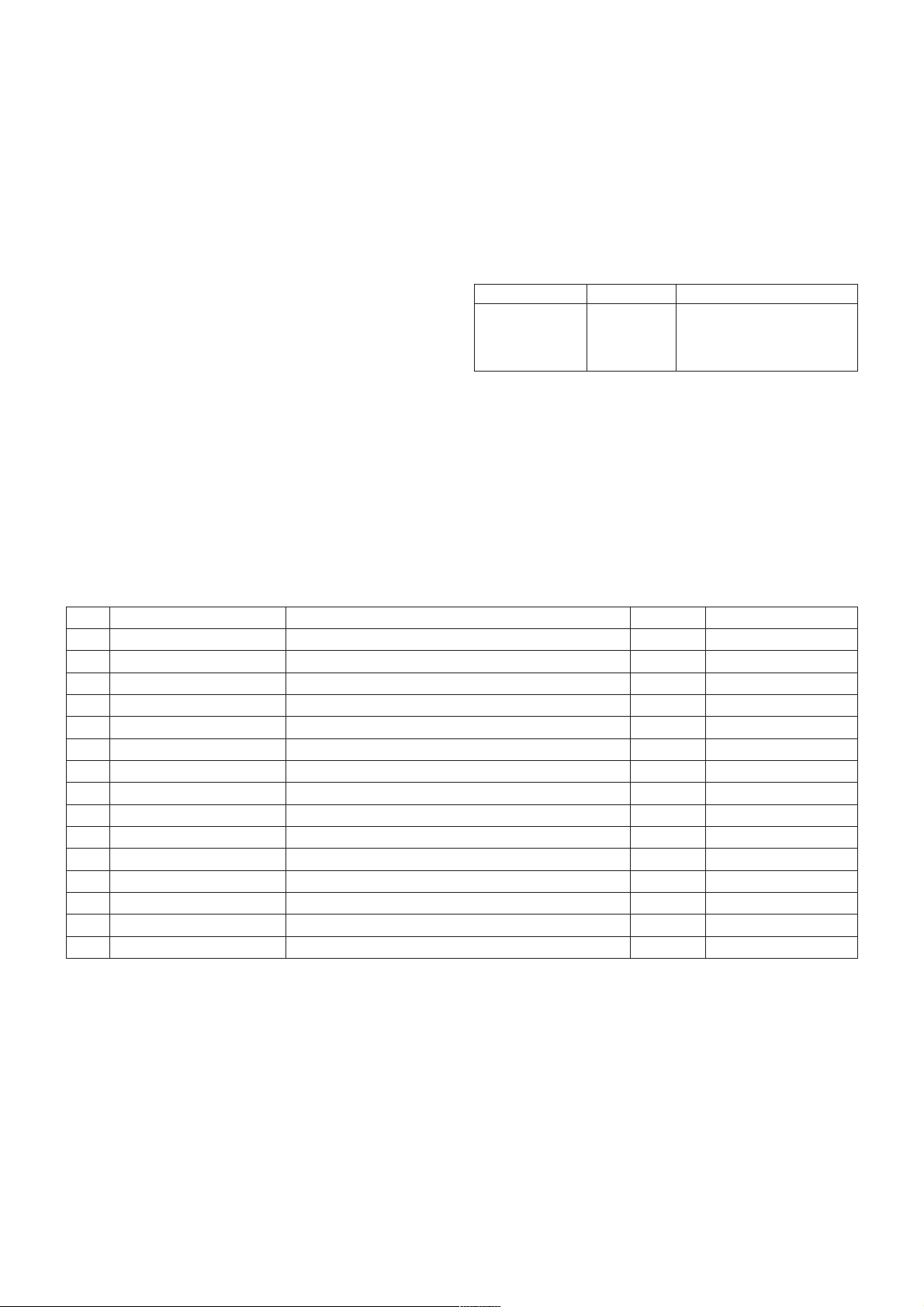
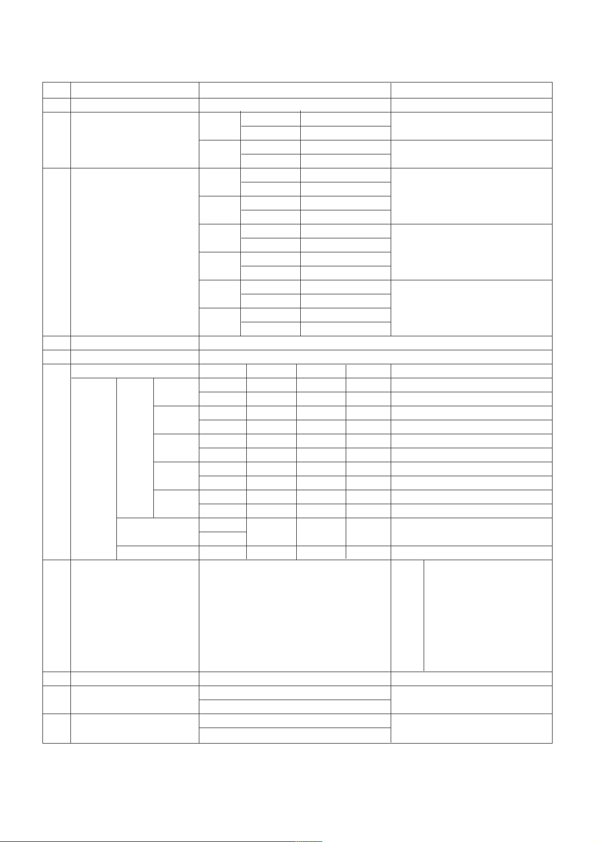
4. Electrical Specification
4.1 Module Specification
Model Market Appliance
Safety : IEC/ EN60065
Mx62D
EU
EMI :EN55013
(PAL Market)
EMS : EN55020
No Item Specification Unit Remark
1 Type TFT Color LCD Module
2 Diagonal Size 27 inches( 686.0mm) diagonal
3 Active Display area 597.89( H) 236.31( V) mm
4 Outline Dimension 630( H) x 368.2( V) x 21.6( D) mm Typ. (Without Inverter)
5 Aspect Ratio 16: 9
6 Pixel Number 1920 x RGB x 1080 pixel
7 Pixel Pitch 0.3114( H) x 0.3114 (V) mm
8 Color arrangement RGB vertical Stripe
9 Color Depth 16.7M color
10 Electrical Interface LVDS 2Port
11 Surface Treatment Hard coating( 3H) & Anti- glare( Haze 25)
12 Operating Mode Normally White
13 Backlight Unit 4 CCFL (4 lamps)
14 Response Time Rising Time : 1 + Falling Time : 4 ms Typ.
15 Color Gamut 72%
- M2762D- P(W)ZL : LGD / LM270WF1- TLD1 ( P/ N : EAJ60703601)
Page 7
- 7 -
Copyright ©2009 LG Electronics. Inc. All right reserved.
Only for training and service purposes
LGE Internal Use Only
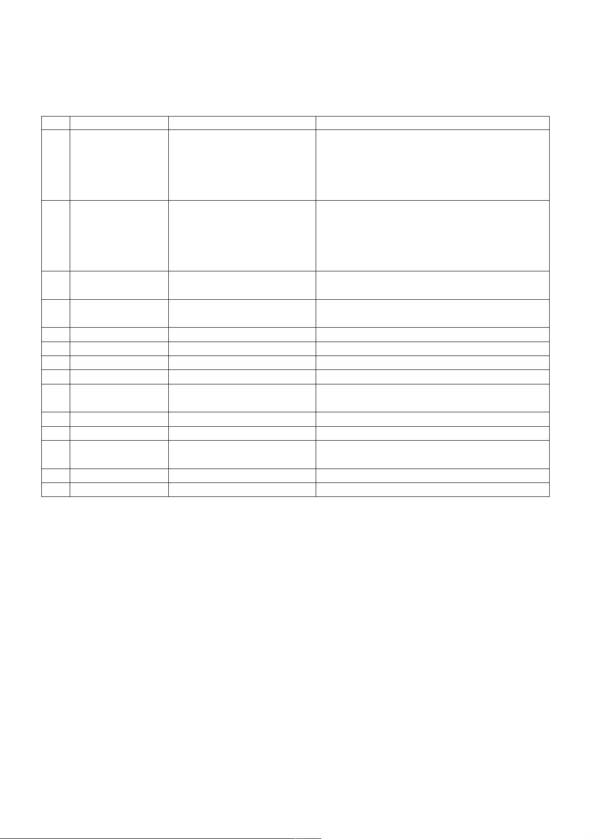
No Item Specification Remarks
DTV &Analog- UK,France,Germany,Spain,Sweden,Finland,
Italy,Netherland,Belgium,Czech,Luxemburg,Greece,
1 Market EU(PAL Market-26Countries) Denmark,Austria,Hungary,Switzerland,Croatia,Turkey
Analog Only -Poland,Portugal,Norway,Bulgaria,Serbia,
Slovenia,Russia,Romania
1) PAL-BG
2) PAL-DK
2 Broadcasting system 3) PAL-I/I’
4) SECAM L/L’
5) DVB-T
3 Receiving system
Analog : Upper Heterodyne
Digital : COFDM
4 Scart Jack (2EA) PAL,SECAM
Scart 1 Jack is Full scart and support RF-OUT(ATV)
Scart 2 jack is Half scart and support MNT/DTV-OUT.
5 Component Input (1EA) Y/Cb/CrY/Pb/Pr
6 CVBS Input (1EA) PAL,SECAM,NTSC 4 System(Rear):PAL50,SECAM,NTSC,PAL60
7 RGB Input RGB-PC Analog(D-SUB 15Pin)
8 DVI Input DVI-D Digital
9 HDMI Input (2EA)
HDMI1-DTV 1ea(Rear),1ea(Side)
HDMI2-DTV HDMI version 1.3 Support HDCP / Not support PC
10 Audio Input (3EA) RGB/DVI Audio, Component, CVBS L/R Input
11 SPDIF out (1EA) SPDIF out
12 Earphone out (1EA)
Antenna,AV1,AV2,AV3,Component,
RGB,DVI,HDMI1,HDMI2
13 USB (1EA) Picture,Music Software Update +Picture +Music
14 RS-232C (1EA) Commercial Mode
5. General specification
5.1 TV
Page 8
- 8 -
Copyright ©2009 LG Electronics. Inc. All right reserved.
Only for training and service purposes
LGE Internal Use Only
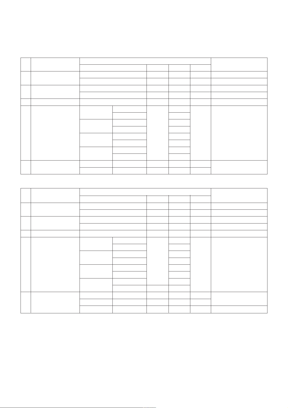
5.2 RGB
No Item Specification Remark
1 Supported Sync.Type Separate Sync.,Digital
Horizontal 30~83kHz
Analog
Vertical 56~75 Hz
2 Operating Frequency
Horizontal 30~83kHz
Digital
Vertical 56~75 Hz
Max. 1360 x 768 @60Hz
Analog
Recommend 1360 x 768 @60Hz
Max. 1360 x 768 @60Hz
M1962D
Digital
Recommend 1360 x 768 @60Hz
Max. 1600 x 900 @60Hz
3 Resolution
Analog
Recommend 1600 x 900 @60Hz
Max. 1600 x 900 @60Hz
M2062D
Digital
Recommend 1600 x 900 @60Hz
Max. 1920 x 1080 @60Hz
Analog
Recommend 1920 x 1080 @60Hz
M2262D/M2362D/M2762D
Max. 1920 x1080 @60Hz
Digital
Recommend 1920 x1080 @60Hz
4 Input Voltage Voltage :100 ~240 Vac,50 or 60Hz
5 Inrush Current Cold Start :50 A/ Hot :120 A
Operating Condition Sync (H/V) Video LED Wattage
On/On Active Blue 40 Max.
M1962D
On/On Active Blue 35 Typ.
On/On Active Blue 60 Max.
M2062D
On/On Active Blue 50 Typ.
6 Power On On/On Active Blue 60 Max.
S/W Mode
M2262D
On/On Active Blue 53 Typ.
On/On Active Blue 65 Max.
M2362D
On/On Active Blue 55 Typ.
On/On Active Blue 70 Max.
M2762D
On/On Active Blue 63 Typ.
Off/On
Sleep mode
On/Off
Off Amber 1W RGB / DVI
Off mode - Off Off 0.5W
19”LGD :50,000 Hours(min)
19”AUO :50,000 Hours(min)
20”LGD :50,000 Hours(min)
Lamp 20”CMO :40,000 Hours(min)
7 MTBF 50,000 HRS with 90%Confidence level Life 22”LGD :50,000 Hours(min)
22”AUO :40,000 Hours(min)
23”LGD :50,000 Hours(min)
27”LGD :50,000 Hours(min)
8 Using Altitude 5,000 m (for Reliability) 3,000m(for FOS)
9 Operating Environment
Temp :10°C ~35°C
Humidity :20 %~80 %
10 Storage Environment
Temp :-10°C ~60°C non condensing
Humidity :5 %~90 %non condensing
Page 9
- 9 -
Copyright ©2009 LG Electronics. Inc. All right reserved.
Only for training and service purposes
LGE Internal Use Only
6. Chroma & Brightness
6.1 M2362D – LGD Module
No. Item
Specification
Remark
Min typ Max
1. Viewing Angle[CR>10]
Right/Left 70/70 85/85 -
Up/Down 60/70 75/85 -
2. Luminance
Luminance (cd/m
2
) 250 300 -
Variation(%) 75 - -
3. Contrast Ratio CR 700 1000 - Full white/ Full black
White Wx 0.313
Wy 0.329
RED Rx Typ 0.644 Typ DVI or RGB
4. Color Coordinates Ry -0.03 0.336
+0.03
- Standard, 6500K
[CIE 1931] Green Gx 0.301 - Full White (100IRE)
Gy 0.611 - Backlight 100
Blue Bx 0.146
By 0.070
Rise Time Tr
R 1.3 2.6 Condition : DVI or RGB
5. Response Time
Decay Time Tr
D 3.7 7.4 Standard, Backlight100
6.3 Optical Test Condition
- Surrounding Brightness Level : dark
- Surrounding Temperature : 25±5°C
- warm-up Time :30 Min
- Contrast,Brightness : Outgoing condition
-.*Incase of Vivid Mode, high level saturation may be occurred. Check gray linearity at standard mode.
6.2 M2762D –LGD Module
No. Item
Specification
Remark
Min typ Max
1. Viewing Angle[CR>10]
Right/Left 70/70 85/85 -
Up/Down 60/70 75/85 -
2. Luminance
Luminance (cd/m2) 250 300 -
Variation(%) 75 - -
3. Contrast Ratio CR 700 1000 - Full White/ Full black
White Wx 0.313
Wy 0.329
RED Rx Typ 0.637 Typ DVI or RGB
4. Color Coordinates Ry -0.03 0.337
+0.03
- Standard, 6500K
[CIE 1931] Green Gx 0.298 - Full White (100IRE)
Gy 0.613 - Backlight 100
Blue Bx 0.147
By 0.057
Rise Time Tr
R 1 4 Condition : DVI or RGB
5. Response Time
Decay Time Tr
D 4 8 Standard, Backlight100
Gray to Gray T
GrD_AVR
26
Page 10
- 10 -
Copyright ©2009 LG Electronics. Inc. All right reserved.
Only for training and service purposes
LGE Internal Use Only
No Item Min Typ Max Remark
1. Cool
White Balance,X axis 0.268 0.283 0.298 DQA :±0.015
White Balance,Y axis 0.283 0.298 0.313 DQA :±0.015
2. Medium
White Balance,X axis 0.280 0.295 0.310 DQA :±0.015
White Balance,Y axis 0.290 0.305 0.320 DQA :±0.015 Measurement Condition
3. Warm
White Balance,X axis 0.298 0.313 0.328 DQA :±0.015 PSM :Outgoing condition
White Balance,Y axis 0.314 0.329 0.344 DQA :±0.015 Input signal :White pattern(85IRE)
4. 6500k
White Balance,X axis 0.298 0.313 0.328 DQA :±0.015 Pattern number :78 (MSPG series)
White Balance,Y axis 0.314 0.329 0.344 DQA :±0.015
5. 9300k
White Balance,X axis 0.268 0.283 0.298 DQA :±0.015
White Balance,Y axis 0.283 0.298 0.313 DQA :±0.015
7. Chroma (PSM : PC Mode-Standard, AV Mode-Vivid)
No Item
Luminance(cd/m
2
) C/R(min)
Remark
Typ Max RF,AV,COMPONENT,HDMI
1 M1962D 120 150 500 RF, AV, COMPONENT, HDMI
2 M2062D 170 200 500 Test Condition
3 M2262D 170 200 500 Mode :Outgoing condition
4 M2362D 170 200 500 Input signal : 100IRE White pattern
5 M2762D 170 200 500 (Pattern #4 : MSPG series)
- AV Mode
8.2 Special feature(DFC)
- DFC Working Condition : Full Black Pattern( All Black, No pattern( MSPG Pattern# 2)) signal in D- sub & DVI
No Item Min Typ Max Remark
M1962D/ M2062D/ M2262D/
PC Mode( D- sub, DVI), Mode : Outgoing condition
1
M2362D/ M2762D
40000: 1 50000: 1 -
Input signal : 100 IRE Full white pattern
8. SET Optical Feature
8.1 General feature
- PC Mode
No Item
Luminance(cd/m
2
) C/R
Remark
Min Typ Max Min Typ
1 M1962D 150 180 500 700 RGB &DVI
2 M2062D 200 230 500 700 DFC 50000:1(Typ)
3 M2262D 200 230 500 700 -Mode :Outgoing condition
4 M2362D 200 230 500 700 Input signal :100IRE White pattern
5 M2762D 200 230 500 700 (Pattern #4 :MSPG series)
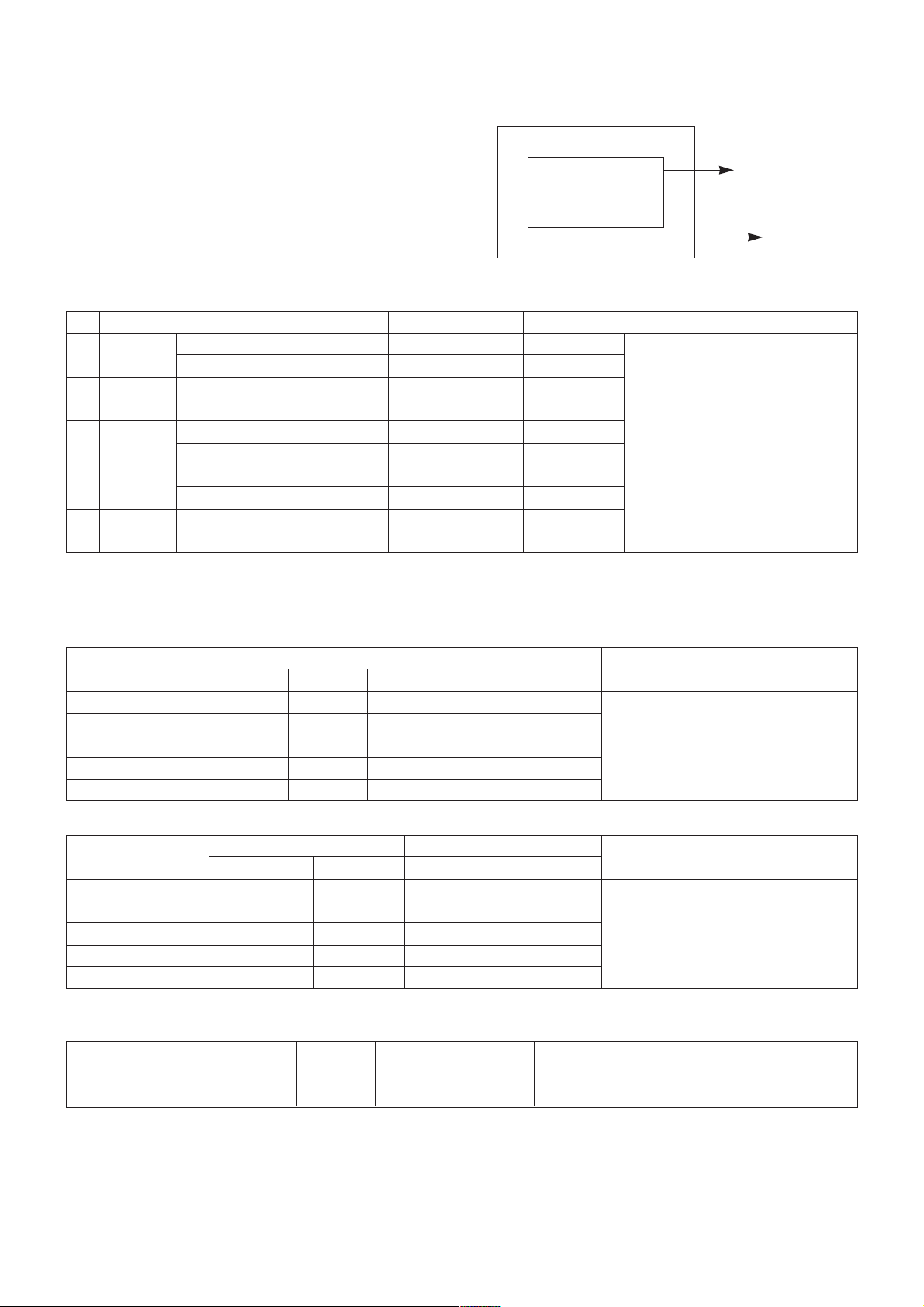
6.4 Active area
1. Active area of LCD PANEL is in bezel of cabinet.
2. Interval between active area and bezel
|A-B| ≤ 1.0 mm , |C-D| ≤ 1.0 mm
A: Interval between left of active area and bezel
B: Interval between right of active area and bezel
C: Interval between top of active area and bezel
D: Interval between bottom of active area and bezel
C
B
D
A
Active Area
Bezel
Page 11
- 11 -
Copyright ©2009 LG Electronics. Inc. All right reserved.
Only for training and service purposes
LGE Internal Use Only
No.
Specification
Remark
Resolution H-freq(kHz) V-freq(Hz) Pixel clock( MHz)
1. 720* 480 15.73 59.94 13.500 SDTV, DVD 480I( 525I)
2. 720* 480 15.75 60.00 13.514 SDTV, DVD 480I( 525I)
3. 720* 576 15.625 50.00 13.500 SDTV, DVD 576I( 625I) 50Hz
4. 720* 480 31.47 59.94 27.000 SDTV 480P
5. 720* 480 31.50 60.00 27.027 SDTV 480P
6. 720* 576 31.25 50.00 27.000 SDTV 576P 50Hz
7. 1280* 720 44.96 59.94 74.176 HDTV 720P
8. 1280* 720 45.00 60.00 74.250 HDTV 720P
9. 1280* 720 37.50 50.00 74.25 HDTV 720P 50Hz
10. 1920* 1080 33.72 59.94 74.176 HDTV 1080I
11. 1920* 1080 33.75 60.00 74.250 HDTV 1080I
12. 1920* 1080 28.125 50.00 74.250 HDTV 1080I 50Hz,
13. 1920* 1080 56.25 50 148.5 HDTV 1080P
14. 1920* 1080 67.432 59.94 148.350 HDTV 1080P
15. 1920* 1080 67.5 60.00 148.5 HDTV 1080P
9. Component Video Input (Y, PB , PR)
10. RGB/DVI INPUT (PC)
No. Resolution H-freq(kHz) V-freq(Hz) Pixel clock(MHz) Remark
1. 720*400 31.468 70.08 28.321
2. 640*480 31.469 59.94 25.175
3. 640*480 37.5 75 31.5
4. 800*600 37.879 60.317 40.0
5. 800*600 46.875 75.0 49.5
6. 1024*768 48.363 60.0 65.0
7. 1024*768 60.123 75.029 78.75
8. 1152*864 67.500 75.000 108.0
9. 1280*1024 63.981 60.02 108.0
10. 1280*1024 79.976 75.035 135.0
11. 1680*1050 64.674 59.883 119.0
12. 1680*1050 65.290 59.954 146.25
13. 1600*1200 75.0 60.0 162.0
14. 1920*1080 66.587 59.934 138.5
Page 12
- 12 -
Copyright ©2009 LG Electronics. Inc. All right reserved.
Only for training and service purposes
LGE Internal Use Only
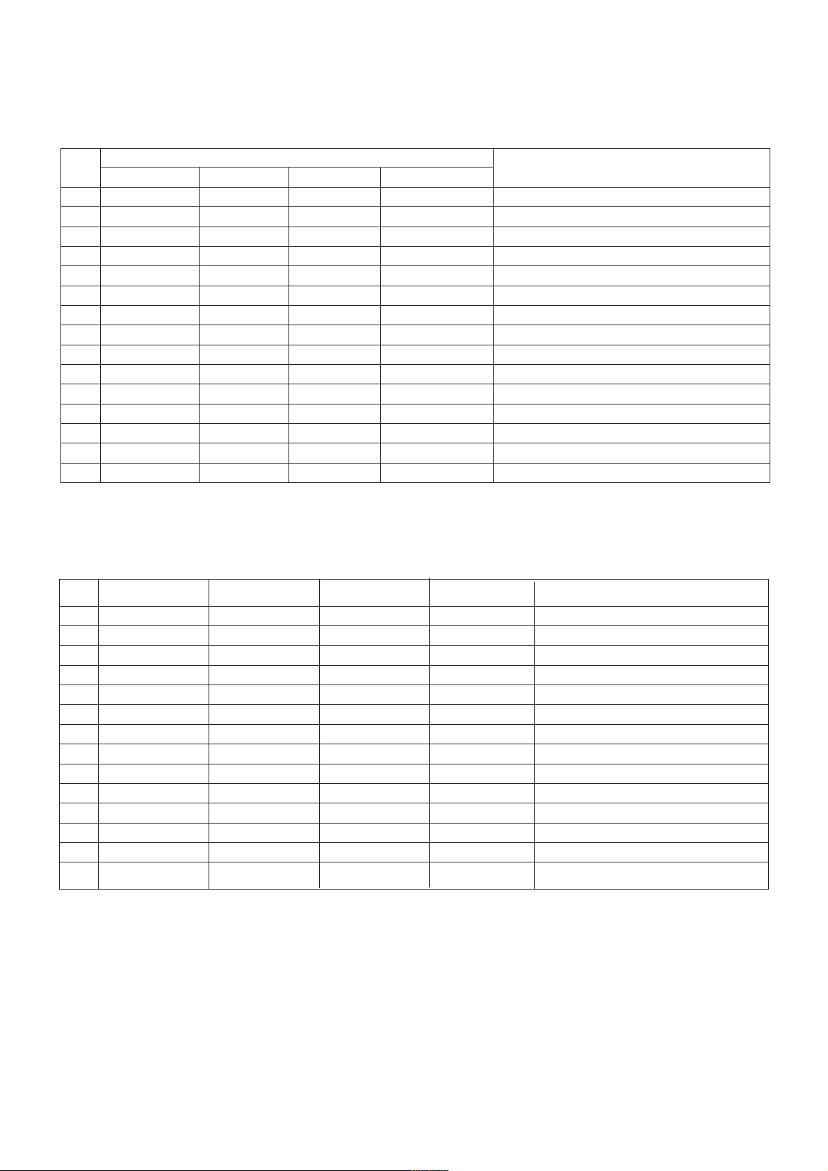
11. HDMI INPUT(DTV)
No. Resolution H-freq(kHz) V-freq(Hz) Pixel clock(MHz) Remark
1 720* 480 31.469 / 31.5 59.94 / 60 27.00/ 27.03 SDTV 480P
2 720* 576 31.25 50 27.864 SDTV 576P
3 1280* 720 37.500 50 74.25 HDTV 720P
4 1280* 720 44.96 / 45 59.94 / 60 74.17/ 74.25 HDTV 720P
5 1920* 1080 33.72 / 33.75 59.94 / 60 74.17/ 74.25 HDTV 1080I
6 1920* 1080 28.125 50.00 74.25 HDTV 1080I
7 1920* 1080 27 24 74.25 HDTV 1080P
8 1920* 1080 33.75 30.00 74.25 HDTV 1080P
9 1920* 1080 56.250 50 148.5 HDTV 1080P
10 1920* 1080 67.43 / 67.5 59.94 / 60 148.35/ 148.50 HDTV 1080P
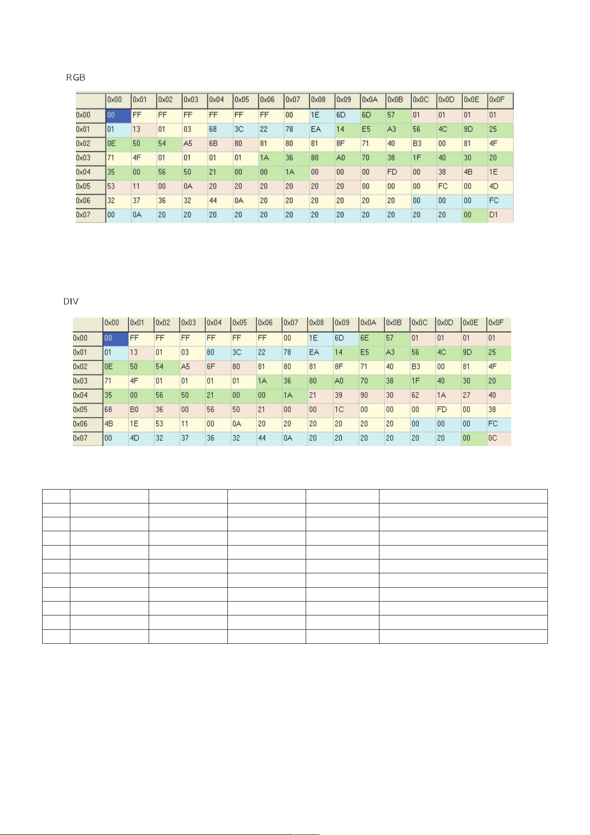
10.2 EDID Data (Product ID : 22382)
10.1 EDID Data (Product ID : 22381)
Page 13

Copyright ©2009 LG Electronics. Inc. All right reserved.
Only for training and service purposes
LGE Internal Use Only
- 13 -
ADJUSTMENT INSTRUCTION
1. Application
This document is applied to LD93A chassis 19/20/22/23/27”
LCD Monitor TV which is manufactured in TV (or Monitor)
Factory or is produced on the basis of this data.
2. Designation
2.1 The adjustment is according to the order which is
designated and which must be followed, according to the
plan which can be changed only on agreeing.
2.2. Power Adjustment: Free Voltage
2.3. Magnetic Field Condition: Nil.
2.4. Input signal Unit: Product Specification Standard
2.5. Reserve after operation: Above 5 Minutes (Heat Run)
Temperature : at 25°C ± 5°C
Relative humidity : 65 ±10%
Input voltage : 220V, 60Hz
2.6. Adjustment equipment: Color Analyzer (CA-210 or CA-
110), Pattern Generator (MSPG-925L or Equivalent),
DDC Adjustment Jig equipment, SVC remote controller
2.7. Don’t push The “IN STOP KEY” after completing the
function inspection.
3. Tool Option
4. Main PCB check process
• APC - After Manual-Insult, executing APC
4.1 Download
1. Execute ISP program "Mstar ISP Utility" and then click
"Config" tab.
2. Set as below, and then click "Auto Detect" and check "OK"
message.
If display "Error", Check connect computer, jig, and set.
3. Click "Connect" tab.
If display "Can’t ", Check connect computer, jig, and set.
4. Click "Read" tab, and then load download file(XXXX.bin)
by clicking "Read"
5. Click "Auto" tab and set as below
6. Click "Run".
7. After downloading, check "OK" message.
(1) (3)
Please Check the Speed :
To use speed between
from 200KHz to 400KHz
(4)
filexxx.bin
filexxx.bin
(7)
(5)
(8) ……….OK
(6)
Model Module Tool option
M1962D-P(W)ZL
LGD 4301
AUO 37069
M2062D-P(W)ZL
LGD 4557
CMO 20941
M2262D-P(W)ZL LGD/AUO 4813 / 37581
M2362D-P(W)ZL LGD 5069
M2762D-P(W)ZL LGD/CMO 5325 / 21709
Page 14

Copyright ©2009 LG Electronics. Inc. All right reserved.
Only for training and service purposes
LGE Internal Use Only
- 14 -
4.2 DOWNLOAD USB
1. Put the USB Stick to the USB socket
2. Automatically detecting update file in USB Stick
- If your downloaded program version in USB Stick is Low, it
didn’t work.
But your downloaded version is High, USB data is
automatically detecting
3. Show the message “Copying files from memory”
4. Updating is staring.
5. Updating Completed, The TV will restart automatically.
6. If your TV is turned on, check your updated version and Tool
option. (explain the Tool option, next stage)
* If downloading version is more high than your TV have, TV can
lost all channel data. In this case, you have to channel recover.
if all channel data is cleared, you didn’t have a DTV/ATV test on
production line.
* After downloading, have to adjust TOOL OPTION again.
1. Push "ADJ" key in service remote controller
2. Select "1.Tool Option" and Push “OK” button
3. Punch in the number. (Each model has their number.)
4. Completed selecting Tool option
4.3 ADC Process
4.3.1 ADC Calibration Internal
: ADC is executed automatically using internal pattern.
- If ADC is executed by ADC Calibration Internal, RGB and
Component is executed at the same time.
· Remove the all input jack from set.
· Press the ADJ KEY on R/C and enter EZ ADJUST.
· Press “Power only” key of service remocon.(Baud rate :
115200 bps).
· Select “3. ADC CALIBRATION Internal” by using / (CH
+/-) and press ENTER( ).
· Select “Start” and press navigation key( ).
· ADC Calibration Internal is executed automatically.
· Press EXIT key on R/C
4.3.2 ADC Calibration External
( If ADC calibration had done in internal process, It doesn’t need
to use this process.)
1) Auto RGB Gain/Offset Adjustment
· Convert to PC in Input-source
· Signal equipment displays
Output Voltage: 700 mVp-p
Impress Resolution XGA (1024 x 768 @ 60Hz)
Model : 60 in Pattern Generator
Pattern : 29 in Pattern Generator (MSPG-925 SERISE)
Adjustment pattern (PC )
· Press the ADJ KEY and then select “2.ADC CALIBRATION
External” by using
/
(CH +/-) and press ENTER( ).
!
EZ ADJUST
1. Tool Option : 1229
2. ADC CALIBRATION External : DTV
3. ADC CALIBRATION Internal
4. ADC ADJUST
5. W/B ADJUST
6. WHITE PATTERN : OFF
7. EDID D.L
Tool Option : 1229
Model Name : M2794DP-PZ
Inch : 27
Tool : Mx94DP
DSUB Port : RGB 0 (NEW)
Media Player : EMF-PM
HDMI Type : 3-HDMI
OK to Download
DOWNLOAD:
Page 15

- 15 -
Copyright ©2009 LG Electronics. Inc. All right reserved.
Only for training and service purposes
LGE Internal Use Only
1-1) Confirmation
· We confirm whether “0xAA (RGB)” address of EEPROM
“0xA2” is “0xAA” or not.
· If “0xAA (RGB)” address of EEPROM “0xA2” isn’t “0xAA”, we
adjust once more
· We can confirm the ADC values from “0xA4~0XA9 (RGB)”
addresses in a page “0xA2”
*Manual ADC process using Service Remocon. After enter
Service Mode by pushing “ADJ” key, execute “4.ADC Adjust” by
pushing “ ” key at “ADC CALIBRATION: RGB”.
2) Component Gain/Offset Adjustment
· Convert to Component in Input-source
· Signal equipment displays
Impress Resolution 1080i
MODEL: 223 in Pattern Generator(1080i Mode)
PATTERN: 65 in Pattern Generator(MSPG-925 SERISE)*
Adjustment pattern (COMPONENT )
· Press the ADJ KEY and then select “2.ADC CALIBRATION
External” by using
/
(CH +/-) and press ENTER( ).
2-1) Confirmation
· We confirm whether “0xB3 (480i)/0xBC (1080i)” address of
EEPROM “0xA2” is “0xAA” or not.
· If “0xB3 (480i)/0xBC(1080i)” address of EEPROM “0xA2” isn’t
“0xAA”, we adjust once more
· We can confirm the ADC values from “0xAD~0XB2
(480i)/0XB6~BB (1080i)” addresses in a page “0xA2”
*Manual ADC process using Service Remocon. After enter
Service Mode by pushing “ADJ” key, execute “ADC Adjust” by
pushing " "key at “ADC CALIBRATION :COMPONENT”.
Impress Resolution 1080i
4.4 Function Check
1) Check display and sound
· Check Input and Signal items. (cf. work instructions)
1. TV
2. AV (SCART1/SCART2/CVBS)
3. COMPONENT (1080i)
4. RGB (PC : 1360 x 768 @ 60Hz –M1962D)
(PC : 1600 x 900 @ 60Hz –M2062D) (PC : 1920 x 1080 @
60hz –M2262D&M2362D/M2762D)
5. DVI (PC : 1360 x 768 @ 60Hz –M1962D)
(PC : 1600 x 900 @ 60Hz –M2062D) (PC : 1920 x 1080 @
60hz –M2262D&M2362D/M2762D)
6. HDMI
7. PC Audio In
* Display and Sound check is executed by Remote controller.
5. Total Assembly line process
5.1 Adjustment Preparation
· W/B Equipment condition
CA210: CH 9, Test signal: Inner pattern (85IRE)
· Above 5 minutes H/run in the inner pattern. (“power on” key of
adjust remote control)
· 15 Pin D-Sub Jack is connected to the AUTO W/B
EQUIPMENT.
· Adjust Process will start by execute I2C Command (Inner
pattern (0xF3, 0xFF).
* Caution
Color Temperature: COOL, Medium, Warm
One of R Gain/G Gain/ B Gain should be kept on 0xC0, and
adjust other two lower than C0. (when R/G/B Gain are all C0, it
is the FULL Dynamic Range of Module)
EZ ADJUST
1. Tool Option : 1261
2. ADC CALIBRATION External : Component
3. ADC CALIBRATION Internal
4. ADC ADJUST
5. W/B ADJUST
6. WHITE PATTERN : OFF
7. EDID D.L
4. ADC ADJUST
MODE : RGB
R-GAIN : 115
G-GAIN : 114
B-GAIN : 114
R-OFFSET : 137
G-OFFSET : 131
B-OFFSET : 137
EZ ADJUST
1. Tool Option : 1229
2. ADC CALIBRATION External : DTV
3. ADC CALIBRATION Internal
4. ADC ADJUST
5. W/B ADJUST
6. WHITE PATTERN : OFF
7. EDID D.L
Tool Option : 1229
Model Name : M2794DP-PZ
Inch : 27
Tool : Mx94DP
DSUB Port : RGB 0 (NEW)
Media Player : EMF-PM
HDMI Type : 3-HDMI
OK to Download
DOWNLOAD:
Cool
9,300k
o
K
X=0.285 (±0.003)
Y=0.293 (±0.003)
Medium
8,000k
K
X=0.295 (±0.003)
Y=0.305 (±0.003)
Color
Temperature
Warm
6,500k
K
X=0.313 (±0.003)
Y=0.329 (±0.003)
M1962D
M2062D
M2262D
M2362D
M2762D
<Test Signal>
Inner pattern
(216gray,85IRE)
Cool
Min : 120
Typ : 170
Medium
Min : 120
Typ : 170
Warm
Min : 120
Typ : 170
M1962D
Cool
Min : 170
Typ : 220
Medium
Min : 170
Typ : 220
Luminance
(cd/m )
Warm
Min : 170
Typ : 220
M2062D
M2262D
M2362D
M2762D
<Test Signal>
Inner pattern
(216gray,85IRE)
2
o
o
Page 16

- 16 -
Copyright ©2009 LG Electronics. Inc. All right reserved.
Only for training and service purposes
LGE Internal Use Only
5.2 W/B condition
- Surrounding Temperature : 20 % ~ 80 %
- Surrounding Temperature : 25±5 °C
- warm-up Time : Under 5 Min
* Manual W/B process using adjusts Remote control.
· After enter Service Mode by pushing “ADJ” key,
· Enter White Pattern off of service mode, and change off -> on.
· Enter “W/B ADJUST” by pushing " " key at “5. W/B ADJUST”.
* After done all adjustments, Press “In-start” button and compare
Tool option and Area option value with its BOM, if it is correctly
same then unplug the AC cable.
If it is not same, then correct it same with BOM and unplug AC
cable.
For correct it to the model’s module from factory JIG model.
* Don’t push The “IN STOP KEY” after completing the function
inspection.
* When doing Adjustment, Please make circumstance as below.
5.3 DPM operation confirmation
Check if Power LED Color and Power Consumption operate as
standard.
· Set Input to RGB and connect D-sub cable to set
· Measurement Condition: (100~240V@ 50/60Hz)
· Confirm DPM operation at the state of screen without Signal
5.4 DDC EDID Write (RGB 128Byte )
· Connect D-sub Signal Cable to D-Sub Jack.
· Write EDID DATA to EEPROM (24C02) by using DDC2B
protocol.
· Check whether written EDID data is correct or not.
5.5 DDC EDID Write (DVI 128Byte )
· Connect DVI-D Signal Cable to DVI Jack.
· Write EDID DATA to EEPROM (24C02) by using DDC2B
protocol.
· Check whether written EDID data is correct or not.
5.6 DDC EDID Write (HDMI 256Byte)
· Connect HDMI Signal Cable to HDMI Jack.
· Write EDID DATA to EEPROM(24C02) by using DDC2B
protocol.
· Check whether written EDID data is correct or not.
5.7 Serial number (RS-232C)
· press “Power on” key of service remocon.(Baud rate : 115200
bps)
· Connect RS232 Signal Cable to RS-232 Jack.
· Write Serial number by use RS-232.
· Must check the serial number at the Diagnostics of SET UP
menu. (Refer to below).
5.8 EDID DATA
· EDID download
1) Press “Power only” key of service remocon.(Baud rate :
115200 bps).
2) Press the ADJ KEY on R/C and enter EZ ADJUST
3) Select “7.EDID D/L” by using
/
(CH +/-) and press
ENTER( ).
4) Select “Start” and press navigation key( ).
5) EDID download is executed automatically.
6) Press EXIT key on R/C.
MODE : DTV
TEMPERATURE : Cool
R-GAIN : 192
G-GAIN : 192
B-GAIN : 192
R-OFFSET : 128
G-OFFSET : 128
B-OFFSET : 128
COPY ALL
EZ ADJUST
1. Tool Option : 1261
2. ADC CALIBRATION External : Component
3. ADC CALIBRATION Internal
4. ADC ADJUST
5. W/B ADJUST
6. WHITE PATTERN : OFF
7. EDID D.L
7. EDID D/L
RGB : OK
HDMI 1 : OK
HDMI 2 : OK
DVI : OK
Start
Reset
Page 17

Copyright ©2009 LG Electronics. Inc. All right reserved.
Only for training and service purposes
LGE Internal Use Only
- 17 -
TROUBLESHOOTING
Check P1101 All
Voltage Level (15V, 5V)
Check Power connector
OK ?
Replace Power board
NN
Check IC1104 output
Voltage Level (1.8V)
Replace IC1104 &
Recheck
N
Check X101 Clock
12MHz
Replace X101
N
Replace IC105 Flash
Memory
Check IC1102 Output
Voltage Level (3.3V)
Replace IC1102
N
Y
Wave form of X101
Check IC1107 output
Voltage Level (5V)
Replace IC1107 &
Recheck
N
Check IC1105 Output
Voltage Level (12V)
Replace IC1105
N
Y
Y
Y
Y
Y
1. Power- Up Boot Fail Trouble Shooting
Page 18

Copyright ©2009 LG Electronics. Inc. All right reserved.
Only for training and service purposes
LGE Internal Use Only
- 18 -
Check GPIO Path
2. No OSD Trouble Shooting
(Refer to Appendix 1.)
IC100 has problem
1. Replace Power Board
2. Replace IC1107
Replace Cable
N
INV_ON high
Check P1101(#9)
N
Y
Y
N
Check P1103
Y
Y
#13, #14, #25, #26
N
conductors.
Control board
Check LCD Module
(Refer to Module CAS)
1. Check Power Board, 15V
2. Check IC1107 Output voltage(5V)
3. Check P1103(#1,2,3) 5V
Check LVDS Cable for damage or open
Page 19

Check RF Cable
Check TP Clock, Data, Sync
R521, R532, R533
Maybe Tuner(IC500) has problems
Check P1103
#13, #14, #25, #26
Y
N
Check Tuner 5V Power &
Q1105 5V
Replace Q1105
Y
N
Y
Replace IC100 has problems
N
Y
Check LD500 color
Bad Tuner. Replace Tuner.
None
Yellow ∆ none
Check Demodulator Input Clock
X500 (31.875MHz), X501(20.48MHz)
Replace X500
Replace X501
N
Y
Check LCD Module
Control board
Refer to Module CAS
Wave form of X500
Copyright ©2009 LG Electronics. Inc. All right reserved.
Only for training and service purposes
LGE Internal Use Only
- 19 -
3. Digital TV Video Trouble Shooting
Page 20

Copyright ©2009 LG Electronics. Inc. All right reserved.
Only for training and service purposes
LGE Internal Use Only
- 20 -
4. Component Video Trouble Shooting
Check input signal format
Is it supported?
Check signal
C121,C122,C123
Check R164,R144,R145
C121,C122,C123
Y
N
Check JK700
Replace JK700 or Check
Device
Y
N
Y
IC100 has problem
Y
Check Component Cable
Wave form of C121
Wave form of C122
Wave form of C123
Wave form of Comp Y
Wave form of Comp Pb
Wave form of Comp Pr
Page 21

Copyright ©2009 LG Electronics. Inc. All right reserved.
Only for training and service purposes
LGE Internal Use Only
- 21 -
5. RGB Video Trouble Shooting
Check input signal format
Is it supported?
Check signal, Hsync, Vsync
(R729, R730)
Replace R729, R730
Check signal RGB
(R158,R160,R162
C115,C117,C119)
Y
N
Check JK703
Replace JK703
Y
N
Y
Replace R158,R160,R162,
C115,C117,C119
N
IC100 has problem
Y
Check RGB Cable connector
for damage
Y
Wave form of R730(Vsync)
Wave form of R729(Hsync)
Wave form of R160/C117
Wave form of R158/C115
Wave form of R162/C119
Page 22

- 22 -
Copyright ©2009 LG Electronics. Inc. All right reserved.
Only for training and service purposes
LGE Internal Use Only
6. AV Video Trouble Shooting
Check input signal format
Is it supported?
Check signal
R164, R144, R155,
C121, C122, C123
Replace R164, R144, R155,
C121, C122, C123
Y
N
Check signal R771(AV_CVBS)
Replace R771
Y
N
Y
IC100 has problem
Check AV Cable for damage or
open connector
Y
Wave form of R771(CVBS)
Page 23

Copyright ©2009 LG Electronics. Inc. All right reserved.
Only for training and service purposes
LGE Internal Use Only
- 23 -
7.HDMI Video Trouble Shooting
Check input signal format
Is it supported?
Y
Check JK900 / JK901 for proper connection or
damage
Replace connector
Y
N
Y
Check HDMI Cable for damage or open
connector
Check EDID NVRAM
(IC902,IC903)
Power & I2C Signal (#5, #6)
Redownload EDID data or Replace IC901/IC902
Y
N
Check HDCP Key NVRAM (IC102)
Power & I2C Signal (#5, #6)
Replace IC102
Y
N
Replace Mstar(IC100)
Page 24

- 24 -
Copyright ©2009 LG Electronics. Inc. All right reserved.
Only for training and service purposes
LGE Internal Use Only
8. All Source Audio Trouble Shooting
Make sure you can’t hear any audio
and Device support the audio signal
normally.
Check Speaker and its wire
connection (P1000)
And the resistance
Check Signal from IC1000
L104, L105, L106, L107
Y
Replace IC1000
N
Check 15V From Power board
(P1101, Pin#1,2)
And Check Audio Amp Power 12V
(IC1000)
Y
Replace Power Board or Check
L1002/ L1003
N
Y
Check Signal from IC101
(R1008, R1009, R179, R180)
Y
Replace IC100
N
Replace connector or Speaker
N
Page 25

Copyright ©2009 LG Electronics. Inc. All right reserved.
Only for training and service purposes
LGE Internal Use Only
- 25 -
BLOCK DIAGRAM
LVDS
SC2_L/R_IN
MSD237HFG
(Saturn4)
(IC100)
TAS5709
(IC1000)
SP (R)
SP (L)
CI Slot
(P800)
24C02
KIA7427
(IC105)
24C512
(IC101)
I2C_D_TU
IR / H.P JACK
TV_CVBS+
DDR Memory
512Mbx2 (IC300/1)
DSUB_R/G/B/H/V
PC_L/R_IN
COMP_Y/Pb/Pr
COMP_L/R_IN
MAX3232
(IC700)
RS232C_TX/RX
HDMI_I2C
HDMI_TMDS
USB_DM/DP
PCM_ADD
PCM_DATA
TS_Parallel
TU_TS_DATA/TU_ERROR
74LVC541A
(IC800)
PCM_CD_ON
CI_CD_1/2
SPK_L/R_OUT
P401
KEY1/2
LED_RED/Light SENSE
Flash Memory
16MB (IC104)
SC1_CVBS_IN
SC2_CVBS_IN
SC1_TV_VOUT
DTV/MNT_V_OUT
SC1_L/R_IN
TV_L/R_OUT
DTV/MNT_L/R_OPOUT
LCD Panel
(P402)
19” : 1366x768
20” : 1600x900
22” : 1920x1080
23” : 1920x1080
27” : 1920x1080
RESET SYSTEM_I2C
TS_Serial
TPA6132
(IC1002)
H/phone_L/R_OUT
Tuner
Tuner
24C02
24C02
SPI
DDR
DDC_I2C/UART
J1000
SPDIF_OUT
OPTIC
SCART
SCART
Component
Component
DSUB
DSUB
USB
USB
RS232
RS232
DVI
DVI
-
-
D
D
HDMI1_Rear
HDMI1_Rear
HDMI2_Side
HDMI2_Side
MSG1040
(IC103)
I/O Expander (for Input Detection)
I/O Expander (for Input Detection)
COMP_DET
HEADPHONE_DET
CVBS_DET
S-VIDEO_DET
USB_OCD
SCART1_DET
SCART2_DET
I2C_EXPANDER
Composite
Composite
CVBS_V/L/R_IN
LM324D
(IC600)
DTV/MNT_L/R_OUT
TV_L/R_OPOUT
XC5000
(IC500)
SC1_R/G/B
DRX3913K-XK
(IC501)
DTV_IF_P/N
SIF+
I2C_D_TU
PC Audio
PC Audio
IN
IN
24C02
DVI_TMDS
24C08
(IC102)
HDCP Key
HDMI_I2C
HDMI_TMDS
P402
Page 26

Copyright LG Electronics. Inc. All right reserved.
Only for training and service purposes
LGE Internal Use Only
- 26 -
EXPLODED VIEW
300
510
200
301
122
120
540
900
530
400
910
550
520
800
810
500
302
511
501
LV1
A2
Many electrical and mechanical parts in this chassis have special safety-related characteristics. These parts
are identified by in the Schematic Diagram and EXPLODED VIEW.
It is essential that these special safety parts should be replaced with the same components as recommended
in this manual to prevent X-RADIATION, Shock, Fire, or other Hazards.
Do not modify the original design without permission of manufacturer.
IMPORTANT SAFETY NOTICE
Page 27

Copyright @2009 LG Electronics. Inc. All right reserved.
Only for training and service purposes
LGE Internal Use Only
Page 28

Copyright @2009 LG Electronics. Inc. All right reserved.
Only for training and service purposes
LGE Internal Use Only
Page 29

Copyright @2009 LG Electronics. Inc. All right reserved.
Only for training and service purposes
LGE Internal Use Only
Page 30

Copyright @2009 LG Electronics. Inc. All right reserved.
Only for training and service purposes
LGE Internal Use Only
Page 31

Copyright @2009 LG Electronics. Inc. All right reserved.
Only for training and service purposes
LGE Internal Use Only
Page 32

Copyright @2009 LG Electronics. Inc. All right reserved.
Only for training and service purposes
LGE Internal Use Only
Page 33

Copyright @2009 LG Electronics. Inc. All right reserved.
Only for training and service purposes
LGE Internal Use Only
Page 34

Copyright @2009 LG Electronics. Inc. All right reserved.
Only for training and service purposes
LGE Internal Use Only
Page 35

Copyright @2009 LG Electronics. Inc. All right reserved.
Only for training and service purposes
LGE Internal Use Only
Page 36

Copyright @2009 LG Electronics. Inc. All right reserved.
Only for training and service purposes
LGE Internal Use Only
Page 37

Copyright @2009 LG Electronics. Inc. All right reserved.
Only for training and service purposes
LGE Internal Use Only
Page 38

 Loading...