


ENGLISH
OWNER’S MANUAL
LED LCD MONITOR TV
Please read this manual carefully before operating
your set and retain it for future reference.
LED LCD MONITOR TV MODELS
M1950A
M2550A
www.lg.com

CONTENTS
CONTENTS
PREPARATION
FRONT PANEL CONTROLS ..............................4
BACK PANEL INFORMATION ............................5
STAND INSTALLATION ......................................6
DETACHING STAND ..........................................7
DETACHING STAND BODY ...............................8
WALL MOUNT: HORIZONTAL INSTALLATION ..9
DESKTOP PEDESTAL INSTALLATION ...........10
POSITIONING YOUR DISPLAY .......................11
LOCATION ........................................................11
KENSINGTON SECURITY SYSTEM ...............12
EXTERNAL EQUIPMENT SETUP
ANTENNA CONNECTION ................................13
HD RECEIVER SETUP
When connecting with a component cable ..14
Connecting a set-top box with a HDMI cable ..15
DVD SETUP
Connecting with a component cable ...........16
Connecting with a HDMI cable ....................17
VCR SETUP
Connecting with a RF cable ........................18
Connecting with a RCA cable ......................18
OTHER A/V SOURCE SETUP .........................19
PC SETUP
When connecting with a D-sub 15 pin cable ..20
BACK COVER FOR WIRE ARRANGEMENT ..21
SUPPORTED DISPALY RESOLUTION ...........22
WATCHING TV / CHANNEL CONTROL
REMOTE CONTROL KEY FUNCTIONS ..........23
TURNING ON THE SET ...................................25
INSTALLATION GUIDE .....................................25
CHANNEL SELECTION ....................................25
VOLUME ADJUSTMENT ..................................25
ON SCREEN MENUS SELECTION AND
ADJUSTMENT ..................................................26
AUTO TUNING..................................................27
MANUAL TUNING.............................................28
FAVORITE CHANNEL ......................................29
PICTURE CONTROL
PICTURE SIZE (ASPECT RATIO) CONTROL ...30
PRESET PICTURE SETTINGS ........................31
MANUAL PICTURE ADJUSTMENT .................32
PICTURE RESET .............................................35
SCREEN SETUP (RGB [PC] mode only)
AUTO CONFIGURE ....................................36
MANUAL CONFIGURE
(Adjustment for screen Position) .................37
RESET (Recover to factory setting) ............38
SELECTING RESOLUTION ........................39
SOUND CONTROL
PRESET SOUND SETTINGS
- SOUND MODE ...............................................40
SOUND SETTING ADJUSTMENT
- USER MODE ..................................................41
AUTO VOLUME ................................................42
BALANCE ..........................................................43
AUDIO RESET ..................................................44
2

TIME SETTING
CLOCK SETUP .................................................45
AUTO ON/OFF TIMER SETTING ....................46
SLEEP TIMER SETTING ..................................47
AUTO SLEEP ....................................................48
OPTION SETTING
ON-SCREEN MENU LANGUAGE SELECTION ..49
KEY LOCK ........................................................50
CAPTION/TEXT ................................................51
DDC-CI(Only RGB) ...........................................52
POWER INDICATOR ........................................53
MODE SETTING ...............................................54
FACTORY RESET ............................................55
CONTENTS
APPENDIX
TROUBLE SHOOTING .....................................56
MAINTENANCE ................................................58
PRODUCT SPECIFICATIONS
<M1950A> ...................................................59
<M2550A> ...................................................60
LICENSES .........................................................61
3
PREPARATION
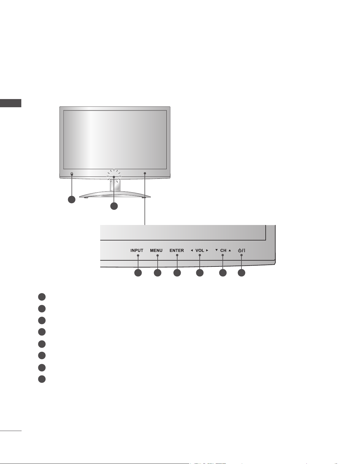
FRONT PANEL CONTROLS
■ This is a simplified representation of the side panel. The image shown may be somewhat different
from your set.
PREPARATION
1
8
1
Remote Control Sensor
INPUT Button
2
MENU Button
3
4
ENTER Button
VOLUME Button
5
CHANNEL Button
6
Power Button
7
Power Indicator
8
Lighting On: Turned on
Lighting Off: Turned off
Note: You can adjust Power indicator in the OPTION menu.
76532 4
4
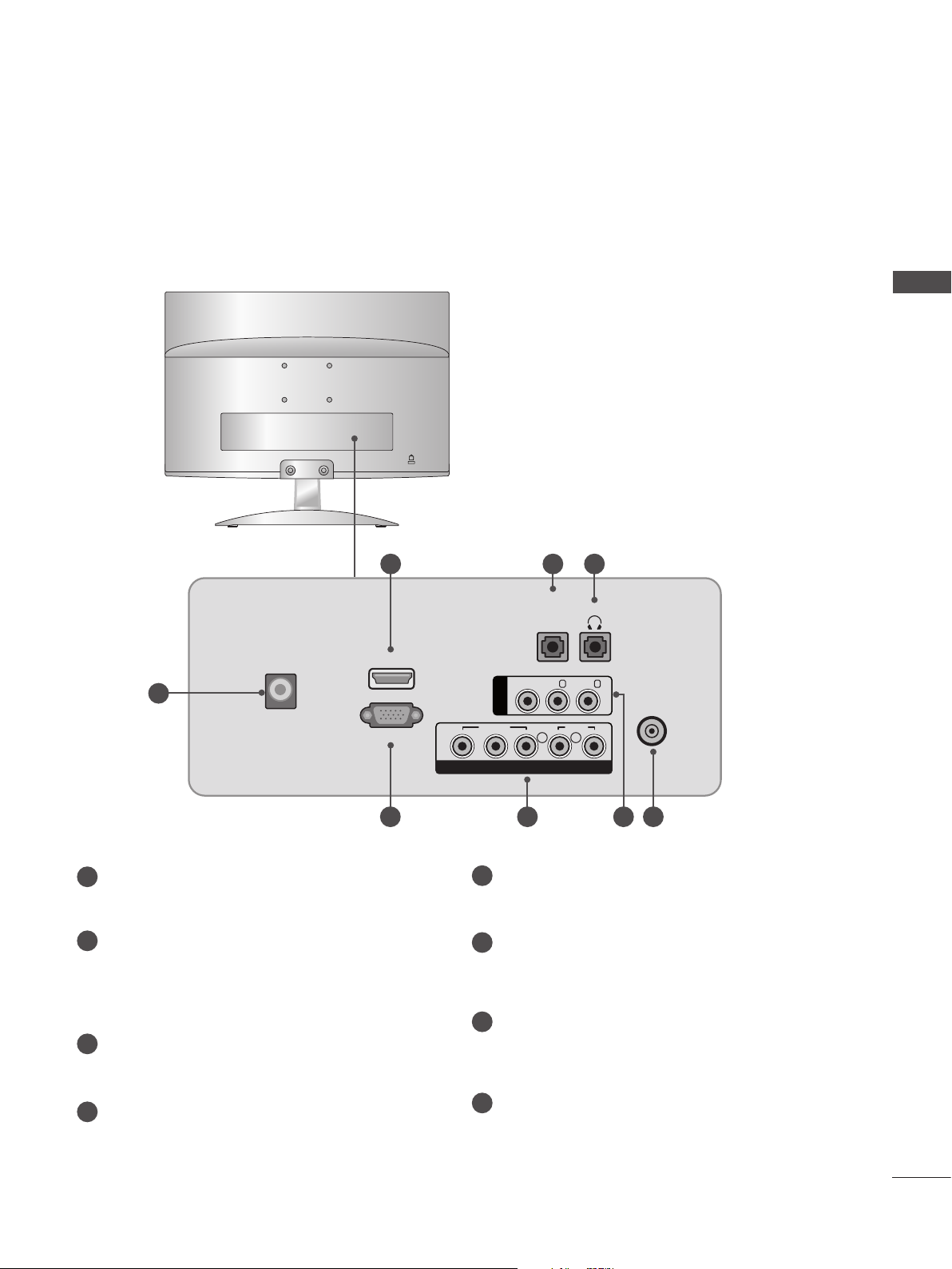
BACK PANEL INFORMATION
■ This is a simplified representation of the back panel. The image shown may be somewhat different
from your set.
2 3 4
AUDIO
H / P
IN
(RGB)
PREPARATION
HDMI IN
1
DC - IN
RGB IN (PC)
5 7
DC ADAPTER PORT
1
Connect to the power jack.
2
HDMI INPUT
Connect a HDMI signal to HDMI IN.
Or DVI (VIDEO) signal to HDMI IN with DVI to
HDMI cable.
3
RGB AUDIO INPUT
Connect the audio from a PC.
HEADPHONE SOCKET
4
Plug the headphone into the headphone socket.
VIDEO
Y PBP
COMPONENT IN
5
RGB INPUT (PC)
Connect the output from a PC.
COMPONENT INPUT
6
Connect a component video/audio device to
these jacks.
AV(AUDIO/VIDEO) INPUT
7
Connect audio/video output from an external
device to these jacks.
8
ANTENNA / CABLE INPUT
Connect over-the-air signals to this jack.
AV IN
VIDEO
R
(MONO) L -
AUDIO
L R
AUDIO
- R
ANTENNA /
CABLE IN
86
5
PREPARATION
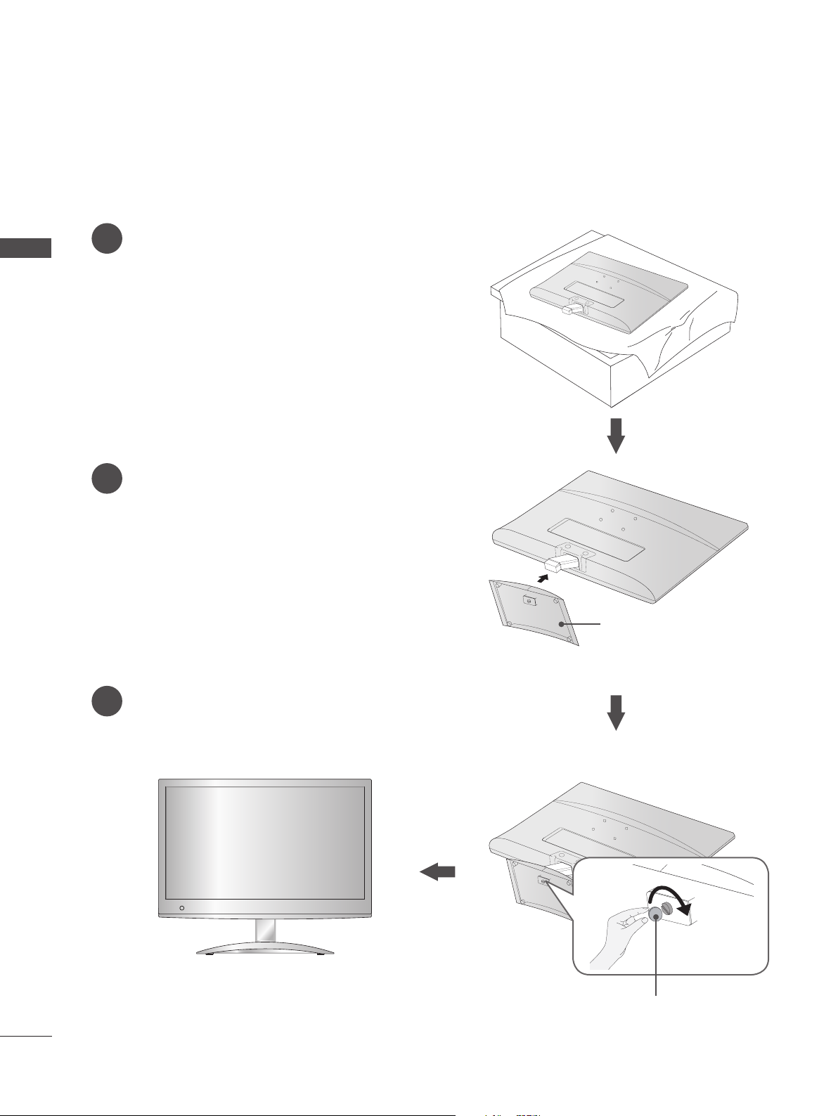
STAND INSTALLATION
■ The image shown may be somewhat different from your set.
Carefully place the product screen side down on a
1
cushioned surface that will protect the set and its
PREPARATION
screen from damage.
Insert the Stand Base into the product.
2
Use a Coin on the bottom of the stand base
3
and turn the screw clockwise to tighten.
Stand Base
Coin
6
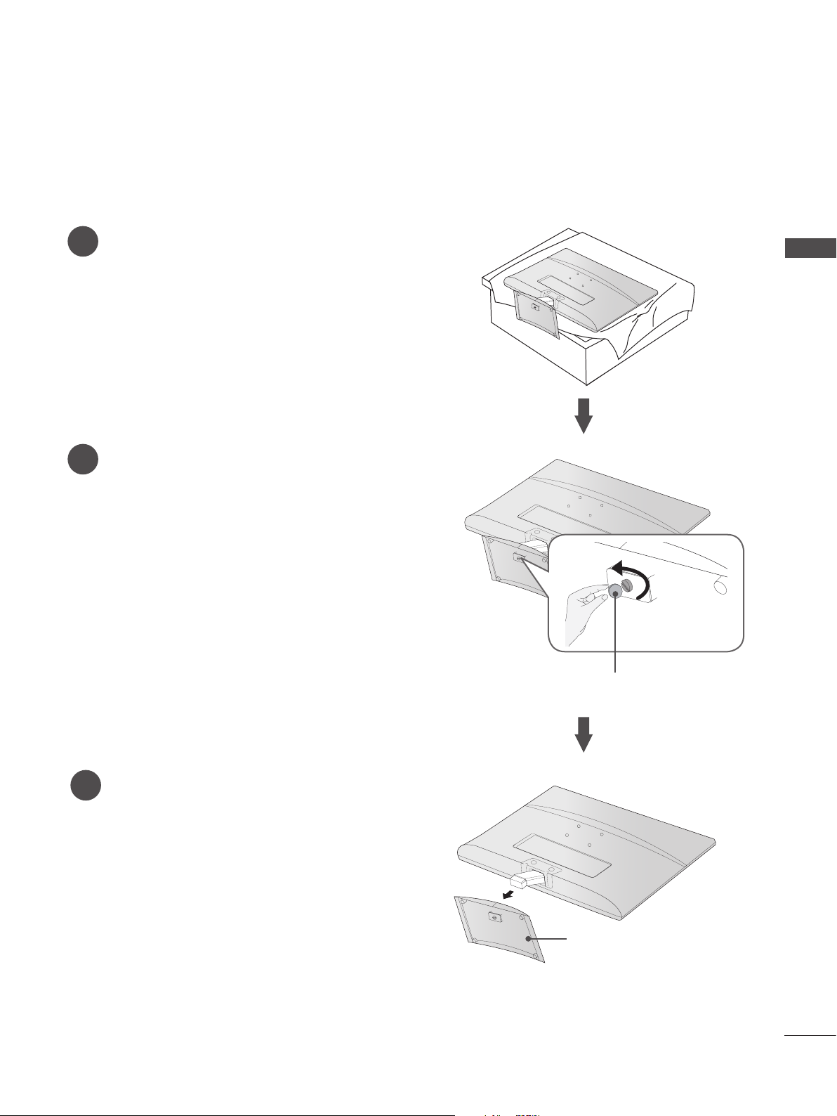
DETACHING STAND
■ The image shown may be somewhat different from your set.
Place the set screen side down on a cushion
1
or soft cloth.
Detach the stand base from the set by turning the
2
screw to the left with a Coin.
PREPARATION
Pull the Stand Base.
3
Coin
Stand Base
7
PREPARATION
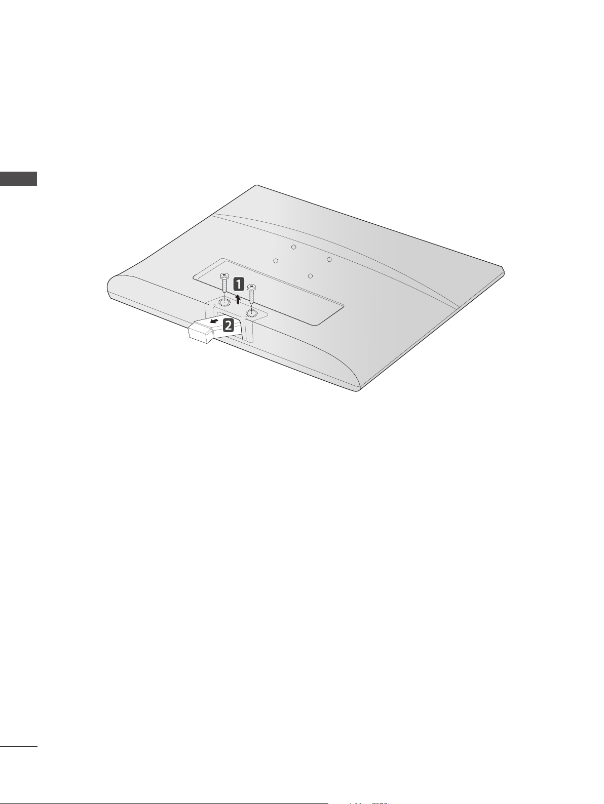
DETACHING STAND BODY
■ The image shown may be somewhat different from your set.
■ Remove the Stand Body in the same way as the following when using it as a Wall Hook.
PREPARATION
1. Remove the screw 2 point.
2. Pull the stand body.
8
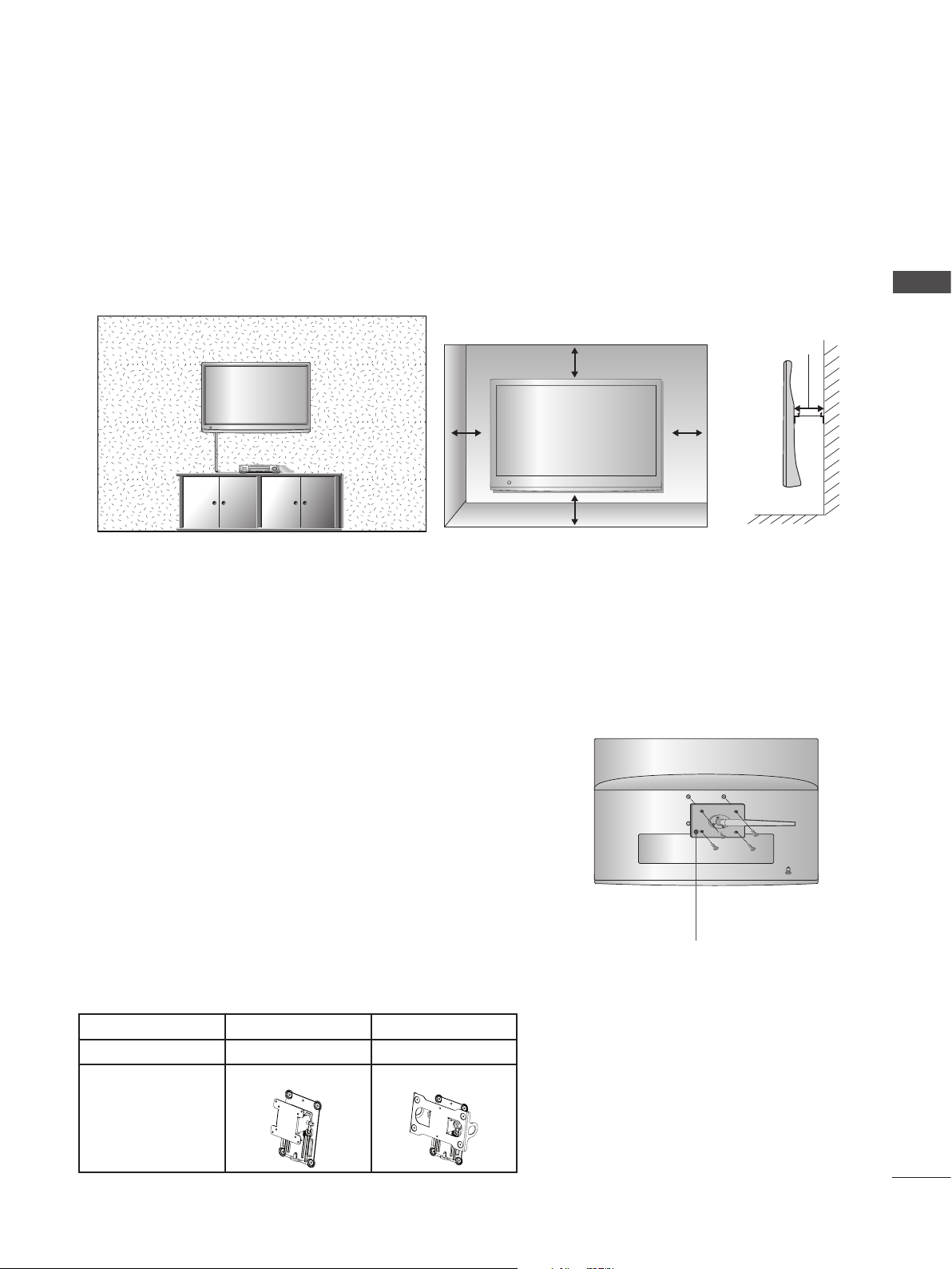
WALL MOUNT: HORIZONTAL INSTALLATION
■ The image shown may be somewhat different from your set.
For proper ventilation, allow a clearance of 10 cm on each side and from the wall. Detailed installation
instructions are available from your dealer, see the optional Tilt Wall Mounting Bracket Installation and
Setup Guide.
PREPARATION
10 cm
10 cm10 cm
10 cm
If you intend to mount the set to a wall, attach Wall mounting interface (optional parts) to the back of the set.
When you install the set using the wall mounting interface (optional parts), attach it carefully so it will not drop.
1. Be sure to use screws and a wall mount that meet VESA standards.
2. Using screws longer than those recommended might damage the product.
3. Using screws that do not meet VESA standards might either damage the product or result in it coming away from the wall. We will not be held responsible for any damage resulting from failure to
follow these instructions.
4. VESA compatible only with respect to screw mounting
interface dimensions and mounting screw specifications.
5. Please use VESA standard as below.
5-1) 784.8 mm (30.9 inch) and under
* Wall Mount Pad Thickness : 2.6 mm
* Screw : Φ 4.0 mm x Pitch 0.7 mm x Length 10 mm
5-2) 787.4 mm (31.0 inch) and above
* Please use VESA standard wall mount pad and screws.
10 cm
< Screw Mounting Interface Dimensions >
Model M1950A M2550A
VESA ( A x B) 75 x 75 200 x 100
Wall mount
bracket(optional)
RW120 RW240
Wall Mount Pad
9
PREPARATION
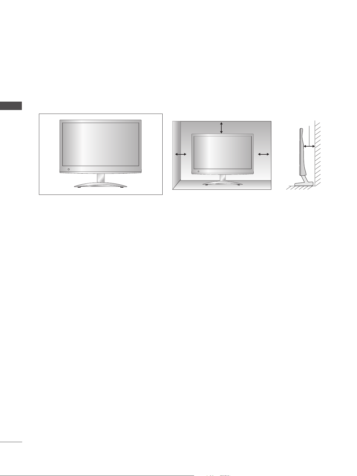
DESKTOP PEDESTAL INSTALLATION
For proper ventilation, allow a clearance of 10 cm on each side and from the wall.
PREPARATION
10 cm
10 cm 10 cm
10 cm
10
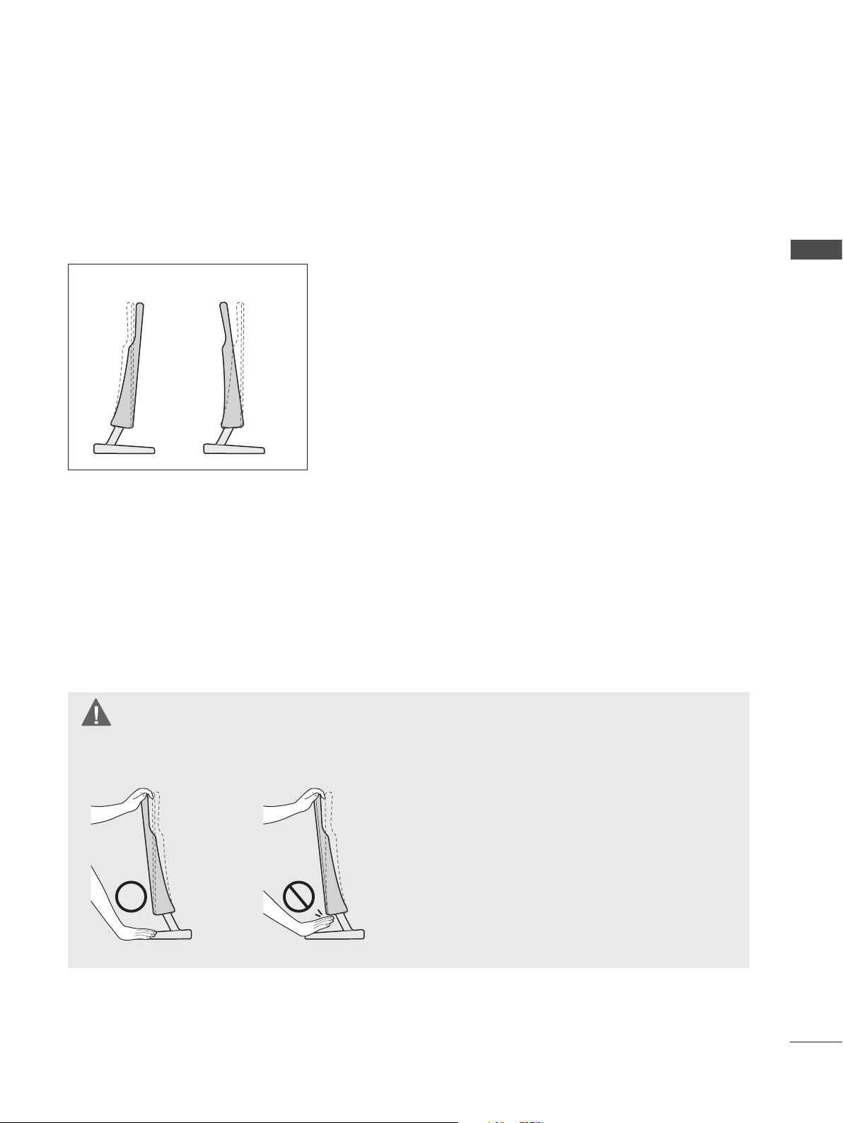
POSITIONING YOUR DISPLAY
■ The image shown may be somewhat different from your set.
Adjust the position of the panel in various ways for maximum comfort.
* Tilt range
-5° 10°
LOCATION
PREPARATION
Position your set so that no bright light or sunlight falls directly onto the screen. Care should be taken
not to expose the set to any unnecessary vibration, moisture, dust or heat. Also, ensure that the set is
placed in a position to allow a free flow of air. Do not cover the ventilation openings on the back cover.
WARNING
When adjusting the angle of the screen, do not put your finger(s) in between the head of the monitor and the stand body or woofer. You can hurt your finger(s).
11

PREPARATION
KENSINGTON SECURITY SYSTEM
- The product is equipped with a Kensington Security System connector on the back panel. Connect the
Kensington Security System cable as shown below.
- For detailed installation and use of the Kensington Security System, refer to the user’s guide provided
with the Kensington Security System.
PREPARATION
- For further information, visit http://www.kensington.com. Kensington sells security systems for expen-
sive electronic equipment such as notebook PCs and LCD projectors.
NOTE
- The Kensington Security System is an optional accessory.
NOTES
a. If the product feels cold to the touch, there may be a small “flicker” when it is turned on.
This is normal, there is nothing wrong with product.
b. Some minute dot defects may be visible on the screen, appearing as tiny red, green, or blue spots.
However, they have no adverse effect on the monitor’s performance.
c. Avoid touching the LCD screen or holding your finger(s) against it for long periods of time.
Doing so may produce temporary distortions on the screen.
12
EXTERNAL EQUIPMENT SETUP
■ To prevent damage do not connect to the mains outlet until all connections are made between the devices.
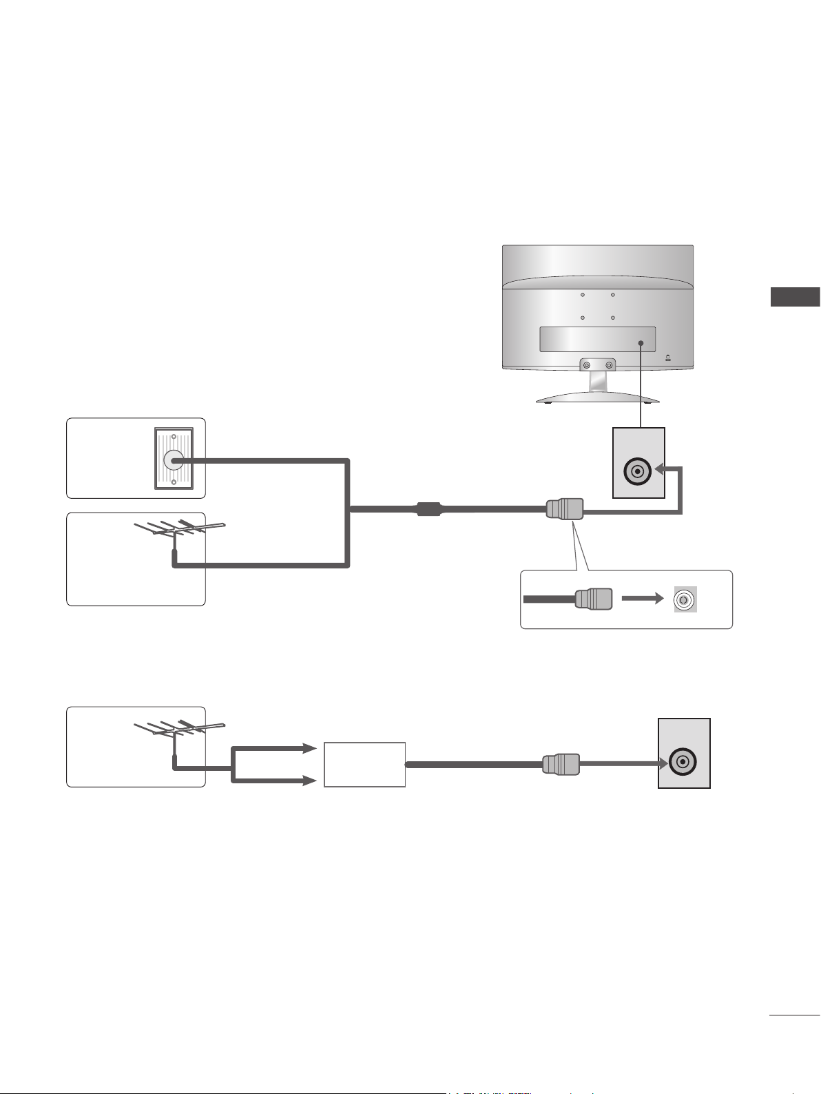
ANTENNA CONNECTION
■ For optimum picture quality, adjust antenna direction.
■ An antenna cable and converter are not included with the SET.
EXTERNAL EQUIPMENT SETUP
Wall
Antenna
Socket
Outdoor
Antenna
Antenna
Multi-family Dwellings / Apartments
(Connect to wall antenna socket)
RF Coaxial Wire (75 Ω)
Single-family Dwellings / Houses
(Connect to wall jack for outdoor antenna)
UHF
Signal
Amplifier
VHF
ANTENNA /
CABLE IN
ANTENNA /
CABLE IN
■ In poor signal areas, to get better picture quality, install a signal amplifier to the antenna as shown above.
■ If signal needs to be split for two sets, use an antenna signal splitter for connection.
13
EXTERNAL EQUIPMENT SETUP
AUDI
O
IN
(
RGB
)
H / P
H
DMI I
N
ANTENNA /
C
ABLE I
N
ANTENNA /
CABLE IN
O
(MONO) L -
O
- R
IN
■ To avoid damaging any equipment, never plug in any power cords until you have finished connecting
all equipment.
■ The image shown may be somewhat different from your set.
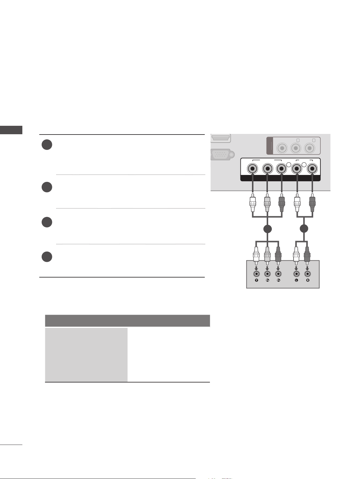
HD RECEIVER SETUP
When connecting with a component cable
EXTERNAL EQUIPMENT SETUP
Connect the video outputs (Y, PB, PR) of the digital
1
set-top box to the COMPONENT IN VIDEO jacks on
the set.
Connect the audio output of the digital set-top box
2
to the COMPONENT IN AUDIO jacks on the set.
Turn on the digital set-top box. (Refer to the owner’s
3
manual for the digital set-top box.)
Select COMPONENT input source using the INPUT
4
button on the remote control.
Support resolution
Signal Component
GB IN (PC)
Y P
VIDE
VIDEO
B
P
R
COMPONENT IN
1
AUDIO
L R
AUDI
2
14
480i / 576i O
480p / 576p O
720p O
1080i / 1080p O
!
AUDI
O
(
RGB
)
H / P
DMI I
N
GB IN (PC)
ANTENNA /
C
ABLE I
N
ANTENNA /
CABLE IN
VIDEO
Y P
B
P
R
L R
AUDIO
COMPONENT IN
VIDE
O
(MONO) L -
AUDI
O
- R
IN
AUDI
O
IN
(
RGB
)
H / P
ANTENNA /
C
ABLE I
N
O
Y
PBP
R
R
AUDIO
N
O
(MONO) L -
O
- R
AV
IN
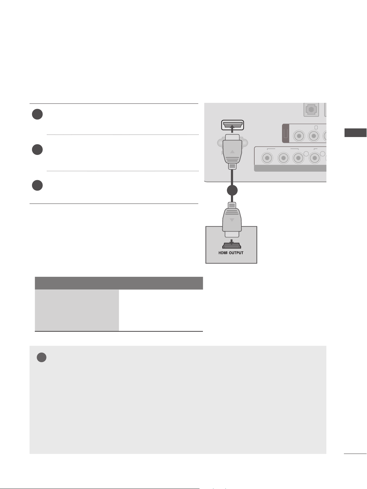
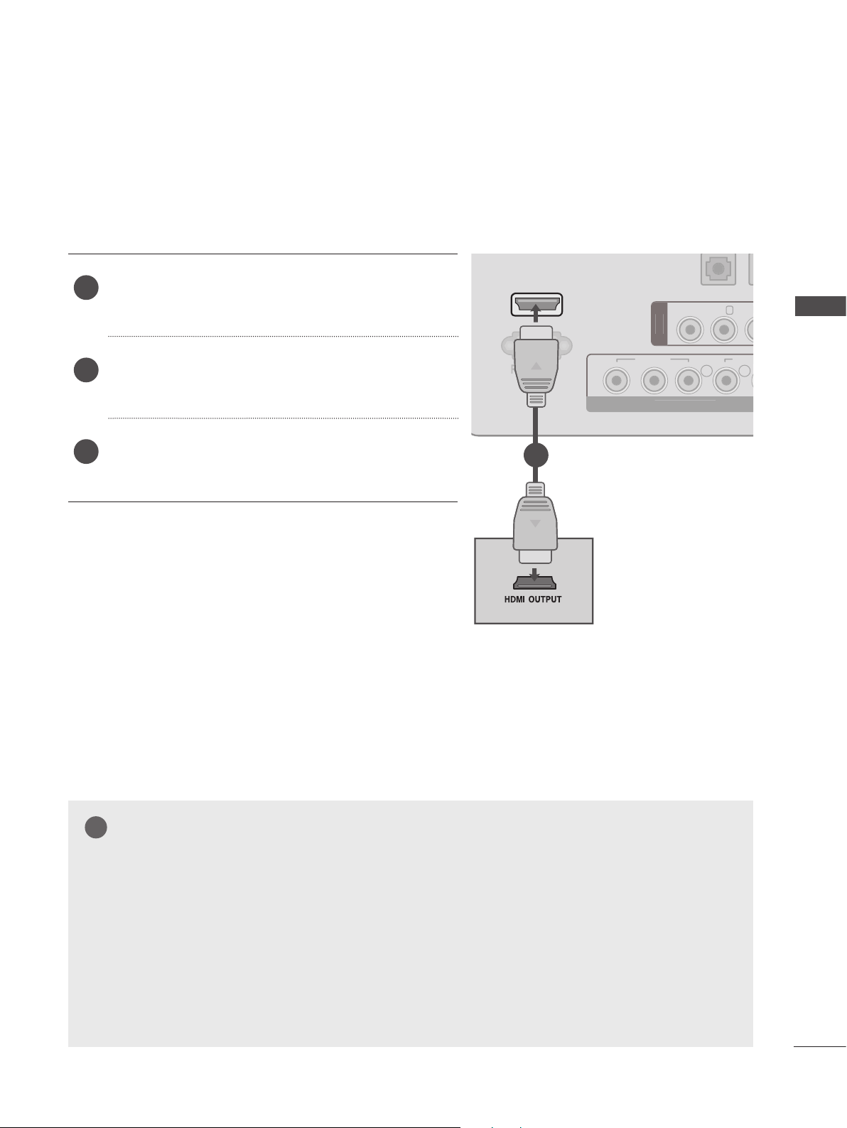
Connecting a set-top box with a HDMI cable
Connect the HDMI output of the digital set-top box
1
to the HDMI IN jack on the set.
2
Select HDMI input source using the INPUT button
on the remote control.
Turn on the digital set-top box. (Refer to the owner’s
3
manual for the digital set-top box.)
Support resolution
Signal HDMI
HDMI IN
GB IN (PC)
1
VIDE
VIDE
COMPONENT I
AUDI
EXTERNAL EQUIPMENT SETUP
480p / 576p O
720p O
1080i / 1080p O
NOTE
►Set can receive the video and audio signal simultaneously with using a HDMI cable.
►If the digital set-top box supports Auto HDMI function, the output resolution of the source device
will be automatically
►Check out the resolution setting of external device is 1920 X 1080P for getting best picture
quality.
►We recommend less than 10 m for HDMI cable.
►Check that your HDMI cable is High Speed HDMI Cable. If the HDMI cables are not High
Speed HDMI Cable, flickering or no screen display can result. Please use the High Speed
HDMI Cable.
set
to 1920 x 1080p.
15
EXTERNAL EQUIPMENT SETUP
AUDI
O
(
RGB
)
H / P
DMI I
N
ANTENNA /
C
ABLE I
N
ANTENNA /
CABLE IN
O
(MONO) L -
O
- R
IN
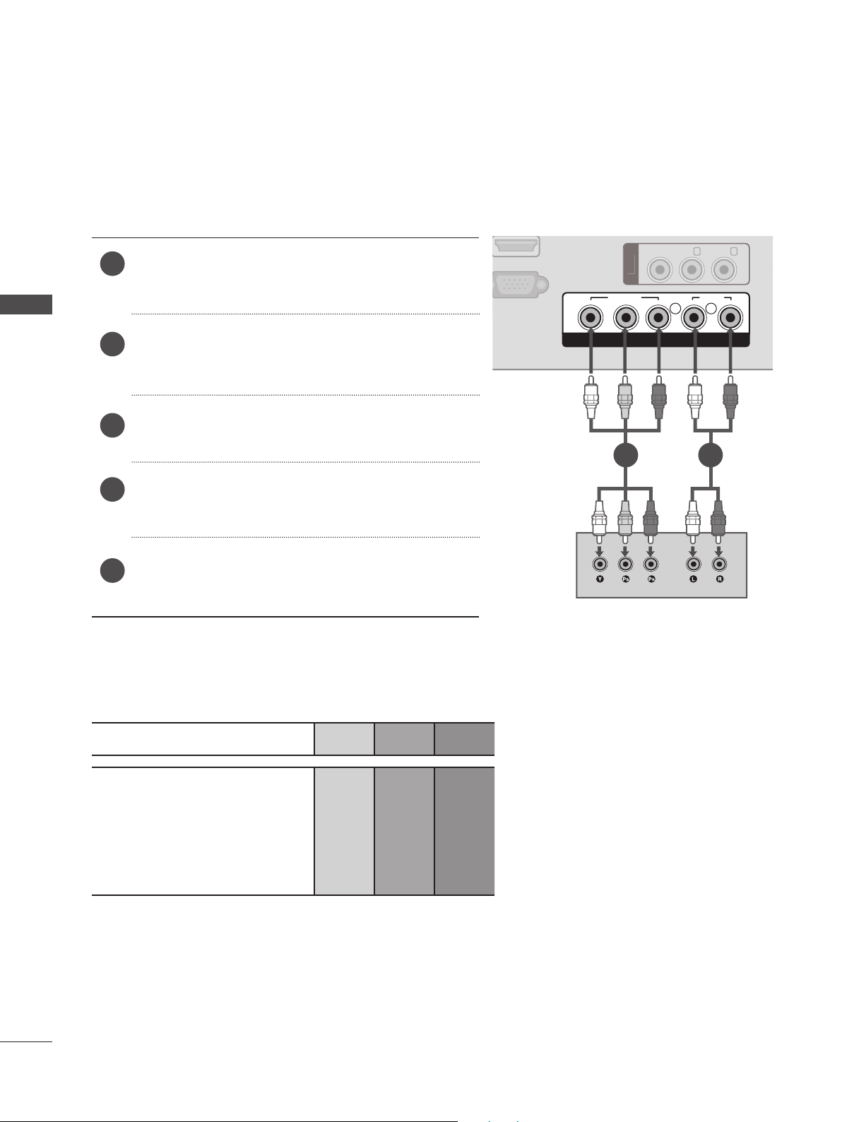
DVD SETUP
Connecting with a component cable
EXTERNAL EQUIPMENT SETUP
Connect the video outputs (Y, PB, PR) of the DVD
1
to the COMPONENT IN VIDEO jacks on the set.
Connect the audio outputs of the DVD to the
2
COMPONENT IN AUDIO jacks on the set.
Turn on the DVD player, insert a DVD.
3
Select Component using the INPUT on the remote
4
control.
Refer to the DVD player’s manual for operating
5
instructions.
GB IN (PC)
Y P
VIDE
VIDEO
B
P
R
L R
COMPONENT IN
1 2
AUDI
AUDIO
16
Port matching
Connect between the port of TV and the port of DVD, As below chart.
Port name of this set Y P
Y P
B
B
P
R
P
R
Y B-Y R-Y
Port name of DVD
Y Cb Cr
Y Pb Pr
!
AUDI
O
IN
(
RGB
)
H / P
DMI I
N
GB IN (PC)
ANTENNA /
C
ABLE I
N
ANTENNA /
CABLE IN
VIDEO
Y P
B
P
R
L R
AUDIO
COMPONENT IN
VIDE
O
(MONO) L -
AUDI
O
- R
AV
IN
AUDI
O
(
RGB
)
H / P
ANTENNA /
C
ABLE I
N
O
Y
PBP
R
R
AUDIO
N
O
(MONO) L -
O
AV
IN
Connecting with a HDMI cable
1
Connect the HDMI output of the DVD to the HDMI
IN jack on the set.
HDMI IN
VIDE
AUDI
EXTERNAL EQUIPMENT SETUP
Select HDMI input source using the INPUT button
2
on the remote control.
Refer to the DVD player’s manual for operating
3
instructions.
GB IN (PC)
1
VIDE
COMPONENT I
NOTE
►Set can receive the video and audio signal simultaneously with using a HDMI cable.
►If the digital set-top box supports Auto HDMI function, the output resolution of the source device
will be automatically set to 1920 x 1080p.
►If the digital set-top box player does not support Auto HDMI, you need to set the output resolu-
tion appropriately.
►To get the best picture quality, adjust the output resolution of the source device to 1920 x 1080p .
►We recommend less than 10 m for HDMI cable.
►Check that your HDMI cable is High Speed HDMI Cable. If the HDMI cables are not High
Speed HDMI Cable, flickering or no screen display can result. Please use the High Speed
HDMI Cable.
17
EXTERNAL EQUIPMENT SETUP
AUDI
O
(
RGB
)
H / P
HDMI IN
R
GB IN (PC)
ANTENNA /
C
ABLE I
N
VIDE
O
L
R
AUDIO
COMPONENT I
N
VIDEO
(MONO) L -
AUDIO
- R
AV IN
O
IN
(
)
H / P
L
R
AUDIO
O
N
O
(MONO) L -
O
L
R
S-VIDEO
VIDEO
OUTPUT
SWITCH
ANT IN
ANT OUT
AUDI
O
IN
(
RGB
)
H / P
C
N
O
Y
PBP
R
L
R
AUDIO
N
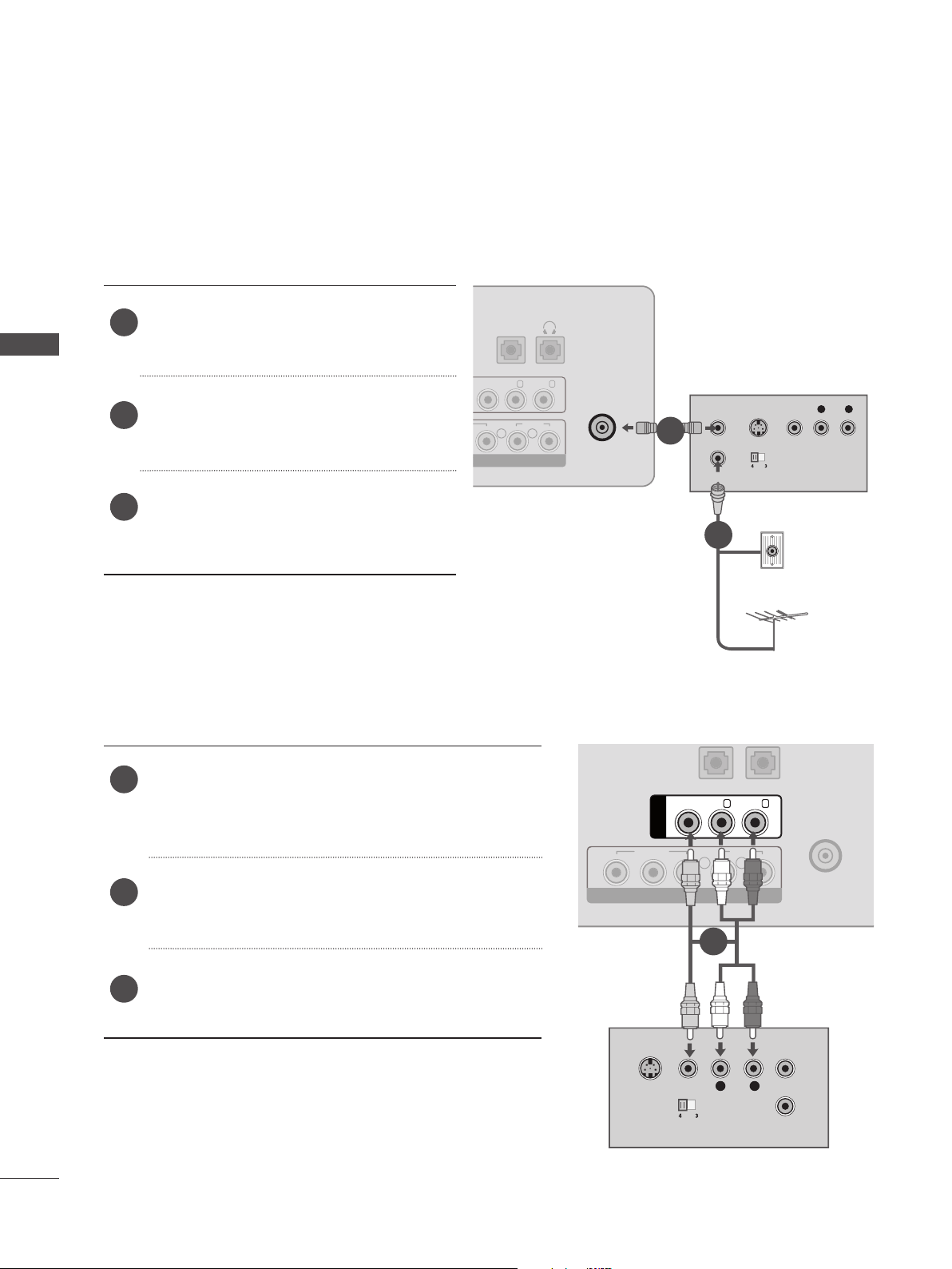
VCR SETUP
■ To avoid picture noise (interference), allow adequate distance between the VCR and SET.
Connecting with a RF cable
EXTERNAL EQUIPMENT SETUP
Connect the ANT OUT socket of the VCR
1
to the ANTENNA IN socket on the set.
Connect the antenna cable to the ANT
2
IN socket of the VCR.
Press the PLAY button on the VCR and
3
match the appropriate program between
the SET and VCR for viewing.
Connecting with a RCA cable
VIDE
NENT I
AUDI
RGB
AUDI
ANTENNA /
CABLE IN
L
ANT OUT
S-VIDEO VIDEO
R
1
OUTPUT
ANT IN
SWITCH
2
Wall Jack
Antenna
18
Connect the AUDIO / VIDEO jacks between SET
1
and VCR. Match the jack colors (Video = yellow,
Audio Left = white, and Audio Right = red)
Insert a video tape into the VCR and press PLAY.
2
(Refer to the VCR owner’s manual.)
Select AV input source using the INPUT button on
3
the remote control.
S-VIDEO
AV IN
VIDE
COMPONENT I
VIDEO
VIDEO
OUTPUT
SWITCH
(MONO) L -
1
L
AUDIO
- R
R
ANT OUT
ANT IN
ANTENNA /
ABLE I
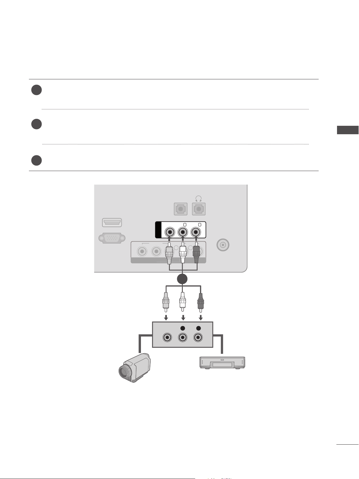
OTHER A/V SOURCE SETUP
O
(
)
H / P
R
C
N
O
Y
PBP
R
L
R
AUDIO
N
Connect the AUDIO / VIDEO jacks between SET and external equipment. Match the jack
1
colors. (Video = yellow, Audio Left = white, and Audio Right = red)
Select AV input source using the INPUT button on the remote control.
2
If connected to AV IN, select AV input source.
Operate the corresponding external equipment. Refer to external equipment operating guide.
3
AUDI
RGB
(MONO) L -
AUDIO
- R
ANTENNA /
ABLE I
GB IN (PC)
VIDEO
AV IN
VIDE
EXTERNAL EQUIPMENT SETUP
Camcorder
COMPONENT I
VIDEO
1
L R
Video Game Set
19

EXTERNAL EQUIPMENT SETUP
!
H / P
ANTENNA /
C
ABLE I
N
O
Y
PBPRL
R
AUDIO
N
O
(MONO) L -
O
- R
AV
IN
PC SETUP
When connecting with a D-sub 15 pin cable
Connect the signal cable from the monitor output
1
socket of the PERSONAL COMPUTER to the PC
EXTERNAL EQUIPMENT SETUP
input socket of the set.
DMI I
AUDIO
IN
(RGB)
VIDE
AUDI
Connect the audio cable from the PC to the AUDIO
2
IN (RGB) sockets of the set.
Press the INPUT button to select RGB PC.
3
Switch on the PC, and the PC screen appears on
4
the set. The set can be operated as a PC monitor.
RGB IN (PC)
RGB OUTPUT
VIDE
COMPONENT I
21
AUDIO
NOTE
►Connect the signal input cable and tighten it by turning
the screws clockwise.
►User must use VGA cable (D-sub 15 pin cable) with ferrite cores to maintain standard compli-
ance for the product.
20

BACK COVER FOR WIRE ARRANGEMENT
Tie cables together for better cable management as shown in the illustration below.
EXTERNAL EQUIPMENT SETUP
21

EXTERNAL EQUIPMENT SETUP
SUPPORTED DISPALY RESOLUTION
RGB[PC] mode
<M1950A> <M2550A>
EXTERNAL EQUIPMENT SETUP
Resolution
640 x 480 31.469 59.94
800 x 600 37.879 60.317
1024 x 768 48.363 60.0
1280 x 720 47.77 59.85
1360 x 768 47.71 60.02
HDMI[DTV] mode
Resolution
720 x 480 15.75 60.00
Horizontal
Frequency(kHz)
Horizontal
Frequency(kHz)
Vertical
Frequency(Hz)
Frequency(Hz)
Vertical
Resolution
640 x 480 31.469 59.94
800 x 600 37.879 60.317
1024 x 768 48.363 60.0
1152 x 864 54.34 60.05
1280 x 960 60 60
1280 x 1024 63.981 60.02
1680 x 1050 64.674 59.883
1680 x 1050 65.290 59.954
1920 x 1080 67.5 60
Horizontal
Frequency(kHz)
Vertical
Frequency(Hz)
22
720 x 480 15.73 59.94
720 x 576 15.625 50.00
720 x 480 31.47 59.94
720 x 480 31.50 60.00
720 x 576 31.25 50.00
1280 x 720 44.96 59.94
1280 x 720 45.00 60.00
1280 x 720 37.50 50.00
1920 x 1080 33.72 59.94
1920 x 1080 33.75 60.00
1920 x 1080 28.125 50.00
1920 x 1080 67.432 59.94
1920 x 1080 67.5 60
1920 x 1080 56.250 50

WATCHING TV / CHANNEL CONTROL
REMOTE CONTROL KEY FUNCTIONS
When using the remote control, aim it at the remote control sensor on the set.
TV/PC
MUTE FCR
POWER
MEMORY/ERASE
A.PROGMTS
1 2 3
4 5 6
7 8 9
0
CH
ENTER
VOL VOL
CH
INPUT
CAPTION
POWER
TV/PC
INPUT
MTS
A.PROG
MEMORY/
ERASE
CAPTION
0 to 9 number
button
MUTE
Switches the set on from standby or off to standby.
Selects TV or PC mode.
Cycles through external input modes.
Press repeatedly to select Mono,Stereo, SAP sound
tone. But Stereo, SAP mode are available only if
included on the broadcast signal.
Auto Channel tuning Button.
User can do manual channel selection and store or
erase individual channels.
Select a closed caption.
Off ➡ Mode1 ➡ Mode2 ➡ Text1 ➡ Text2
(► p.51)
Selects a channel.
Selects numbered items in a menu.
Turn the sound on or off.
WATCHING TV / CHANNEL CONTROL
MENU REVIEW
APC DASP
SLEEP
ARC/
FCR
Favorite channel button.
*
23

WATCHING TV / CHANNEL CONTROL
TV/PC
POWER
INPUT
THUMBSTICK
Allows you to navigate the on-screen menus and
adjust the system settings to your preference.
MEMORY/ERASE
A.PROGMTS
1 2 3
CAPTION
-
-Left/Right
ENTER
Selects a channel.
Adjusts the volume.
Accepts your selection or displays the current mode.
Up/Down
WATCHING TV / CHANNEL CONTROL
4 5 6
7 8 9
0
MUTE FCR
CH
ENTER
VOL VOL
CH
MENU REVIEW
APC DASP
SLEEP
ARC/
*
MENU
REVIEW
SLEEP
APC
DASP
ARC/
Selects a menu.(► p.26)
Turn to the last channel viewed.
Sets the sleep timer.
Auto Picture Control.
Press repeatedly to select Standard, Vivid or Cinema
mode.
Digital Auto Sound Processing.
Use this button to select the sound tone.
Press repeatedly to select Stantard, Music or
Cinema.
Selects your desired picture format.(► p.30)
*
24
Installing Batteries
■ Open the battery compartment cover on the back side and install
the batteries matching correct polarity (+with +,-with -
■ Install two 1.5 V AAA batteries. Don’t mix old or used batteries with
new ones.
■ Close cover.
■ To remove the batteries, perform the installation actions in reverse.
)

TURNING ON THE SET
When using the remote control, aim it at the remote control sensor on the set.
Firstly, connect the power cord correctly.
1
At this stage, the set switches to standby mode.
■ In standby mode to turn set on, press the button on the set or press the POWER buttons
on the remote control and the set will switch on.
INSTALLATION GUIDE
If the OSD (On Screen Display) is displayed on the screen after turning on the set, you can adjust
1
the Language, Auto Tuning.
Note:
a. It will automatically disappear after approx. 40 seconds unless a button is pressed.
b. If you close without completing the initial setting, the Instal lation Guide menu can be displayed
again.
CHANNEL SELECTION
Press the ▲/▼ or NUMBER buttons to select a channel number.
1
WATCHING TV / CHANNEL CONTROL
VOLUME ADJUSTMENT
Press the ◄ / ► button to adjust the volume.
1
If you wish to switch the sound off, press the MUTE button.
2
You can cancel the Mute function by pressing the MUTE, ◄ / ►, MTS or DASP.
3
25

WATCHING TV / CHANNEL CONTROL
!
ON SCREEN MENUS SELECTION AND ADJUSTMENT
If set design may changed, The shown image may be different with your set.
Press the MENU button and then ▲/▼ button to display each menu.
1
Press the ► button and then ▲/▼ button to select a menu item.
2
Change the setting of an item in the sub or pull-down menu with ◄ / ► button.
3
WATCHING TV / CHANNEL CONTROL
You can move to a higher level menu by pressing the ENTER(ꔉ) button.
Setup
Auto Tuning
Manual Tuning
Favorite Channel
▲▼◄► ꔉ MENU
Setup MENU
Option
Language
Key Lock
Caption/Text
DDC-CI
Power Indicator
Mode Setting
Factory Reset
▲▼◄► ꔉ MENU
Option MENU
Picture
Aspect Ratio
Picture Mode
• Backlight 100
• Contrast 100
• Brightness 50
• Sharpness 70
• Color 70
• Tint 0
▲▼◄► ꔉ MENU ▲▼◄► ꔉ MENU
▼
Audio
Sound Mode
• Treble 50
• Bass 50
• Reset
Auto Volume
Balance 0
Picture MENU Audio MENU
Time
Clock
Off Time
On Time
Sleep Timer
Auto Sleep
▲▼◄► ꔉ MENU
Time MENU
NOTE
►The OSD (On Screen Display) function enables you to adjust the screen status conveniently
since it provides graphical presentation.
►In this manual, the OSD (On Screen Display) may be different from your set’s because it is just
example to help the set operation.
26

AUTO TUNING
This TV is able to store 181channel (TV channel:2 to 69,CATV channel:1,14 to 125).
If you attempt below, automatically search for TV channels that are available in your area.
Setup
Press the MENU button and then ▲ / ▼ button to
1
select the Setup menu.
Press the ► button and then ▲ / ▼ button to select
2
Auto Tuning.
Press the ► button to begin auto tunnig.
3
All receivable stations are stored.
To stop auto tuning, press the menu button.
Setup
V Auto Tuning
Auto Tuning ►
Manual Tuning
Favorite Channel
Auto Tuning
Manual Tuning
Favorite Channel
▲▼◄► ꔉ MENU
To Start
WATCHING TV / CHANNEL CONTROL
1
Press the MENU button to move to the previous
4
menu screen.
▲▼◄► ꔉ MENU
2
Auto Tuning
TV
35 43%
MENU Stop
3
27

WATCHING TV / CHANNEL CONTROL
MANUAL TUNING
You can add or delete channels from the channel scan manually.
Press the MENU button and then ▲ / ▼ button to
1
select the Setup menu.
Setup
Auto Tuning
Manual Tuning
Favorite Channel
WATCHING TV / CHANNEL CONTROL
Press the ► button and then ▲ / ▼ button to select
2
Manual Tuning.
▲▼◄► ꔉ MENU
1
Press the ► button and then ▲ / ▼button to select
3
Channel number.
Press the ▲ / ▼ button to select Erase .
4
Press the ▲ / ▼ button to select Fine. (Normally
5
fine tuning is only necessary if reception is poor.)
Press the MENU button to move to the previous
6
Setup
Auto Tuning
Manual Tuning
Manual Tuning ►
Favorite Channel
▲▼◄► ꔉ MENU
Setup
Auto Tuning
Manual Tuning
Manual Tuning ►
Favorite Channel
TV 55
Erase
Fine 0
TV 55
TV 55
Erase
Fine 0
2
menu screen.
▲▼◄► 0 - 9 ꔉ MENU
55443
Setup
Auto Tuning
Manual Tuning
Manual Tuning ►
Favorite Channel
TV 55
Erase
Erase
Fine 0
28
▲▼◄► ꔉ MENU
3

FAVORITE CHANNEL
This function lets you select your favorite channel directly.
Repeatedly press the FCR button to select stored favorite channel.
Press the MENU button and then ▲ / ▼ button to
1
select the Setup menu.
Setup
Auto Tuning
Manual Tuning
Favorite Channel
Press the ► button and then ▲ / ▼ button to select
2
Favorite Channel.
Press the ► button.
3
Press the ▲ / ▼ button to select - - - - - - - -.
4
Select a desired channel with the ◄ / ► button.
5
To store another channel, repeat steps 4 to 5.
6
You can store up to 8 channel.
Press the MENU button to move to the previous
7
menu screen.
▲▼◄► ꔉ MENU
Setup
Auto Tuning
Manual Tuning
Favorite Channel ►
FavoriteChannel
▲▼◄► ꔉ MENU
WATCHING TV / CHANNEL CONTROL
1
CATV 95
– – – – – – –
CATV 95
CATV 95
CATV 95
CATV 95
– – – – – – –
CATV 95
53 42
29

PICTURE CONTROL
!
PICTURE SIZE (ASPECT RATIO) CONTROL
You can watch the screen in various picture formats; 16:9, 4:3, Zoom1, Zoom2 and Just Scan.
If a fixed image is displayed on the screen for a long time, that fixed image may become imprinted on
the screen and remain visible.
You can adjust the enlarge proportion using ▲ / ▼ button.
This function works in the following signal.
You can adjust Aspect Ratio in the Picture menu.
1
• 16:9
The following selection will allow you to
adjust the picture horizontally, in linear proportion, to fill the entire screen(useful for
viewing 4:3 formatted DVDs).
16:9
• 4:3
The following selection will allow you to
PICTURE CONTROL
view a picture with an original 4:3 aspect
ration, black bars will appear on both the
left and right of the screen.
4 : 3
• Zoom 1
The following selection will allow you to
view the picture without any alteration,
while filling the entire screen. However, the
top and bot tom of the picture will be
cropped.
• Zoom 2
Choose Zoom 2 when you wish the picture
to be altered, both horizontally extended
and vertically cropped. The picture adopting
a compromise between alteration and
screen converage.
Zoom 2 ▲▼
• Just Scan
Following Selection will lead to you view the
picture of best quality without loss of original picture in high resolution image.
Just Scan
Zoom 1 ▲▼
NOTE
►You can only select 4:3,16:9 (Wide) in Component, HDMI mode.
►In HDMI/Component (over 720p)mode, Just Scan is available.
30

PRESET PICTURE SETTINGS
!
Preset Picture mode
Choose from Standard, Cinema or sRGB (only RGB PC).
Each input (TV,AV, Component, etc) remembers the custom setting you created.
Press the MENU button and then ▲ / ▼ button to
1
select the Picture menu.
Press the ► button and then ▲ / ▼ button to select
2
Picture mode.
Press the ► button and then ▲ / ▼ button to select
3
Vivid, Standard ,Cinema or sRGB.
Press the MENU button to move to the previous
4
menu screen.
Picture
Aspect Ratio
Picture Mode
Picture Mode ►
• Backlight 100
• Contrast 100
• Brightness 50
• Sharpness 70
• Color 70
• Tint 0
▲▼◄► ꔉ MENU
▼
Picture
Aspect Ratio
Picture Mode
• Backlight 100
• Contrast 100
• Brightness 50
• Sharpness 70
• Color 70
• Tint 0
▲▼◄► ꔉ MENU
▼
Vivid
Standard
Cinema
sRGB
1
PICTURE CONTROL
NOTE
■ In RGB PC mode, sRGB is available.
32
31

!
PICTURE CONTROL
MANUAL PICTURE ADJUSTMENT
Picture Mode-User Option
Backlight
Contrast
Brightness
Sharpness
Color
Tint
Press the MENU button and then ▲ / ▼ button to
1
select the Picture menu.
Press the ► button and then ▲ / ▼ button to select
2
Picture mode.
Adjust brightness by controlling Lamp brightness of LCD.
Adjust white levels in picture.
Adjust black level in the picture.
Adjust the sharpness of the edges of elements in the picture.
Adjust the amount of color in the picture.
Adjust the hue of the picture.
Picture
Aspect Ratio
Picture Mode
• Backlight 100
• Contrast 100
• Brightness 50
• Sharpness 70
• Color 70
• Tint 0
▲▼◄► ꔉ MENU
▼
1
Picture
Aspect Ratio
Picture Mode
Press the ► button and then ▲ / ▼ button to select
3
Vivid, Standard ,Cinema or sRGB.
PICTURE CONTROL
Press the ENTER button and then ▲ / ▼ button to
4
select the desired picture option (Backlight, Contrast,
Brightness, Sharpness, Color and Tint).
Picture Mode ►
• Backlight 100
• Contrast 100
• Brightness 50
• Sharpness 70
• Color 70
• Tint 0
▲▼◄► ꔉ MENU
▼
Vivid
Standard
Cinema
sRGB
32
Picture
Press the ◄ / ► button to make appropriate
5
adjustments.
Press the MENU button to move to the previous
6
menu screen.
Aspect Ratio
Picture Mode
• Backlight 100
• Backlight 100 ►
• Contrast 100
• Brightness 50
• Sharpness 70
• Color 70
• Tint 0
▲▼◄► ꔉ MENU
▼
▲
• Backlight 100
▼
Vivid
NOTE
■ If you change any value from default setting of sub menu in Picture mode, the words as ‘(User)’ at
right side of the picture mode selected is shown. It means the value of Picture mode is set by user.
3
2
5
4
►

Picture Mode-advance Option
!
You can calibrate the screen for each Picture Mode or set the video value according to the special
video screen.
You can set the video value differently for each input.
To reset to the factory default screen after making adjustments to each video mode, execute the
“Picture Reset” function for each Picture Mode.
Press the MENU button and then ▲ / ▼ button to
1
select the Picture menu.
Press the ► button and then ▲ / ▼ button to select
2
Advanced.
Press the ► button and then ▲ / ▼ button to select
3
Dynamic Contrast, Dynamic Color, Noise Reduction,
Black Level, Film Mode or Color Temperature.
Press the MENU button to move to the previous
4
menu screen.
Picture
Picture Mode
▲▼◄► ꔉ MENU
Picture
Picture Mode
• Backlight 100
• Contrast 100
• Brightness 50
• Sharpness 70
• Color 70
• Tint 0
• Advanced
• Advanced ►
▲▼◄► ꔉ MENU
Advanced
Dynamic Contrast
Dynamic Contrast ►
Dynamic Color
Noise Reduction
Black Level
Film Mode
Color Temperature
• Red 0
• Green 0
▲▼◄► ꔉ MENU
▲
▼
▼
▲
• Backlight 100
• Contrast 100
• Brightness 50
• Sharpness 70
• Color 70
• Tint 0
• Advanced
▼
1
PICTURE CONTROL
To Set
To Set
2
Off
Low
High
3
NOTE
■ At 1080i / p Dynamic Contrast, Dynamic Color, Noise Reduction is not enable.
33

PICTURE CONTROL
Dynamic Contrast / Dynamic Color / Noise Reduction
■ This feather is not working in “RGB PC” input or 1080p/i resolution.
Black Level ■ This feather is not working in “RGB PC” input.
Film Mode
Color Temperature
■ This feature operates only 480i/576i mode on “AV”, “TV” and “Component”
input.
■ Choose one of three automatic color adjustments. Set to warm to enhance
hotter colors such as red, or set to cool to see less intense col ors with more
blue.
■ It is enable to be controlled red, green, blue to adjust color details.
PICTURE CONTROL
34

PICTURE RESET
!
Settings of the selected picture modes return to the default factory settings.
Press the MENU button and then ▲/▼ button to
1
select the Picture menu.
Press the ► button and then ▲/▼ button to select
2
Picture Reset.
Press the ► button to initialize the adjusted value.
3
Press the MENU button to move to the previous
4
menu screen.
Picture
▲▼◄► ꔉ MENU
Picture
• Backlight 100
• Contrast 100
• Brightness 50
• Sharpness 70
• Color 70
• Tint 0
• Advanced
• Picture Reset
• Picture Reset ►
▲▼◄► ꔉ MENU
▲
• Backlight 100
• Contrast 100
• Brightness 50
• Sharpness 70
• Color 70
• Tint 0
• Advanced
• Picture Reset
▲
▼
OK
1
32
PICTURE CONTROL
NOTE
■ If there is the words ‘(User)’ at right side of the picture mode, when you execute “Picture reset”,
the words ‘(User)’ is disappear at right side of the picture mode.
35

PICTURE CONTROL
SCREEN SETUP (RGB [PC] mode only)
AUTO CONFIGURE
Sets to adjust the screen position, clock, and phase automatically. The displayed image may be unstable
for a few seconds while the configuration is in progress.
Press the MENU button and then use ▲/▼ button
1
to select the Picture menu.
Press the ► button and then use ▲/▼ button to
2
select Screen.
Press the ► button and then use ▲/▼ button to
3
select Auto Config.
Press the ENTER(ꔉ) button.
4
PICTURE CONTROL
Press the MENU button to move to the previous
5
menu screen.
Picture
Picture
• Contrast 100
• Brightness 50
• Sharpness 70
• Color 70
• Tint 0
• Advanced
• Picture Reset
Screen
Screen ►
▲▼◄► ꔉ MENU
▲
▼
Aspect Ratio
Picture Mode
• Backlight 100
• Contrast 100
• Brightness 50
• Sharpness 70
• Color 70
• Tint 0
▼
▲▼◄► ꔉ MENU
1
To set
2
36
Screen
Auto config
Auto Config. ►
Manual Config.
Reset
▲▼◄► ꔉ MENU
To Set
4
3

MANUAL CONFIGURE(Adjustment for screen Position)
!
Sets to adjust the screen position, clock, and phase manually.
Press the MENU button and then use ▲/▼ button
1
to select the Picture menu.
Press the ► button and then use ▲/▼ button to
2
select Screen.
Press the ► button and then use ▲/▼ button to
3
select Manual Config.
Press the ► button and then use ▲/▼ button to
4
select Phase, Clock, H-Position or V-Position.
(When the H-Position and V-Position be changed,
Value may differ from the aspect ratio.)
Picture
• Contrast 100
• Brightness 50
• Sharpness 70
• Color 70
• Tint 0
• Advanced
• Picture Reset
Screen
Screen ►
▲▼◄► ꔉ MENU
▲
▼
Picture
Aspect Ratio
Picture Mode
• Backlight 100
• Contrast 100
• Brightness 50
• Sharpness 70
• Color 70
• Tint 0
▼
▲▼◄► ꔉ MENU
1
PICTURE CONTROL
To set
2
Press the ◄ / ► button to make appropriate adjust-
5
ments.
Press the MENU button to move to the previous
6
menu screen.
NOTE
■ The aspect ratio make H-Position and V-Position Value different.
Screen
Auto config
Manual Config.
Manual Config. ►
Reset
▲▼◄► ꔉ MENU
Phase 8
Clock 50
H-Position 50
V-Position 50
4 5
3
37

PICTURE CONTROL
!
RESET (Recover to factory setting)
Restores the options to the default setting.
Press the MENU button and then use ▲/▼ button
1
to select the Picture menu.
Press the ► button and then use ▲/▼ button to
2
select Screen.
Press the ► button and then use ▲/▼ button to
3
select Reset.
Press the ► button.
PICTURE CONTROL
4
Press the MENU button to move to the previous
5
menu screen.
Picture
Picture
• Contrast 100
• Brightness 50
• Sharpness 70
• Color 70
• Tint 0
• Advanced
• Picture Reset
Screen
Screen ►
▲▼◄► ꔉ MENU
▲
▼
Aspect Ratio
Picture Mode
• Backlight 100
• Contrast 100
• Brightness 50
• Sharpness 70
• Color 70
• Tint 0
▼
▲▼◄► ꔉ MENU
1
To set
2
38
Screen
Auto Config.
Manual Config.
Reset
Reset ►
▲▼◄► ꔉ MENU
NOTE
■ The screen will be unstable for a few seconds while the “Reset” is in progress.
To Set
4
3

SELECTING RESOLUTION
This feature matches the resolution of PC between PC and TV manually for optimizing picture in “RGB
PC” input. This feature operate in that the vertical size of picture is 768 or 1050.
Picture
Press the MENU button and then use ▲/▼ button
1
to select the Picture menu.
Press the ► button and then use ▲/▼ button to
2
select Screen.
Press the ► button and then use ▲/▼ button to
3
select Resolution.
Press the MENU button to move to the previous
4
menu screen.
Picture
• Contrast 100
• Brightness 50
• Sharpness 70
• Color 70
• Tint 0
• Advanced
• Picture Reset
Screen
Screen ►
▲▼◄► ꔉ MENU
▲
▼
Aspect Ratio
Picture Mode
• Backlight 100
• Contrast 100
• Brightness 50
• Sharpness 70
• Color 70
• Tint 0
▼
▲▼◄► ꔉ MENU
1
To set
2
PICTURE CONTROL
<Vertical resolution : 768> <Vertical resolution : 1050>
Screen Screen
Auto config
Manual Config.
Resolution
Resolution ► Resolution ►
Reset
▲▼◄► ꔉ MENU ▲▼◄► ꔉ MENU
1024 x 768
1280 x 768
1360 x 768
1366 x 768
Auto config
Manual Config.
Resolution
Reset
1400 x 1050
1680 x 1050
3
39

SOUND CONTROL
PRESET SOUND SETTINGS - SOUND MODE
Choose from Standard, Music or Cinema.
Each input (TV,AV, Component, etc) remembers the custom setting you created.
Press the MENU button and then ▲/▼ button to
1
select the Audio menu.
Press the ► button and then ▲/▼ button to select
2
Sound Mode.
Press the ► button and then ▲/▼ button to select
3
Standard, Music or Cinema.
Press the MENU button to move to the previous
4
menu screen.
Audio
Sound Mode ►
Sound Mode
• Treble 50
• Bass 50
• Reset
Auto Volume
Balance 0
Audio
Sound Mode
• Treble 50
• Bass 50
• Reset
Auto Volume
Balance 0
▲▼◄► ꔉ MENU
1
Standard
Music
Cinema
▲▼◄► ꔉ MENU
SOUND CONTROL
32
40

SOUND SETTING ADJUSTMENT - USER MODE
!
Treble
Bass
Reset
Control sound level of high frequency like enhance or reducing.
Control of low frequency like enhance or reducing.
Return Treble and Bass settings to factory default.
Press the MENU button and then ▲/▼ button to
1
select the Audio menu.
Press the ► button and then ▲/▼ button to select
2
Sound mode.
Press the ► button and then ▲/▼ button to select
3
Standard, Music or Cinema.
Press the ENTER(ꔉ) button and then ▲/▼ button
4
to select Treble or Bass.
Audio
▲▼◄► ꔉ MENU
Audio
Sound Mode
• Treble 50
• Treble ►
• Bass 50
• Reset
Auto Volume
Balance 0
Sound Mode
• Treble 50
• Bass 50
• Reset
Auto Volume
Balance 0
1
Standard
To set
Press the ◄/► button to make appropriate adjust-
5
▲▼◄► ꔉ MENU
ments.
Press the MENU button to move to the previous
6
menu screen.
NOTE
■ If you change any value from default setting of sub menu in Sound mode, the words as ‘(User)’
at right side of the sound mode selected is shown. It means the value of sound mode is set by
user.
■ You cannot adjust Treble and Bass in the RGB-PC / HDMI-PC mode.
SOUND CONTROL
53 42
41

SOUND CONTROL
AUTO VOLUME
Activates the Auto Volume feature to keep the volume level consistent whenever you change channels.
The volume level may not be consistent due to different signal conditions of broadcasting stations.
Audio
Press the MENU button and then ▲/▼ button to
1
select the Audio menu.
Press the ► button and then ▲/▼ button to select
2
Auto Volume.
Press the ► button and then ▲/▼ button to select
3
On or Off.
Press the MENU button to move to the previous
4
menu screen.
Audio
Sound Mode
• Treble 50
• Bass 50
• Reset
Auto Volume
Auto Volume ►
Balance 0
Sound Mode
• Treble 50
• Bass 50
• Reset
Auto Volume
Balance 0
▲▼◄► ꔉ MENU
Off
On
1
▲▼◄► ꔉ MENU
SOUND CONTROL
32
42

BALANCE
You can adjust the sound balance of the speakers to the preferred levels.
Press the MENU button and then ▲/▼ button to
1
select the Audio menu.
2
Press the ► button and then ▲/▼ button to select
Balance.
3
Press the ► button and then ◄/► button to make
desired adjustment.
4
Press the MENU button to move to the previous
menu screen.
Audio
Sound Mode
• Treble 50
• Bass 50
• Reset
Auto Volume
Balance 0
Balance 0 ►
Audio
Sound Mode
• Treble 50
• Bass 50
• Reset
Auto Volume
Balance 0
▲▼◄►ꔉ MENU
1
▲▼◄► ꔉ MENU
32
SOUND CONTROL
43

SOUND CONTROL
!
AUDIO RESET
Settings of the selected Sound Mode return to the default factory settings.
Press the MENU button and then ▲/▼ button to
1
select the Audio menu.
Press the ► button and then ▲/▼ button to select
2
Reset.
Press the ► or ENTER(ꔉ) button.
3
Audio
Sound Mode
Press the MENU button to move to the previous
4
menu screen.
• Treble 50
• Bass 50
• Reset
• Reset ►
Auto Volume
Balance 0
Audio
Sound Mode
• Treble 50
• Bass 50
• Reset
Auto Volume
Balance 0
▲▼◄► ꔉ MENU
1
Standard
To set
SOUND CONTROL
▲▼◄► ꔉ MENU
32
NOTE
■ If there is the words ‘(User)’ at right side of the sound mode, when you execute “Sound reset”,
the words ‘(User)’ is disappear at right side of the picture mode.
44

TIME SETTING
CLOCK SETUP
You must set the time correctly before using on/off time function.
If current time setting is erased by a power failure or the set is unplugged, reset the clock.
Time
Press the MENU button and then ▲/▼ button to
1
select the Time menu.
Press the ► button and then ▲/▼ button to select
2
Clock.
Press the ► button and then ▲/▼ button to set the
3
hour.
Press the ► button and then ▲/▼ button to set the
4
minute.
Time
Clock
Clock ►
Off Time
On Time
Sleep Timer
Auto Sleep
Clock
Off Time
On Time
Sleep Timer
Auto Sleep
▲▼◄► ꔉ MENU
– – : – – AM
1
Press the MENU button to move to the previous
5
menu screen.
▲▼◄► ꔉ MENU
3 3213 42
TIME SETTING
45

TIME SETTING
AUTO ON/OFF TIMER SETTING
Off time
On time
Make the TV to be standby automatically at the setting time.
Turn on the TV from standby automatically at the setting time, and then if User push any
button during 2hour, TV would be turn off automatically.
*If “On time” and “Off time” is set same time, “Off time” is operated.
*“On time” is enable to operate only when TV is in standby mode.
Press the MENU button and then ▲ / ▼ button to
1
select the Time menu.
Press the ► button and then ▲ / ▼ button to select
2
On/Off Time.
• To cancel On / Off Time function, select Off.
Press the ► button and then ▲ / ▼ button to set the
3
hour.
Time
Clock
Off Time
On Time
Sleep Timer
Auto Sleep
▲▼◄► ꔉ MENU
Time
Clock
Off Time
Off Time ►
On Time
Sleep Timer
Auto Sleep
– – : – – AM
Off
1
1
TIME SETTING
Press the ► button and then ▲ / ▼button to set the
4
minutes.
*For On Time function only
5
• Ch : Press the ► button and then ▲ / ▼ button to
select the channel
• Vol : Press the ► button and then ▲ / ▼ button to
adjust volume level at switch-on.
Press the MENU button to move to the previous
6
menu screen.
▲▼◄► ꔉ MENU
Time
Clock
Off Time
On Time
On Time ►
Sleep Timer
Auto Sleep
▲▼◄► ꔉ MENU
333
2
334
2
– – : – – AM
Ch TV 1
Vol 30
ON
2
2
3
4 5
46

SLEEP TIMER SETTING
“Sleep timer” can be set to turn off after an incremental period of time.
Press the MENU button and then ▲ / ▼ but ton to
1
select the Time menu.
Press the ► button and then ▲ / ▼ button to select
2
Sleep Timer.
Press the ► button and then ▲ / ▼ button to set the
3
minute (Off, 10, 20, 30, 60, 90, 120, 180, 240).
Press the MENU button to move to the previous
4
menu screen.
Time
Clock
Off Time
On Time
Sleep Timer
Sleep Timer ►
Auto Sleep
Time
Clock
Off Time
On Time
Sleep Timer
Auto Sleep
▲▼◄► ꔉ MENU
1
Off
▲▼◄► ꔉ MENU
3 3213 42
TIME SETTING
47

TIME SETTING
AUTO SLEEP
If there is no signal input from the input terminal and no operation for 15 minutes, the set will turn off
automatically.
Time
Press the MENU button and then ▲ / ▼ but ton to
1
select the Time menu.
Press the ► button and then ▲ / ▼ button to select
2
Auto Sleep.
Press the ► button and then ▲ / ▼ button to select
3
On or Off.
Time
Clock
Off Time
On Time
Sleep Timer
Auto Sleep
Auto Sleep ►
Clock
Off Time
On Time
Sleep Timer
Auto Sleep
▲▼◄► ꔉ MENU
Off
On
1321
TIME SETTING
▲▼◄► ꔉ MENU
32
48

OPTION SETTING
ON-SCREEN MENU LANGUAGE SELECTION
Option
Press the MENU button and then use ▲ / ▼ button
1
to select the Option menu.
Press the ► button and then use ▲ / ▼ button to
2
select Language.
Press the ► button and then use ◄ / ► button to
3
select your desired language.
Press the ENTER (ꔉ) button.
4
Option
Language
Language ►
Key Lock
Caption/Text
DDC-CI
Power Indicator
Mode Setting
Factory Reset
Language
Key Lock
Caption/Text
DDC-CI
Power Indicator
Mode Setting
Factory Reset
▲▼◄► ꔉ MENU
1
To set
Press the MENU button to move to the previous
5
menu screen.
▲▼◄► ꔉ MENU
2
OPTION SETTING
49

OPTION SETTING
!
KEY LOCK
“Key Lock” make the local key on TV incapable for limiting User.
Press the MENU button and then ▲ / ▼ button to
1
select the Option menu.
Press the ► button and then ▲ / ▼ button to select
2
Key Lock.
Press the ► button and then ▲ / ▼ button to select
3
On or Off.
Press the MENU button to move to the previous
4
menu screen.
Option
Language
Key Lock
Caption/Text
DDC-CI
Power Indicator
Mode Setting
Factory Reset
▲▼◄► ꔉ MENU
Option
Language
Key Lock
Key Lock ►
Caption/Text
DDC-CI
Power Indicator
Mode Setting
Factory Reset
▲▼◄► ꔉ MENU
1
Off
On
32
OPTION SETTING
NOTE
►When “Key Lock” is On, if the TV is turned off, press the“ ” button on the TV or “POWER” but-
tons on the remote control.
►When “Key Lock” is On, if any button on the TV is pressed, “Key lock on” OSD is displayed.
50

CAPTION/TEXT
Text services give a wide variety of information on all kind of subjects (ex. captioned program lists,
weather forecasts, stock exchange topics, news for hearing-impaired....) on up to half of the screen. But
not all stations offer text services, even though they might offer captioning. In the event you are receiving
a poor signal, an empty black box may appear and disappear, even when the text mode is selected. This
is a normal when receiving a poor signal. This set is programed to remember the Caption/Text mode it
was last set to, when you turn the power off.
Press the MENU button and then ▲ / ▼ button to
1
select the Option menu.
Press the ► button and then ▲ / ▼ button to select
2
Caption / Text.
Press the ► button and then ▲ / ▼ button to select
3
Off or Mode1,2 or Text1,2.
Press the MENU button to move to the previous
4
menu screen.
Language
Option
Key Lock
Caption/Text
DDC-CI
Power Indicator
Mode Setting
Factory Reset
▲▼◄► ꔉ MENU
Option
Language
Key Lock
Caption/Text ►
Caption/Text
DDC-CI
Power Indicator
Mode Setting
Factory Reset
▲▼◄► ꔉ MENU
1
Off
Mode1
Mode2
Text1
Text2
32
OPTION SETTING
51

OPTION SETTING
DDC-CI(Only RGB)
DDC-CI (Display Data Channel Command Interface) is a communication protocol for communications
between PC and set.
DDC-CI makes it possible to adjust and setup detailed functions on PC instead of the set OSD.
Option
Press the MENU button and then ▲ / ▼ button to
1
select the Option menu.
Press the ► button and then ▲ / ▼ button to select
2
DDC-CI.
Press the ► button and then ▲ / ▼ button to select
3
On or Off.
Press the MENU button to move to the previous
4
menu screen.
Option
Language
Key Lock
Caption/Text
DDC - CI ►
DDC-CI
Power Indicator
Mode Setting
Factory Reset
Language
Key Lock
Caption/Text
DDC-CI
Power Indicator
Mode Setting
Factory Reset
▲▼◄► ꔉ MENU
Off
On
1
OPTION SETTING
▲▼◄► ꔉ MENU
32
52

POWER INDICATOR
It is function to control of LED(turn on/off).
Press the MENU button and then ▲/▼ button to
1
1
select the Option menu.
Press the ► button and then ▲/▼ button to select
2
Power Indicator.
Press the ► button and then ▲/▼ button to select
3
On or Off .
Press the MENU button to move to the previous
4
menu screen.
Option
Language
Key Lock
Caption/Text
DDC-CI
Power Indicator
Mode Setting
Factory Reset
▲▼◄► ꔉ MENU
Option
Option
Language
Key Lock
Caption/Text
DDC-CI
Power Indicator ►
Power Indicator
Mode Setting
Factory Reset
1
Off
On
▲▼◄► ꔉ MENU
2
OPTION SETTING
53

OPTION SETTING
MODE SETTING
We recommend setting the set to “Home Use” mode for the best picture in your home environment.
“Store Demo” mode is an optimal setting for displaying at stores.
Press the MENU button and then ▲ / ▼ button to
1
select the Option menu.
Press the ► button and then ▲ / ▼ button to select
2
Mode Setting.
Press the ► button and then ◄ / ► button to select
3
Store Demo or Home Use.
Press the MENU button to move to the previous
4
menu screen.
Option
Language
Key Lock
Caption/Text
DDC-CI
Power Indicator
Mode Setting
Factory Reset
▲▼◄► ꔉ MENU
Option
Language
Key Lock
Caption/Text
DDC-CI
Power Indicator
Mode Setting
Mode Stting ►
Factory Reset
▲▼◄► ꔉ MENU
Mode Setting
Choose the setting mode you want
1
To set
2
OPTION SETTING
54
Store Demo Home Use
Select (Home Use) to use this SET at home
To use this SET at store
select (Store Demo)
◄► ꔉ MENU
3

FACTORY RESET
Use to quickly reset all the menu options to their original factory preset values.
This function deletes all set programs.
When the Factory Reset is completed, you must restart the installation guide.
Press the MENU button and then ▲ / ▼ button to
1
select the Option menu.
Press the ► button and then ▲ / ▼ button to select
2
Factory Reset.
Press the ► button and then ◄ / ► button to select
3
Yes or No.
Press the MENU button to move to the previous
4
menu screen.
Option
Language
Key Lock
Caption/Text
DDC-CI
Power Indicator
Mode Setting
Factory Reset
Option
Language
Key Lock
Caption/Text
DDC-CI
Power Indicator
Mode Setting
Factory Reset ►
Factory Reset
▲▼◄► ꔉ MENU
1
To set
2
Factory Reset
Yes No
◄► ꔉ MENU
OPTION SETTING
3
55

APPENDIX
TROUBLE SHOOTING
The SET does not operate properly
■ Check to see if there is any object between the SET and the remote
The remote control
does not work
Power is suddenly
turned Off
The Video function is not working
No picture &
No sound
control causing an obstruction.
■ Are batteries installed with correct polarity (+ to +, - to -)?
■ Install new batteries.
■ Is the sleep timer set?
■ Check the power control settings. Has the Power supply been inter-
rupted.
■ The SET goes into Standby mode automatically if no signal is
received and no operation is performed for 15 minutes.
■ Check whether the SET is switched on.
■ Try another channel. The problem may be with the broadcast.
■ Is the power cord inserted correctly into the mains?
■ Check your antenna direction and/or location.
■ Test the mains outlet by plugging another SET into the same outlet.
APPENDIX
Picture appears slowly
after switching on
No or poor Color
or poor picture
Horizontal/vertical
bars or picture shaking
Poor reception on
some channels
Lines or streaks in
pictures
■ This is normal, the image is muted during the SET startup process.
Please contact your service center, if the picture has not appeared
after five minutes.
■ Adjust color in menu option.
■ Allow a sufficient distance between the SET and the VCR.
■ Try another channel. The problem may be with the broadcast.
■ Are the video cables installed properly?
■ Activate any function to restore the brightness of the picture.
■ Check for local interference such as an electrical appliance or power
tool.
■ Station or cable channel experiencing problems, tune to another station.
■ Station signal is weak, reposition the antenna to receive weaker stations.
■ Check for sources of possible interference.
■ Check antenna (Change the position of the antenna).
56

TROUBLE SHOOTING
The Audio function is not working
■ Press the VOL ◄ or ► button.
Picture OK &
No sound
■ Sound muted? Press MUTE button.
■ Try another channel. The problem may be with the broadcast.
■ Are the audio cables installed properly?
No output from one
of the speakers
Unusual sound from
inside the SET
No sound when
connecting HDMI
NO image appear.
Do you see an “OUT
OF RANGE” message
on the screen?
■ Adjust Balance in menu option.
■ A change in ambient humidity or temperature may result in an unusu-
al noise when the SET is switched on or off and does not indicate a
fault with the SET.
■ Check whether volume is “0”.
■ Check sound muted.
■ HDMI cable installed properly.
■ Head phone cable installed properly.
■ Check sound format. Not supply to bitstream and compressed sound
format.
■ This message appears when the signal from the PC(video card) is out
off horizontal or vertical frequency range of the display. See the ‘
Product Specifications’ section of this manual and configure you display again.
APPENDIX
57

APPENDIX
!
?
MAINTENANCE
Early malfunctions can be prevented. Careful and regular cleaning can prolong the life of your new set.
Caution : Be sure to swith the power off and unplug the power cord before you begin any cleaning.
Cleaning the Screen
1
A good way to keep the dust off your screen for a while is to wet a soft cloth in a mixture of lukewarm
water and a little fabric softener or dish washing detergent. Wring the cloth until it’s almost dry, and
then use it to wipe the screen.
2
Ensure there is no excess water on the screen. Allow any water or dampness to evaporate before
switching on.
Cleaning the Cabinet
APPENDIX
■ To remove dirt or dust, wipe the cabinet with a soft, dry, lint-free cloth.
■ Do not to use a wet cloth.
Extended Absence
CAUTION
► If you expect to leave your
to protect against possible damage from lightning or power surges.
set
dormant for prolonged periods (such as a holiday), unplug the power cord
58

PRODUCT SPECIFICATIONS
<M1950A>
470.1 mm Wide (18.51 inch) TFT (Thin Film Transistor)
Screen Type
LCD Panel
Pixel Pitch 0.3 mm (H) x 0.3 mm (V)
Max. Resolution 1360 x 768 @ 60 Hz
Recommended Resolution 1360 x 768 @ 60 Hz
LCD (Liquid Crystal Display) Panel
Visible diagonal size: 470.1 mm
Video Signal
Input Connector CVBS, TV, D-Sub Analog, HDMI, PC Audio In, component
Power
AC/DC Adapter
Tilt Tilt Range -5° to 10°
Dimensions (Width x Height x Depth)
Weight
Environmental
conditions
Horizontal Frequency 30 kHz to 61 kHz
Vertical Frequency 56 Hz to 61 Hz
Synchronization Type Separate Sync
Rated Voltage 19 V 2.0 A
Power Consumption
Operating Temperature
Operating Humidity
Storage Temperature
Storage Humidity
On Mode : 27W (typ.)
Off Mode 0.5 W
Manufacturer: LITE-ON, Model PA-1650-68
443.9 mm x 365 mm x 164 mm (17.47 inch x 14.37 inch x 6.45 inch)
2.96 kg (6.52 lb)
10 °C to 35 °C
20 % to 80 %
-10 °C to 60 °C
5 % to 90 %
■ The specifications shown above may be changed without prior notice for quality improvement.
APPENDIX
59

APPENDIX
PRODUCT SPECIFICATIONS
<M2550A>
Screen Type
LCD Panel
Pixel Pitch 0.288 mm (H) x 0.288 mm (V)
Max. Resolution 1920 x 1080 @ 60 Hz
Recommended Resolution 1920 x 1080 @ 60 Hz
634.4 mm Wide (25 inch) TFT (Thin Film Transistor)
LCD (Liquid Crystal Display) Panel
Visible diagonal size: 634.4 mm
Video Signal
Input Connector CVBS, TV, D-Sub Analog, HDMI, PC Audio In, component
Power
AC/DC Adapter Manufacturer: LITE-ON, Model PA-1650-68
Tilt Tilt Range -5° to 10°
Dimensions (Width x Height x Depth)
Weight
Environmental
conditions
Horizontal Frequency 30 kHz to 69 kHz
Vertical Frequency 56 Hz to 61 Hz
Synchronization Type Separate Sync
Rated Voltage 19 V 2.8 A
Power Consumption
Operating Temperature
Operating Humidity
Storage Temperature
Storage Humidity
On Mode : 40W (typ.)
Off Mode 0.5 W
594.9 mm x 451 mm x 180 mm (23.42 inch x 17.75 inch x 7.08 inch)
4.85 kg (10.69 lb)
10 °C to 35 °C
20 % to 80 %
-10 °C to 60 °C
5 % to 90 %
APPENDIX
60
■ The specifications shown above may be changed without prior notice for quality improvement.

LICENSES
Supported licenses may differ by model. For more information of the licenses, visit www.lg.com.
HDMI, the HDMI logo and High-Definition Multimedia Interface are
trademarks or registered trademarks of HDMI Licensing LLC.
APPENDIX
61

Make sure to read the Safety Precautions before
using the product.
Keep the Owner’s Manual (CD) in an accessible
place for future reference.
The model and serial number of the SET is
located on the back and one side of the SET.
Record it below should you ever need service.
MODEL
SERIAL
 Loading...