

LG M227WA-PM Owner’s Manual

Make sure to read the Safety Precautions before
using the product.
Keep the User's Guide(CD) in an accessible place
for furture reference.
See the label attached on the product and give the
information to your dealer when you ask for service.
OWNER’S MANUAL
MM222277WWAA
MM223377WWAA
1
PREPARATION
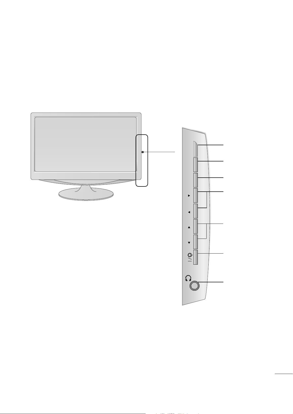
FRONT PANEL CONTROLS
■
This is a simplified representation of the front panel. The image shown may be somewhat different from your
set.
CHANNEL
Buttons
VOLUME
Buttons
MENU
Button
ENTER
Button
INPUT
Button
Power
Button
Headphone
Jack
INPUT
MENU
VOL CHENTER
<<MM222277WWAA >> <<MM223377WWAA >>
2
PREPARATION
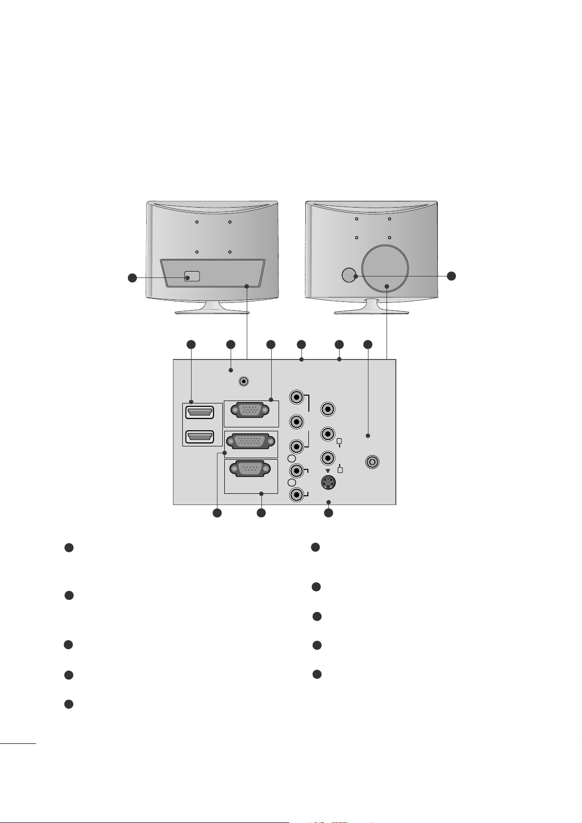
BACK PANEL INFORMATION
■
This is a simplified representation of the back panel. The image shown may be somewhat different from your
set.
2
1
1
9 10
8
4 6 73 5
PPoo wwee rr CCoorr dd SSoocckkee tt
This set operates on AC power. The voltage is indicated on the Specifications page. Never attempt to
operate the set on DC power.
HHDD MM II II nn ppuu tt
Connect a HDMI signal to HDMI IN.
Or DVI (VIDEO) signal to HDMI IN with DVI to
HDMI cable.
RRGG BB// DDVV II AAuuddiioo IInnpp uu tt
Connect the audio from a PC.
RRGG BB IInnpp uutt ((PP CC))
Connect the output from a PC.
CC oo mmpp oonneenntt IInnppuutt
Connect a component video/audio device to these
jacks.
AAVV((AAuuddiioo // VVii ddee oo )) IInnppuutt
Connect audio/video output from an external
device to these jacks.
AAnnttee nn nn aa IInnpp uu tt
Connect over-the-air signals to this jack.
DDVV II--DD IInnppuutt ((PP CC))
Connect the output from a PC.
RRSS--223322CC IINN ((CCOO NN TTRROOLL && SSEE RR VVIICCEE )) PPOO RR TT
Connect to the RS-232C port on a PC.
SS--VV ii ddeeoo IInnpp uutt
Connect S-Video out from an S-VIDEO device.
1
2
3
4
5
6
7
8
9
10
AUDIO IN
(RGB/DVI)
1
RGB IN (PC)
2
DVI-D IN (PC)
RS-232C IN
(CONTROL & SERVICE)
HDMI IN
COMPONENTINAV IN
Y
P
B
VIDEO
P
R
L
AUDIO
R
S-VIDEO
VIDEO AUDIO
(MONO)
L
ANTENNA/
CABLE IN
R
3
PREPARATION
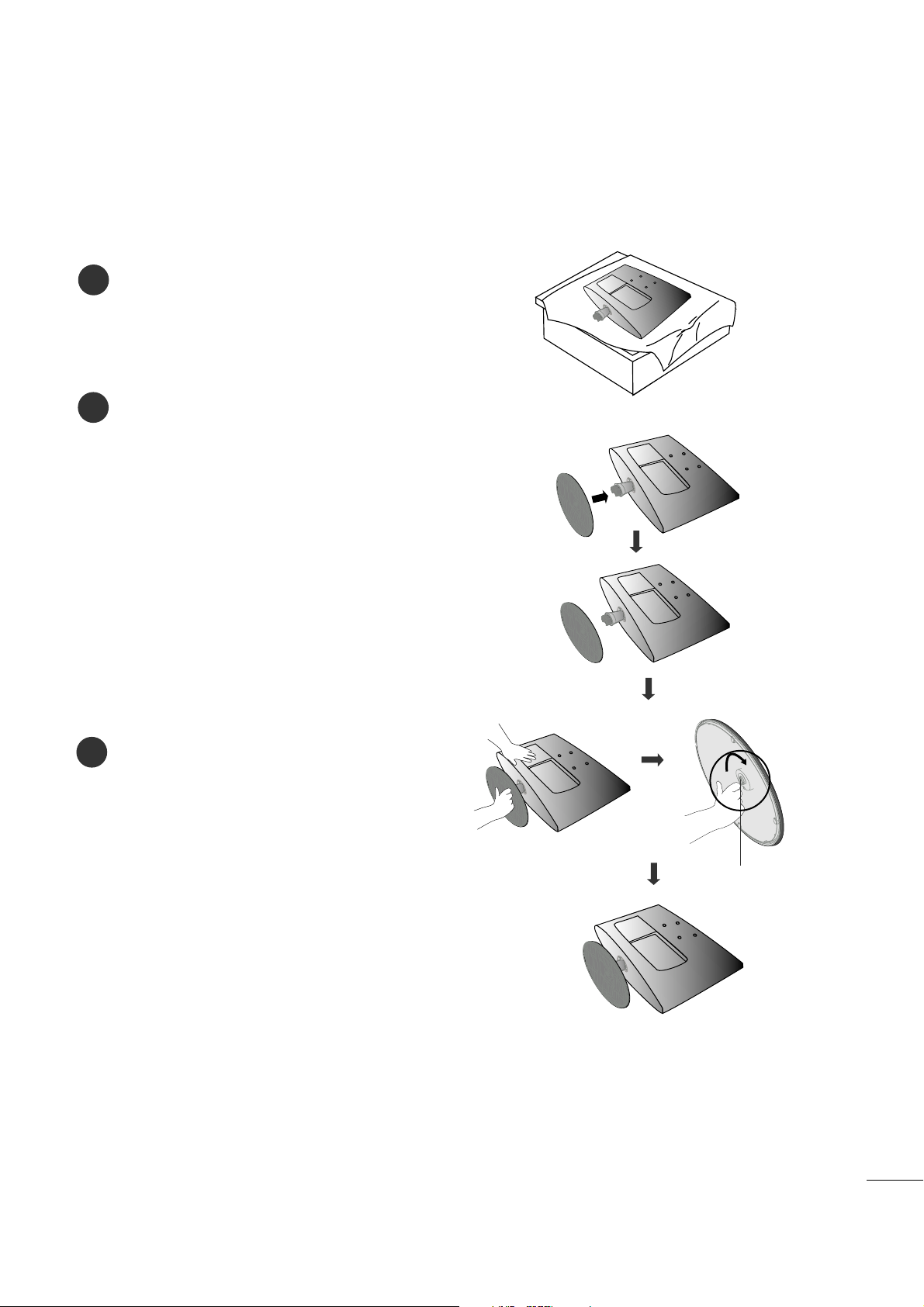
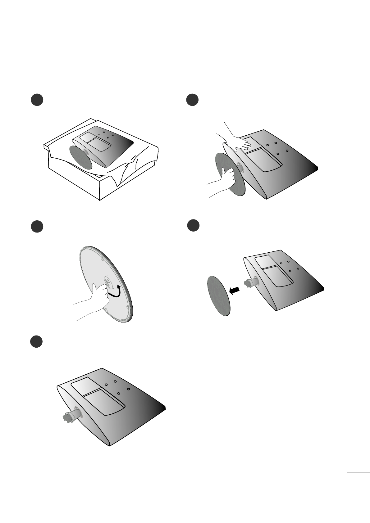
STAND INSTALLATION
■
The image shown may be somewhat different from your set.
1
2
3
Carefully place the product screen side down on a
cushioned surface that will protect product and
screen from damage.
Insert the
ss ttaanndd bbaa ss ee
into the product
Attach the monitor to the Stand Base by turning
the screw to the right.
* Turn the screw by using the screw handle
Screw
<M227WA>
4
PREPARATION
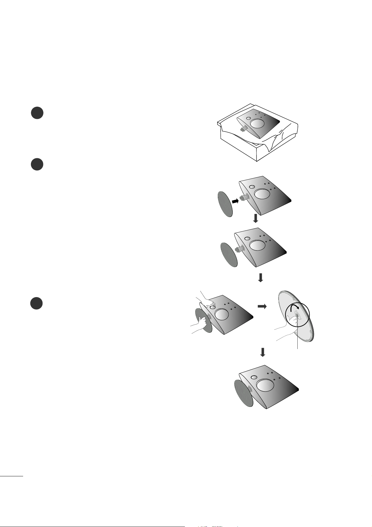
STAND INSTALLATION
■
The image shown may be somewhat different from your set.
1
2
3
Carefully place the product screen side down on a
cushioned surface that will protect product and
screen from damage.
Insert the
ss ttaanndd bbaa ss ee
into the product
Attach the monitor to the Stand Base by turning
the screw to the right.
* Turn the screw by using the screw handle
Screw
<M237WA>
5
PREPARATION
DETACHING STAND
1
2
3
Place the set screen side down on a cushion or
soft cloth.
Detach the monitor to the Stand Base by turning the screw to the left.
Turn the screw by using the screw handle
4
Pull the stand base.
5
■
The image shown may be somewhat different from your set.
<M227WA>

6
PREPARATION
DETACHING STAND
1
2
3
Place the set screen side down on a cushion or
soft cloth.
Detach the monitor to the Stand Base by turning the screw to the left.
Turn the screw by using the screw handle
4
Pull the stand base.
5
■
The image shown may be somewhat different from your set.
<M237WA>
7
PREPARATION
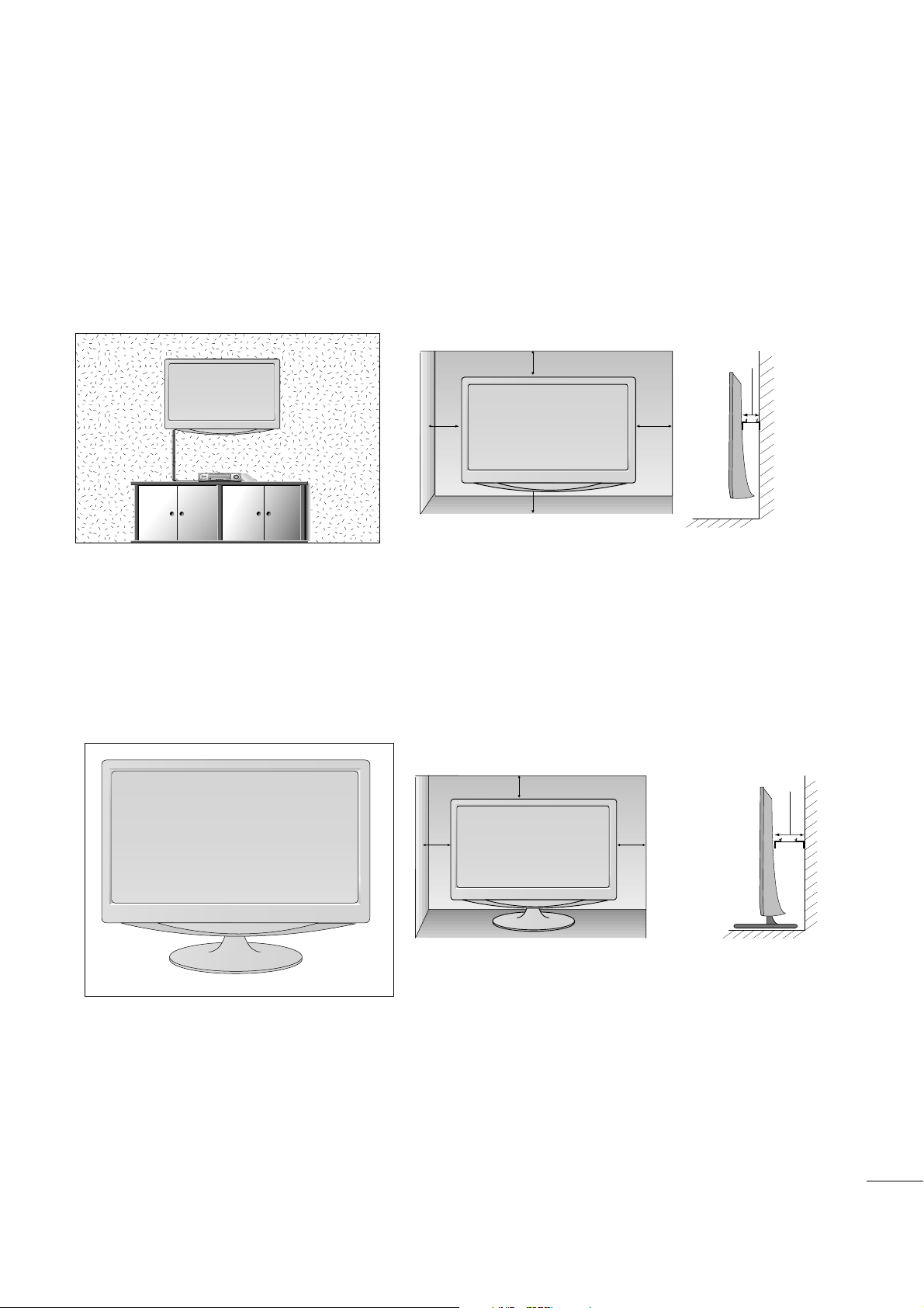
DESKTOP PEDESTAL INSTALLATION
For proper ventilation, allow a clearance of 4 inches on each side and from the wall.
4 inches
4 inches
4 inches
4 inches
WALL MOUNT: HORIZONTAL INSTALLATION
For proper ventilation, allow a clearance of 4 inches on each side and from the wall. Detailed installation
instructions are available from your dealer, see the optional Tilt Wall Mounting Bracket Installation and
Setup Guide.
4 inches
4 inches
4 inches 4 inches
4 inches
8
PREPARATION
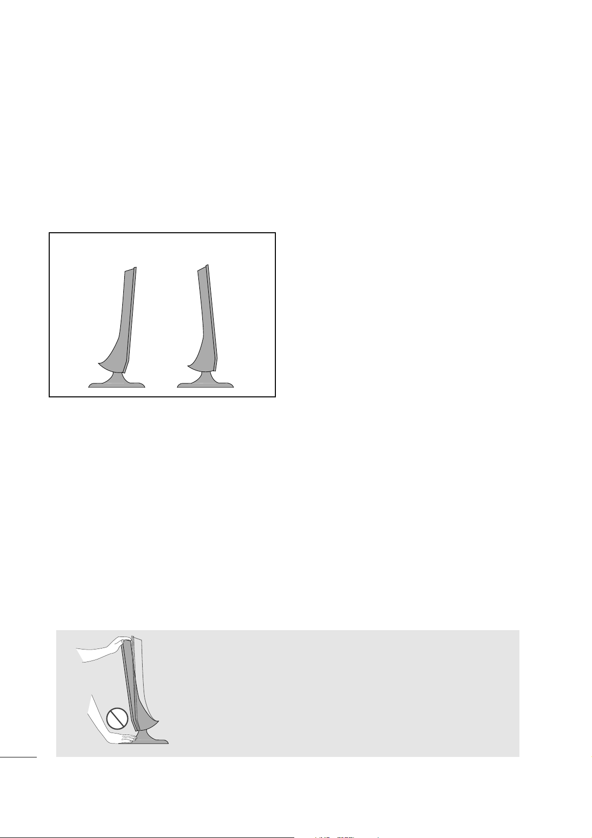
POSITIONING YOUR DISPLAY
■
The image shown may be somewhat different from your set.
Adjust the position of the panel in various ways for maximum comfort.
•• TT iilltt rr aa nn ggee
LOCATION
Position your set so that no bright light or sunlight falls directly onto the screen. Care should be taken not to
expose the set to any unnecessary vibration, moisture, dust or heat. Also, ensure that the set is placed in a position to allow a free flow of air. Do not cover the ventilation openings on the back cover.
If you intend to mount the set to a wall, attach Wall mounting interface (optional parts) to the back of the set.
When you install the set using the wall mounting interface (optional parts), attach it carefully so it will not drop.
- Be sure to use screws and a wall mount that meet VESA standards.
- Using screws longer than those recommended might damage the product.
- Using screws that do not meet VESA standards might either damage the product or result in it coming away from
the wall. We will not be held responsible for any damage resulting from failure to follow these instructions.
< Screw Mounting Interface Dimension >
M227WA : 100mm x 100mm hole spacing
M237WA : 75mm x 75mm hole spacing
-6°~ -2
°
12°~ 18
°
WW aarr nn iinngg ::
When adjusting the angle of the screen,do not put your
finger(s)in between the head of the monitor and the stand
body.You can hurt your finger(s).
9
PREPARATION
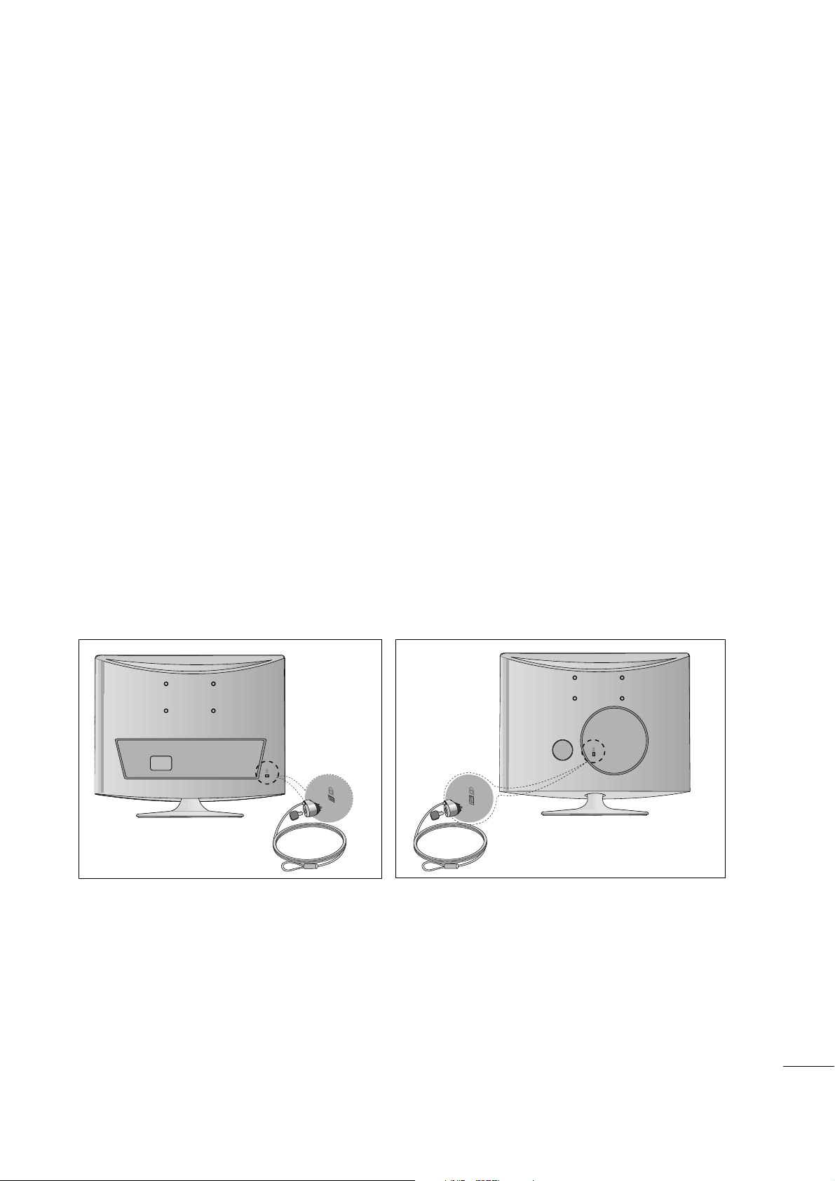
KENSINGTON SECURITY SYSTEM
- The product is equipped with a Kensington Security System connector on the back panel. Connect the
Kensington Security System cable as shown below.
- For detailed installation and use of the Kensington Security System, refer to the user’s guide provided with
the Kensington Security System.
For further information, contact
hhttttpp:: // // wwwwww..kkee nn ss ii nn ggttoonn.. ccoo mm
, the internet homepage of the
Kensington company. Kensington sells security systems for expensive electronic equipment such as notebook PCs and LCD projectors.
NOTE
- The Kensington Security System is an optional accessory.
NOTES
a. If the product feels cold to the touch, there may be a small “flicker” when it is turned on.
This is normal, there is nothing wrong with product.
b. Some minute dot defects may be visible on the screen, appearing as tiny red, green, or blue spots.
However, they have no adverse effect on the monitor's performance.
c. Avoid touching the LCD screen or holding your finger(s) against it for long periods of time.
Doing so may produce some temporary distortion effects on the screen.
<M227WA> <M237WA>
10
EXTERNAL EQUIPMENT SETUP
■
For optimum picture quality, adjust antenna direction.
■
An antenna cable and converter are not supplied.
■
To prevent equipment damage, never plug in any power cords until you have finished connecting all equipment.
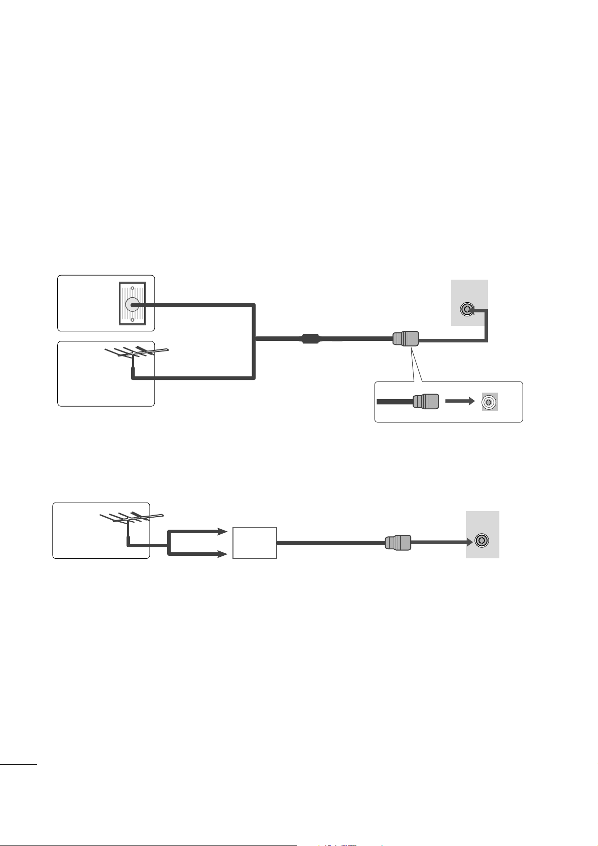
Multi-family Dwellings/Apartments
(Connect to wall antenna socket)
Single-family Dwellings /Houses
(Connect to wall jack for outdoor antenna)
Outdoor
Antenna
(VHF, UHF)
Wall
Antenna
Socket
RF Coaxial Wire (75 ohm)
ANTENNA CONNECTION
Antenna
UHF
VHF
■
In poor signal areas, to get better picture quality, install a signal amplifier to the antenna as shown above.
■
If signal needs to be split for two sets, use an antenna signal splitter for connection.
ANTENNA/
CABLE IN
AV 1
AV 1
ANTENNA/
CABLE IN
AV 1
AV 1
Signal
Amplifier
11
EXTERNAL EQUIPMENT SETUP
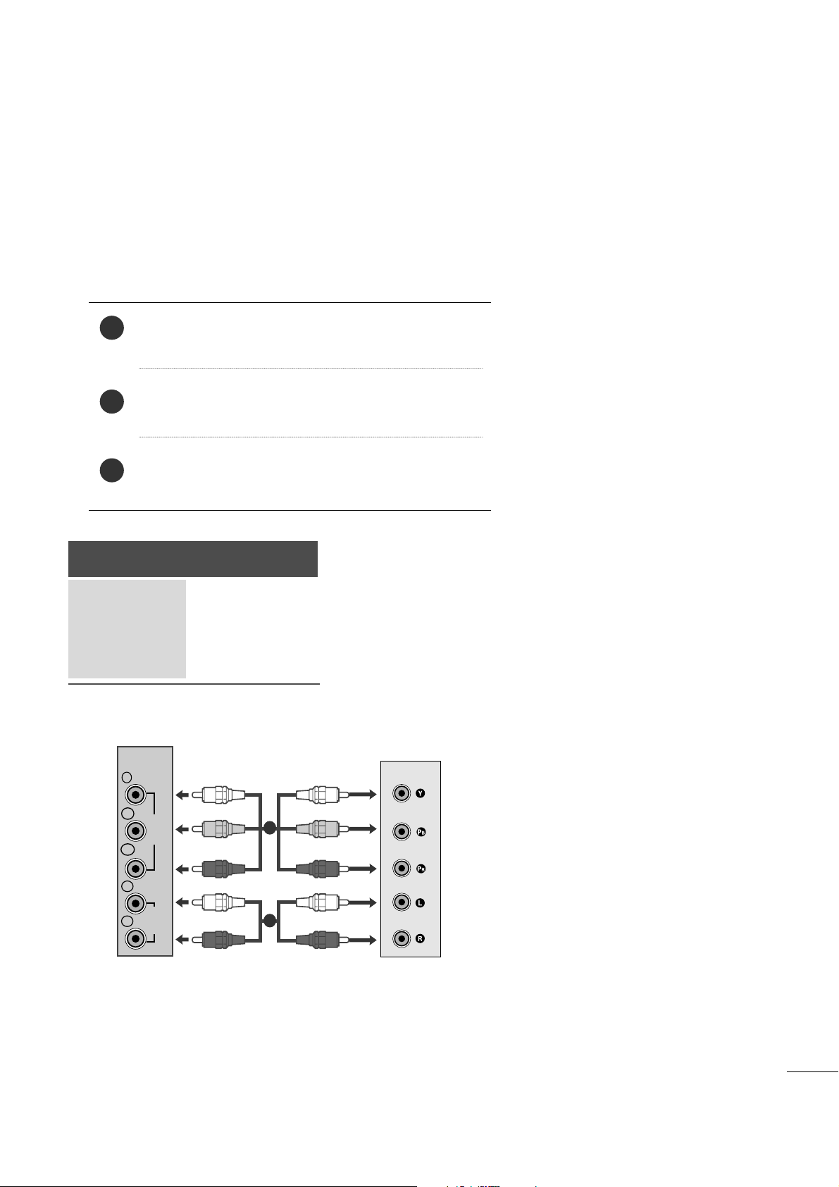
Connect the SET-TOP outputs to the
CCOOMMPPOONNEENNTT II NN
VVIIDDEEOO
sockets (Y P
B PR) on the set.
Connect the audio cable from the SET-TOP to
CCOOMMPP OO--
NNEE NNTT IINN AAUUDDIIOO
sockets of the set.
Press the
II NNPP UU TT
button to select
CCoommppoonneenn tt..
2
3
1
HD RECEIVER SETUP
■
To prevent the equipment damage, never plug in any power cords until you have finished connecting all equipment.
■
The image shown may be somewhat different from your set.
When connecting with a component cable
Signal
480i/576i
480p/576p
720p/1080i
1080p
Component
Yes
Yes
Yes
Yes
VIDEO
COMPONENT
IN
AUDIO
Y
P
B
P
R
L
R
1
2
12
EXTERNAL EQUIPMENT SETUP
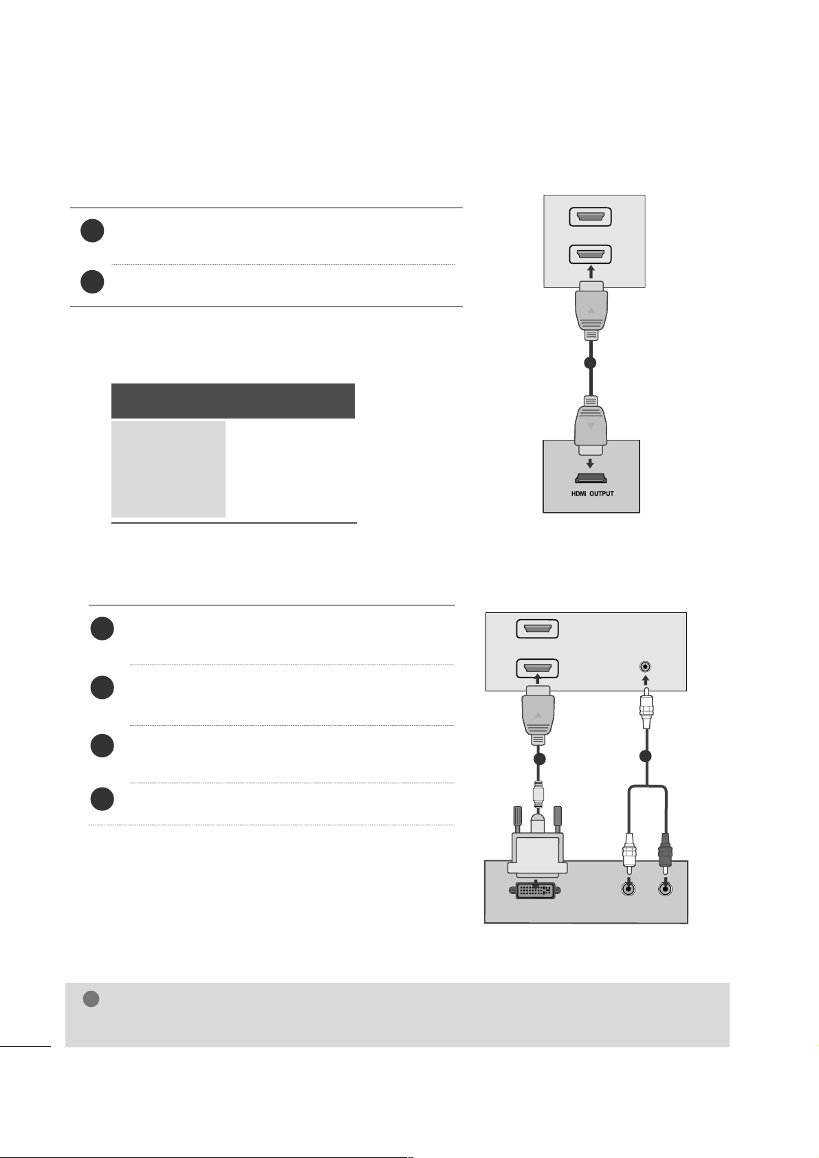
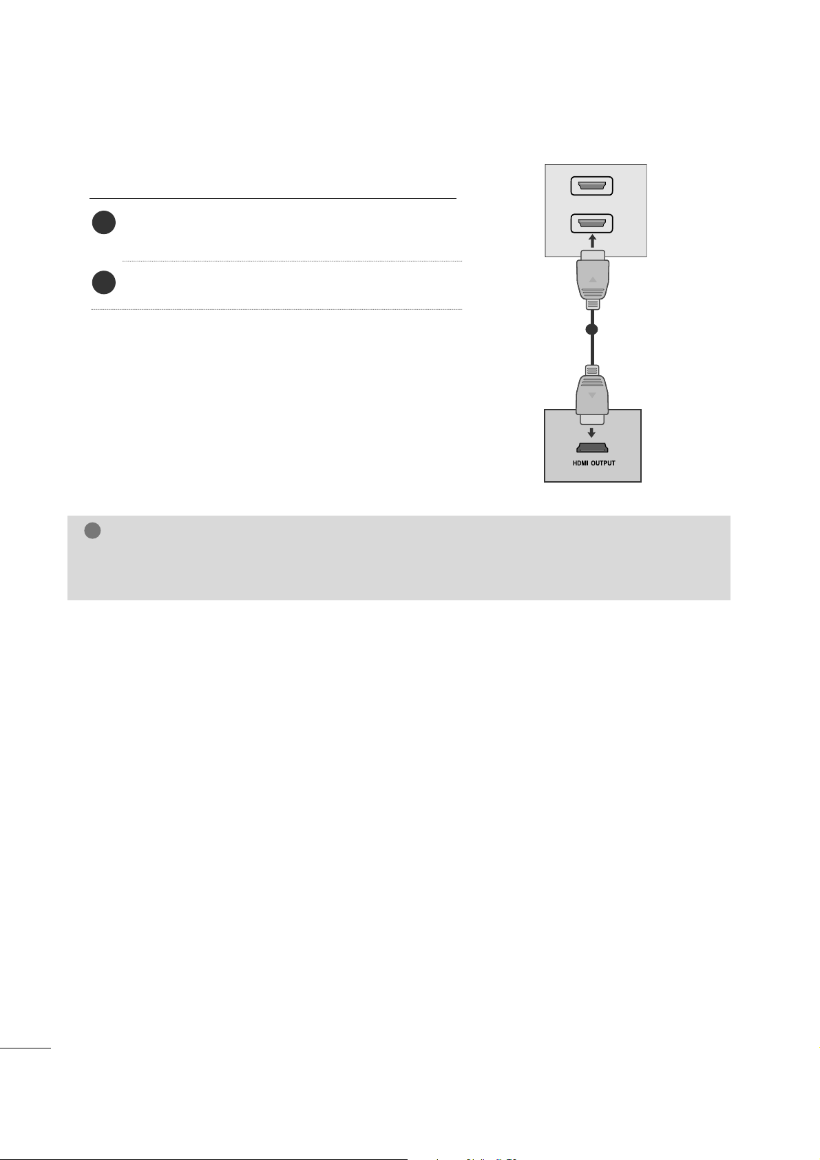
When connecting with a HDMI
Connect the HDMI output of the digital set-top box to the
HHDDMM II IINN
jack on the set.
1
Press the INPUT button to select HDMI1 or HDMI2.
2
Connect the digital set-top box to
HHDDMM II IINN
jack on
the set.
Connect the audio output of the digital set-top box to
the
AAUUDDIIOO IINN ((RRGGBB//DD VVII))
jack on the set.
Turn on the digital set-top box. (Refer to the owner’s
manual for the digital set-top box.
)
Press the INPUT button to select HDMI1 or HDMI2.
2
3
4
1
When connecting with a HDMI to DVI cable
HDMI IN
1
2
1
DVI OUTPUT
AUDIO
R
L
A
U
D
IO
IN
(R
G
B
/D
VI)
HDMI IN
1
2
1
2
NOTE
!
GG
HDMI Input does not support PC mode. If it is connected PC, the screen may not be displayed properly.
Signal
480i/576i
480p/576p
720p/1080i
1080p
HDMI
No
Yes
Yes
Yes
13
EXTERNAL EQUIPMENT SETUP
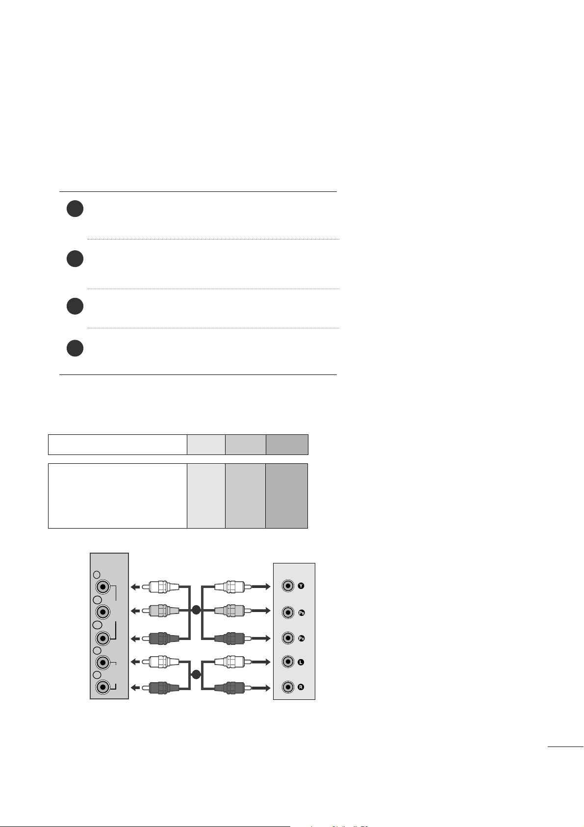
DVD SETUP
When connecting with a component cable
Component Input ports
To get better picture quality, connect a DVD player to the component input ports as shown below.
Component ports on the set
YPBP
R
Video output ports
on DVD player
Y
Y
Y
Y
PB
B-Y
Cb
Pb
P
R
R-Y
Cr
Pr
Connect the video output sockets (Y P
B PR) of the DVD to
the
CCOOMMPPOO NNEENNTT II NN VVII DDEEOO
sockets (Y P
B PR) of the set.
Connect the audio cable from the DVD to
CCOOMMPPOO NNEE NNTT
II NN AAUU DDII OO
sockets of the set.
Press the
II NNPP UU TT
button to select
Component.
Press the
PPLL AAYY
button on the DVD.
The DVD playback picture appears on the screen.
2
3
4
1
VIDEO
COMPONENT
IN
AUDIO
Y
P
B
P
R
L
R
1
2
14
EXTERNAL EQUIPMENT SETUP
When connecting HDMI cable
Connect the HDMI output of the DVD to the
HHDDMM II IINN
jack on the set.
Press the INPUT button to select HDMI1 or HDMI2.
1
2
GG
Set can receive the video and audio signal simultaneously by using a HDMI cable.
GG
If the DVD player does not support Auto HDMI, you need to set the DVD output resolution appropriately.
NOTE
!
HDMI IN
1
2
1
15
EXTERNAL EQUIPMENT SETUP
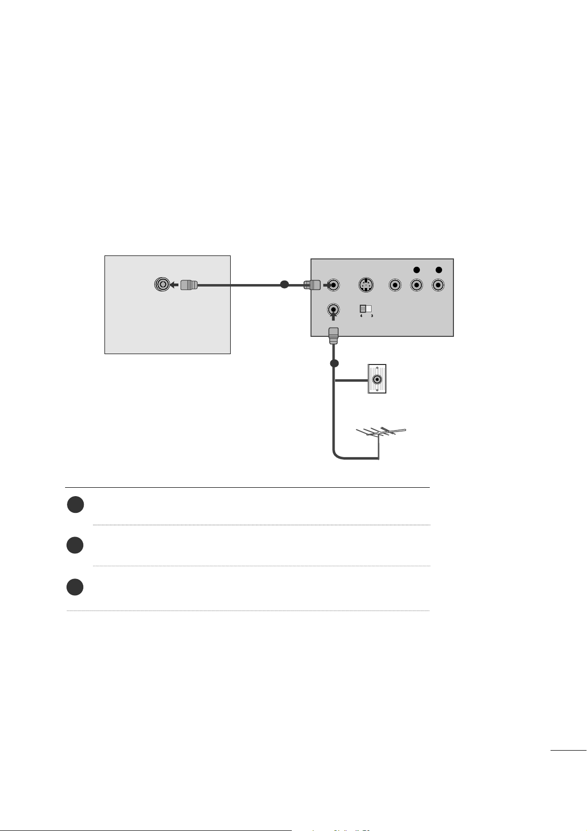
VCR SETUP
■
To avoid picture noise (interference), leave an adequate distance between the VCR and set.
■
Typically a still picture is shown on the VCR. If a user uses 4:3 picture format for a long time, an afterimage
may remain on the sides of the screen.
OUTPUT
SWITCH
ANT IN
R
S-VIDEO VIDEO
ANT OUT
L
ANTENNA IN/
CABLE IN
Wall Jack
Antenna
1
2
When connecting with an antenna
Connect the ANT OUT socket of the VCR to the ANTENNA IN socket of the set.
Connect the antenna cable to the RF ANT IN in socket of the VCR.
Press the
PPLL AAYY
button on the VCR and match the appropriate program between
the set and VCR for viewing..
1
2
3
16
EXTERNAL EQUIPMENT SETUP
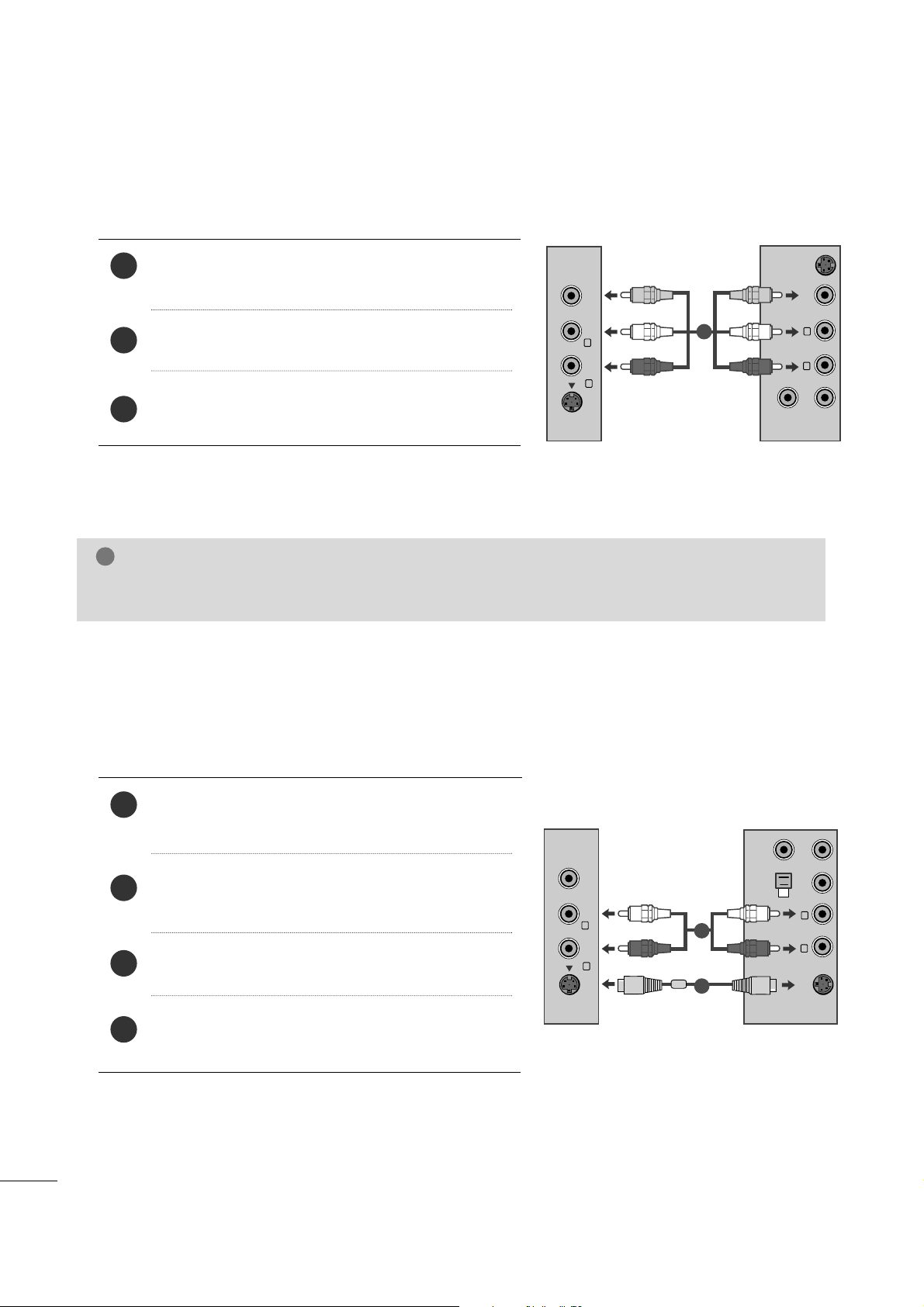
When connecting with a RCA cable
Connect the audio/video out sockets of the VCR to
AUDIO/VIDEO in sockets of the set.
Press the INPUT button to select AV.
Press the PLAY button on the VCR.
The VCR playback picture appears on the screen.
2
3
1
When connecting with an S-Video cable
Connect the S-Video socket of the VCR to the SVIDEO socket of the set.
Connect the audio cable from the S-VIDEO VCR to the
AUDIO sockets of the set.
Press the INPUT button to select AV.
Press the PLAY button on the VCR.
The VCR playback picture appears on the screen.
2
3
4
1
NOTE
!
GG
If you have a mono VCR, connect the audio cable from the VCR to the AUDIO L/MONO jack of the set.
VIDEO ANT IN
ANT OUT
S-VIDEO
L
R
VIDEO AUDIO
(MONO)
S-VIDEO
L
R
AV IN
1
VIDEO AUDIO
(MONO)
S-VIDEO
L
R
AV IN
VIDEOANT IN
ANT OUT
OUTPUT
SWITCH
34
S-VIDEO
L
R
1
2
17
EXTERNAL EQUIPMENT SETUP
PC SETUP
This product provides Plug and Play capability, meaning that the PC adjusts automatically to the set's settings.
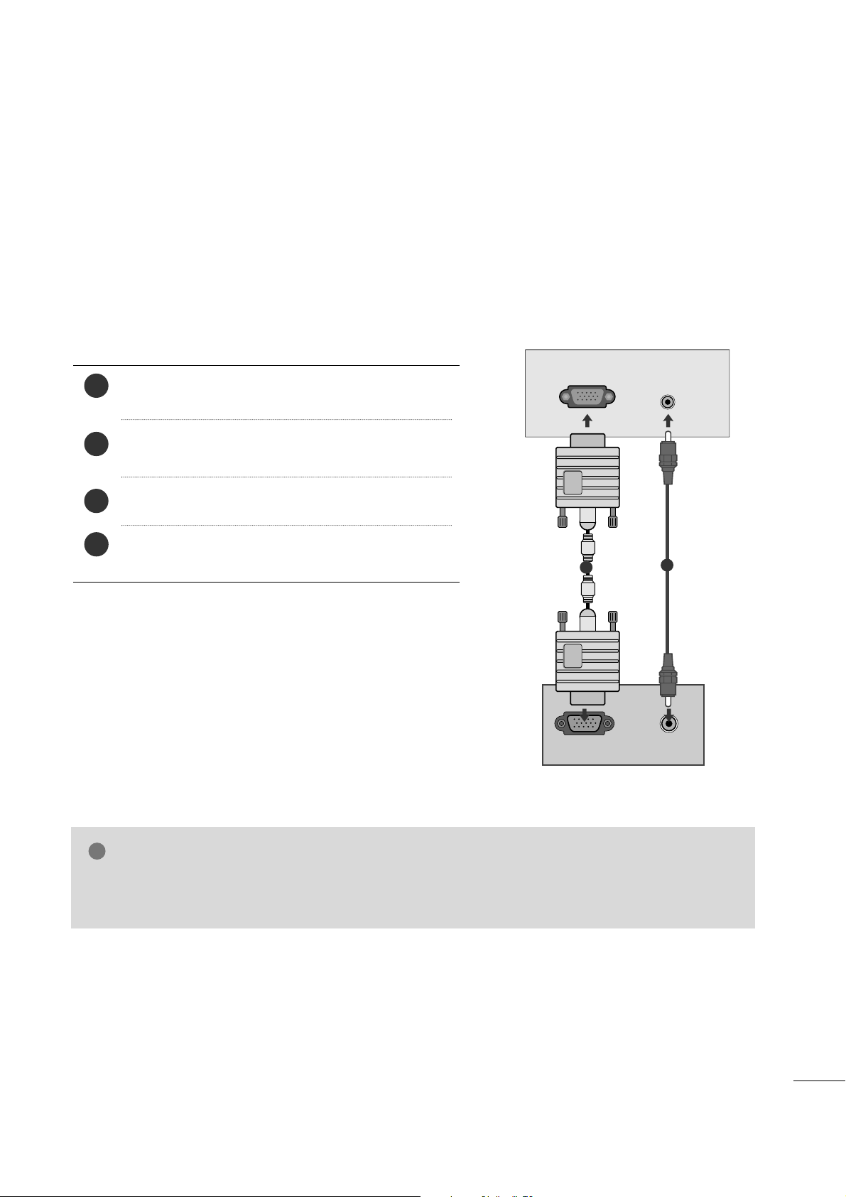
When connecting with a D-sub 15 pin cable
4
Connect the signal cable from the RGB output socket of the
PERSONAL COMPUTER to the RGB IN(PC) jack of the set.
Connect the audio cable from the PC to the
AAUUDDIIOO IINN
((RRGGBB//DD VVII))
jack of the set.
Press the INPUT button to select RGB PC.
Switch on the PC, and the PC screen appears on the set.
The set can be operated as a PC monitor.
2
3
1
RGB OUTPUT
AUDIO
AUDIO IN
(RGB/DVI)
RGB IN (PC)
1
2
NOTE
!
GG
You must use shielded signal interface cables (D sub 15 pin cable, DVI cable) with ferrite cores to maintain
standard compliance for the product.
18
EXTERNAL EQUIPMENT SETUP
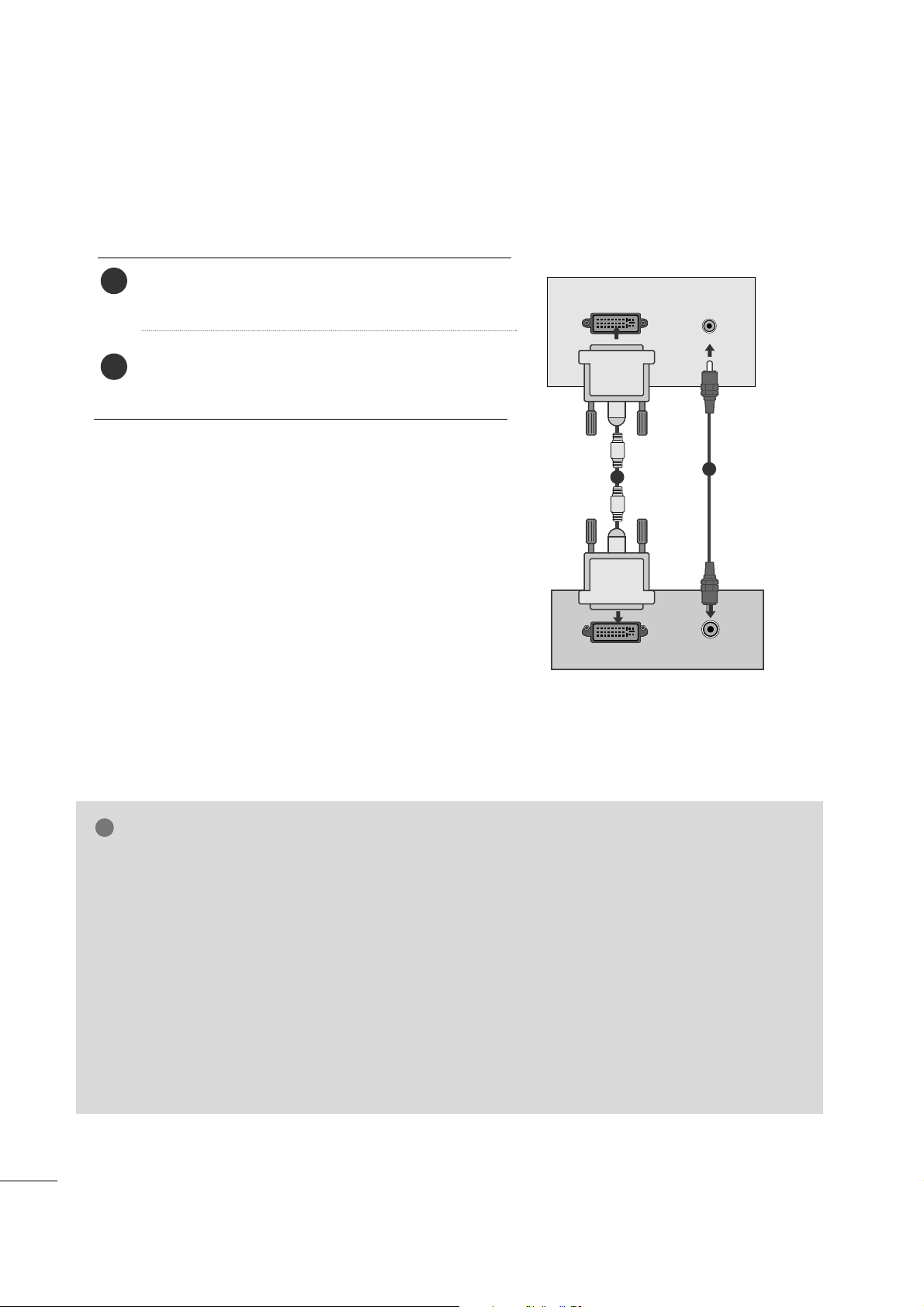
When connecting with a DVI cable
Connect the DVI output of the PC to the
DDVVII --DD IINN
jack on the set.
Connect the audio cable from the PC to the
AAUUDDII OO
II NN ((RRGGBB//DD VVII))
jack of the set.
2
1
NOTE
!
GG
If the set is cold, there may be a small “flicker”
when the set is switched on. This is normal, there
is nothing wrong with the set.
GG
If possible, use the 1920x1080@60Hz video
mode to obtain the best image quality for your
LCD monitor. If used with other resolutions, some
scaled or processed pictures may appear on the
screen. The set has been preadjusted to the mode
1920x1080@60Hz.
GG
Some dot defects may appear on the screen, like
Red, Green or Blue spots. However, this will have
no impact or effect on the monitor performance.
GG
Do not press the LCD screen with your finger for
a long time as this may produce some temporary
distortion effects on the screen.
GG
Avoid keeping a fixed image on the set’s screen
for prolonged periods of time. The fixed image
may become permanently imprinted on the
screen; use a screen saver when possible.
AUDIO
DVI OUTPUT
AUDIO IN
(RGB/DVI)
DVI-D
IN (PC)
1
2
 Loading...