

LG M2762D-PC, M2362D-PC, M2362D-PZ, M2362D, M2262D-PC Owner's Manual
...
ENGLISH
OWNER’S MANUAL
MONITOR TV
Please read this manual carefully before operating
your set and retain it for future reference.
MONITOR TV MODELS
M1962D
M2062D
M2262D
M2362D
M2762D
www.lge.com

1
PREPARATION
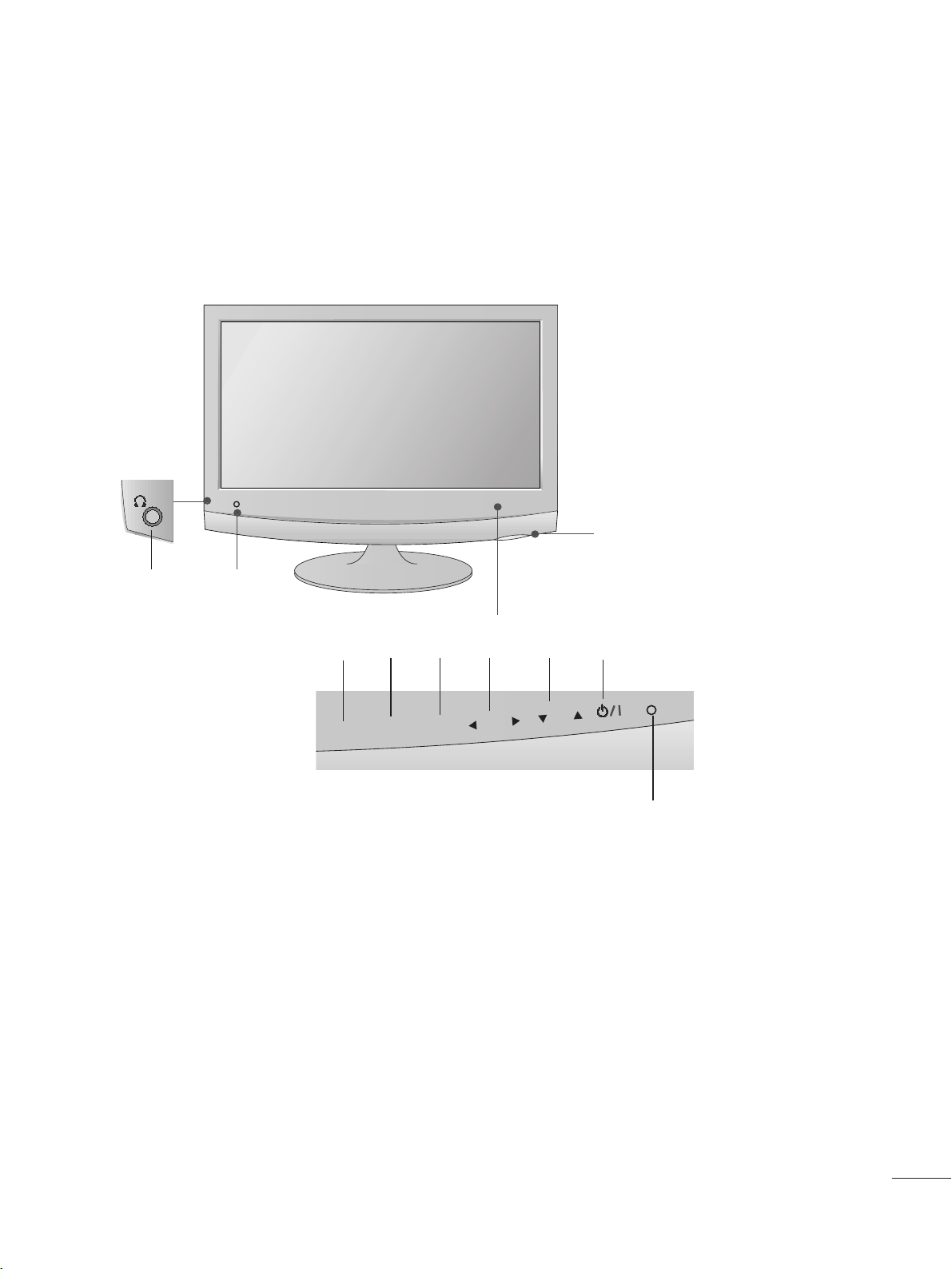
FRONT PANEL CONTROLS
■
This is a simplified representation of the front panel. The image shown may be somewhat different from your set.
INPUT
Button
INPUT
MENU
PR
VOL
OK
MENU
Button
OK
Button
VOLUME
Buttons
PROGRAMME
Buttons
Powe r
Button
Headphone
Jack
IR receiver
(Remote controller
receiver)
LLiigghhtt SSeennssoorr
This is lens for light sensor
select outside luminance,
when setting AUTO
BRIGHT ON.
PPoowweerr IInnddiiccaattoorr
illuminates blue when the
set is switched on.
Note:You can adjust Power
indicator in the OPTION
menu.
22
PREPARATION
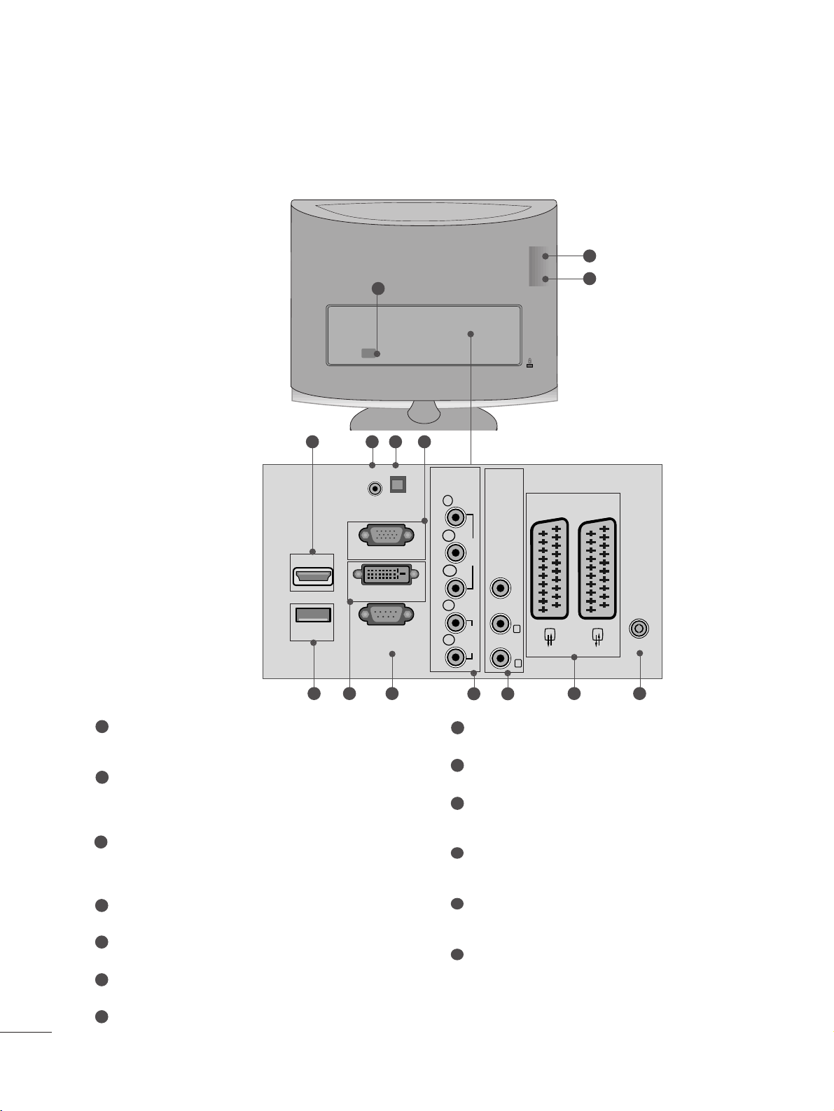
BACK PANEL INFORMATION
PPCCMMCC IIAA (( PPeerrss oonn aall CCoommppuu tt eerr MMeemm oorryy CCaa rrdd
IInn tteerrnnaa tt iioonn aall AA ssssoocciiaa ttiioonn )) CCaarrdd SSlloott
This feature is not available in all countries.
PPoowweerr CCoorrdd SSoocckk eett
This set operates on AC power. The voltage is indicated
on the Specifications page. Never attempt to operate the
set on DC power.
HHDDMMII IInnppuutt ((NNoott SS uuppppoorrtt PPCC))
Connect a HDMI signal to HDMI IN.
Or DVI (VIDEO) signal to HDMI IN with DVI to HDMI
cable.
RR GG BB //DDVVII AAuu dd iioo II nnppuutt
Connect the audio from a PC.
OOppttiiccaall DDiiggiittaall AAuuddii oo OOuu tt
Connect digital audio from various types of eguipment
RR GGBB II NN PP UUTT ((PP CC ))
Connect the output from a PC.
UUSS BB IINN
DDVVII-- DD IInnppuu tt
Connect the output from a PC.
RR SS--22 3322 CC IINN ((CCOO NNTTRROO LL && SSEERRVVIICCEE)) PPOORRTT
Connect to the RS-232C port on a PC.
CC oo mmppoonneenn tt II nnppuutt
Connect a component video/audio device to these
jacks.
AA uuddiioo// VViiddee oo II nnppuutt
Connect audio/video output from an external device to
these jacks.
EEuu rroo SSccaarr tt SS oocc kkee tt (( AAVV11 // AAVV 22))
Connect scart socket input or output from an external
device to these jacks.
AA nntteennnn aa II nnppuutt
Connect over-the-air signals to this jack.
1
2
3
4
5
6
7
8
9
10
11
12
13
■
This is a simplified representation of the back panel. The image shown may be somewhat different from your set.
V 1
V 2
3
9
10 11
2
1
3
87 1312
64 5
AUDIO IN
(RGB/DVI)
HDMI IN 1
USB IN
RGB IN (PC)
DVI-D IN (PC)
RS-232C IN
(CONTROL & SERVICE)
OPTICAL
DIGITAL
AUDIO OUT
COMPONENTINAV IN 3
Y
P
B
VIDEO
P
R
L
AUDIO
R
VIDEO -AUDIO-
(MONO)
L
R
AV 1
AV 2
ANTENNA/
CABLE IN
33
PREPARATION
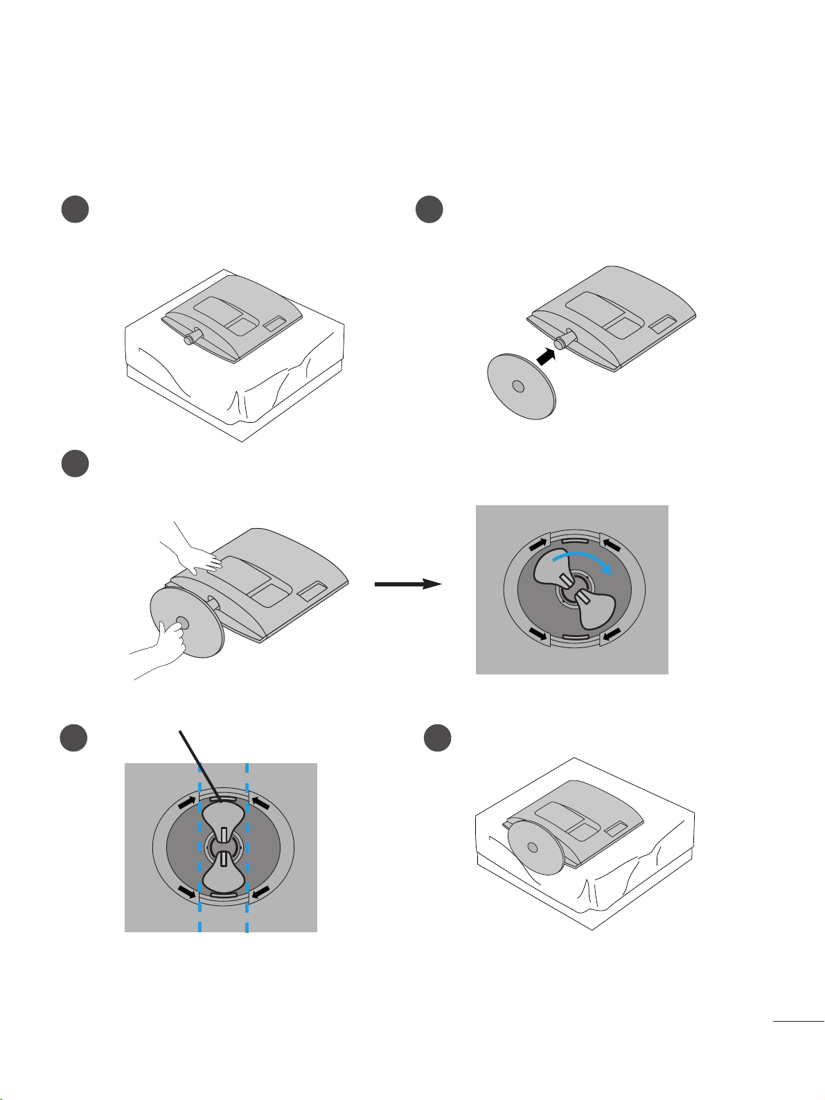
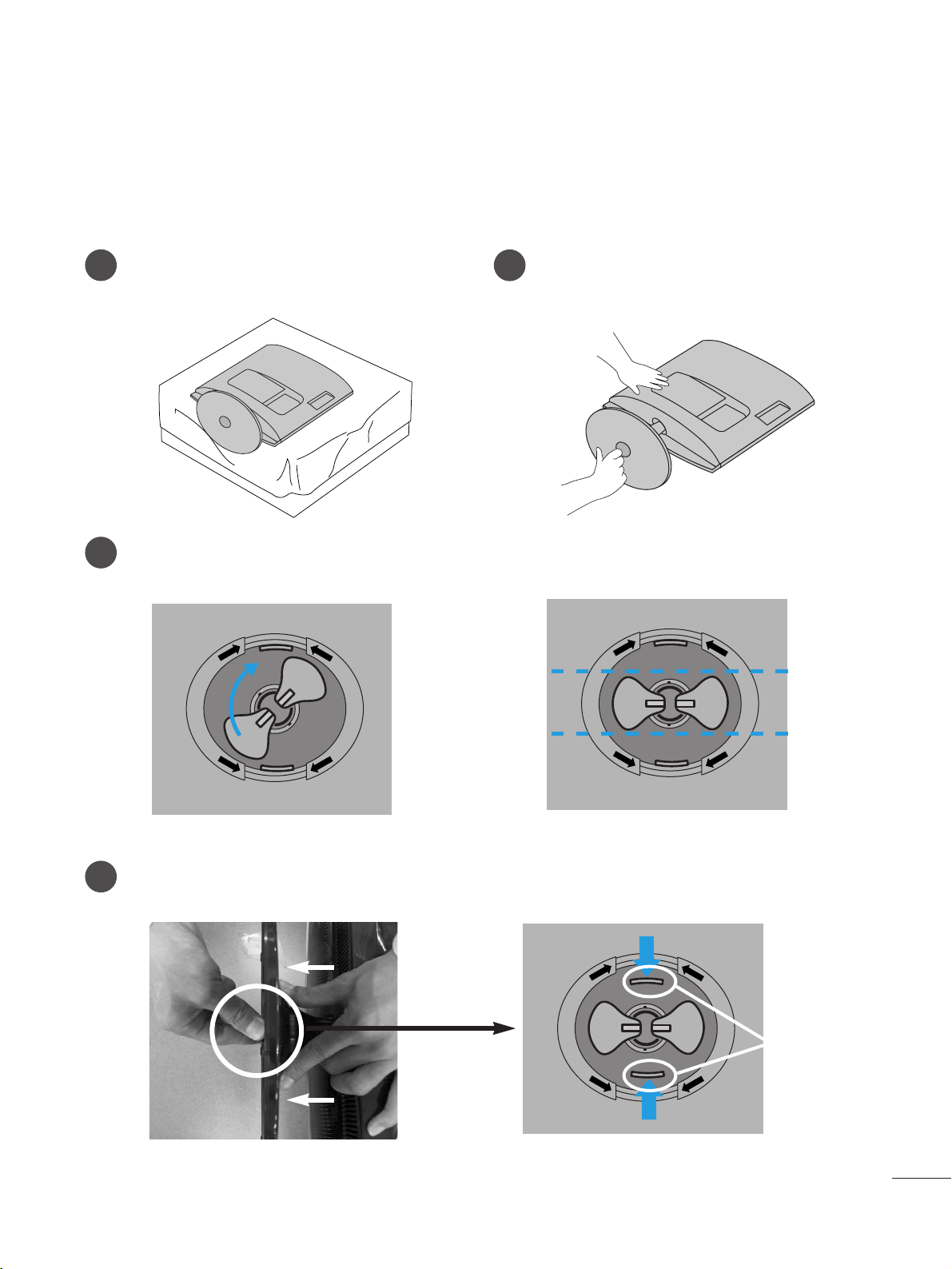
STAND INSTALLATION
■
The image shown may be somewhat different from your set.
1
2
3
Carefully place the product screen side down on a
cushioned surface that will protect product and
screen from damage.
Insert the
ssttaanndd bbaassee
into the product
<<MM11996622 DD//MM22006622DD//MM22 22 6622DD// MM2233 6622DD>>
Turn the Stand Base Lock through 90
°
to fix the Stand Base to the Stand Body.
BB aa ssee LLoocckk
<<LLoocc kk eedd>>
4 5
O
P
E
N
O
P
E
N
O
P
E
N
O
P
E
N
44
PREPARATION
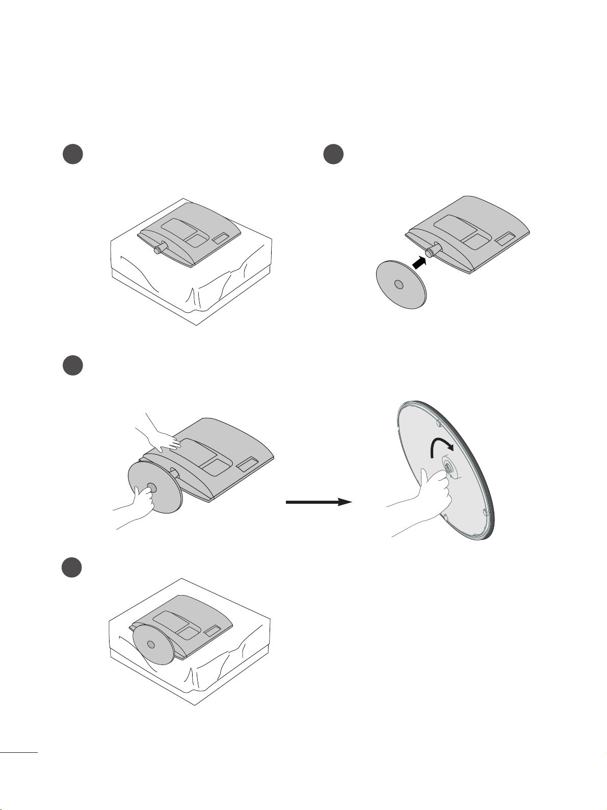
<<MM22776622DD>>
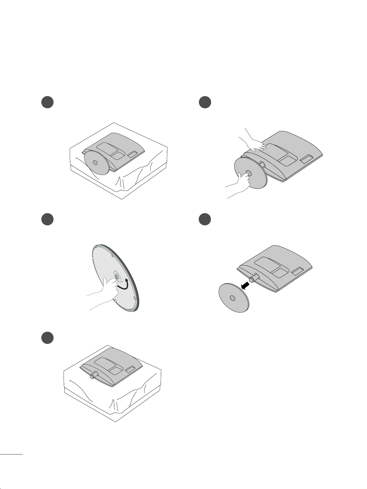
STAND INSTALLATION
■
The image shown may be somewhat different from your set.
1
2
3
Carefully place the product screen side down on a
cushioned surface that will protect product and
screen from damage.
Insert the
ssttaanndd bbaassee
into the product
Attach the monitor to the Stand Base by turning the screw to the right.
*Turn the screw by using the screw handle
4
55
PREPARATION
DETACHING STAND
1
2
3
4
Place the set screen side down on a cushion or
soft cloth.
Detach the monitor to the Stand Base by turning
the screw to the left.
Turn the Stand Base Lock through 90
° to separate the Stand Base from the Stand Body.
Pushing Latch inside, Take the stand base from stand body.
O
P
E
N
O
P
E
N
O
P
E
N
O
P
E
N
O
P
E
N
O
P
E
N
■
The image shown may be somewhat different from your set.
LLaatt cc hh
<<MM11996622 DD//MM22006622DD//MM22 22 6622DD// MM2233 6622DD>>
66
PREPARATION
<<MM22776622DD>>
DETACHING STAND
1
2
3
5
Place the set screen side down on a cushion or
soft cloth.
Detach the monitor to the Stand Base by turning the screw to the left.
Turn the screw by using the screw handle.
4
Pull the stand base.
■
The image shown may be somewhat different from your set.
77
PREPARATION
<<MM22776622DD>>
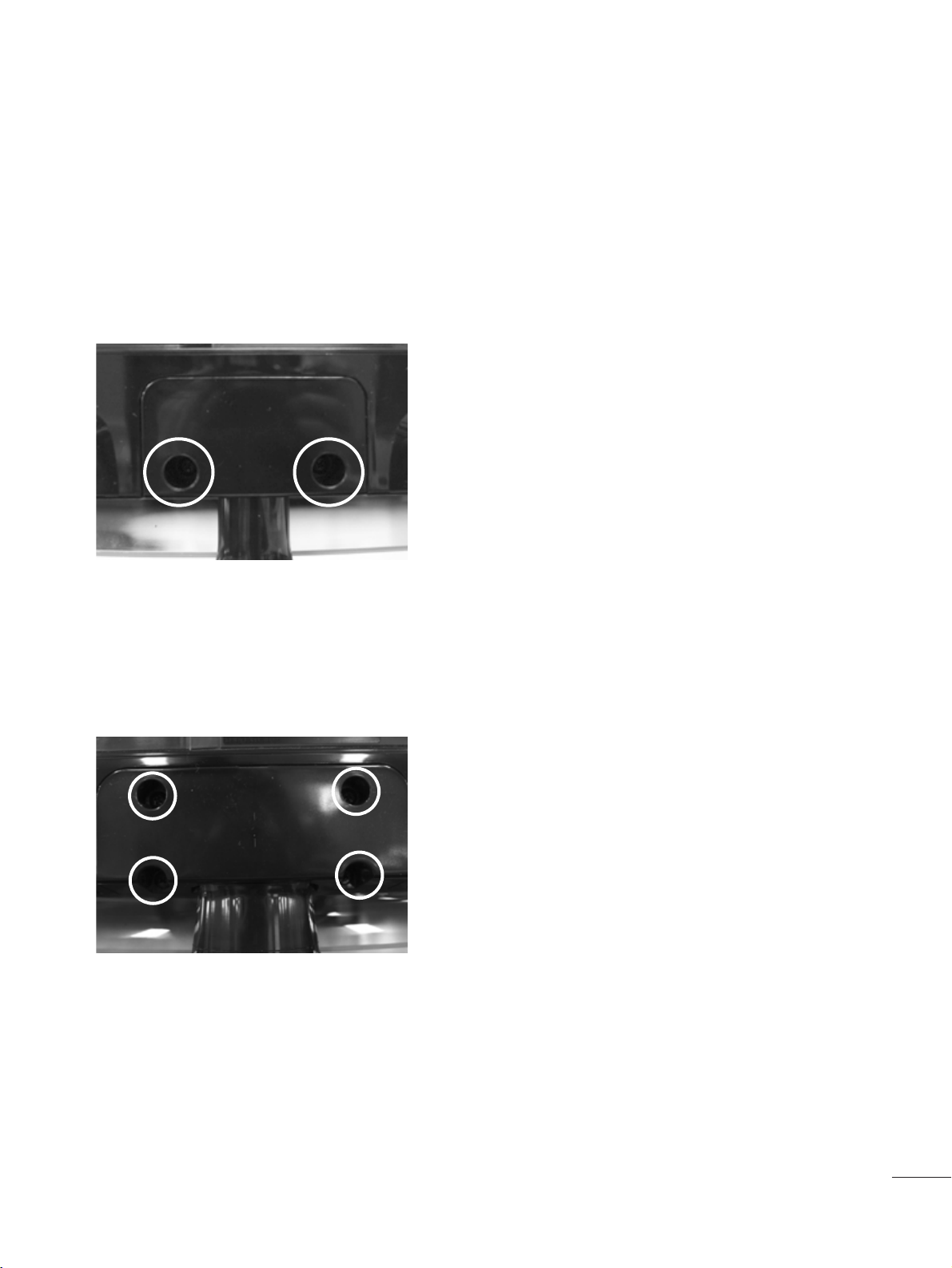
DETACHING STAND BODY
1. Remove the screw 4 point.
2. Pull the stand body.
1. Remove the screw 2 point.
2. Pull the stand body.
■
The image shown may be somewhat different from your set.
■
Remove the Stand Body in the same way as the following when using it as a Wall Hook.
<<MM11996622 DD//MM22006622DD//MM22 22 6622DD// MM2233 6622DD>>

88
PREPARATION
DESKTOP PEDESTAL INSTALLATION
For proper ventilation, allow a clearance of 10 cm on each side and from the wall.
10 c m
10 c m
10 c m
10 c m
WALL MOUNT: HORIZONTAL INSTALLATION
For proper ventilation, allow a clearance of 10 cm on each side and from the wall. Detailed installation instructions
are available from your dealer, see the optional Tilt Wall Mounting Bracket Installation and Setup Guide.
10 c m
10 c m
10 c m 10 c m
10 c m
99
PREPARATION
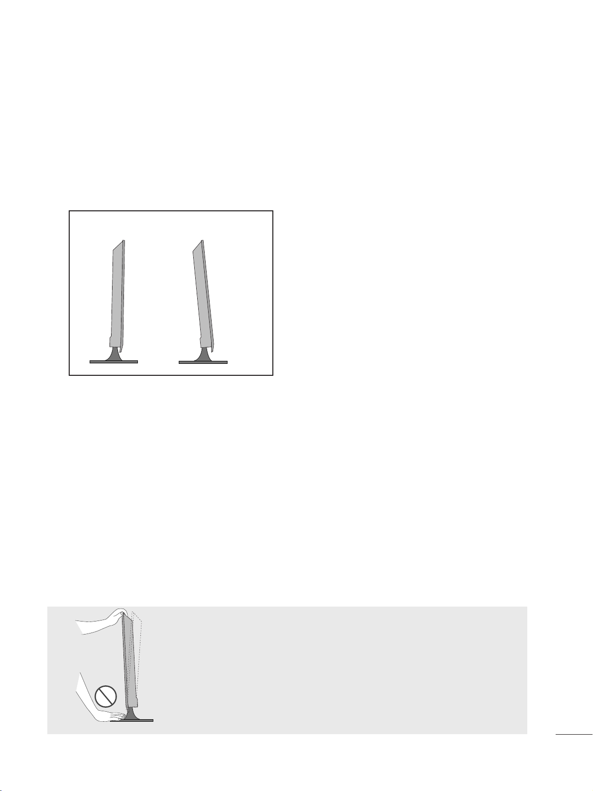
POSITIONING YOUR DISPLAY
■
The image shown may be somewhat different from your set.
Adjust the position of the panel in various ways for maximum comfort.
•• TTiilltt rraann ggee
LOCATION
Position your set so that no bright light or sunlight falls directly onto the screen. Care should be taken not to expose
the set to any unnecessary vibration, moisture, dust or heat. Also, ensure that the set is placed in a position to allow a
free flow of air. Do not cover the ventilation openings on the back cover.
If you intend to mount the set to a wall, attach Wall mounting interface (optional parts) to the back of the set.
When you install the set using the wall mounting interface (optional parts), attach it carefully so it will not drop.
- Be sure to use screws and a wall mount that meet VESA standards.
- Using screws longer than those recommended might damage the product.
- Using screws that do not meet VESA standards might either damage the product or result in it coming away from the
wall. We will not be held responsible for any damage resulting from failure to follow these instructions.
< Screw Mounting Interface Dimension >
MM11 99 66 22 DD//MM220066 22 DD // MM 222266 22 DD // MM 223366 22 DD
: 100 mm x 100 mm hole spacing
MM22 7766 22 DD
: 200 mm x 100 mm hole spacing
-5
°
15
°
WWaarrnniinngg ::
When adjusting the angle of the screen,do not put your finger(s)in
between the head of the monitor and the standbody.You can hurt
your finger(s).
PREPARATION
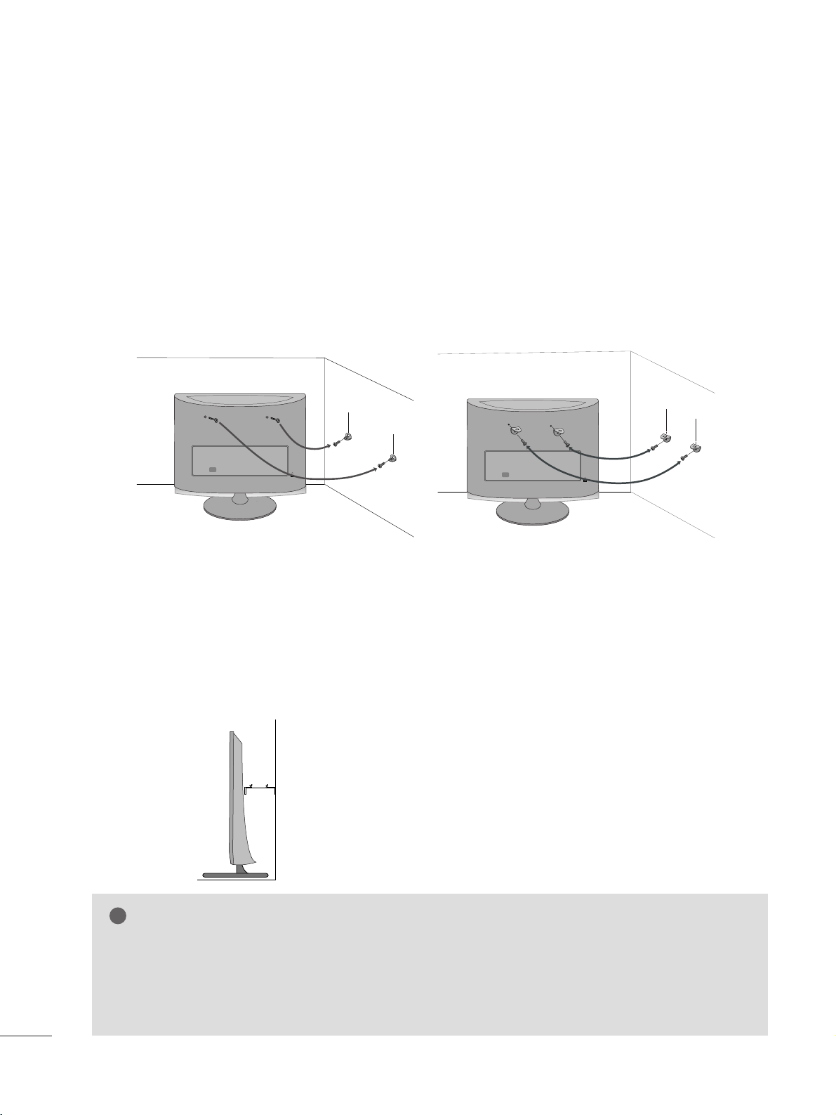
SECURING THE SET TO THE WALL TO PREVENT FALLING WHEN THE SET IS USED ON A STAND
We recommend that you set up the set close to a wall so it cannot fall over if pushed backwards.
Additionally, we recommend that the set be attached to a wall so it cannot be pulled in a forward direction,
potentially causing injury or damaging the product.
Caution: Please make sure that children don’t climb on or hang from the set.
■
Image shown may differ from your set.
■
Insert the eye-bolts (or set brackets and bolts) to tighten the product to the wall as shown in the picture.
* If your product has the bolts in the eye-bolts position before inserting the eye-bolts, loosen the bolts.
* Insert the eye-bolts or set brackets/bolts and tighten them securely in the upper holes.
Secure the wall brackets with the bolts (sold separately) to the wall. Match the height of the bracket that is
mounted on the wall to the holes in the product.
Ensure the eye-bolts or brackets are tightened securely.
1100
■
Use a sturdy rope or cord (sold separately) to tie the product. It is
safer to tie the rope so it becomes horizontal between the wall and the
product.
NOTE
!
G When moving the set, undo the cords first.
G Use a platform or cabinet strong enough and large enough to support the size and weight of the set.
G To use the set safely make sure that the height of the bracket on the wall and the one on the set are the
same.
1111
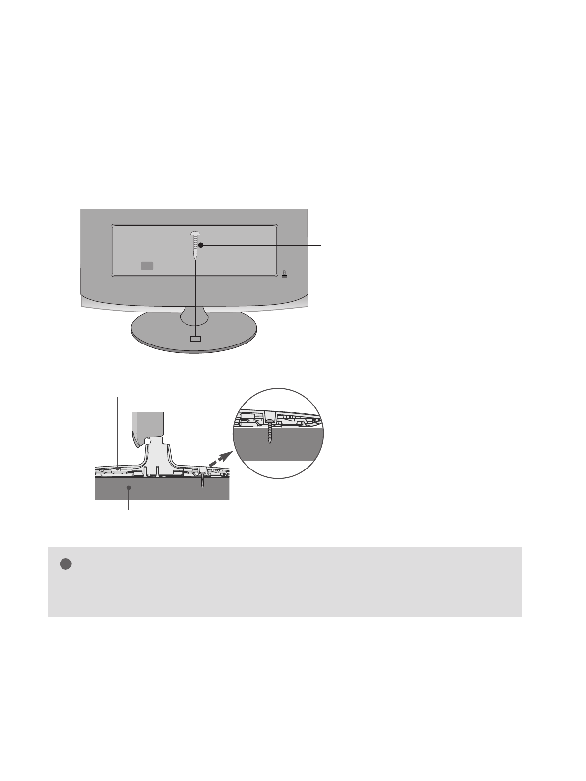
ATTACHING THE TV TO A DESK (Only M2762D)
The TV must be attached to desk so it cannot be pulled in a forward/backward direction,potentially causing
injury or damaging the product.Use only an attached screw.
■
Image shown may differ from your set.
WARNING
!
G To prevent TV from falling over,the TV should be securely attached to the floor/wall per installation
instructions. Tipping,shaking, or rocking the machine may cause injury.
1-Screw
(provided as parts of the product)
PREPARATION
Stand
Desk
1122
PREPARATION
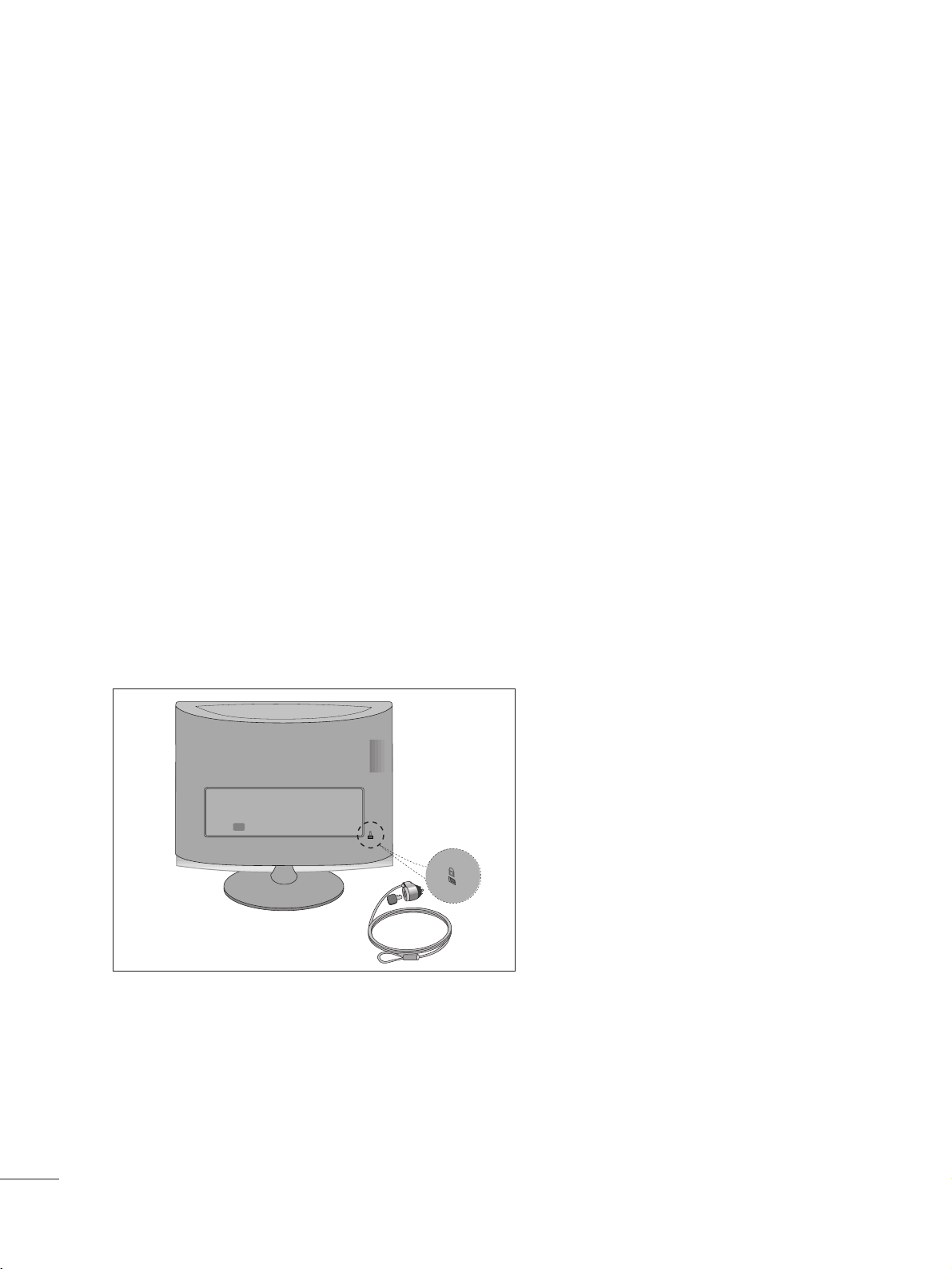
KENSINGTON SECURITY SYSTEM
- The product is equipped with a Kensington Security System connector on the back panel. Connect the
Kensington Security System cable as shown below.
- For detailed installation and use of the Kensington Security System, refer to the user’s guide provided with the
Kensington Security System.
For further information, contact
hhttttpp::////ww wwww ..kk eenn ssiinngg ttoonn ..cc oo mm
, the internet homepage of the Kensington
company. Kensington sells security systems for expensive electronic equipment such as notebook PCs and LCD
projectors.
NOTE
- The Kensington Security System is an optional accessory.
NOTES
a. If the product feels cold to the touch, there may be a small “flicker” when it is turned on.
This is normal, there is nothing wrong with product.
b. Some minute dot defects may be visible on the screen, appearing as tiny red, green, or blue spots. However, they
have no adverse effect on the monitor's performance.
c. Avoid touching the LCD screen or holding your finger(s) against it for long periods of time.
Doing so may produce some temporary distortion effects on the screen.
1133
ANTENNA/
CABLE IN
ANTENNA/
CABLE IN
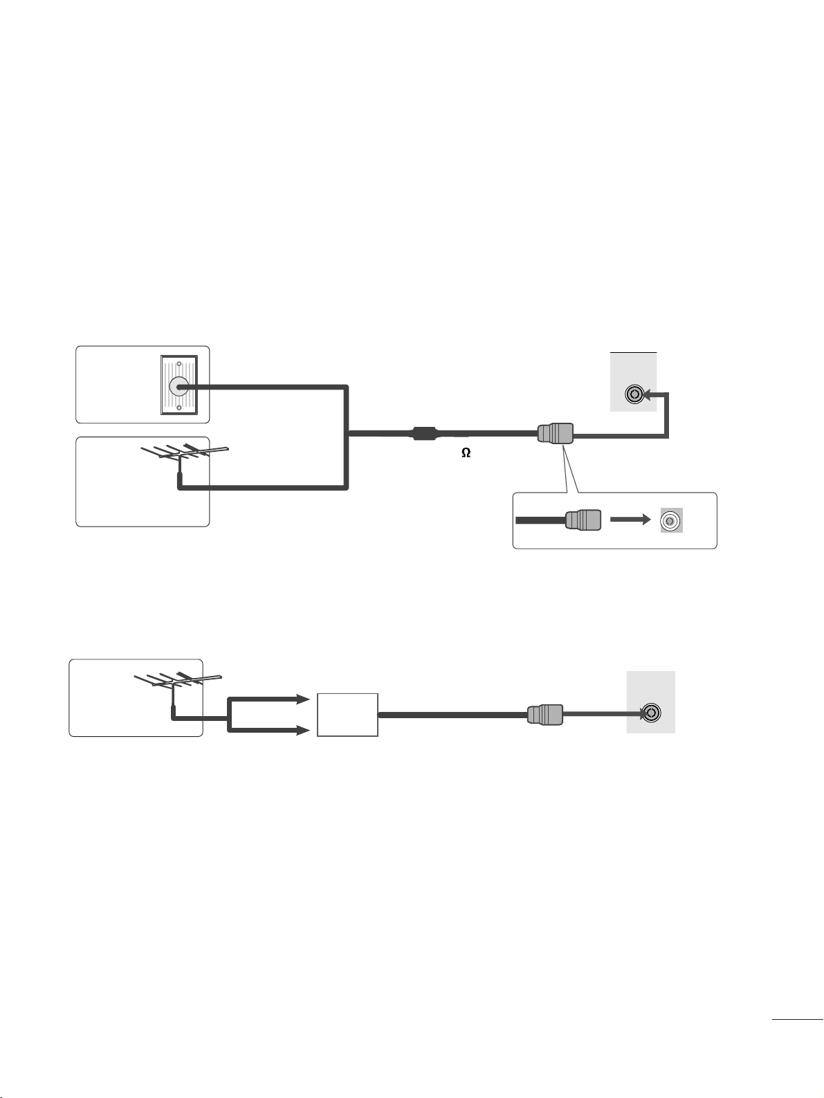
EXTERNAL EQUIPMENT SETUP
■
For optimum picture quality, adjust antenna direction.
■
An antenna cable and converter are not supplied.
■
To prevent equipment damage, never plug in any power cords until you have finished connecting all equipment.
Multi-family Dwellings/Apartments
(Connect to wall antenna socket)
Single-family Dwellings /Houses
(Connect to wall jack for outdoor antenna)
Outdoor
Antenna
(VHF, UHF)
Wal l
Antenna
Socket
RF Coaxial Wire (75 )
ANTENNA CONNECTION
Antenna
UHF
Signal
Amplifier
VHF
■
In poor signal areas, to get better picture quality, install a signal amplifier to the antenna as shown above.
■
If signal needs to be split for two TVs, use an antenna signal splitter for connection.
1144
EXTERNAL EQUIPMENT SETUP
Connect the SET-TOP outputs to the
CC OO MM PPOO NNEENNTT IINN
VV IIDD EEOO
sockets (Y P
B PR) on the set.
Connect the audio cable from the SET-TOP to
CC OOMMPPOO--
NN EENNTT IINN AA UUDD IIOO
sockets of the set.
Press the
IINN PPUUTT
button to select
CC oo mmppoonn eenn tt..
2
3
1
HD RECEIVER SETUP
■
To prevent the equipment damage, never plug in any power cords until you have finished connecting all equipment.
■
The image shown may be somewhat different from your set.
When connecting with a component cable
Signal
480i/576i
480p/576p
720p/1080i
10 8 0 p
Component
Yes
Yes
Yes
Yes
HDMI
No
Yes
Yes
Yes
VIDEO
COMPONENT
IN
AUDIO
Y
P
B
P
R
L
R
1
2
1155
EXTERNAL EQUIPMENT SETUP
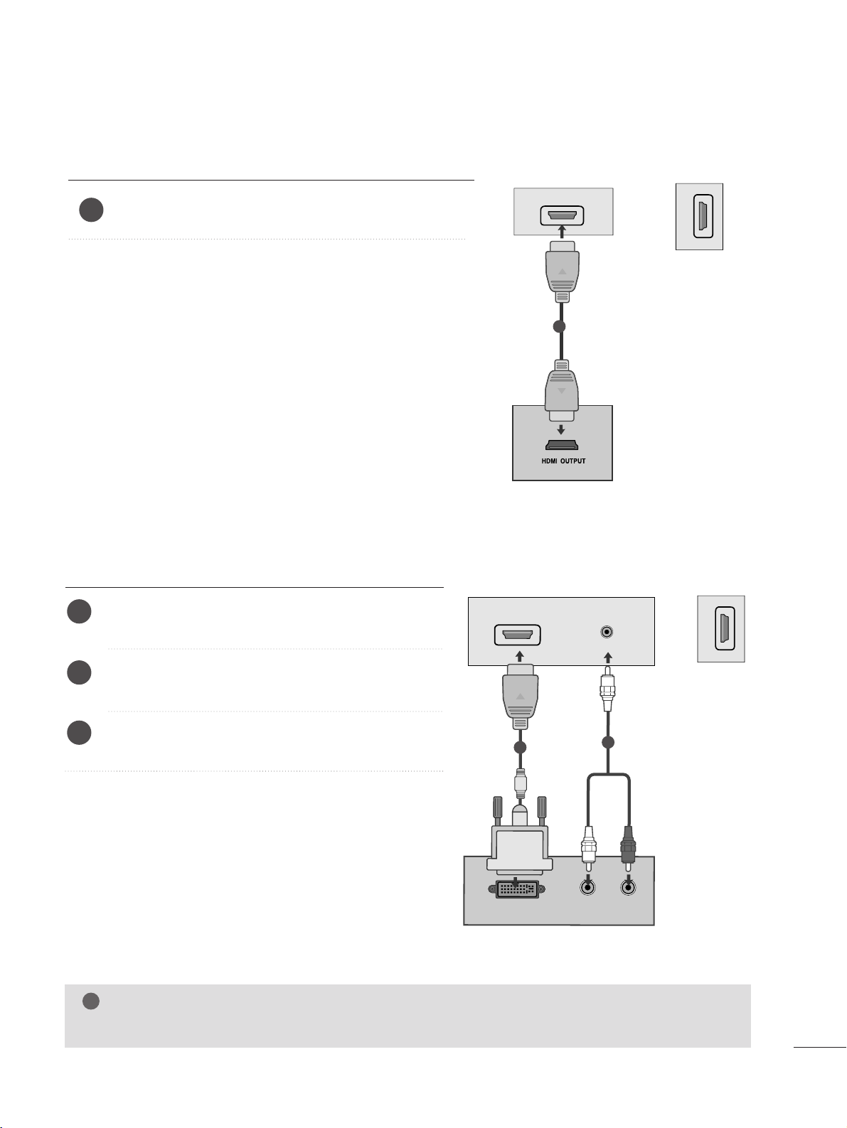
When connecting with a HDMI
Connect the HDMI output of the digital set-top box to the
HHDD MM II IINN
jack on the set.
or
1
Connect the digital set-top box to
HHDD MMII IINN
jack on
the set.
Connect the audio output of the digital set-top box to
the
AAUUDDIIOO IINN (( RRGG BB // DDVVII))
jack on the set.
Turn on the digital set-top box. (Refer to the owner’s
manual for the digital set-top box.
)
2
3
1
When connecting with a HDMI to DVI cable
HDMI IN
1
1
HDMI IN
2
HDMI IN
2
DVI OUTPUT
AUDIO
RL
AUDIO IN
(RGB/DVI)
HDMI IN
1
1
2
or
NOTE
!
G
HDMI Input does not support PC mode. If it is connected PC, the screen may not be displayed properly.
1166
EXTERNAL EQUIPMENT SETUP
DVD SETUP
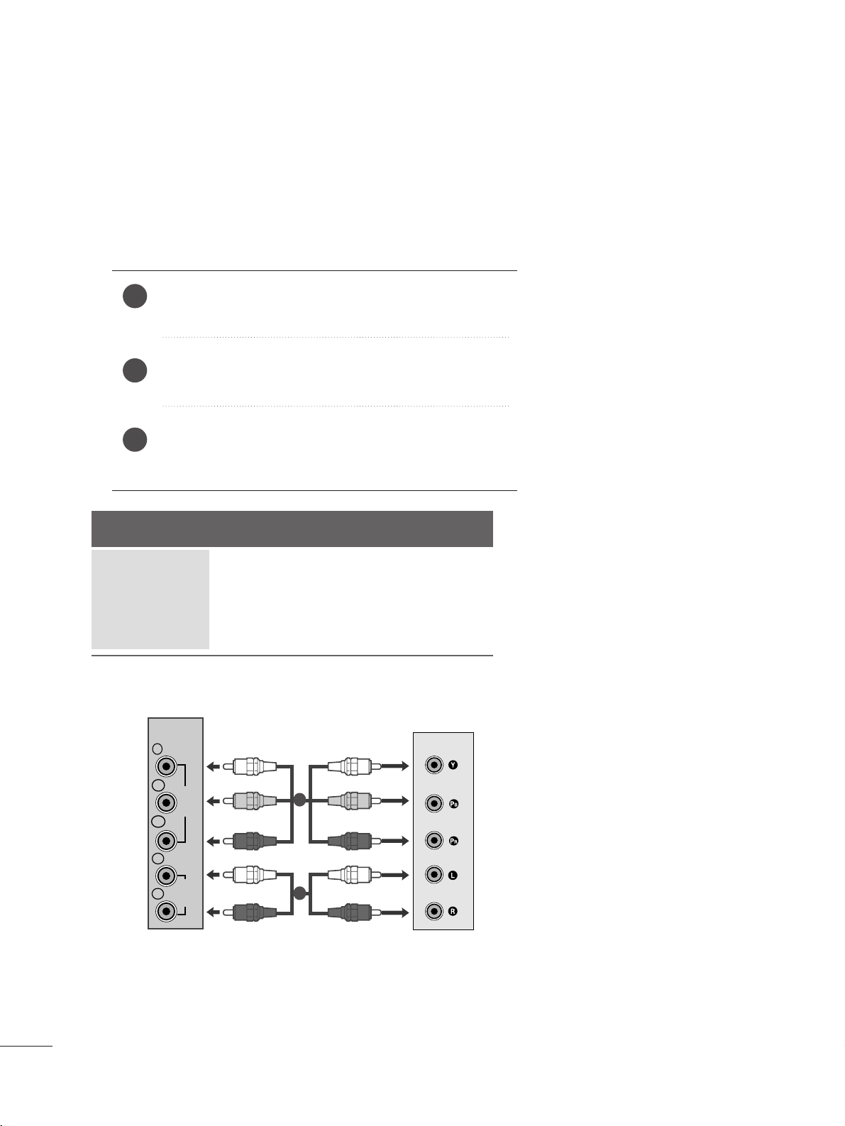
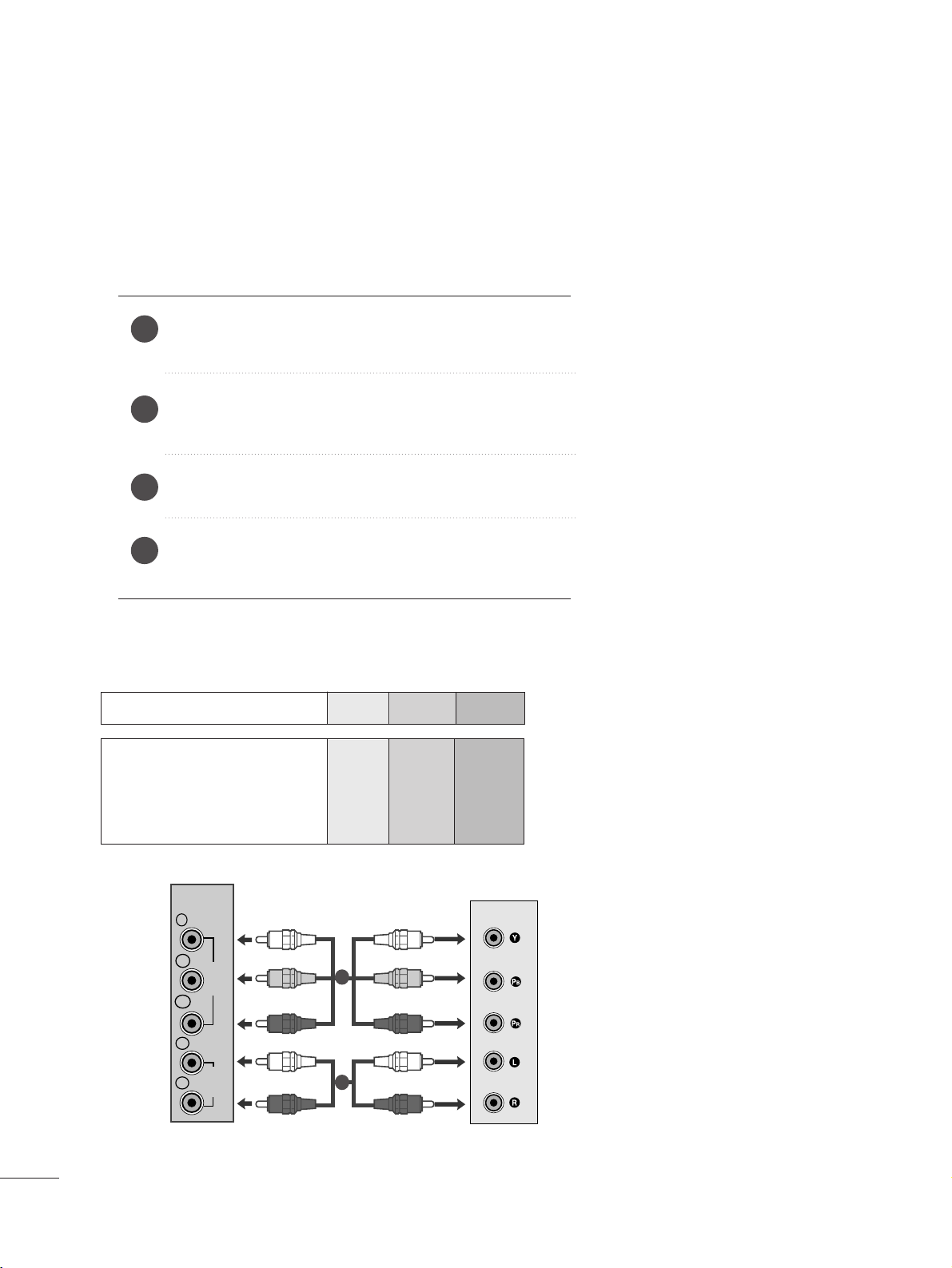
When connecting with a component cable
Component Input ports
To get better picture quality, connect a DVD player to the component input ports as shown below.
Component ports on the set
YPBP
R
Video output ports
on DVD player
Y
Y
Y
Y
P
B
B-Y
Cb
Pb
P
R
R-Y
Cr
Pr
Connect the video output sockets (Y P
B PR) of the DVD to
the
CC OOMMPPOO NN EENNTT II NN VVIIDD EEOO
sockets (Y P
B PR) of the set.
Connect the audio cable from the DVD to
CC OOMMPP OONN EENNTT
IINN AAUUDD IIOO
sockets of the set.
Press the
IINN PPUUTT
button to select
CCoomm ppoonn ee nntt
.
Press the
PPLL AAYY
button on the DVD.
The DVD playback picture appears on the screen.
2
3
4
1
1
2
COMPONENT
IN
Y
P
B
VIDEO
P
R
L
AUDIO
R
1177
EXTERNAL EQUIPMENT SETUP
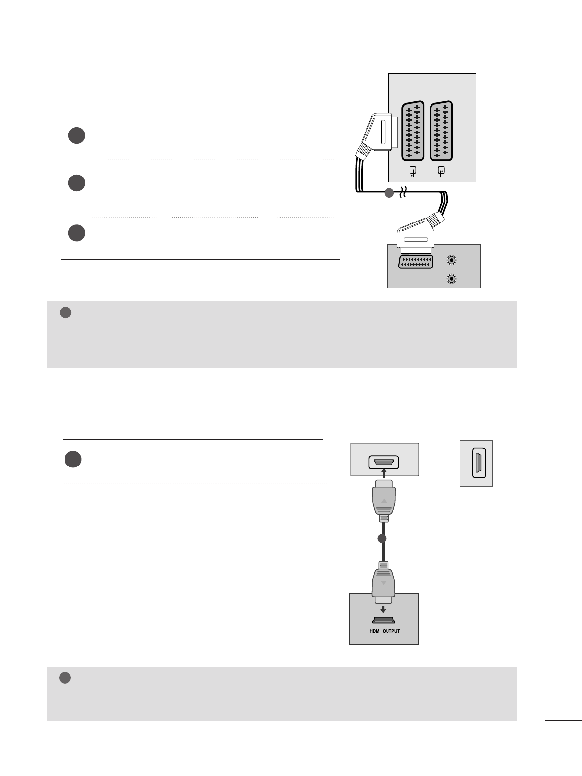
When connecting with a Euro Scart[DVD]
Connect the Euro scart socket of the DVD to the Euro scart
socket of the set.
Press the
IINN PPUUTT
button to select
AAVV 11
.
If connected to
AA VV 22
Euro scart socket, select
AA VV 22
input
source.
Press the
PPLL AAYY
button on the DVD.
The DVD playback picture appears on the screen.
2
3
1
When connecting HDMI cable
Connect the HDMI output of the DVD to the
HHDD MM II IINN
jack on the set.
or
1
G Set can receive the video and audio signal simultaneously by using a HDMI cable.
G If the DVD player does not support Auto HDMI, you need to set the DVD output resolution appropriately.
NOTE
!
NOTE
!
G Signal type RGB, i.e. the signals red, green and blue can only be selected for the Euro scart and the AV 1 can be
received. These signals are transmitted, for example, by a paid TV decoder, game machine or photo CD unit, etc.
G Please use shielded scart cable.
AUDIO
(L)
(R)
AUDIO/
VIDEO
AV 1 AV 2
1
HDMI IN
1
1
HDMI IN
2
1188
EXTERNAL EQUIPMENT SETUP
VCR SETUP
■
To avoid picture noise (interference), leave an adequate distance between the VCR and set.
■
Typically a still picture is shown on the VCR. If a user uses 4:3 picture format for a long time, an afterimage may
remain on the sides of the screen.
OUTPUT
SWITCH
ANT IN
R
S-VIDEO VIDEO
ANT OUT
L
ANTENNA/
CABLE IN
Wall Jack
Antenna
1
2
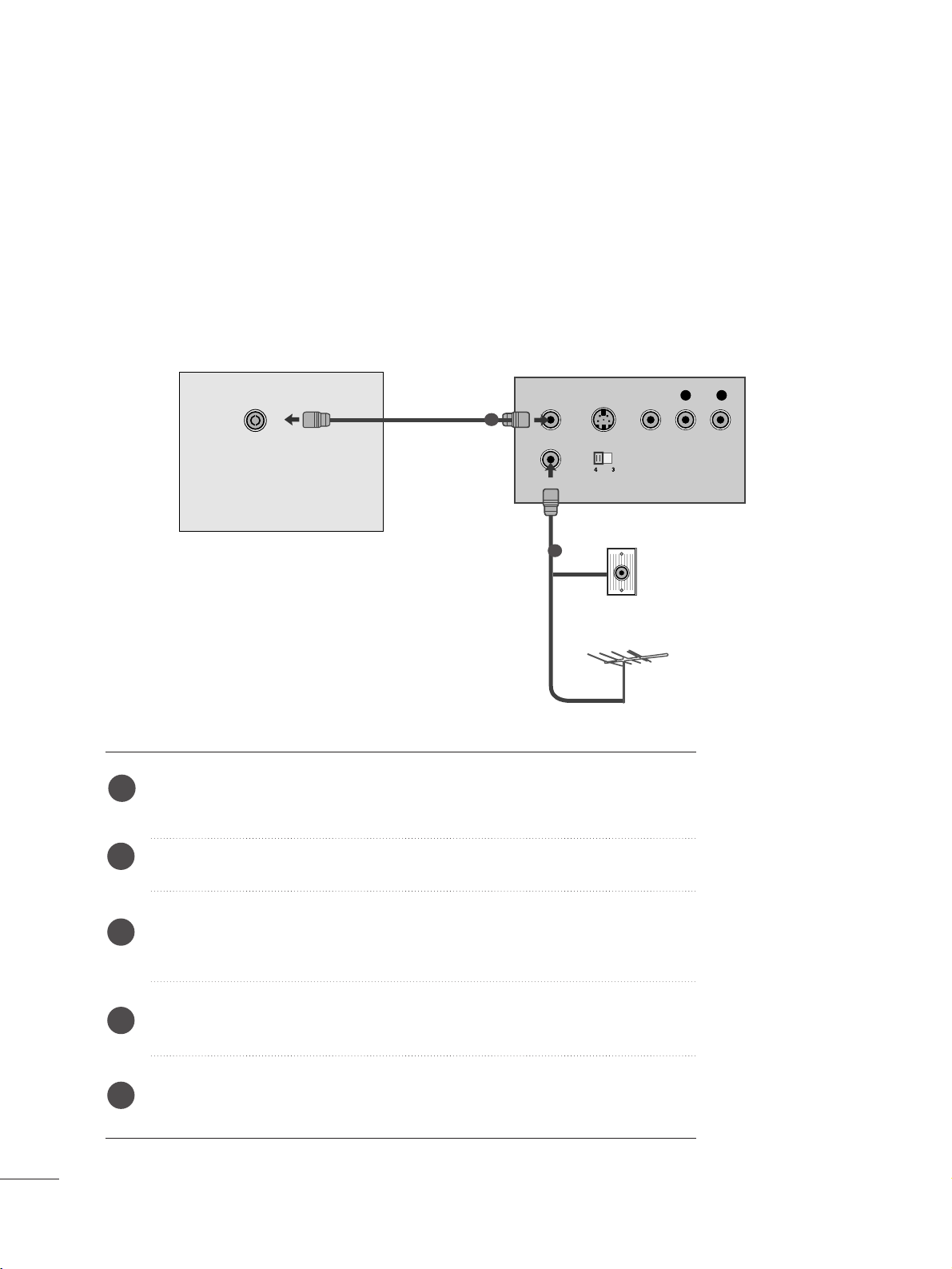
When connecting with an antenna
Connect the RF out socket of the VCR to the aerial socket of the set.
Connect the aerial cable to the RF aerial in socket of the VCR.
Store the VCR channel on a desired programme number using the ‘Manual programme tuning’ section.
Select the programme number where the VCR channel is stored.
Press the
PPLLAAYY
button on the VCR.
1
2
3
4
5
1199
EXTERNAL EQUIPMENT SETUP
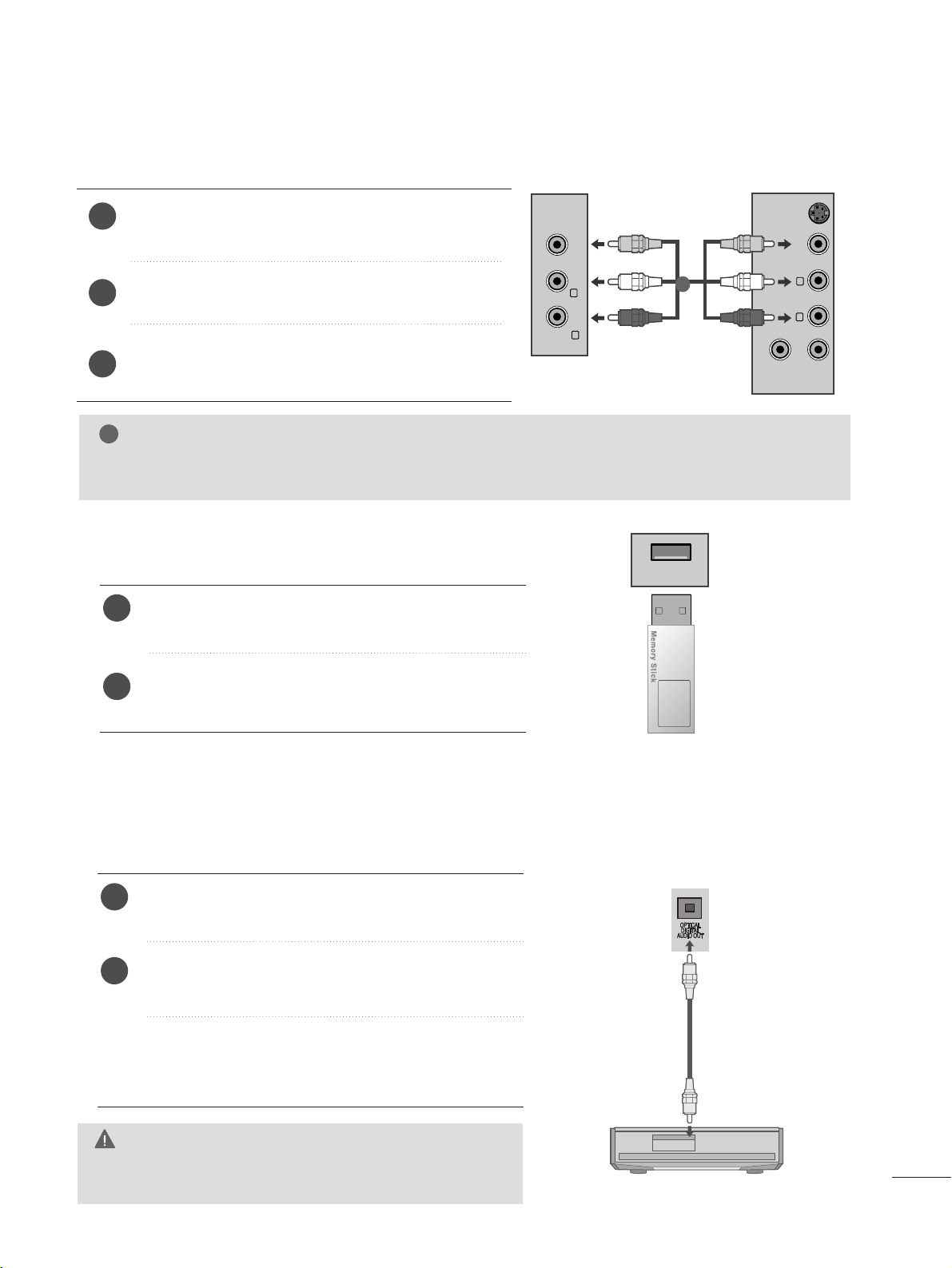
WWhheenn ccoonnnneeccttiinngg wwiitthh aa RRCCAA ccaabbllee
Connect the audio/video out sockets of the VCR to
AUDIO/VIDEO in sockets of the set.
Press the INPUT button to select AV3.
Press the PLAY button on the VCR.
The VCR playback picture appears on the screen.
2
3
1
NOTE
!
G
If you have a mono VCR, connect the audio cable from the VCR to the AUDIO L/MONO jack of the set.
VIDEO ANT IN
ANT OUT
S-VIDEO
L
R
VIDEO AUDIO
(MONO)
L
R
AV-IN 3
1
Connect the USB device to the
UUSSBB IINN
jacks on the
side of set.
After connecting the
UUSS BB IINN
jacks, you use the
UU SS BB
function. (
G
pp..9922
)
2
1
USB SETUP
USB IN
Connect one end of an optical cable to the TV Digital
Audio (Optical)Output port.
Connect the other end of the optical cable to the digital audio (Optical)input on the audio equipment.
Set the
““TT VV SSppeeaakkeerr ooppttiioonn -- OOffff ””
in the AUDIO
menu.(
G
pp..7711
). Refer to the external audio equipment
instruction manual for operation.
Sending the TV’s audio signal to external audio equipment via the Digital Audio Output (Optical) port.
If you want to enjoy digital broadcasting through 5.1-channel speakers, connect the OPTICAL DIGITAL AUDIO
OUT terminal on the back of TV to a DVD Home Theater (or amp).
2
1
DIGITAL AUDIO OUT SETUP
G
Do not look into the optical output port. Looking at the
laser beam may damage your vision.
CAUTION
2200
EXTERNAL EQUIPMENT SETUP
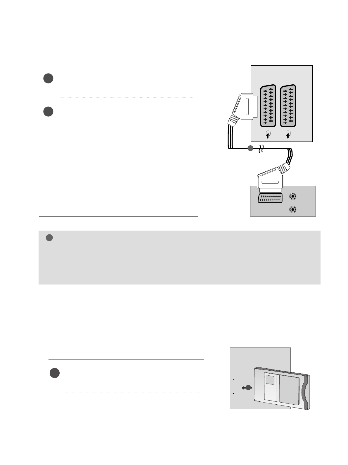
When connecting with a Euro Scart[VCR]
Connect the Euro scart socket of the VCR to the Euro
scart socket of the set.
Press the
PPLL AAYY
button on the VCR.
If your VCR outputs an AV switching signal via the Scart
lead, the set will auto switch to
AAVV 11
mode on start of
playback, but if you want to keep on watching in TV mode,
press the
D
//
E or NUMBER buttons.
If connected to
AA VV 22
Euro scart socket, select
AA VV 22
input
source.
Otherwise press the
IINN PPUUTT
button on the remote control
handset to select
AAVV 11
. The VCR playback picture appears
on the screen.
You can also record programmes received by the set on
video tape.
2
1
NOTE
!
G
Signal type RGB, i.e. the signals red, green and blue can only be selected for the Euro scart and the AV 1
can be received. These signals are transmitted, for example, by a paid TV decoder, game machine or photo
CD unit, etc.
G
Please use shielded scart cable.
Insert the CI Module to
PPCCMMCCII AA
(Personal Computer
Memory Card International Association)
CC AARRDD SS LL OOTT
of set as shown.
For further information, see p. 40.
1
INSERTION OF CI MODULE
PCMCIA
CARD SLOT
TVTVTV
-- TT oo vvii eeww tt hhee ssccrraa mmbbllee dd ((ppaaiidd)) sseerr vviiccee ss iinn ddiigg iitt aall TT VV
mm oo ddee ..
-- TT hhii ss ffee aattuurr ee ii ss nnoott aavvaaiillaa bbllee iinn aallll ccoouu nnttrriieess ..
1
AUDIO/
VIDEO
AV 1V 1 AV 2V 2
AUDIO
(L)
(R)
1
2211
EXTERNAL EQUIPMENT SETUP
PC SETUP
This product provides Plug and Play capability, meaning that the PC adjusts automatically to the set's settings.
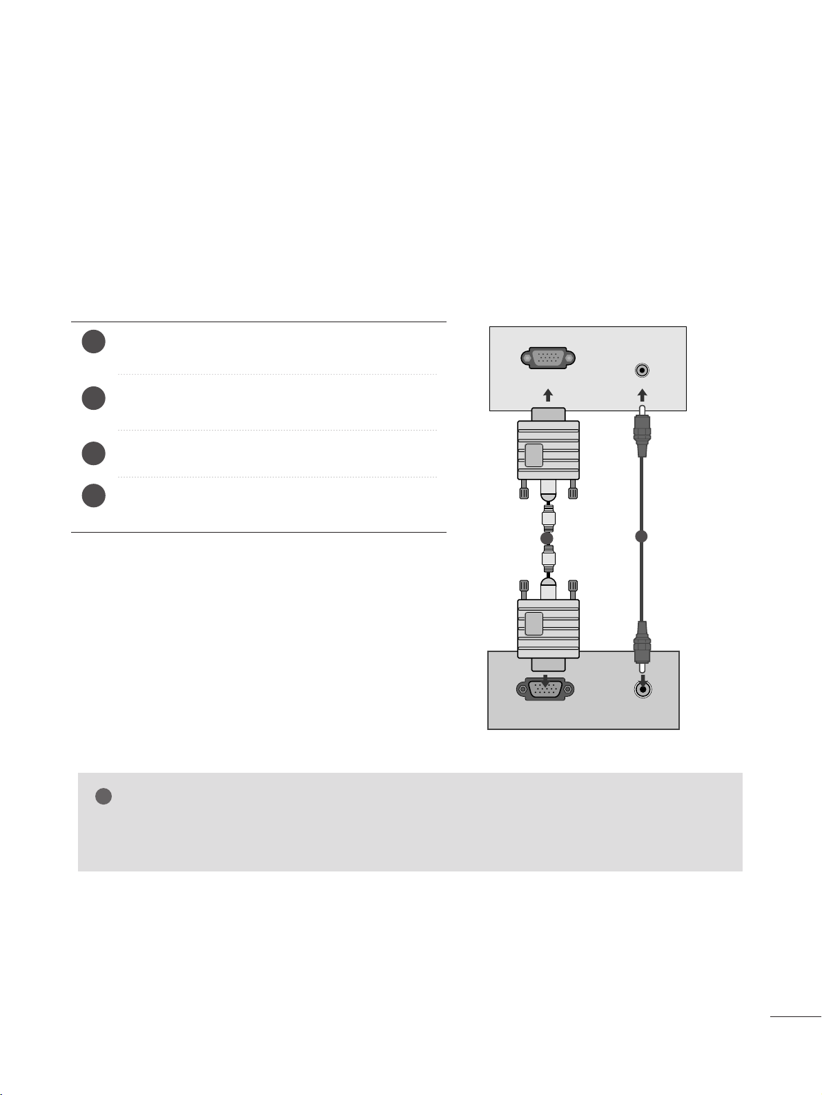
When connecting with a D-sub 15 pin cable
4
Connect the signal cable from the monitor output socket of
the PERSONAL COMPUTER to the PC input socket of the set.
Connect the audio cable from the PC to the
AA UUDD IIOO IINN
(( RR GGBB// DD VVII))
sockets of the set.
Press the INPUT button to select
RR GGBB
.
Switch on the PC, and the PC screen appears on the set.
The set can be operated as a PC monitor.
2
3
1
RGB OUTPUT
AUDIO
AUDIO IN
(RGB/DVI)
RGB IN (PC)
1
2
NOTE
!
G
You must use shielded signal interface cables (D sub 15 pin cable, DVI cable) with ferrite cores to maintain
standard compliance for the product.
2222
EXTERNAL EQUIPMENT SETUP
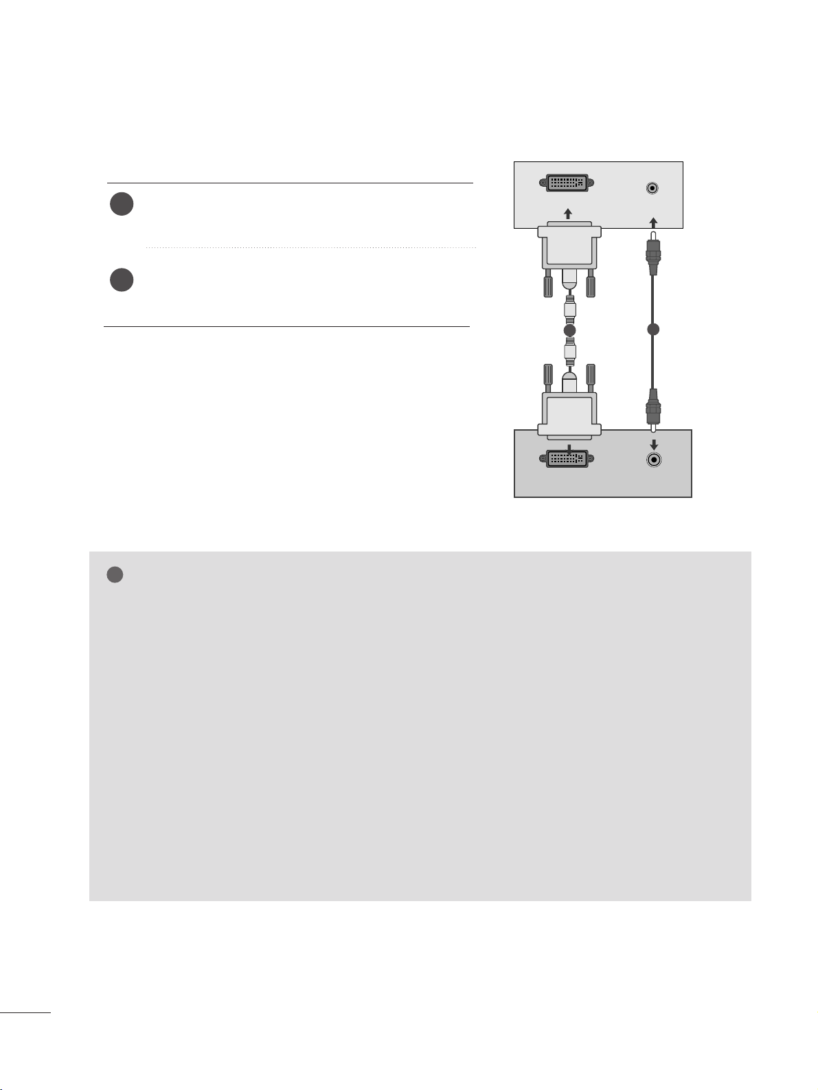
When connecting with a DVI cable
Connect the DVI output of the PC to the
DDVVII--DD IINN
jack on the set.
Connect the audio cable from the PC to the
AA UU DDII OO
IINN ((RRGGBB// DDVVII))
sockets of the set.
2
1
NOTE
!
G
If the set is cold, there may be a small “flicker” when the
set is switched on. This is normal, there is nothing wrong
with the set.
G
If possible, use the 1360x768 @ 60 Hz video mode to
obtain the best image quality for your LCD monitor. If
used with other resolutions, some scaled or processed
pictures may appear on the screen. The set has been
preadjusted to the mode 1360 x 768 @ 60
Hz.
((MM11996622DD))
G
If possible, use the 1600 x 900 @ 60 Hz video mode to
obtain the best image quality for your LCD monitor. If
used with other resolutions, some scaled or processed
pictures may appear on the screen. The set has been
preadjusted to the mode 1600 x 900 @ 60
Hz.
((MM22006622DD))
G
If possible, use the 1920 x 1080 @ 60 Hz video mode
to obtain the best image quality for your LCD monitor. If
used with other resolutions, some scaled or processed
pictures may appear on the screen. The set has been
preadjusted to the mode 1920 x 1080 @ 60 Hz.
((MM22226622DD//MM22336622DD//MM22776622DD))
G
Some dot defects may appear on the screen, like Red,
Green or Blue spots. However, this will have no impact or
effect on the monitor performance.
G
Do not press the LCD screen with your finger for a long
time as this may produce some temporary distortion
effects on the screen.
G
Avoid keeping a fixed image on the set’s screen for prolonged periods of time. The fixed image may become
permanently imprinted on the screen; use a screen saver
when possible.
AUDIO
DVI OUTPUT
AUDIO IN
(RGB/DVI)
DVI-D IN (PC)
1
2
2233
EXTERNAL EQUIPMENT SETUP
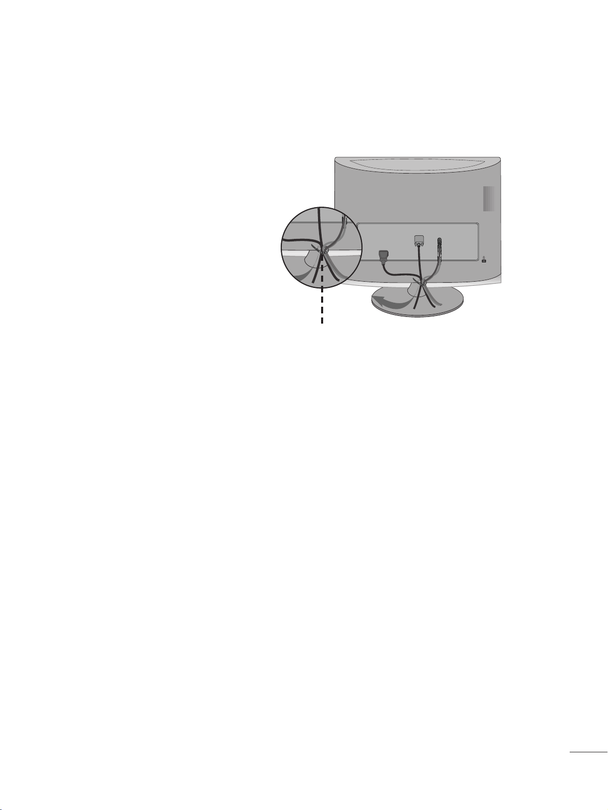
Tie cables together with a cable tie as shown in the
illustration.
Cable tie
R
R
BACK COVER FOR WIRE ARRANGEMENT
2244
EXTERNAL EQUIPMENT SETUP
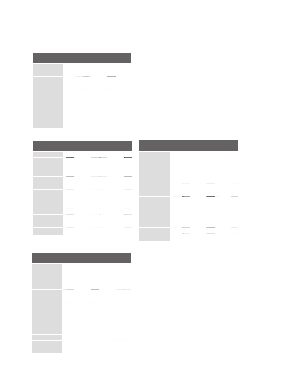
<M1962D>
RGB/DVI[PC]
HDMI[DTV] (Not Support PC)
60
60
50
50
60
60
60
60
50
24
30
50
60
60
31.469
31.5
31.25
37.5
44.96
45
33.72
33.75
28.125
27
33.75
56.25
67.43
67.5
Resolution
720x480/60p
720x576/50p
1280x720/60p
1280x720/50p
Horizontal
Frequency(kHz)
Vertical
Frequency(Hz)
1920x1080/60i
1920x1080/50i
1920x1080/24p
1920x1080/30p
1920x1080/50p
Resolution
Horizontal
Frequency(kHz)
Vertical
Frequency(Hz)
31.469 60
37.5 75
37.879 60
46 .875 75
48.363 60
60.123 75
47.776 6 0
49.306 60
47.712 60
47.7 60
<M2262D/M2362D/M2762D>
Resolution
640x480
800x600
720x400
1024x768
Horizontal
Frequency(kHz)
Vertical
Frequency(Hz)
31.468 70
31.469 60
37.500 75
37.879 60
46.875 75
48.363 60
60.123 75
67.500 75
63.981 60
79.976 75
64.674 60
65.290 60
75.000 60
66.587 60
1280x1024
1152x864
1680x1050
1920x1080
1600x1200
640x480
800x600
1024x768
1280x768
1360x768
1920x1080/60p
<M2062D>
Resolution
Horizontal
Frequency(kHz)
Vertical
Frequency(Hz)
25.175 70
31.468 70
31.469 60
37.5 75
37.879 60
46 .875 75
49.725 65
48.363 60
60.123 75
68.681 75
63.981 60
79.976 75
60 60
640x480
800x600
832x624
1024x768
720x350
720x400
1152x870
1280x1024
1280x1024
1600x900
1280x800
2255
WATCHING TV /PROGRAMME CONTROL
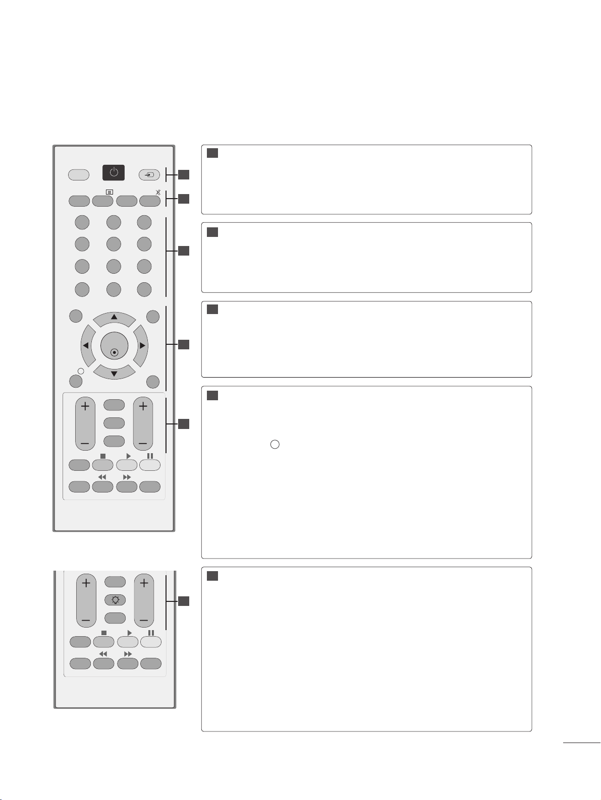
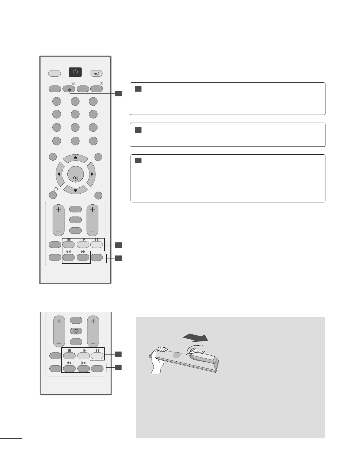
REMOTE CONTROL KEY FUNCTIONS
When using the remote control, aim it at the remote control sensor on the set.
OK
MENU EXIT
GUIDE
123
456
789
0
Q.VIEW
LIST
TV/PC INPUT
POWER
VOL PR
I/II
MUTE
TEXT
RETURN
FAV
INFO
i
TV/RADIO
*
Q.MENU
T.OPT MARK
SUBTITLE
VOL PR
RETURN
LIGHTING
FAV
Q.MENU
T.OPT MARK
SUBTITLE
POWER
TV/PC
INPUT
A TYPE
B TYPE
Switches the set on or off.
Selects TV or PC mode.
External input mode rotates in regular sequence.
TV/RADIO
I/II
MUTE
Selects Radio or TV channel.
Selects the sound output.(Refer to the p.73~74 )
Switches the sound on or off.
0~9 number
button
LIST
Q.VIEW
Selects a programme.
Selects numbered items in a menu.
Displays the programme table.(Refer to the p.41)
Returns to the previously viewed programme.
MENU
EXIT
INFO i
GUIDE
THUMBSTICK
(Up/Down/Left/Right)
OK
Selects a menu. (Refer to the p.30)
Clears all on-screen displays.
Shows the present screen information.
Shows programme schedule.(Refer to the p.42~45)
Allows you to navigate the on-screen menus and adjust the
system settings to your preference.
Accepts your selection or displays the current mode.
VOLUME UP
/DOWN
RETURN
*
LIGHTING
FAV
Programme
UP/DOWN
Adjusts the volume.
Allows the user to move back one step in an interactive application, EPG or other user interaction function.
A TYPE : No function
B TYPE : Press the Lighting button to turn the decoration light-
ing on/off.
Displays the selected favourite programme.(Refer to the p.41)
Selects a programme.
11
11
22
33
44
55
22
33
44
55
55
2266
WATCHING TV /PROGRAMME CONTROL
Installing Batteries
■
Open the battery compartment cover on the back and install the
batteries matching correct polarity (+ with +, - with -).
■
Install two 1.5 V AAA batteries. Don’t mix old or used batteries with
new ones.
■
Close cover.
■
To remove the batteries, perform the installation actions in reverse.
USB Menu
control buttons
Controls USB menu (Photo List and Music
List)
(Refer to the p.92)
TELETEXT
BUTTONS
These buttons are used for teletext.
For further details, see the ‘Teletext’ section.
(Refer to the p.100~10 2 )
11
22
33
Q.MENU
MARK
Select the desired quick menu source.
(Refer to the p.29)
Check and un-check programmes in the recorded set
menu.
OK
MENU EXIT
GUIDE
123
456
789
0
Q.VIEW
LIST
TV/PC INPUT
POWER
VOL PR
I/II
MUTE
TEXT
RETURN
FAV
INFO
i
TV/RADIO
*
Q.MENU
T.OPT MARK
SUBTITLE
11
22
33
VOL PR
RETURN
LIGHTING
FAV
Q.MENU
T.OPT MARK
SUBTITLE
A TYPE
B TYPE
22
33
2277
WATCHING TV /PROGRAMME CONTROL
TURNING ON THE TV
- When your TV is turned on, you will be able to use its features.
Firstly,connect the power cord correctly and check the main power( r / I )on the TV.
SSeett IIDD :: OOffff
In standby mode to turn TV on, press the INPUT or PR
D
//
E
button on the TV or press the POWER button on the
remote control and the TV will switch on.
SSeett IIDD :: OOnn
In standby mode to turn TV on,pr ss the INPUT or PR
D
//
E
button on the TV or press the POWER, INPUT, PR
++
//--
or NUMBER button on the remote control and the TV will switch on.
2
1
Initializing setup
Note:
a. If you close without completing the initial setting, the Initial Setting menu can be displayed again.
b. Press the RETURN button to change the current OSD to the previous OSD.
c. For those countries without confirmed DTV broadcasting standards, some DTV featur s might not work, depend-
ing on the DTV broadcasting environment.
d. "
HHoommee UUssee
” mode is the optimal setting for home environments, and is the TV's default mode.
e. "
SSttoorree DDeemmoo
"mode is the optimal setting for store environments. If a user modifies image quality data, “
SSttoorree
DDeemmoo
” mode initializes the product to the image quality set by us after a certain period of time.
f. The mode (
HHoommee UUssee, SSttoorree DDeemmoo
) can be changed by executing
MMooddee SSeettttiinngg
in the
OOPPTTIIOONN
menu.
If the OSD (On Screen Display) is displayed on the screen after turning on the TV, you can adjust the
LLaanngguuaaggee, MMooddee SSee tt tt ii nngg, CC oo uunn ttrr yy, AA uuttoo ttuunniinngg
.
2288
WATCHING TV /PROGRAMME CONTROL
OK
MENU EXIT
GUIDE
123
456
789
0
Q.VIEW
LIST
TV/PC INPUT
POWER
VOL PR
I/II
MUTE
TEXT
RETURN
FAV
INFO
i
TV/RADIO
*
Q.MENU
T.OPT MARK
SUBTITLE
VOL PR
RETURN
FAV
Q.MENU
T.OPT MARK
SUBTITLE
LIGHTING
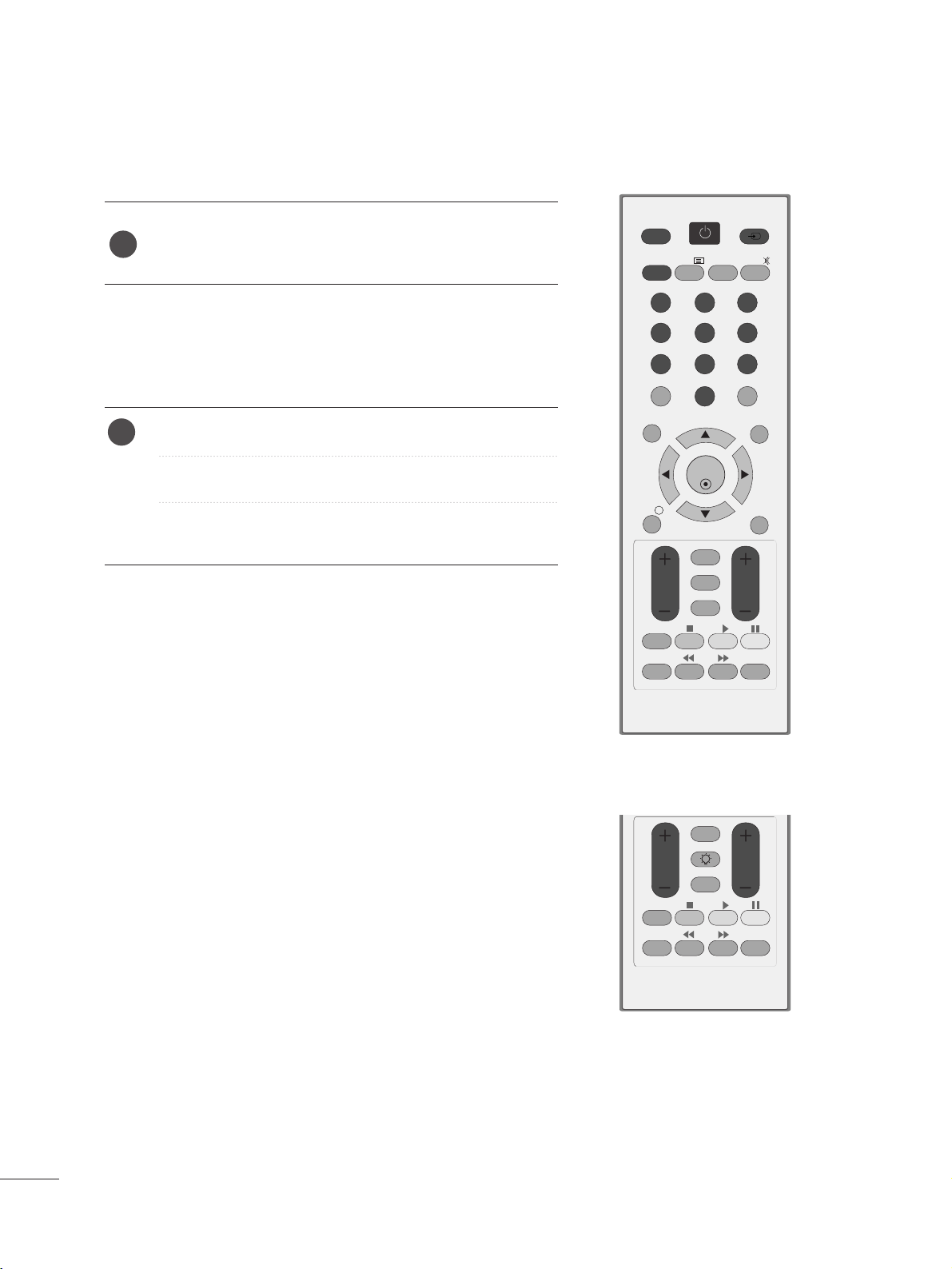
PROGRAMME SELECTION
Press the
PPRR ++ or--
or NUMBER buttons to select a pro-
gramme number.
1
VOLUME ADJUSTMENT
Press the VOL
++ or--
button to adjust the volume.
If you want to switch the sound off, press the MUTE button.
You can cancel this function by pressing the MUTE, VOL
++
or--, or I/II button.
1
A TYPE
B TYPE
 Loading...