


Order Number : GETEC-C1-09-204 FCC Class B Certification
Test Report Number : GETEC-E3-09-117 Page 1 / 1
APPENDIX G
: USER’S MANUAL
EUT Type: LCD TV/Monitor
FCC ID.: BEJM2262DL
Make sure to read the Safety Precautions before
using the product.
Keep the User's Guide(CD) in an accessible place
for furture reference.
See the label attached on the product and give the
information to your dealer when you ask for service.
OWNER’S MANUAL
M2262D
M2362D
M2762D
1
Safety Instructions
1
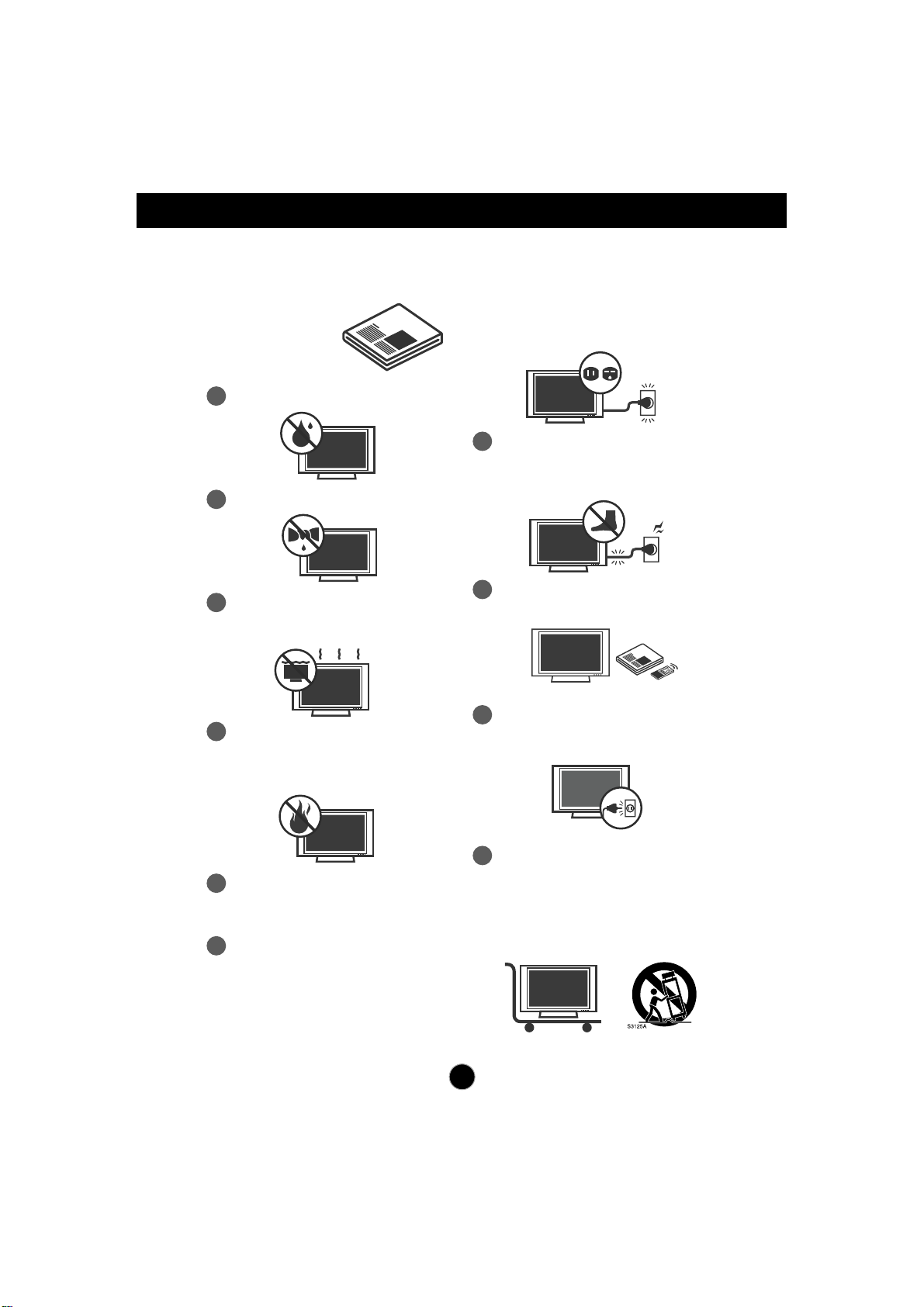
Do not use this apparatus near water.
Read these instructions.
Keep these instructions.
Heed all warnings.
Follow all instructions.
IMPORTANT SAFETY INSTRUCTIONS
2
Clean only with dry cloth.
3
Do not block any ventilation openings.
Install in accordance with the
manufacturer’s instructions.
4
Do not install near any heat sources such
as radiators, heat registers, stoves, or other
apparatus (including amplifiers) that
produce heat.
5
When mounting a TV on the wall, make
sure not to install TV by the hanging power
and signal cables on the back of the TV.
6
Do not defeat the safety purpose of the
polarized or grounding-type plug. A
polarized plug has two blades with one
wider than the other. A grounding type plug
has two blades and a third grounding
prong, The wide blade or the third prong
are provided for your safety.
7
Protect the power cord from being walked
on or pinched particularly at plugs,
convenience receptacles, and the point
where they exit from the apparatus.
If the provided plug does not fit into your
outlet, consult an electrician for
replacement of the obsolete outlet.
8
Only use attachments/accessories
specified by the manufacturer.
9
Unplug this apparatus during lightning
storms or when unused for long periods of
time.
10
Use only with the cart, stand, tripod,
bracket, or table specified by the
manufacturer, or sold with the apparatus.
When a cart is used, use caution when
moving the cart/apparatus combination to
avoid injury from tip-over.
2
Safety Instructions
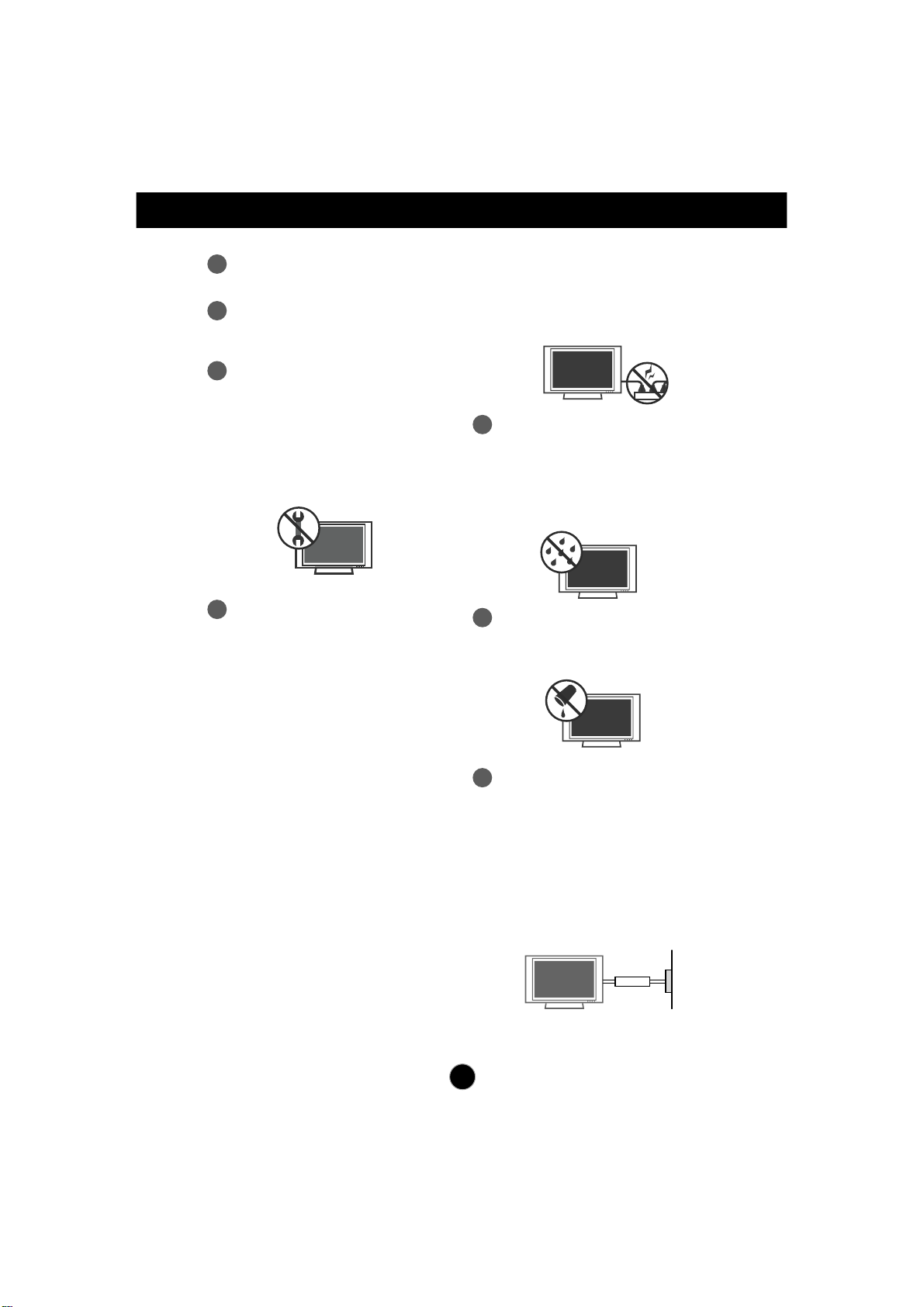
11
Never touch this apparatus or antenna
during a thunder or lighting storm.
12
Do not allow an impact shock or any
objects to fall into the product, and do not
drop onto the screen with something.
13
Refer all servicing to qualified service
personnel. Servicing is required when the
apparatus has been damaged in any
way, such as power-supply cord or plug
is damaged, liquid has been spilled or
objects have fallen into the apparatus,
the apparatus has been exposed to rain
or moisture, does not operate normally,
or has been dropped.
15
WARNING - To reduce the risk of fire or
electrical shock, do not expose this product
to rain, moisture or other liquids. Do not
touch the TV with wet hands. Do not install
this product near flammable objects such
as gasoline or candles or expose the TV to
direct air conditioning.
Do not move the TV with the power cord
plugged in. Do not use a damaged or loose
power cord. Be sure do grasp the plug
when unplugging the power cord. Do not
pull on the power cord to up unplug the TV.
16
Do no expose to dripping or splashing and
do not place objects filled with liquids, such
as vases, cups, etc. on or over the
apparatus (e.g. on shelves above the unit).
17
GROUNDING
Ensure that you connect the earth ground
wire to prevent possible electric shock (i.e.
a TV with a three-prong grounded AC plug
must be connected to a three-prong
grounded AC power outlet). If grounding
methods are not possible, have a qualified
electrician install a separate circuit breaker.
Do not try to ground the unit by connecting
it to telephone wires, lightening rods, or gas
pipes.
Power
Supply
Short-circuit
Breaker
14
CAUTION concerning the Power Cord:
It is recommend that appliances be placed
upon a dedicated circuit; that is, a single
outlet circuit which powers only that
appliance and has no additional outlets or
branch circuits. Check the specification
page of this owner's manual to be certain.
Do not connect too many appliances to the
same AC power outlet as this could result
in fire or electric shock.
Do not overload wall outlets. Overloaded
wall outlets, loose or damaged wall outlets,
extension cords, frayed power cords, or
damaged or cracked wire insulation are
dangerous. Any of these conditions could
result in electric shock or fire. Periodically
examine the cord of your appliance, and if
its appearance indicates damage or
deterioration, unplug it, discontinue use of
the appliance, and have the cord replaced
with an exact replacement part by an
authorized servicer. Protect the power cord
from physical or mechanical abuse, such
as being twisted, kinked, pinched, closed in
a door, or walked upon. Pay particular
attention to plugs, wall outlets, and the
point where the cord exits the appliance.
Safety Instructions
3
19
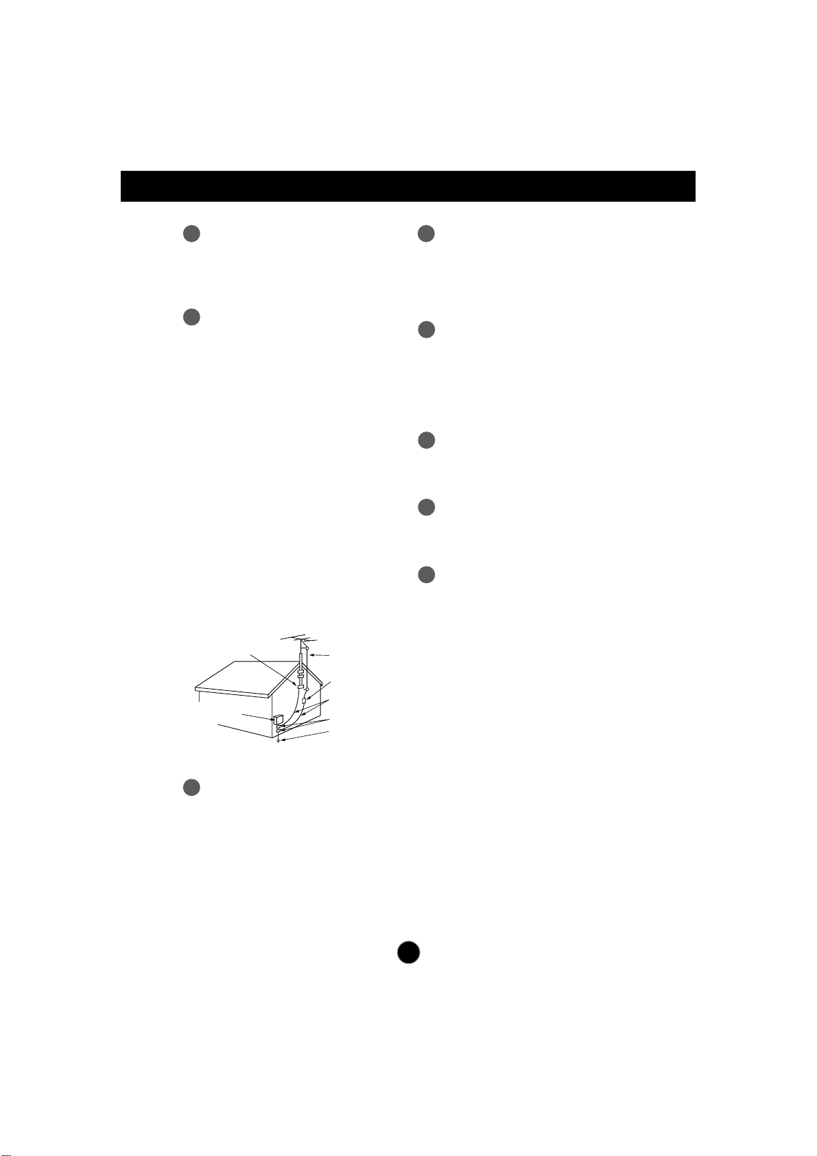
ANTENNAS
Outdoor antenna grounding
If an outdoor antenna is installed, follow the
precautions below. An outdoor antenna
system should not be located in the vicinity
of overhead power lines or other electric
light or power circuits, or where it can come
in contact with such power lines or circuits
as death or serious injury can occur.
Be sure the antenna system is grounded
so as to provide some protection against
voltage surges and built-up static charges.
Section 810 of the National Electrical Code
(NEC) in the U.S.A. provides information
with respect to proper grounding of the
mast and supporting structure, grounding
of the lead-in wire to an antenna discharge
unit, size of grounding conductors, location
of antenna discharge unit, connection to
grounding electrodes and requirements for
the grounding electrode.
Antenna grounding according to the
National Electrical Code, ANSI/NFPA 70
20
Cleaning
When cleaning, unplug the power cord and
scrub gently with a soft cloth to prevent
scratching. Do not spray water or other
liquids directly on the TV as electric shock
may occur. Do not clean with chemicals
such as alcohol, thinners or benzene.
22
Ventilation
Install your TV where there is proper
ventilation. Do not install in a confined
space such as a bookcase. Do not cover
the product with cloth or other materials
(e.g.) plastic while plugged in. Do not install
in excessively dusty places.
23
If you smell smoke or other odors coming
from the TV or hear strange sounds,
unplug the power cord contact an
authorized service center.
24
As long as this unit is connected to the AC
wall outlet, it is not disconnected from the
AC power source even if the unit is turned
off.
25
On Disposal
The fluorescent lamp used in this product
contains a small amount of mercury.
Do not dispose of this product with general
household waste.
Disposal of this product must be carried out
in accordance to the regulations of your
local authority.
NEC: National Electrical Code
Ground clamps
Antenna lead-in wire
Antenna discharge unit
(NEC Section 810-20)
Grounding conductors
(NEC Section 810-21)
Ground clamps
Power service grounding
electrode system
(NEC Art 250 Part H)
Electric service
equlpment
18
DISCONNECTING DEVICE
The power supply cord is used as the main
discon nection device. Ensure that the
socket outlet is easily accessible after
installation.
21
Moving
Make sure the product is turned off,
unplugged and all cables have been
removed. It may take 2 or more people to
carry larger TVs. Do not press against or
put stress on the front panel of the TV.
Pince de mise à la terre
Équipement électrique
Fil d entrée dantenne
Décharge d antenne
(section 810-20 du NEC)
Conducteur mis à la terre
(section 810-21 du NEC)
Pince de mise à la terre
Système d électrode
de mise à la terre (article 250,
section H du NEC)
1
PREPARATION
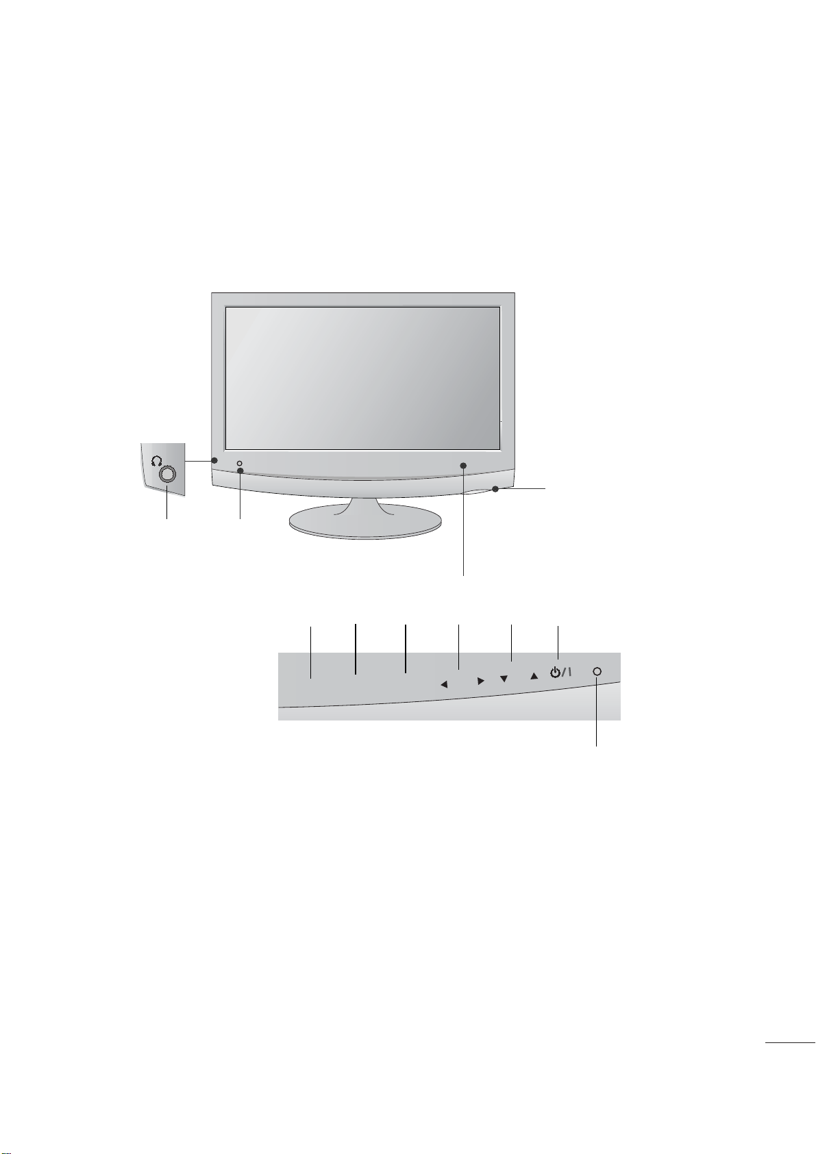
FRONT PANEL CONTROLS
■
This is a simplified representation of the front panel. The image shown may be somewhat different from your
set.
INPUT
Button
INPUT
MENU
CH
VOL
ENTER
MENU
Button
OK
Button
VOLUME
Buttons
CHANNEL
Buttons
Powe r
Button
Headphone
Jack
IR receiver
(Remote controller
receiver)
Light Sensor
This is lens for light sensor
select outside luminance,
when setting AUTO
BRIGHT ON.
Power Indicator
illuminates blue when the
set is switched on.
Note:You can adjust
Power indicator in the
OPTION menu.
2
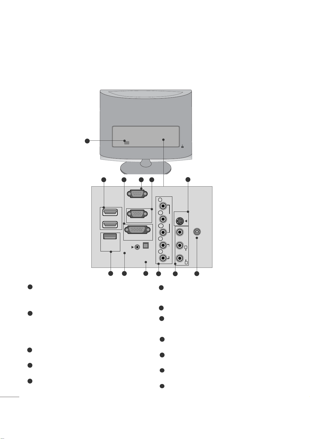
PREPARATION
BACK PANEL INFORMATION
■
This is a simplified representation of the back panel. The image shown may be somewhat different from your
set.
2
9
10 11
1
87
12
5
6
3 4
Power Cord Socket
This set operates on AC power. The voltage is indicated
on the Specifications page. Never attempt to operate
the set on DC power.
HDMI Input
High definition inputs. These two inputs accept TV
Video, not PC Video. They also accept TV Video from a
DVI connection when using an adapter. The HDMI
inputs support video and audio. When using an adapter
for DVI, they only accept video.
DVI-D Input
Digital PC input.
RS-232C IN (CONTROL & SERVICE) PORT
Serial port used for external control or service.
RGB INPUT (PC)
Analog PC input. Also known as VGA.
S-Video Input
Standard definition (480i), but better quality than
standard A/V input.
SERVICE ONLY PORT
RGB/DVI Audio Input
This is the audio input for the RGB and DVI-D video
inputs.
Optical Digital Audio Out
Use this to export audio to an external amplifer.
Component Input
High definition analog input.
Audio/Video Input
Standard definition input.
Antenna Input
Connect over-the-air or cable signals to this jack.
1
2
3
4
5
7
6
8
9
10
11
12
HDMI IN
SERVICE
ONLY
(CONTROL & SERVICE)
1
2
AUDIO IN
(RGB/DVI)
RS-232C IN
RGB IN (PC)
DVI-D IN (PC)
OPTICAL
DIGITAL
AUDIO OUT
COMPONENTINAV-IN
Y
P
B
VIDEO
P
R
L
AUDIO
R
S-VIDEO
ANTENNA/
CABLE IN
VIDEO
(MONO)
L
AUDIO
R
3
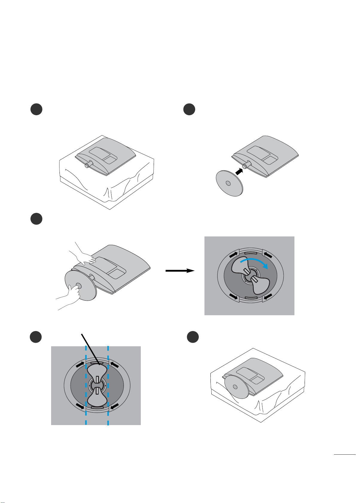
PREPARATION
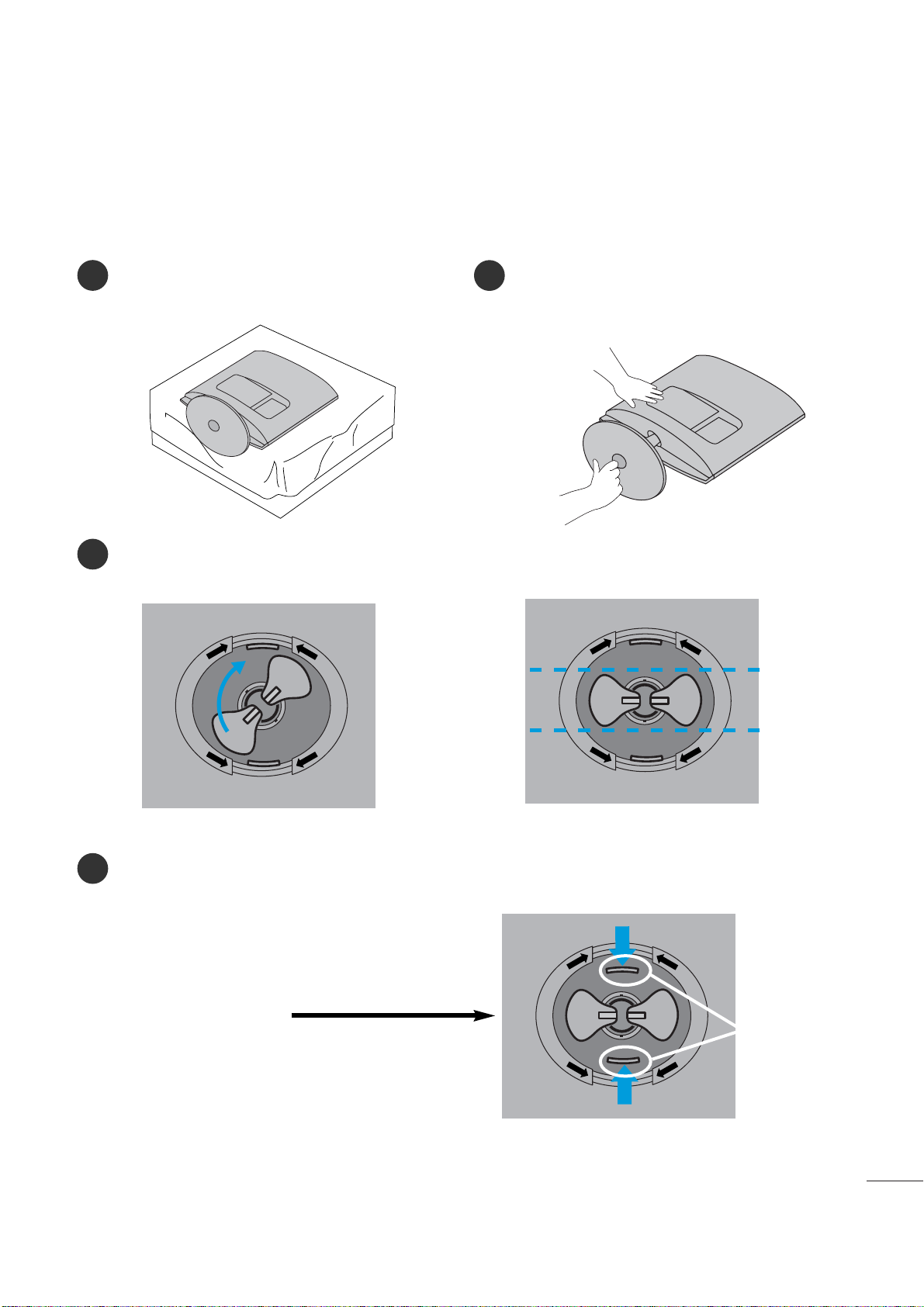
STAND INSTALLATION
■
The image shown may be somewhat different from your set.
1
2
3
Carefully place the product screen side down on a
cushioned surface that will protect product and
screen from damage.
Insert the
sta nd ba se
into the product
Turn the Stand Base Lock through 90° to fix the Stand Base to the Stand Body.
Bas e Lo c k
<Lo cke d>
4 5
O
P
E
N
O
P
E
N
O
P
E
N
O
P
E
N
<M226 2D /M 23 62 D>
4
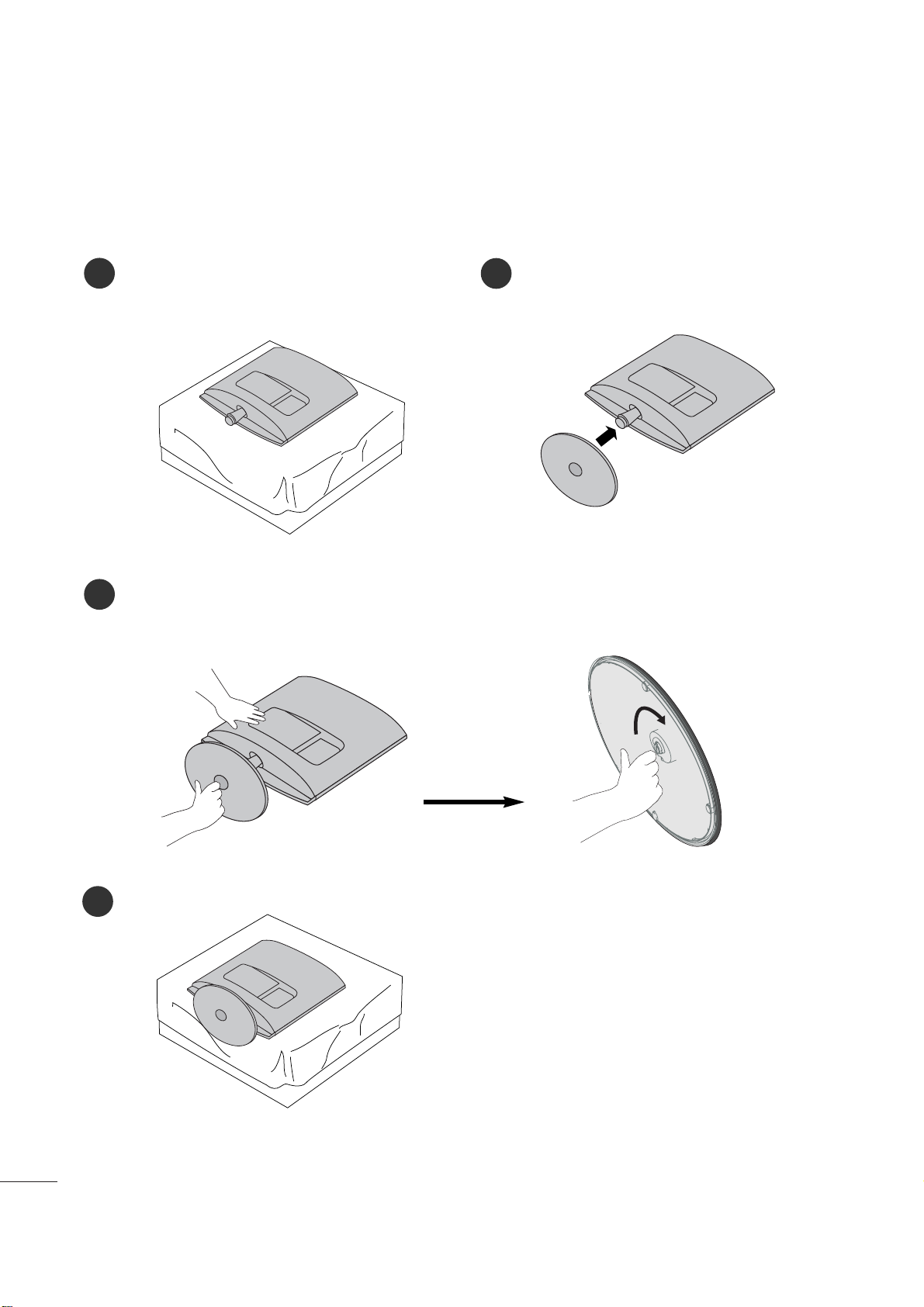
PREPARATION
STAND INSTALLATION
■
The image shown may be somewhat different from your set.
1
2
3
Carefully place the product screen side down on a
cushioned surface that will protect product and
screen from damage.
Insert the
sta nd ba se
into the product
Attach the monitor to the Stand Base by turning the screw to the right.
*Turn the screw by using the screw handle
4
<M27 62 D>
5
PREPARATION
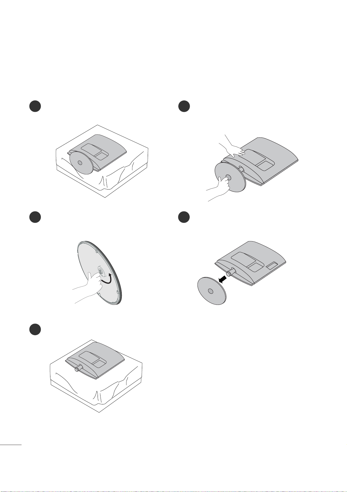
DETACHING STAND
■
The image shown may be somewhat different from your monitor.
1
2
3
4
Place the set screen side down on a cushion or
soft cloth.
Detach the monitor to the Stand Base by turning the screw to the left.
Turn the Stand Base Lock through 90
° to separate the Stand Base from the Stand Body.
Pushing Latch inside, Take the stand base from stand body.
O
P
E
N
O
P
E
N
O
P
E
N
O
P
E
N
O
P
E
N
O
P
E
N
La t ch
<M226 2D /M 23 62 D>
6
PREPARATION
DETACHING STAND
■
The image shown may be somewhat different from your monitor.
1
2
3
5
Place the set screen side down on a cushion or
soft cloth.
Detach the monitor to the Stand Base by
turning the screw to the left.
Turn the screw by using the screw handle.
4
Pull the stand base.
<M27 62 D>

7
PREPARATION
<M27 62 D>
DETACHING STAND BODY
1. Remove the screw 4 point.
2. Pull the stand body.
1. Remove the screw 2 point.
2. Pull the stand body.
■
The image shown may be somewhat different from your set.
■
Remove the Stand Body in the same way as the following when using it as a Wall Hook.
<M226 2D /M 23 62 D>
8
PREPARATION
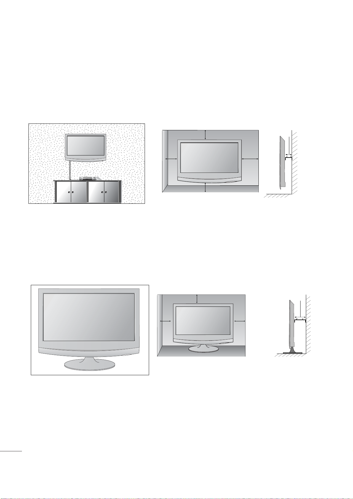
DESKTOP PEDESTAL INSTALLATION
For proper ventilation, allow a clearance of 4 inches on each side and from the wall.
WALL MOUNT: HORIZONTAL INSTALLATION
For proper ventilation, allow a clearance of 4 inches on each side and from the wall. Follow the instructions
included with the wall mount.
4 inches
4 inches
4 inches
4 inches
4 inches
4 inches
4 inches 4 inches
4 inches
9
PREPARATION
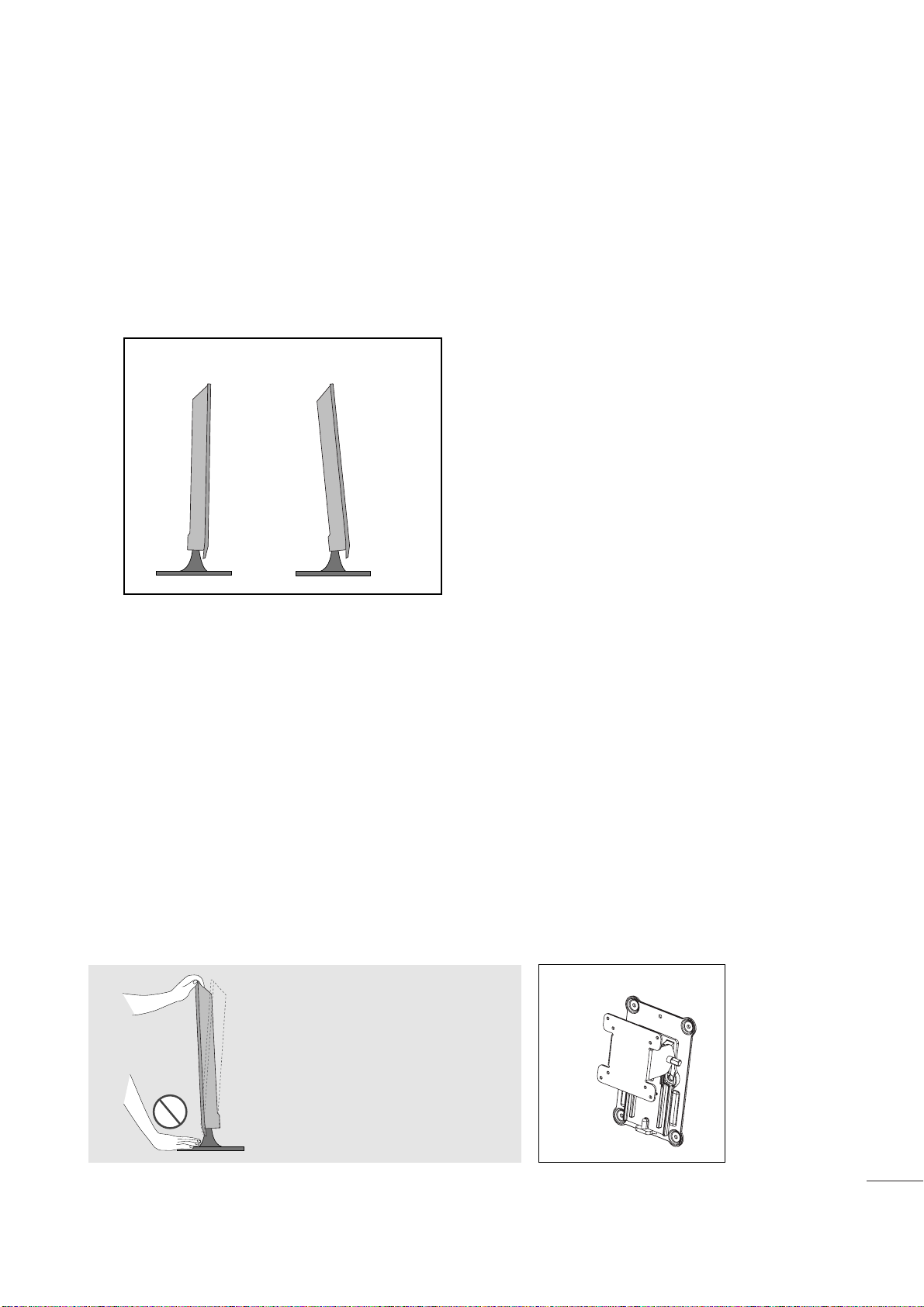
POSITIONING YOUR DISPLAY
■
The image shown may be somewhat different from your set.
Adjust the position of the panel in various ways for maximum comfort.
• Til t ran ge
LOCATION
Position your set so that no bright light or sunlight falls directly onto the screen. Care should be taken not to expose
the set to any unnecessary vibration, moisture, dust or heat. Also, ensure that the set is placed in a position to allow a
free flow of air. Do not cover the ventilation openings on the back cover.
If you intend to mount the set to a wall, attach the wall mounting interface (optional parts) to the back of the set.
When you install the set using the wall mounting interface (optional parts), attach it carefully so it will not drop.
- Be sure to use screws and a wall mount that meet VESA standards.
- Using screws longer than those recommended might damage the product.
- Using screws that do not meet VESA standards might either damage the product or result in it coming away from the
wall. We will not be held responsible for any damage resulting from failure to follow these instructions.
< Screw Mounting Interface Dimension >
M22 6 2D/ M23 62D
: 100mm x 100mm hole spacing
M27 62D
: 200mm x 100mm hole spacing
* Wall mount interface(LG) : RW120
War nin g:
When adjusting the angle of the
screen, do not put your finger(s)in
between the head of the monitor
and the stand body. You can hurt
your finger(s).
RW120
-5
°
15
°
10
PREPARATION
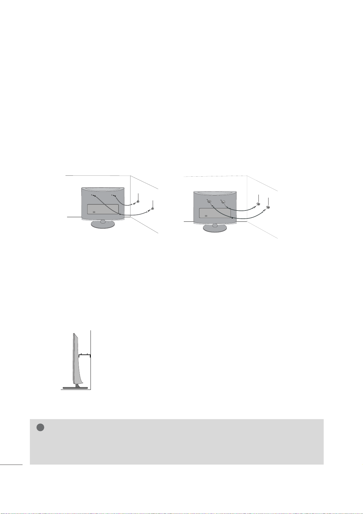
SECURING THE SET TO THE WALL TO PREVENT FALLING
WHEN THE SET IS USED ON A STAND
We recommend that you set up the set close to a wall so it cannot fall over if pushed backwards.
Additionally, we recommend that the set be attached to a wall so it cannot be pulled in a forward direction,
potentially causing injury or damaging the product.
Caution: Please make sure that children don’t climb on or hang from the set.
■
Insert the eye-bolts (or set brackets and bolts) to tighten the product to the wall as shown in the picture.
*If your product has the bolts in the eye-bolts position before inserting the eye-bolts, loosen the bolts.
* Insert the eye-bolts or set brackets/bolts and tighten them securely in the upper holes.
Secure the wall brackets with the bolts (sold separately) to the wall. Match the height of the bracket that is
mounted on the wall to the holes in the product.
Ensure the eye-bolts or brackets are tightened securely.
■
Use a sturdy rope or cord (sold separately) to tie the product. It is
safer to tie the rope so it becomes horizontal between the wall and the
product.
■
Image shown may differ from your set.
G
When moving the set, undo the cords first.
G
Use a platform or cabinet strong enough and large enough to support the size and weight of the set.
G
To use the set safely make sure that the height of the bracket on the wall and the one on the set are the same.
NOTE
!
11
PREPARATION
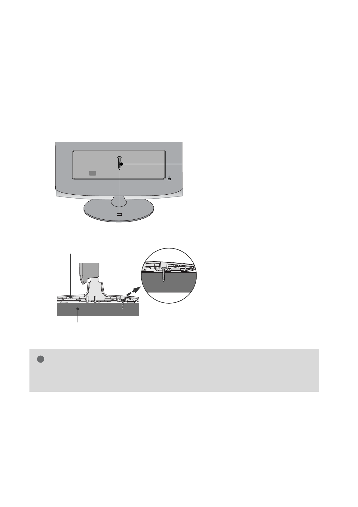
ATTACHING THE TV TO A DESK (Only M2762D)
The TV must be attached to desk so it cannot be pulled in a forward/backward direction,potentially causing
injury or damaging the product.Use only an attached screw.
■
Image shown may differ from your set.
WARNING
!
G To prevent TV from falling over,the TV should be securely attached to the floor/wall per installation
instructions. Tipping,shaking, or rocking the machine may cause injury.
1-Screw
(provided as parts of the product)
Stand
Desk
12
PREPARATION
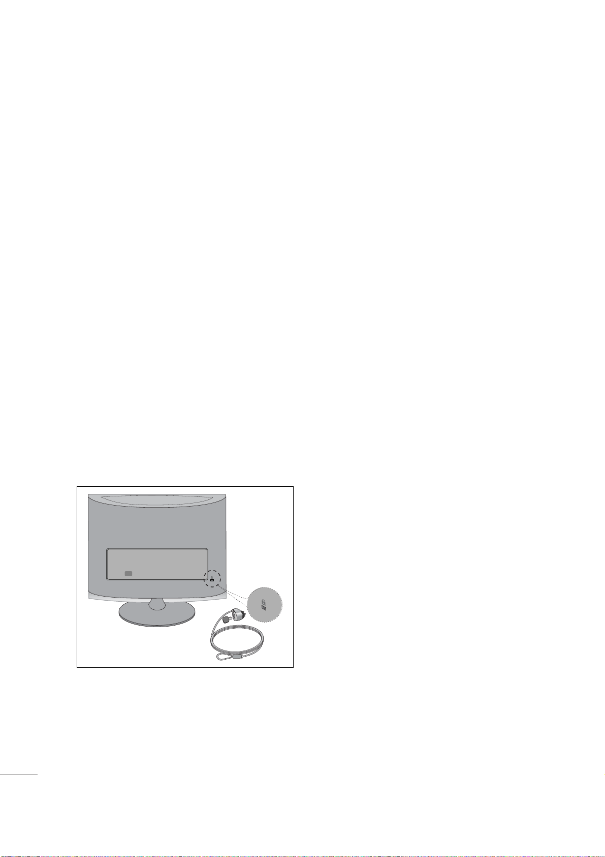
KENSINGTON SECURITY SYSTEM
- The product is equipped with a Kensington Security System connector on the back panel. Connect the
Kensington Security System cable as shown below.
- For detailed installation and use of the Kensington Security System, refer to the user’s guide provided with the
Kensington Security System.
For further information, contact
http :// w ww. kens ing ton. com
, the internet homepage of the Kensington
company. Kensington sells security systems for expensive electronic equipment such as notebook PCs and
LCD projectors.
NOTE
- The Kensington Security System is an optional accessory available at most electronics stores.
NOTES
a. If the product feels cold to the touch, there may be a small “flicker” when it is turned on.
This is normal, there is nothing wrong with product.
b. Some minute dot defects may be visible on the screen, appearing as tiny red, green, or blue spots. However,
they have no adverse effect on the monitor's performance.
c. Avoid touching the LCD screen or holding your finger(s) against it for long periods of time.
ANTENNA/
CABLE IN
ANTENNA/
CABLE IN
13
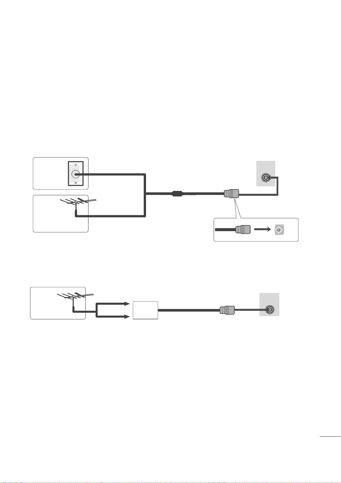
PREPARATION
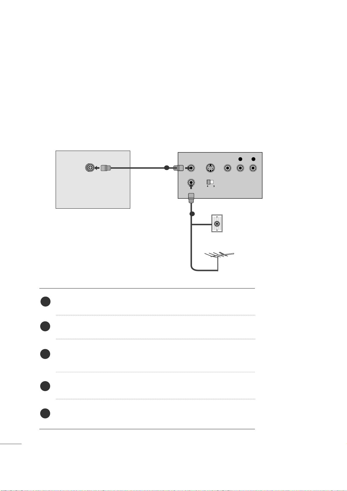
■
For optimum picture quality, adjust antenna direction.
■
An antenna cable and converter are not supplied.
■
To prevent equipment damage, never plug in any power cords until you have finished connecting all equipment.
Multi-family Dwellings/Apartments
(Connect to wall antenna socket)
Single-family Dwellings /Houses
(Connect to wall jack for outdoor antenna)
Outdoor
Antenna
(VHF, UHF)
Wall
Antenna
Socket
RF Coaxial Wire (75 ohm)
ANTENNA CONNECTION
Antenna
UHF
VHF
■
In poor signal areas, to get better picture quality, install a signal amplifier to the antenna as shown above.
■
If signal needs to be split for two TVs, use an antenna signal splitter for connection.
Signal
Amplifier
14
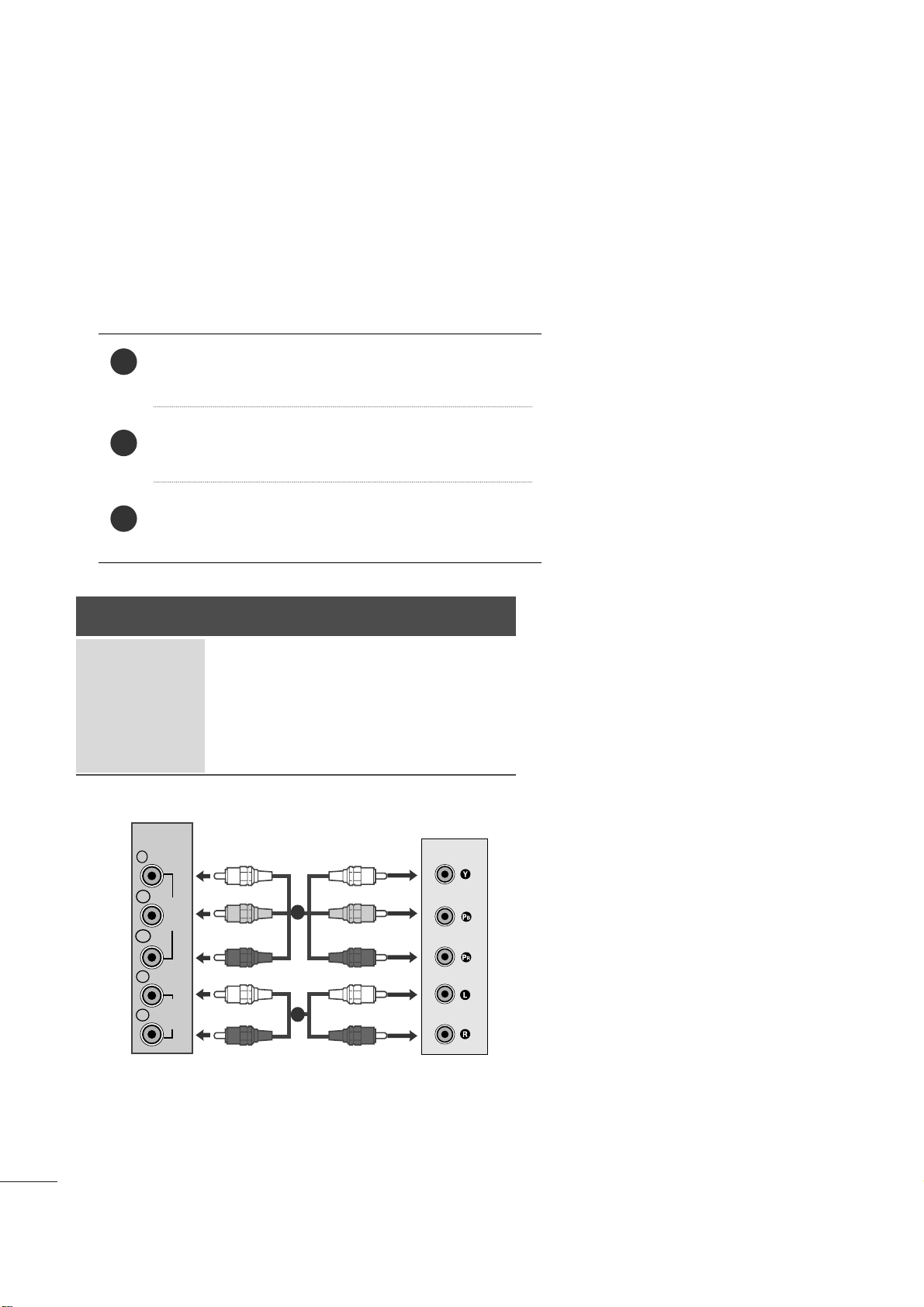
EXTERNAL EQUIPMENT SETUP
Connect the SET-TOP outputs to the
COMPO NENT IN
VID EO
sockets (Y P
B PR) on the set.
Connect the audio cable from the SET-TOP to
CO M PO-
NEN T IN AUD IO
sockets of the set.
Press the
INP UT
button to select
Com pon ent .
2
3
1
HD RECEIVER SETUP
■
To prevent the equipment damage, never plug in any power cords until you have finished connecting all equipment.
■
The image shown may be somewhat different from your set.
When connecting with a component cable
Signal
480i
480p
576p
720p/1080i
1080p
Component
Yes
Yes
No
Yes
Yes
HDMI
No
Yes
Yes
Yes
Yes
VIDEO
COMPONENT
IN
AUDIO
Y
P
B
P
R
L
R
1
2
15
EXTERNAL EQUIPMENT SETUP
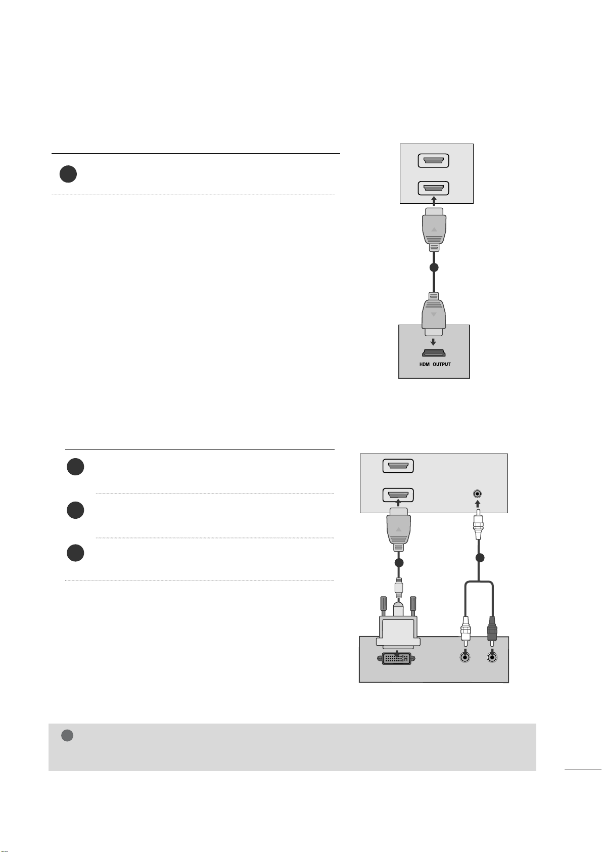
When connecting with a HDMI
Connect the HDMI output of the digital set-top box to the
HDM I IN
jack on the set.
1
Connect the digital set-top box to
HDM I IN
jack on
the set.
Connect the audio output of the digital set-top box to
the
AUDI O I N (RGB /DVI )
jack on the set.
Turn on the digital set-top box. (Refer to the owner’s
manual for the digital set-top box.
)
2
3
1
When connecting with a HDMI to DVI cable
HDMI IN
1
2
1
DVI OUTPUT
AUDIO
R
L
AUDIO
IN
(R
G
B/DV
I)
HDMI IN
1
2
1
2
NOTE
!
G HDMI Input does not support PC mode. If it is connected PC, the screen may not display properly.
16
EXTERNAL EQUIPMENT SETUP
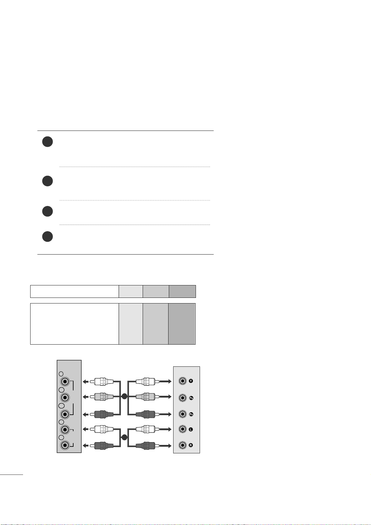
DVD SETUP
When connecting with a component cable
Component Input ports
To get better picture quality, connect a DVD player to the component input ports as shown below.
Component ports on the set
YPB PR
Video output ports
on DVD player
Y
Y
Y
Y
P
B
B-Y
Cb
Pb
P
R
R-Y
Cr
Pr
Connect the video output sockets (Y PB PR) of the DVD
to the
COMP ONE NT IN VI DEO
sockets (Y P
B PR) of
the set.
Connect the audio cable from the DVD to
CO M PO-
NEN T IN AU DIO
sockets of the set.
Press the
INP UT
button to select
Com p one n t
.
Press the
PL AY
button on the DVD.
The DVD playback picture appears on the screen.
2
3
4
1
VIDEO
COMPONENT
IN
AUDIO
Y
P
B
P
R
L
R
1
2
17
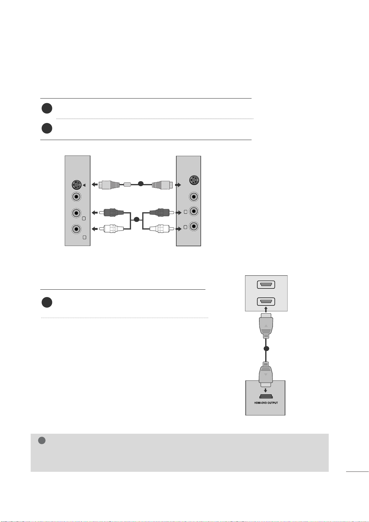
EXTERNAL EQUIPMENT SETUP
When connecting HDMI cable
Connect the HDMI output of the DVD to the
HDM I IN
jack on the set.
1
G
HDMI supports video and audio. You do not need to connect a sperate audio cable.
G
If the DVD player does not support Auto HDMI, you need to set the DVD output resolution appropriately.
NOTE
!
HDMI IN
1
2
1
When connecting S-Video
Connect the S-Video output of the DVD to the S-Video in put on the set.
Connect the audio output of the DVD to the AUDIO in put on the set.
1
2
VIDEO AUDIO
(MONO)
S-VIDEO
L
R
AV-IN
VIDEO
S-VIDEO
L
R
1
2
18
EXTERNAL EQUIPMENT SETUP
VCR SETUP
■
To avoid picture noise (interference), leave an adequate distance between the VCR and the set.
■
If a user uses 4:3 picture format for a long time, an afterimage may remain on the sides of the screen for a
short time.
OUTPUT
SWITCH
ANT IN
R
S-VIDEO VIDEO
ANT OUT
L
ANTENNA/
CABLE IN
Wall Jack
Antenna
1
2
When connecting with an antenna
Connect the RF out socket of the VCR to the antenna socket of the set.
Connect the antenna cable to the RF aerial in socket of the VCR.
Store the VCR channel on a desired channel number using the ‘Manual channel
tuning’ section.
Select the Channel number where the VCR channel is stored.
Press the
PLA Y
button on the VCR.
1
2
3
4
5
19
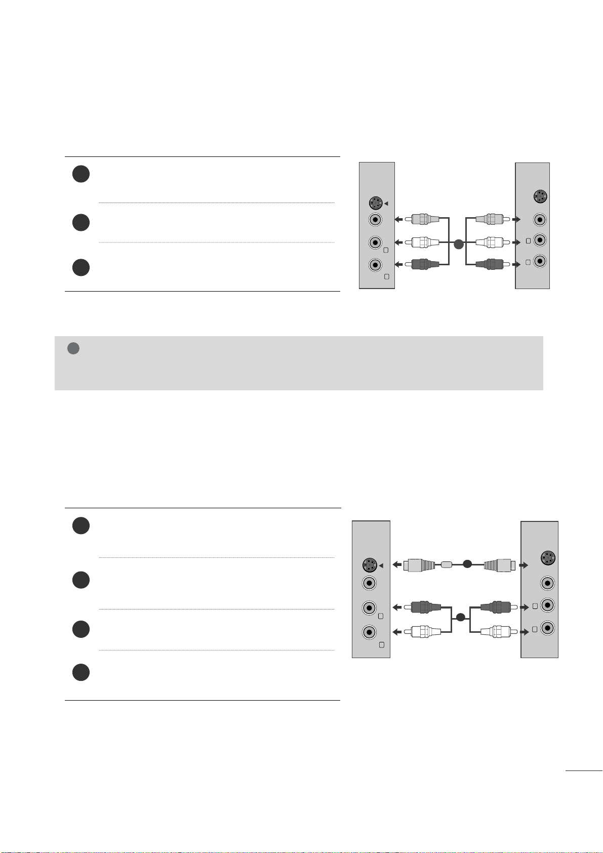
EXTERNAL EQUIPMENT SETUP
When connecting with a RCA cable
Connect the audio/video out sockets of the VCR to
AUDIO/VIDEO in sockets of the set.
Press the INPUT button to select AV.
Press the PLAY button on the VCR.
The VCR playback picture appears on the screen.
2
3
1
When connecting with an S-Video cable
Connect the S-Video socket of the VCR to the SVIDEO socket of the set.
Connect the audio cable from the S-VIDEO of the VCR
to the AUDIO sockets of the set.
Press the INPUT button to select AV.
Press the PLAY button on the VCR.
The VCR playback picture appears on the screen.
2
3
4
1
NOTE
!
G
If you have a mono VCR, connect the audio cable from the VCR to the AUDIO L/MONO jack of the set.
VIDEO AUDIO
(MONO)
S-VIDEO
L
R
AV-IN
VIDEO
S-VIDEO
L
R
VIDEO AUDIO
(MONO)
S-VIDEO
L
R
AV-IN
VIDEO
S-VIDEO
L
R
1
2
1
20
EXTERNAL EQUIPMENT SETUP
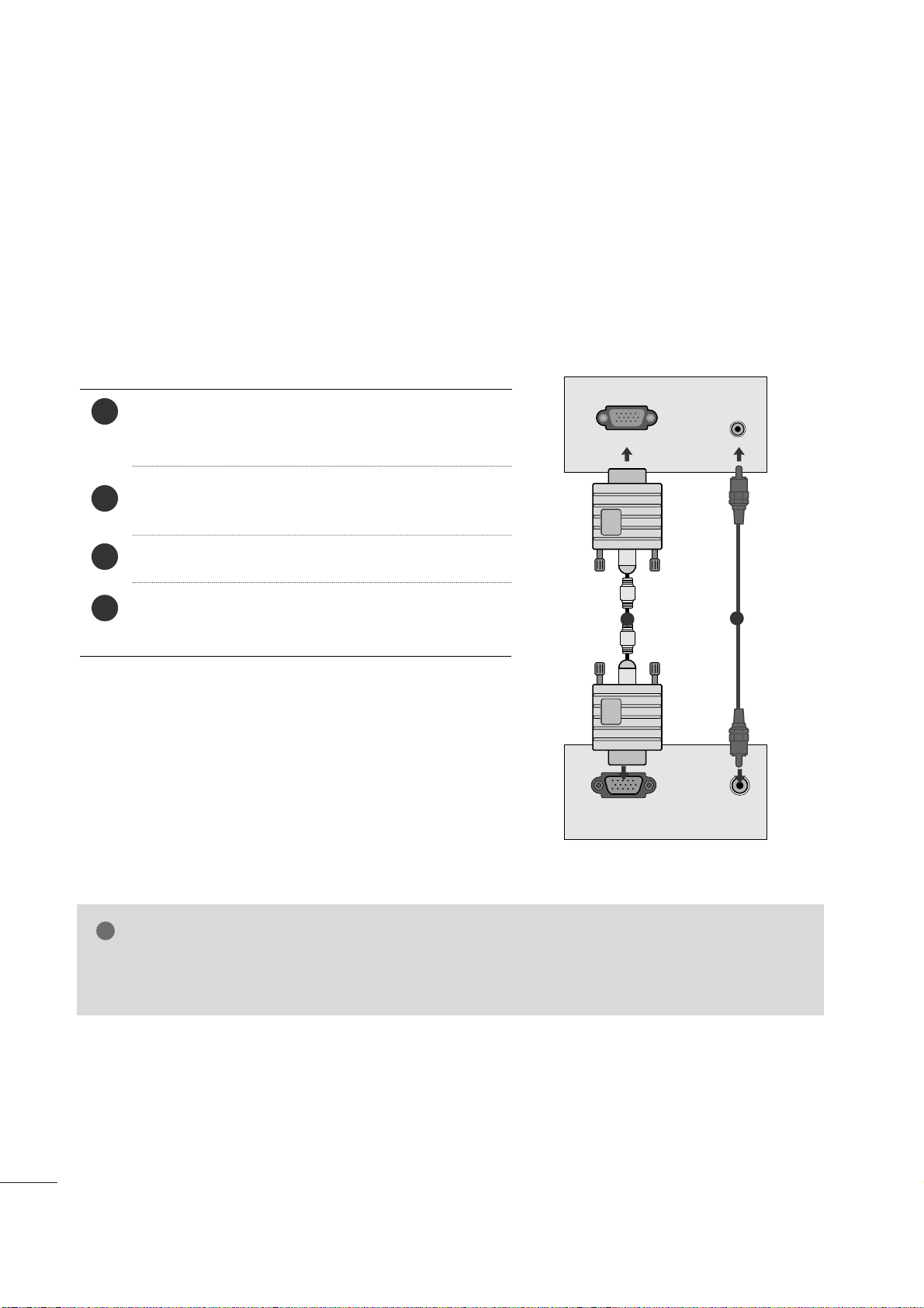
PC SETUP
This product provides Plug and Play capability, meaning that the PC adjusts automatically to the set's settings.
When connecting with a D-sub 15 pin cable
4
Connect the signal cable from the monitor output socket
of the PERSONAL COMPUTER to the PC input socket of
the set.
Connect the audio cable from the PC to the
AUD IO I N
(RG B/D VI)
sockets of the set.
Press the INPUT button to select
RG B
.
Switch on the PC, and the PC screen appears on the set.
The set can be operated as a PC monitor.
2
3
1
RGB OUTPUT
AUDIO
AUDIO IN
(RGB/DVI)
RGB IN (PC)
1
2
NOTE
!
G
User must use shielded signal interface cables (D sub 15 pin cable, DVI cable) with ferrite cores to maintain standard compliance for the product.
 Loading...