

LG M197WAP-PM Owner's Manual

ENGLISH
OWNER’S MANUAL
MONITOR TV
Please read this manual carefully before operating
your set and retain it for future reference.
MONITOR TV MODELS
M197WAP
M227WAP
M237WAP
M2062A
M2262A
M2362A
M2762A
www.lg.com

CONTENTS
CONTENTS
PREPARATION
SIDE PANEL CONTROLS
<M197WAP/M227WAP/M237WAP>
FRONT PANEL CONTROLS
<M2062A/M2262A/M2362A/M2762A>.........5
BACK PANEL INFORMATION
<M197WAP/M227WAP/M237WAP>
<M2062A/M2262A/M2362A/M2762A>.........7
STAND INSTALLATION
<M197WAP/M227WAP>
<M237WAP>
<M2062A/M2262A/M2362A>
<M2762A>
DETACHING STAND
<M197WAP/M227WAP>
<M237WAP>
<M2062A/M2262A/M2362A>
<M2762A>
DETACHING STAND BODY
(M2062A/M2262A/M2362A/M2762A)
WALL MOUNT: HORIZONTAL INSTALLATION
DESKTOP PEDESTAL INSTALLATION
SWIVEL STAND(Only M2762A)
POSITIONING YOUR DISPLAY
LOCATION
SECURING THE SET TO THE WALL TO
PREVENT FALLING WHEN THE SET IS USED
ON A STAND (Only M2762A)
ATTACHING THE TV TO A DESK
(Only M2762A)
KENSINGTON SECURITY SYSTEM
................................................9
..................................................11
..............................................13
..................................................15
........................................................20
..................................................22
..............................8
.....................10
............................12
.....................14
.......................19
.......................19
............................21
............4
............6
...............16
..17
...........18
...............23
VCR SETUP
Connecting with a RF cable
Connecting with a RCA cable
OTHER A/V SOURCE SETUP
PC SETUP
When connecting with a D-sub 15 pin cable
BACK COVER FOR WIRE ARRANGEMENT
SUPPORTED DISPALY RESOLUTION
.......................29
.....................29
.........................30
...31
..32
...........33
WATCHING TV / PROGRAMME
CONTROL
REMOTE CONTROL KEY FUNCTIONS ..........34
TURNING ON THE SET
INSTALLATION GUIDE
PROGRAMME SELECTION
VOLUME ADJUSTMENT
ON SCREEN MENUS SELECTION AND
ADJUSTMENT
AUTO PROGRAMME TUNING
MANUAL PROGRAMME TUNING
FINE TUNING
ASSIGNING A STATION NAME
PROGRAMME EDIT
FAVOURITE PROGRAMME
SELECTING THE PROGRAMME LIST
..................................................37
...................................................40
...................................36
.....................................36
.............................36
..................................36
........................38
...................39
.......................41
.........................................42
.............................43
............44
PICTURE CONTROL
PICTURE SIZE (ASPECT RATIO) CONTROL ...45
EXTERNAL EQUIPMENT SETUP
ANTENNA CONNECTION ................................24
HD RECEIVER SETUP
When connecting with a component cable
Connecting a set-top box with a HDMI cable
DVD SETUP
Connecting with a component cable
Connecting with a HDMI cable
...................28
...25
..26
..........27
PRESET PICTURE SETTINGS
MANUAL PICTURE ADJUSTMENT
PICTURE IMPROVEMENT TECHNOLOGY
PICTURE RESET
SCREEN SETUP
AUTO CONFIGURE
(RGB [PC] mode only)................................51
MANUAL CONFIGURE
(Adjustment for screen Position)
.............................................50
........................46
.................47
....48
................52
2

INITIALIZING
(Reset to original factory settings) ..............53
SELECTING RESOLUTION .......................54
SOUND CONTROL
PRESET SOUND SETTINGS
- SOUND MODE ........................................55
SOUND SETTING ADJUSTMENT
- USER MODE ...........................................56
AUTO VOLUME LEVELER ...............................57
BALANCE ..........................................................58
AUDIO RESET ..................................................59
I/II
STEREO / DUAL RECEPTION ........................60
NICAM RECEPTION ........................................61
SPEAKER SOUND OUTPUT SELECTION .....61
TELETEXT
SWITCH ON/OFF .............................................72
SIMPLE TEXT ...................................................72
SWITCH ON/OFF .............................................73
FASTEXT ..........................................................73
SPECIAL TELETEXT FUNCTIONS ..................74
APPENDIX
TROUBLESHOOTING ......................................75
MAINTENANCE ................................................77
PRODUCT SPECIFICATIONS
M197WAP ...................................................78
M227WAP ...................................................79
M237WAP ...................................................80
M2062A .......................................................81
M2262A .......................................................82
M2362A .......................................................83
M2762A .......................................................84
CONTENTS
TIME SETTING
CLOCK SETUP .................................................62
AUTO ON/OFF TIMER SETTING ....................63
SLEEP TIMER SETTING ..................................64
AUTO SLEEP ....................................................65
OPTION SETTING
ON-SCREEN MENU LANGUAGE SELECTION ...66
KEY LOCK ........................................................67
DDC-CI(Only RGB) ...........................................68
POWER INDICATOR ........................................69
MODE SETTING ...............................................70
FACTORY RESET ............................................71
3
PREPARATION
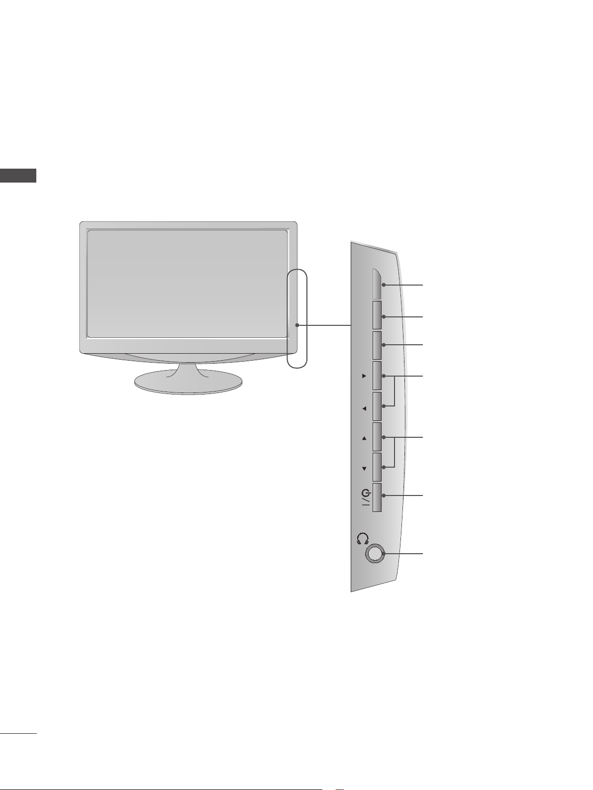
SIDE PANEL CONTROLS
■ This is a simplified representation of the side panel. The image shown may be somewhat different
from your set.
PREPARATION
<M197WAP/M227WAP/M237WAP>
INPUT
INPUT Button
MENU
MENU Button
OK Button
VOL PROK
VOLUME Buttons
PROGRAMME Buttons
Power Button
Headphone Jack
4
INPUT
MENU
PR
VOL
OK
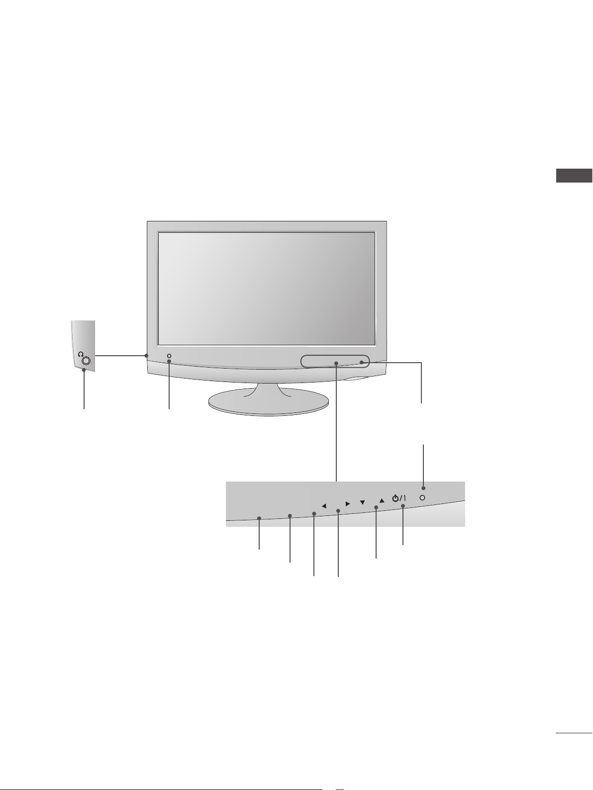
<M2062A/M2262A/M2362A/M2762A>
FRONT PANEL CONTROLS
■ This is a simplified representation of the front panel. The image shown may be somewhat different
from your set.
PREPARATION
Headphone
Jack
IR receiver
(Remote controller
receiver)
INPUT Button
INPUT
MENU
MENU Button
OK Button
OK
VOL
PR
PROGRAMME Button
VOLUME Button
Power Indicator
illuminates blue when the set
is switched on.
POWER Button
5
PREPARATION
<M197WAP/M227WAP/M237WAP>
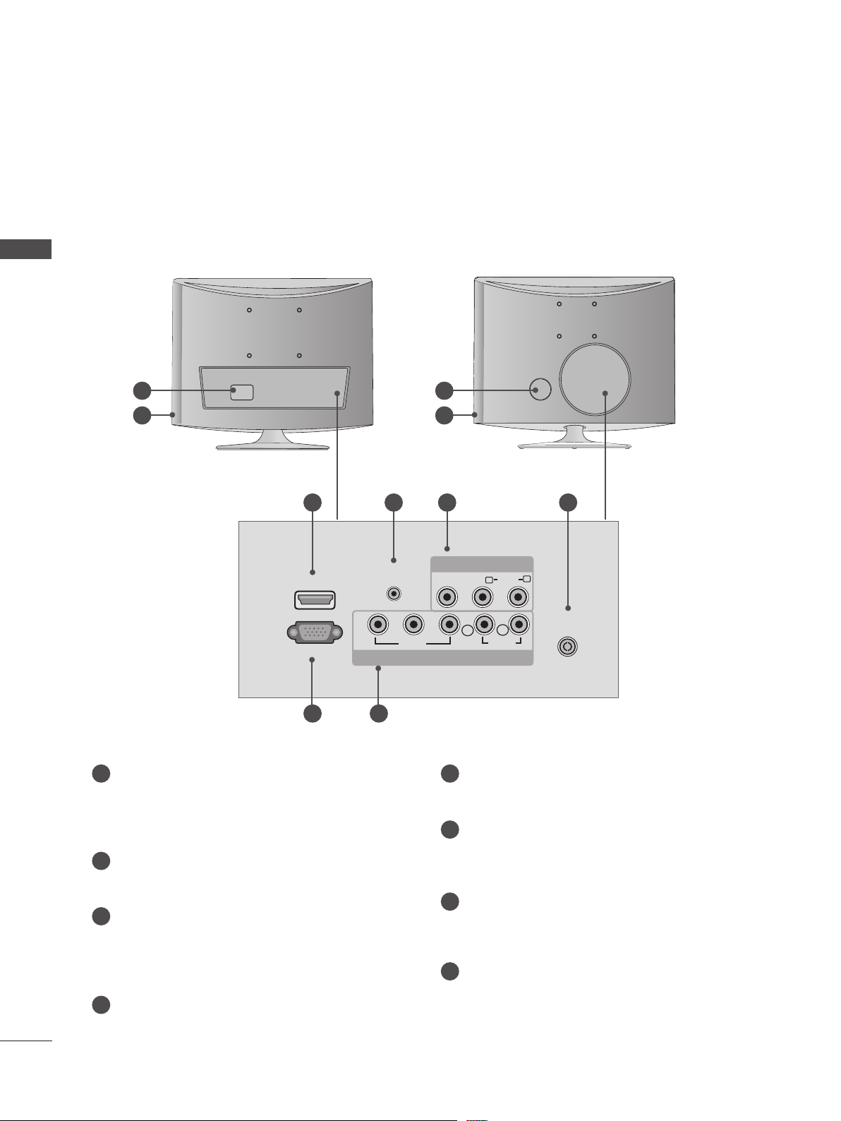
BACK PANEL INFORMATION
■ This is a simplified representation of the back panel. The image shown may be somewhat different
from your set.
PREPARATION
<M197WAP/M227WAP> <M237WAP>
1 1
2 2
3 4 7 8
AV IN
VIDEO AUDIO
(MONO)
R
L
HDMI IN
RGB IN (PC)
Y
AUDIO IN
(RGB)
P
B
VIDEO
P
COMPONENT IN
L
AUDIO
R
ANTENNA/
R
CABLE IN
5 6
1
POWER CORD SOCKET
This set operates on AC power. The voltage is
5
RGB INPUT (PC)
Connect the output from a PC.
indicated on the Specifications page. Never
attempt to operate the set on DC power.
COMPONENT INPUT
6
Connect a component video/audio device to
HEADPHONE AUDIO OUTPUT
2
these jacks.
Connect the audio from a Headphone Jack.
AV(AUDIO/VIDEO) INPUT
HDMI INPUT
3
Connect a HDMI signal to HDMI IN.
7
Connect audio/video output from an external
device to these jacks.
Or DVI (VIDEO) signal to HDMI IN with DVI to
HDMI cable.
ANTENNA / CABLE INPUT
8
Connect over-the-air signals to this jack.
RGB AUDIO INPUT
4
Connect the audio from a PC.
6
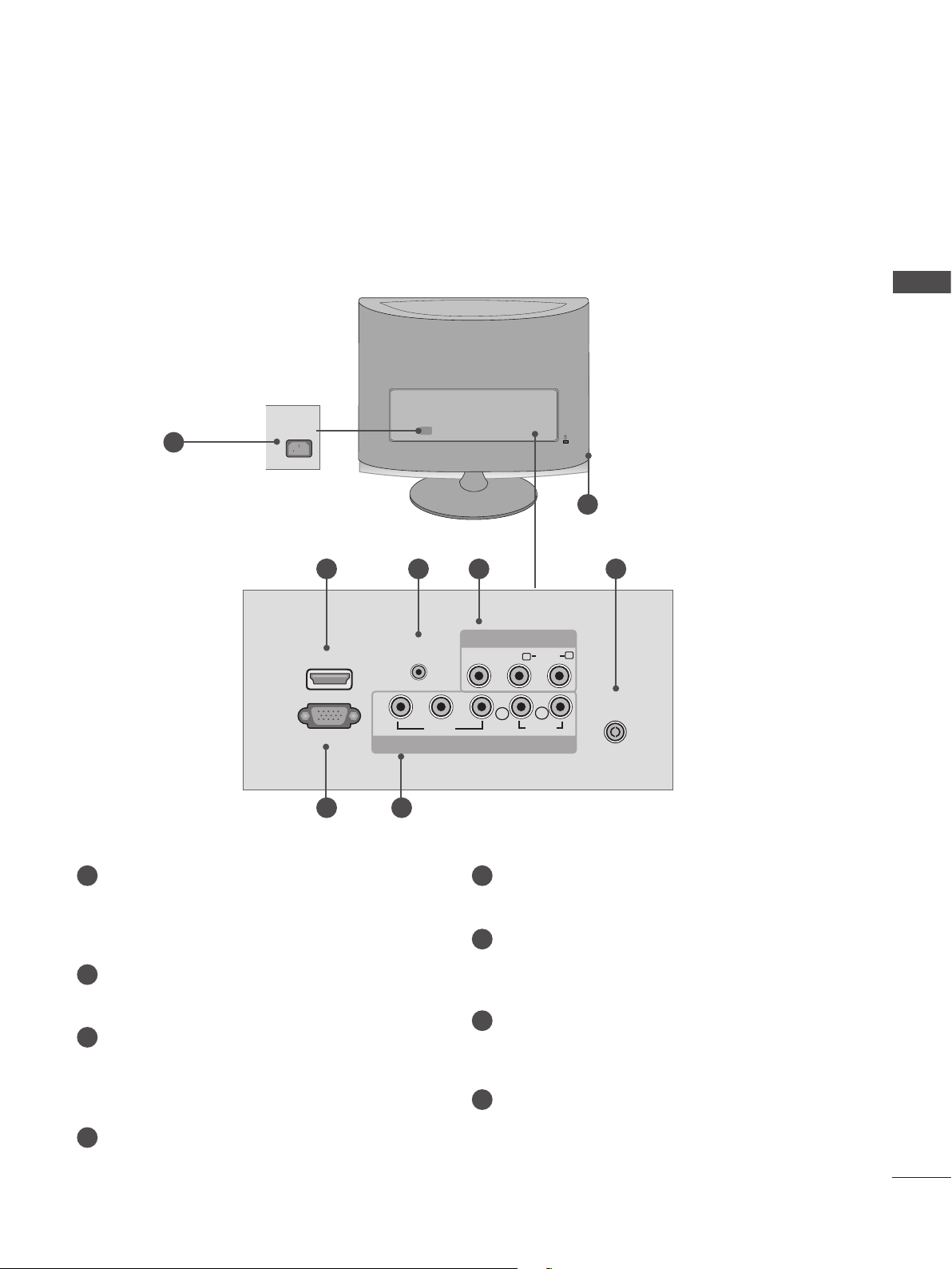
<M2062A/M2262A/M2362A/M2762A>
BACK PANEL INFORMATION
■ This is a simplified representation of the back panel. The image shown may be somewhat different
from your set.
PREPARATION
1
AC IN
3 4 7 8
HDMI IN
RGB IN (PC)
AUDIO IN
Y
5 6
1
POWER CORD SOCKET
This set operates on AC power. The voltage is
indicated on the Specifications page. Never
attempt to operate the set on DC power.
HEADPHONE AUDIO OUTPUT
2
Connect the audio from a Headphone Jack.
HDMI INPUT
3
Connect a HDMI signal to HDMI IN.
Or DVI (VIDEO) signal to HDMI IN with DVI to
HDMI cable.
RGB AUDIO INPUT
4
Connect the audio from a PC.
(RGB)
P
B
VIDEO
AV IN
VIDEO AUDIO
(MONO)
P
R
L
COMPONENT IN
5
RGB INPUT (PC)
Connect the output from a PC.
COMPONENT INPUT
6
Connect a component video/audio device to
these jacks.
AV(AUDIO/VIDEO) INPUT
7
Connect audio/video output from an external
device to these jacks.
ANTENNA / CABLE INPUT
8
Connect over-the-air signals to this jack.
L
R
AUDIO
R
2
ANTENNA/
CABLE IN
7
PREPARATION
INPUT
MENU
VOL CHENTER
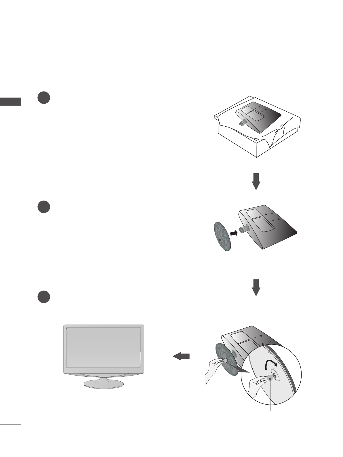
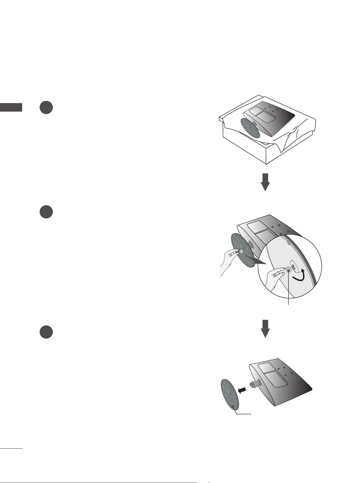
STAND INSTALLATION
■ The image shown may be somewhat different from your set.
Carefully place the product screen side down on a
1
PREPARATION
cushioned surface that will protect product and
screen from damage.
<M197WAP/M227WAP>
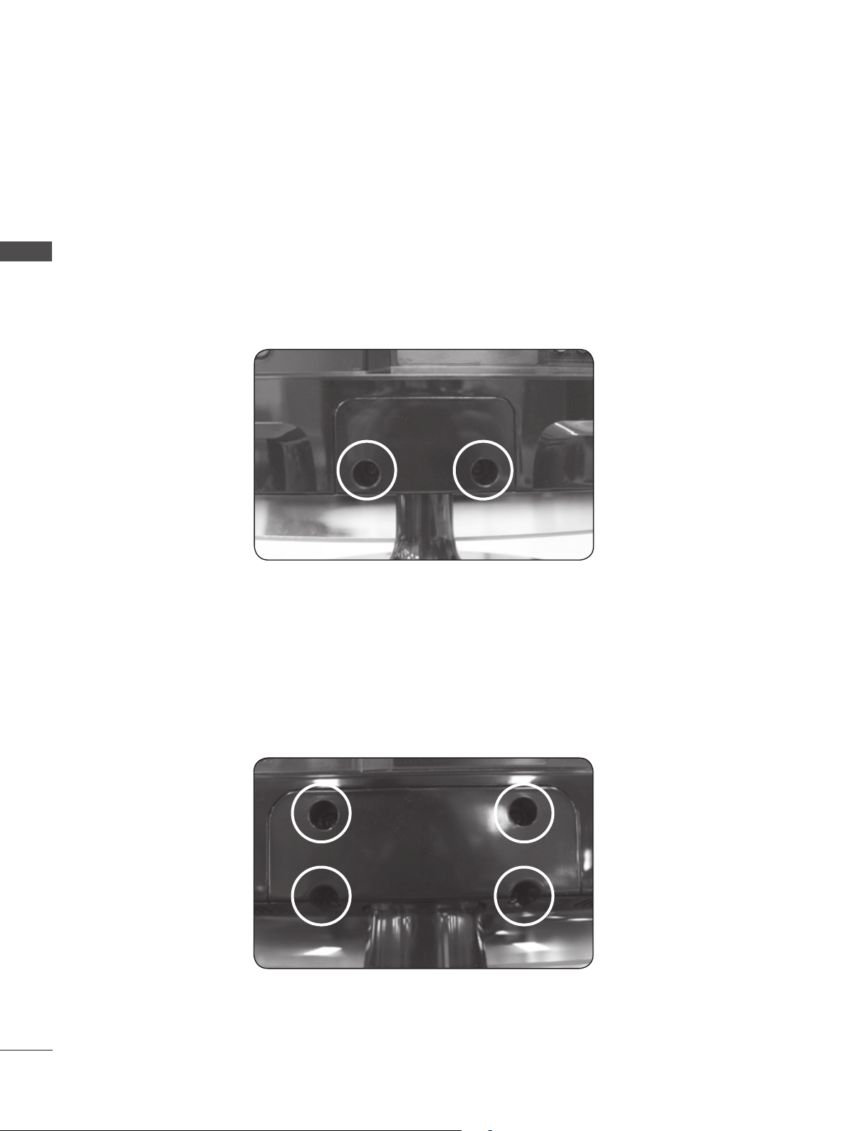
Insert the Stand Base into the product.
2
Use a Coin on the bottom of the stand base and
3
turn the screw clockwise to tighten.
Stand Base
Coin
8
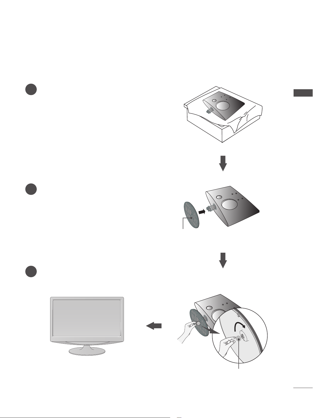
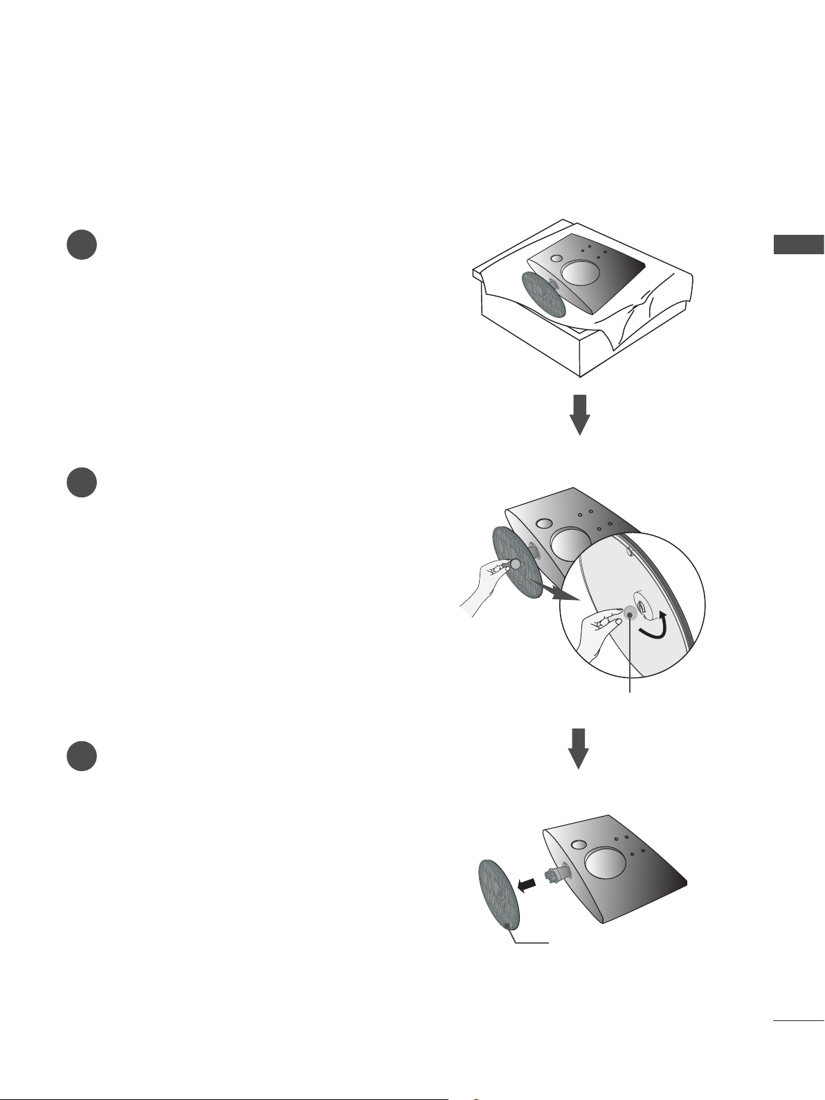
STAND INSTALLATION
INPUT
MENU
VOL CHENTER
■ The image shown may be somewhat different from your set.
Carefully place the product screen side down on a
1
cushioned surface that will protect product and
screen from damage.
Insert the Stand Base into the product.
2
<M237WAP>
PREPARATION
Use a Coin on the bottom of the stand base and
3
turn the screw clockwise to tighten.
Stand Base
Coin
9
PREPARATION
O
P
E
N
O
P
E
N
O
P
E
N
O
P
E
N
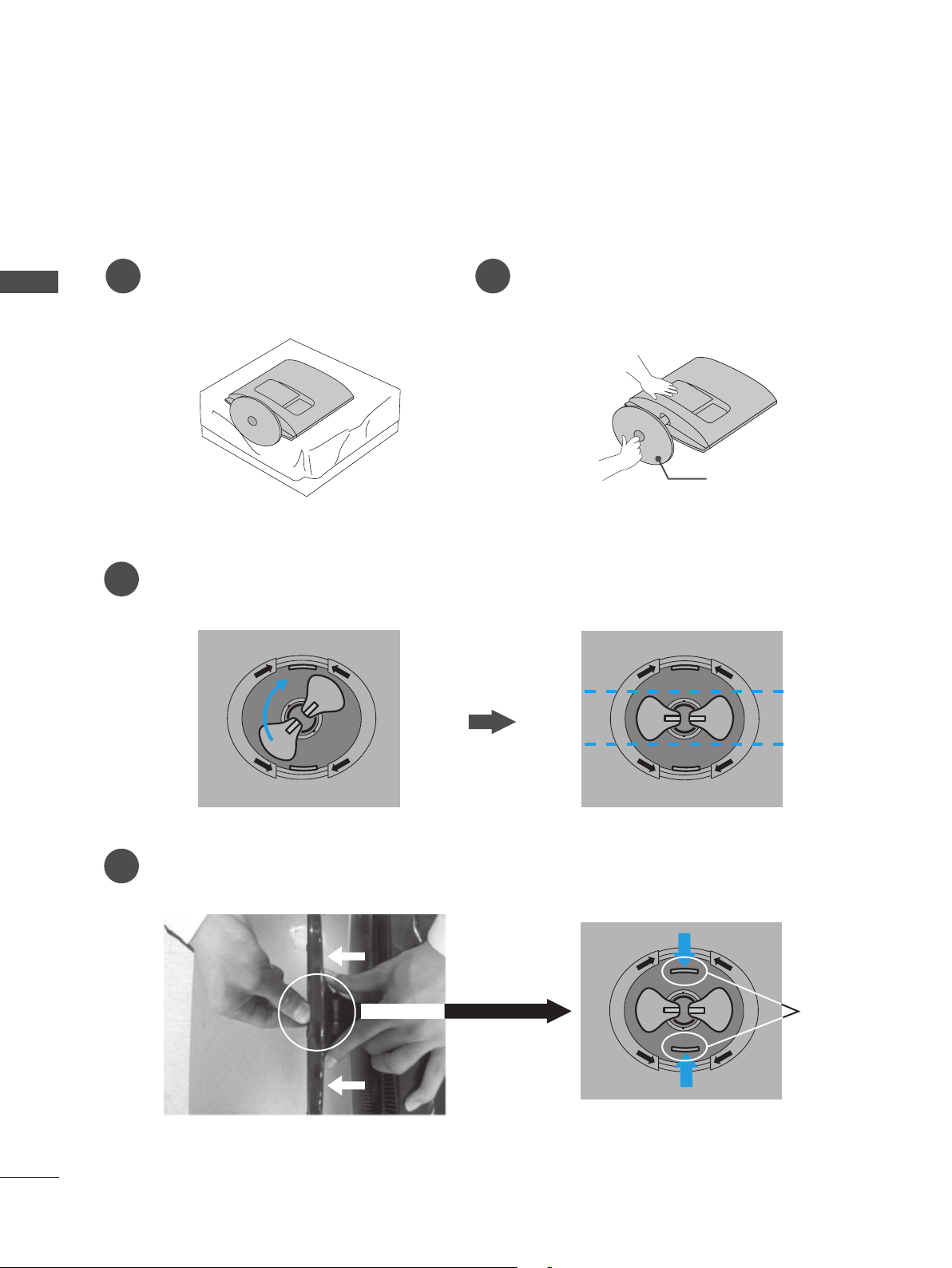
STAND INSTALLATION
■ The image shown may be somewhat different from your set.
<M2062A/M2262A/M2362A>
PREPARATION
Carefully place the product screen side down
1
Insert the Stand Base into the product.
2
on a cushioned surface that will protect
product and screen from damage.
Turn the Stand Base Lock through 90° to fix the stand base to the stand body.
3
O
N
E
P
O
P
E
N
Stand Base
O
N
E
P
O
P
E
N
10
4
Stand Base Lock
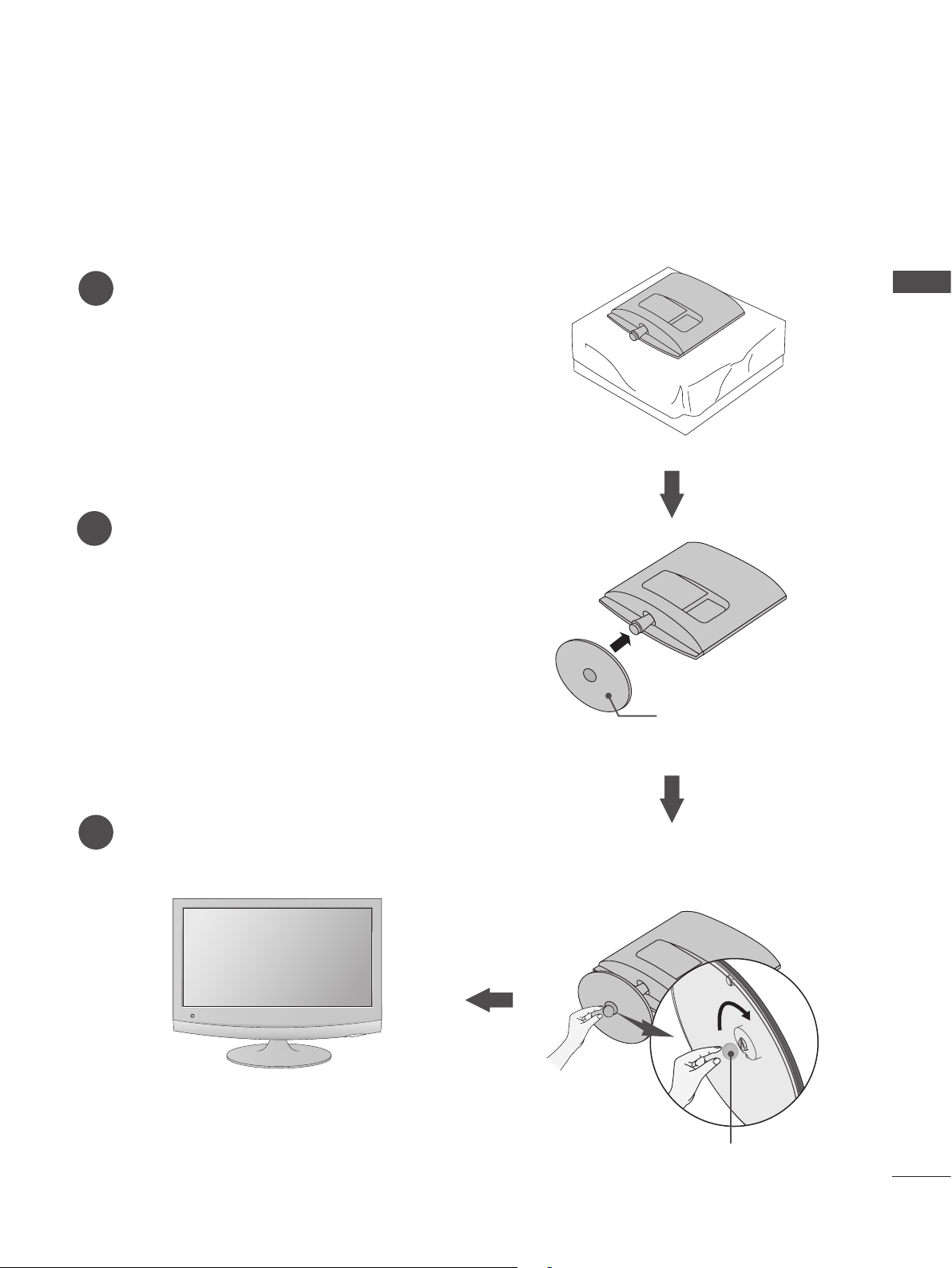
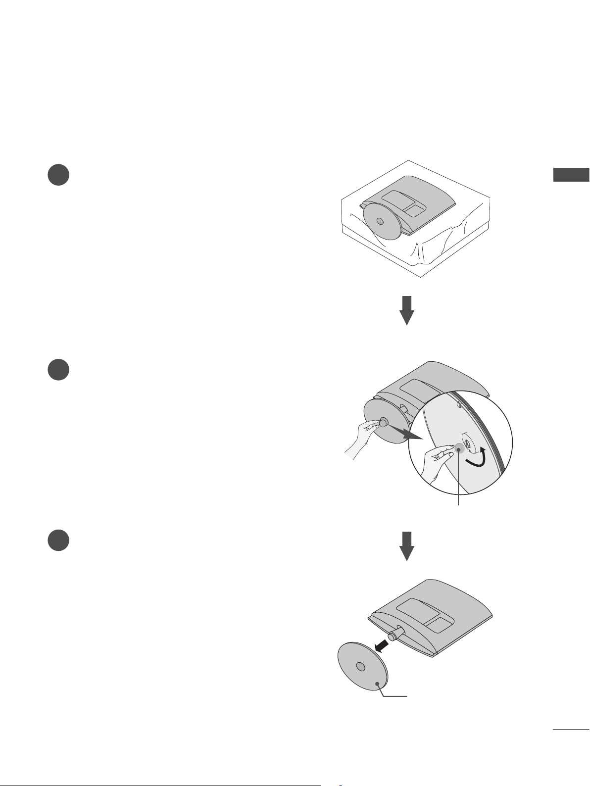
STAND INSTALLATION
■ The image shown may be somewhat different from your set.
Carefully place the product screen side down on a cush-
1
ioned surface that will protect product and screen from
damage.
Insert the Stand Base into the product.
2
<M2762A>
PREPARATION
Use a Coin on the bottom of the stand base and
3
turn the screw clockwise to tighten.
Stand Base
Coin
11
PREPARATION
DETACHING STAND
■ The image shown may be somewhat different from your set.
Place the set screen side down on a cushion or
PREPARATION
1
soft cloth.
Detach the stand base from the set by turning
2
the screw to the left with a Coin.
<M197WAP/M227WAP>
12
Pull the Stand base.
3
Coin
Stand Base
DETACHING STAND
■ The image shown may be somewhat different from your set.
Place the set screen side down on a cushion or
1
soft cloth.
Detach the stand base from the set by turning
2
the screw to the left with a Coin.
<M237WAP>
PREPARATION
Pull the Stand base.
3
Coin
Stand Base
13
PREPARATION
O
P
E
N
O
P
E
N
O
P
E
N
O
P
E
N
O
P
E
N
O
P
E
N
O
P
E
N
O
P
E
N
O
P
E
N
O
P
E
N
O
P
E
N
O
P
E
N
O
P
E
N
O
P
E
N
DETACHING STAND
■ The image shown may be somewhat different from your set.
<M2062A/M2262A/M2362A>
PREPARATION
Place the set screen side down on a
1
cushion or soft cloth.
Detach the monitor to the Stand Base by turn-
2
ing the screw to the left.
Stand Base
Turn the stand base lock through 90° to separate the stand base from the stand body.
3
O
N
E
P
O
P
E
N
N
E
P
O
O
P
E
N
14
Pushing Latch inside, Take the stand base from stand body.
4
O
N
E
P
O
P
E
N
Latch
DETACHING STAND
■ The image shown may be somewhat different from your set.
Place the set screen side down on a cushion or
1
soft cloth.
Detach the stand base from the set by turning
2
the screw to the left with a Coin.
<M2762A>
PREPARATION
Pull the Stand base.
3
Coin
Stand Base
15
PREPARATION
DETACHING STAND BODY (M2062A/M2262A/M2362A/ M2762A)
■ The image shown may be somewhat different from your set.
■ Remove the Stand Body in the same way as the following when using it as a Wall Hook.
PREPARATION
<M2062A/M2262A/M2362A>
1. Remove the screw 2 point.
2. Pull the stand body.
<M2762A>
16
1. Remove the screw 4 point.
2. Pull the stand body.
WALL MOUNT: HORIZONTAL INSTALLATION
■ The image shown may be somewhat different from your set.
For proper ventilation, allow a clearance of 10 cm on each side and from the wall. Detailed installation
instructions are available from your dealer, see the optional Tilt Wall Mounting Bracket Installation and
Setup Guide.
PREPARATION
10 cm
10 cm
10 cm
10 cm
10 cm
If you intend to mount the set to a wall, attach Wall mounting interface (optional parts) to the back of the set.
When you install the set using the wall mounting interface (optional parts), attach it carefully so it will not drop.
1. Be sure to use screws and a wall mount that meet VESA standards.
2. Using screws longer than those recommended might damage the product.
3. Using screws that do not meet VESA standards might either damage the product or result in it coming
away from the wall. We will not be held responsible for any damage resulting from failure to follow these
instructions.
4. VESA compatible only with respect to screw mounting interface dimensions and mounting screw speci-
fications
5. Please use VESA standard as below.
5-1) 784.8 mm (30.9 inch) and under
* Wall Mount Pad Thickness : 2.6 mm
* Screw : Φ 4.0 mm x Pitch 0.7 mm x Length 10 mm
5-2) 787.4 mm (31.0 inch) and above
* Please use VESA standard wall mount pad and screws.
< Screw Mounting Interface Dimension >
Model M237WAP M197WAP
M2762A
M227WAP
M2062A
M2262A
M2362A
VESA ( A x B) 75 x 75 100 x 100 200 x 100
Wall mount
RW120 RW240
bracket(optional)
Wall Mount Pad
17
PREPARATION
INPUT
MENU
VOL CHENTER
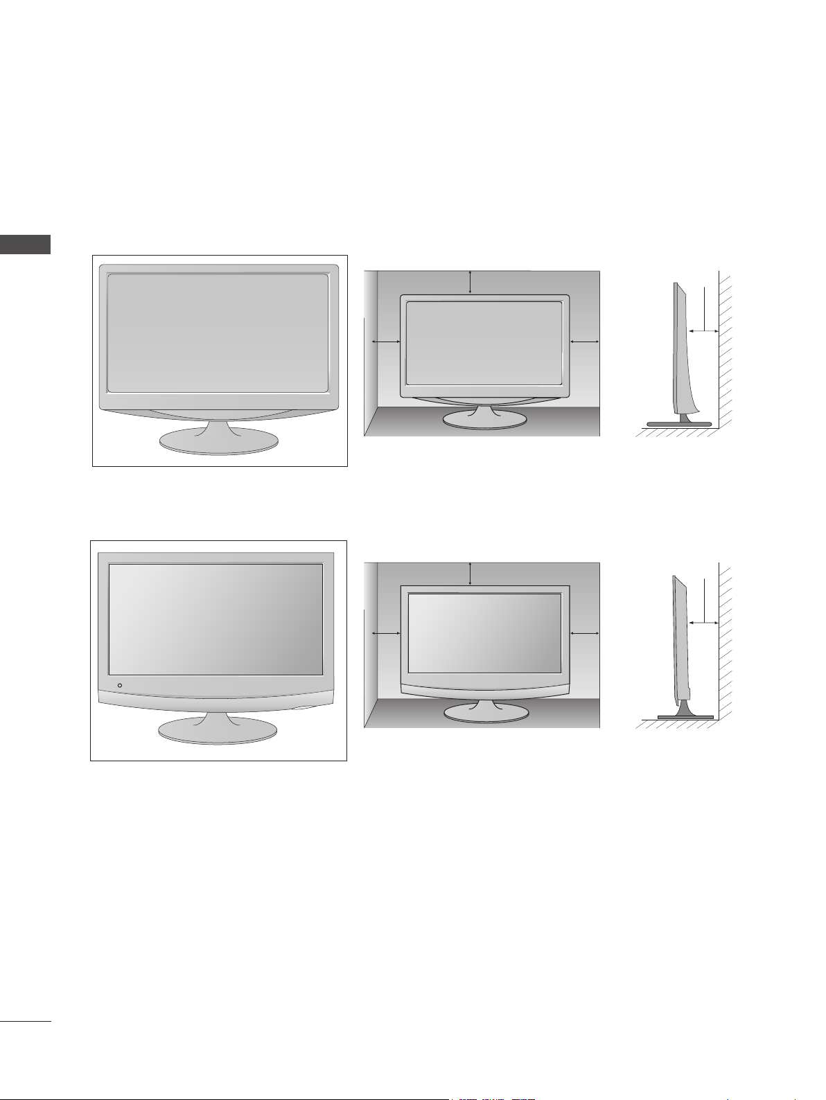
DESKTOP PEDESTAL INSTALLATION
■ The image shown may be somewhat different from your set.
For proper ventilation, allow a clearance of 10 cm on each side and from the wall.
<M197WAP/M227WAP/M237WAP>
PREPARATION
<M2062A/M2262A/M2362A/M2762A>
10 cm
10 cm
10 cm
10 cm
10 cm
10 cm
10 cm
10 cm
18
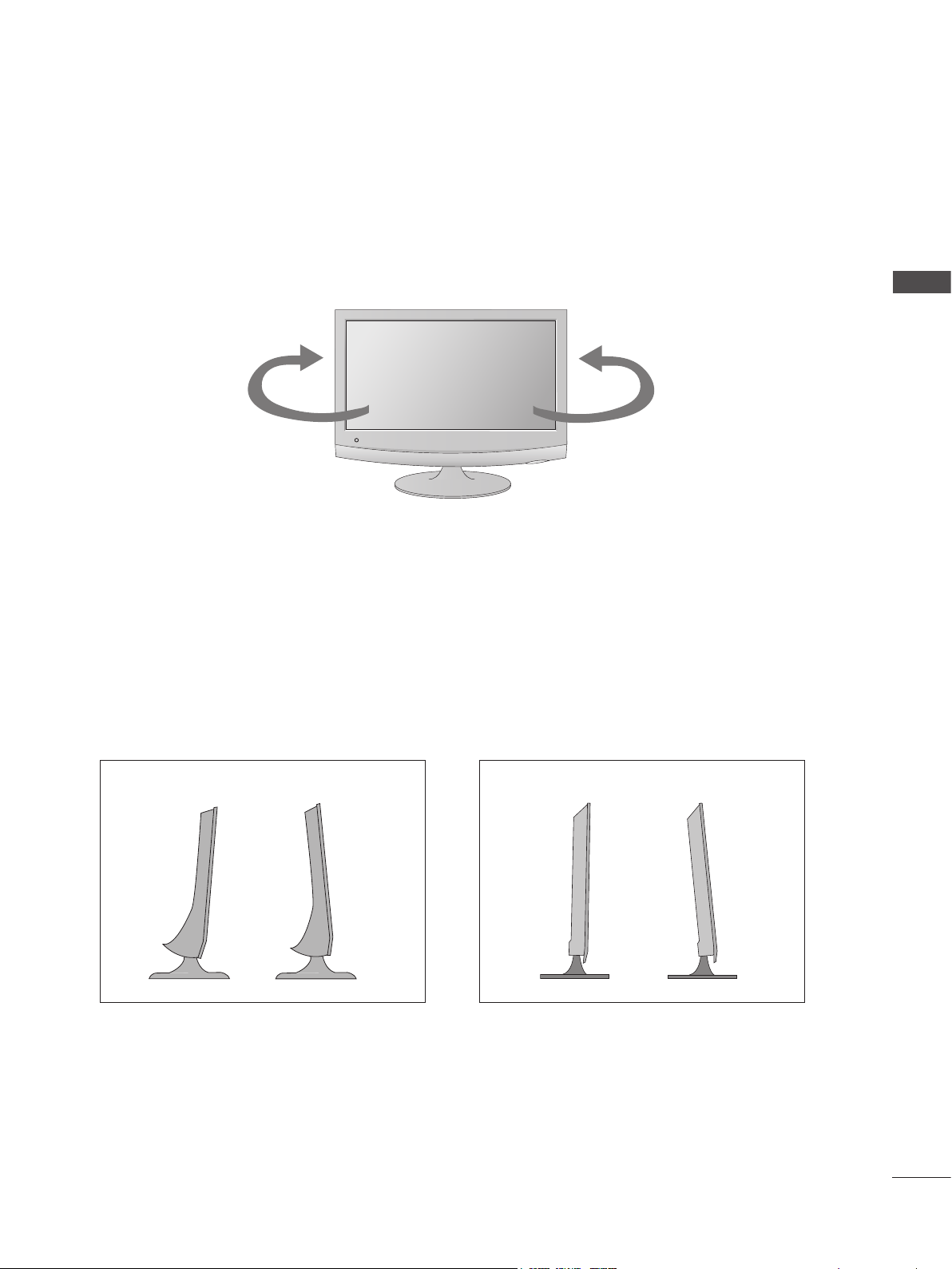
SWIVEL STAND(Only M2762A)
■ The image shown may be somewhat different from your set.
After installing the set, you can adjust the set manually to the left or right direction by 179 degrees to
suit your viewing position.
PREPARATION
179°
POSITIONING YOUR DISPLAY
■ The image shown may be somewhat different from your set.
Adjust the position of the panel in various ways for maximum comfort.
* Tilt range
<M2062A/M2262A/M2362A/M2762A><M197WAP/M227WAP/M237WAP>
-5°-5° 15°15°
179°
19
PREPARATION
!
LOCATION
Position your set so that no bright light or sunlight falls directly onto the screen. Care should be taken not to
expose the set to any unnecessary vibration, moisture, dust or heat. Also, ensure that the set is placed in a
position to allow a free flow of air. Do not cover the ventilation openings on the back cover.
PREPARATION
WARNING
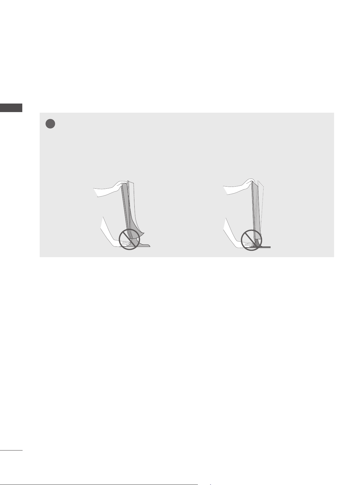
When adjusting the angle of the screen, do not put your finger(s) in between the head of the monitor
and the stand body.
You can hurt your finger(s).
<M2062A/M2262A/M2362A/M2762A><M197WAP/M227WAP/M237WAP>
20
SECURING THE SET TO THE WALL TO PREVENT FALLING
!
WHEN THE SET IS USED ON A STAND (Only M2762A)
■ Image shown may differ from your set.
We recommend that you set up the set close to a wall so it cannot fall over if pushed backwards.
Additionally, we recommend that the set be attached to a wall so it cannot be pulled in a forward direc-
tion, potentially causing injury or damaging the product.
Caution: Please make sure that children don’t climb on or hang from the set.
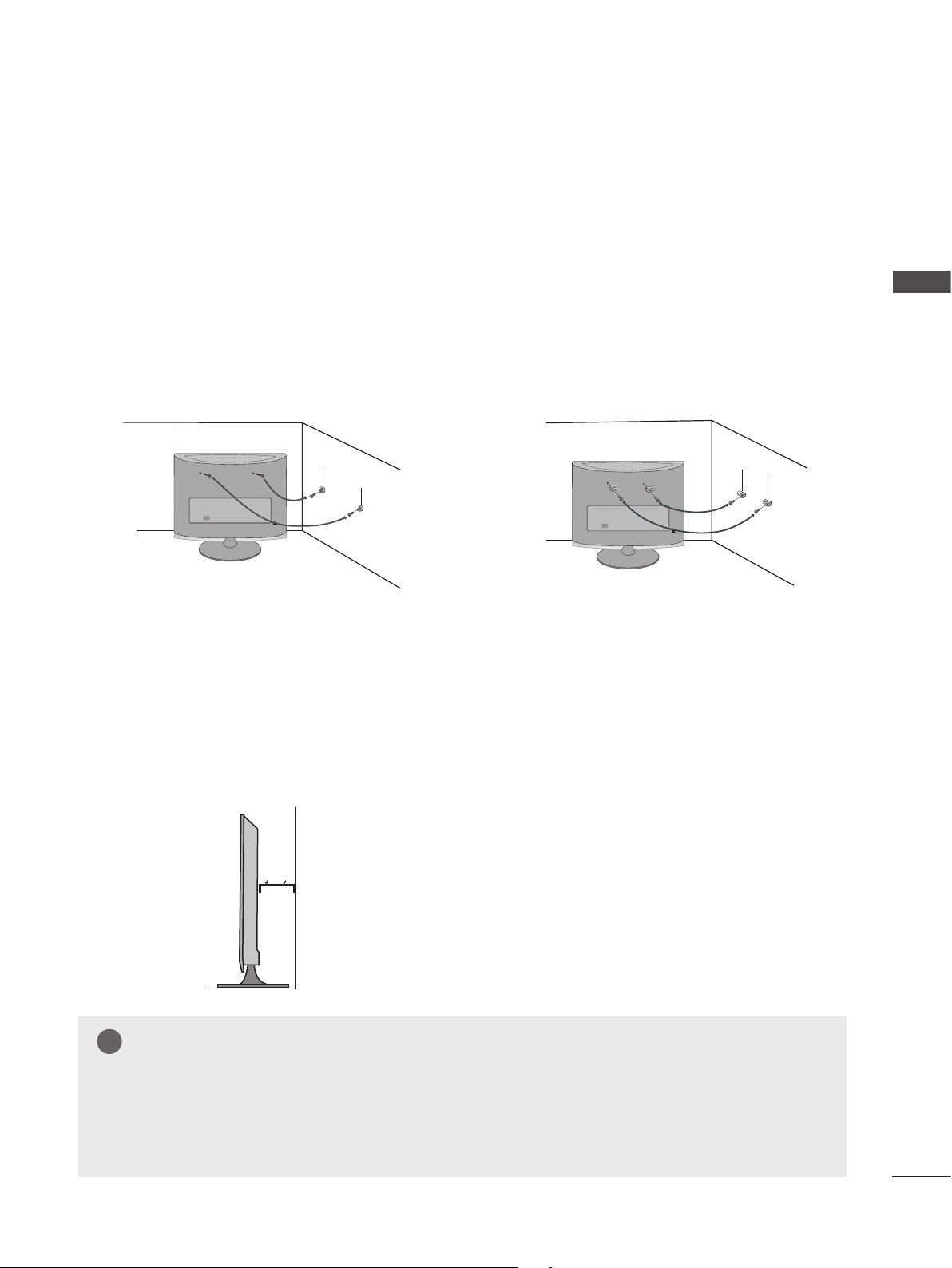
■ Insert the eye-bolts (or set brackets and bolts) to tighten the product to the wall as shown in the pic-
ture.
* If your product has the bolts in the eye-bolts position before inserting the eye-bolts, loosen the bolts.
* Insert the eye-bolts or set brackets/bolts and tighten them securely in the upper holes.
Secure the wall brackets with the bolts (sold separately) to the wall. Match the height of the bracket
that is mounted on the wall to the holes in the product.
Ensure the eye-bolts or brackets are tightened securely.
PREPARATION
■ Use a sturdy rope or cord (sold separately) to tie the
product. It is safer to tie the rope so it becomes horizon-
tal between the wall and the product.
NOTE
► When moving the set, undo the cords first.
► Use a platform or cabinet strong enough and large enough to support the size and weight of the set.
► To use the set safely make sure that the height of the bracket on the wall and the one on the set are the same.
21
PREPARATION
!
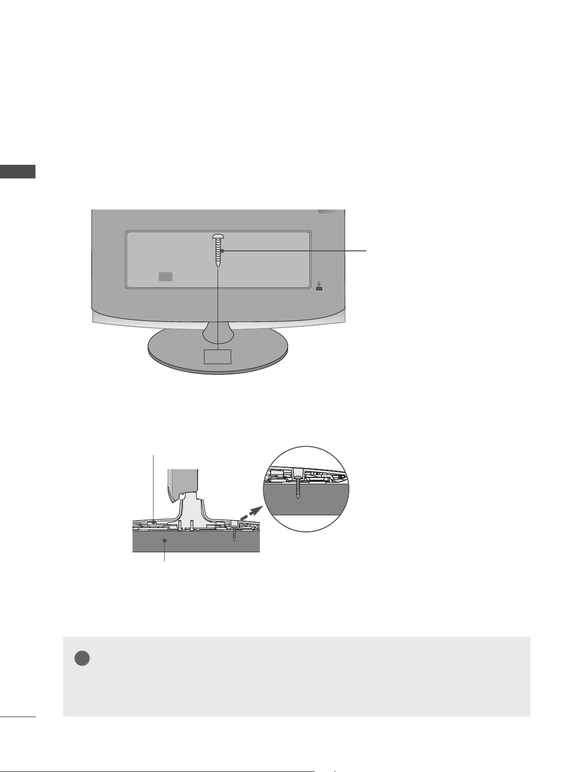
ATTACHING THE TV TO A DESK (Only M2762A)
■ Image shown may differ from your set.
PREPARATION
The TV must be attached to desk so it cannot be pulled in a forward/backward direction,potentially causing injury or damaging the product.Use only an attached screw.
1-Screw
(provided as parts of the product)
Stand
Desk
WARNING
► To prevent TV from falling over,the TV should be securely attached to the floor/wall per installation instructions.
Tipping,shaking, or rocking the machine may cause injury.
22
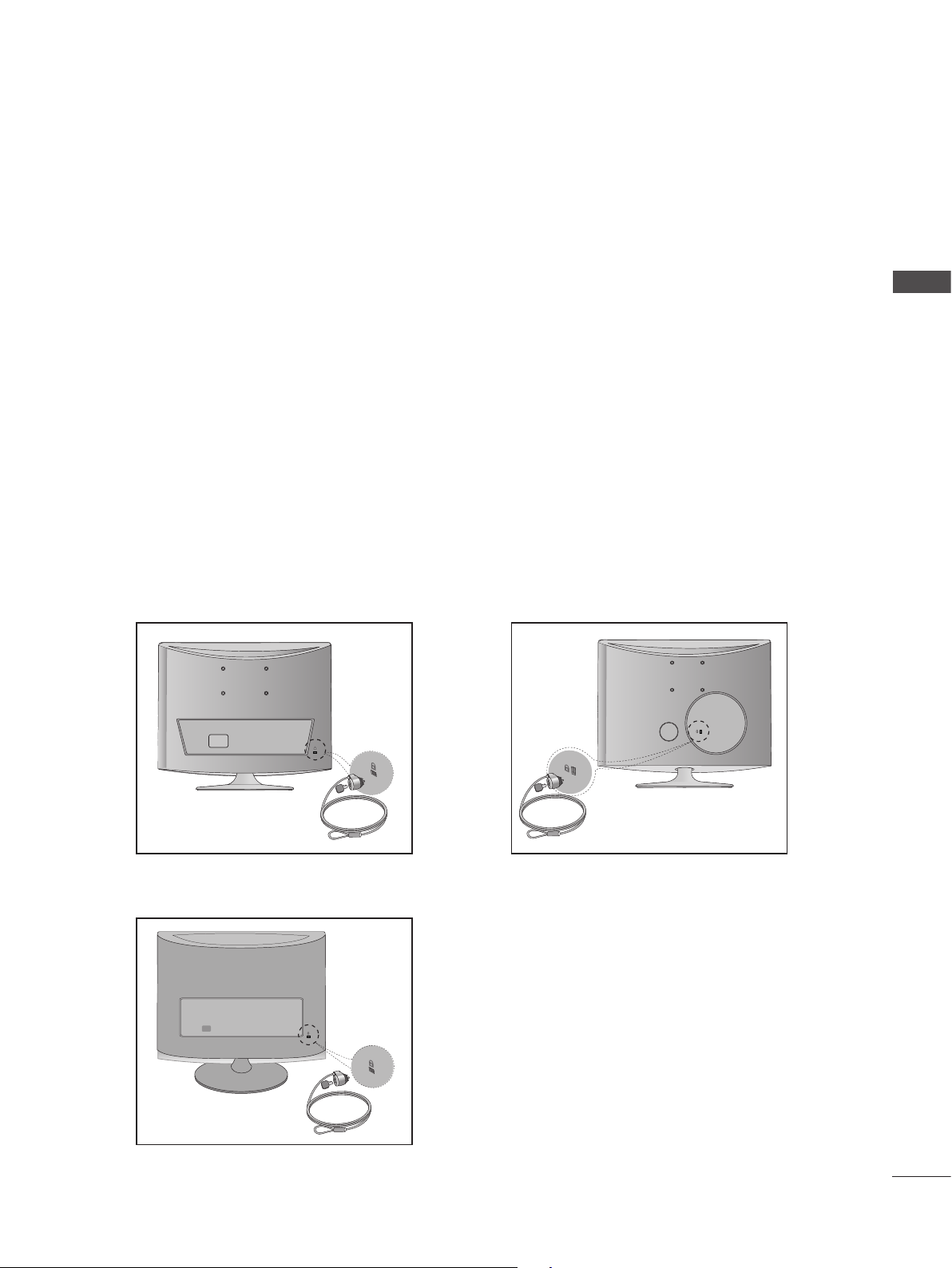
KENSINGTON SECURITY SYSTEM
- The product is equipped with a Kensington Security System connector on the back panel. Connect the
Kensington Security System cable as shown below.
- For detailed installation and use of the Kensington Security System, refer to the user’s guide provided
with the Kensington Security System.
For further information, contact http://www.kensington.com, the internet homepage of the Kensington
company. Kensington sells security systems for expensive electronic equipment such as notebook
PCs and LCD projectors.
NOTE
- The Kensington Security System is an optional accessory.
NOTES
a. If the product feels cold to the touch, there may be a small “flicker” when it is turned on.
This is normal, there is nothing wrong with product.
b. Some minute dot defects may be visible on the screen, appearing as tiny red, green, or blue spots.
However, they have no adverse effect on the monitor’s performance.
c. Avoid touching the LCD screen or holding your finger(s) against it for long periods of time.
Doing so may produce some temporary distortion effects on the screen.
PREPARATION
<M197WAP/ M227WAP >
<M2062A/M2262A/M2362A/M2762A>
<M237WAP>
23
EXTERNAL EQUIPMENT SETUP
■ To prevent damage do not connect to the mains outlet until all connections are made between the devices.
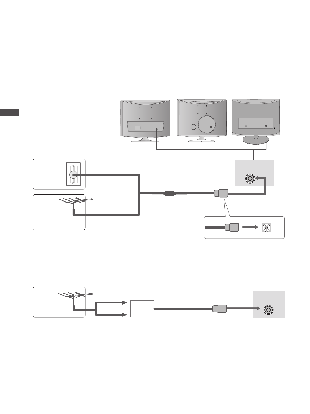
ANTENNA CONNECTION
■ For optimum picture quality, adjust antenna direction.
■ An antenna cable and converter are not supplied.
<M237WAP><M197WAP/ M227WAP >
EXTERNAL EQUIPMENT SETUP
<M2062A/M2262A/
M2362A/M2762A>
Wall
Antenna
Socket
Outdoor
Antenna
Antenna
Multi-family Dwellings / Apartments
(Connect to wall antenna socket)
RF Coaxial Wire (75 Ω)
Single-family Dwellings / Houses
(Connect to wall jack for outdoor antenna)
UHF
Signal
Amplifier
ANTENNA/
CABLE IN
ANTENNA/
CABLE IN
24
VHF
■ In poor signal areas, to get better picture quality, install a signal amplifier to the antenna as shown above.
■ If signal needs to be split for two sets, use an antenna signal splitter for connection.
ANTENNA/
CABLE IN
EXTERNAL EQUIPMENT SETUP
■ To avoid damaging any equipment, never plug in any power cords until you have finished connecting all equipment.
■ The image shown may be somewhat different from your set.
HD RECEIVER SETUP
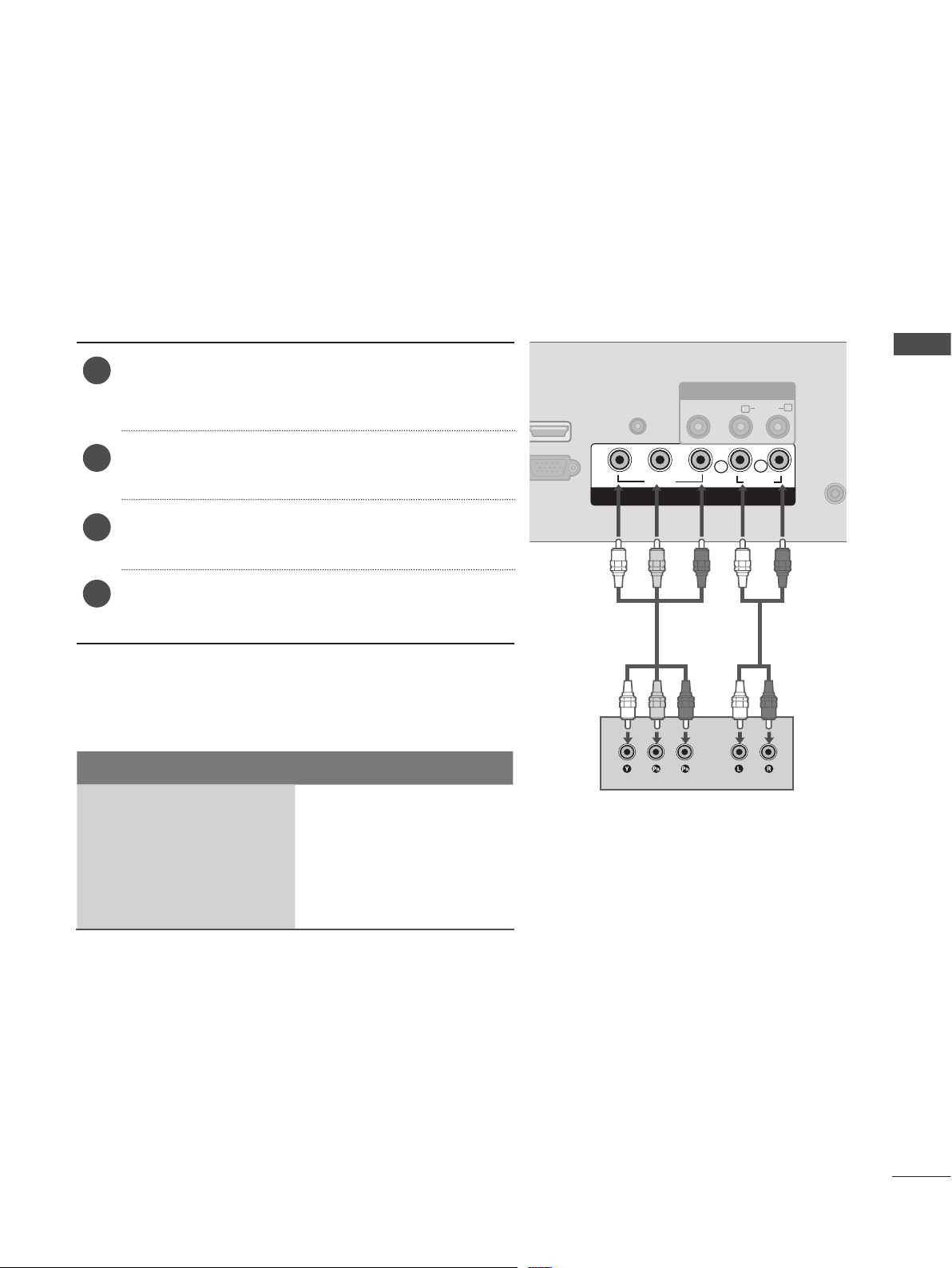
When connecting with a component cable
Connect the video outputs (Y, PB, PR) of the digital
1
set-top box to the COMPONENT IN VIDEO jacks on
the SET.
Connect the audio output of the digital set-top box
2
to the COMPONENT IN AUDIO jacks on the SET.
Turn on the digital set-top box. (Refer to the owner’s
3
manual for the digital set-top box.)
Select COMPONENT input source using the INPUT
4
button on the remote control.
Signal Component
480i / 576i O
HDMI IN
Y
AUDIO IN
(RGB)
P
B
VIDEO
AV IN
VIDEO AUDIO
(MONO)
P
R
L
COMPONENT IN
L
R
AUDIO
EXTERNAL EQUIPMENT SETUP
R
480p / 576p O
720p O
1080i / 1080p O
25
EXTERNAL EQUIPMENT SETUP
AUDIO IN
(RGB)
VIDEO
VIDEO AUDIO
(MONO)
AUDIO
Y
P
B
P
R
L
R
HDMI IN
ANTENNA/
CABLE IN
L
R
RGB IN (PC)
COMPONENT IN
AV IN
O
R
ANTENNA/
CABLE IN
!
EXTERNAL EQUIPMENT SETUP
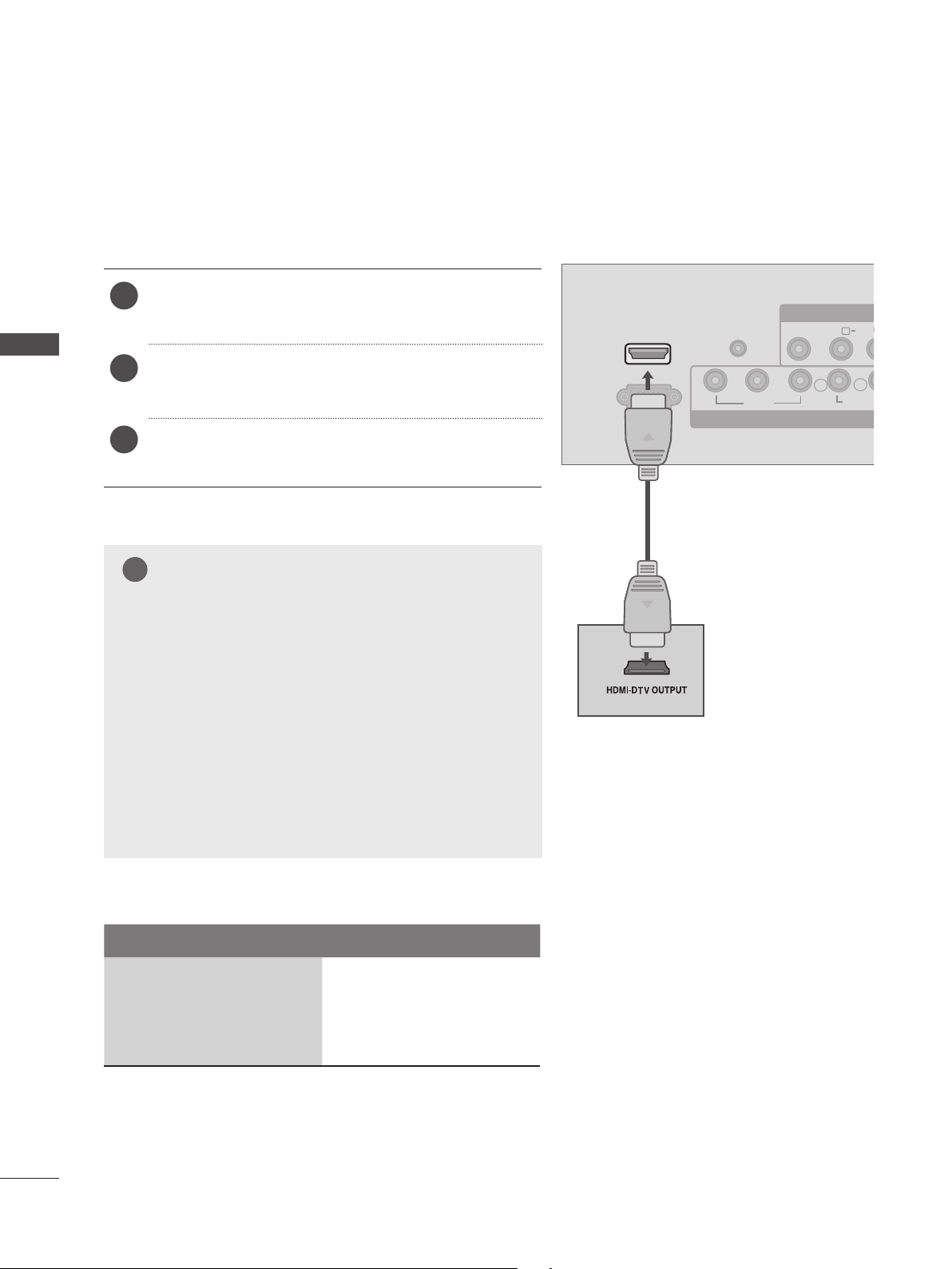
Connecting a set-top box with a HDMI cable
Connect the HDMI output of the digital set-top box to
1
the HDMI IN jack on the SET.
Select HDMI input source using the INPUT button on
2
the remote control.
Turn on the digital set-top box. (Refer to the owner’s
3
manual for the digital set-top box.)
NOTE
►SET
can receive the video and audio signal simultane-
ously with using a HDMI cable.
► If the digital set-top box supports Auto HDMI function, the
output resolution of the source device will be automatically
SET
to 1920 x 1080p.
► If the digital set-top box player does not support Auto HDMI,
you need to
To get the best picture quality, adjust the output resolution of the source device to 1920 x 1080p .
SET
the output resolution appropriately.
HDMI IN
RGB IN (PC)
Y
AUDIO IN
(RGB)
PB
VIDEO
AV IN
VIDEO AUDI
(MONO)
PR
L
COMPONENT IN
L
R
AUDIO
► We recommend less than 10 m for HDMI cable.
Signal HDMI
480p / 576p O
720p O
1080i / 1080p O
26
 Loading...