

LG M197WAE-PM Owner's Manual

ENGLISH
OWNER’S MANUAL
MONITOR TV
Please read this manual carefully before operating
your set and retain it for future reference.
MONITOR TV MODELS
M197WA
M197WAE
www.lge.com

Before Connecting to the PC
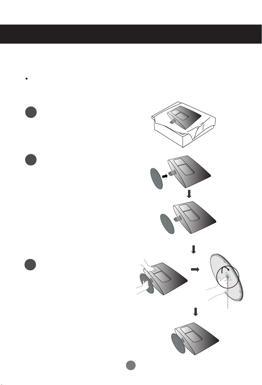
Stand Installation
Before setting up the product, ensure that the power supply, the computer system,
and other attached devices is turned off.
Carefully place the product screen side
1
down on a cushioned surface that will
protect product and screen from damage.
Insert the stand base into the product
2
Attach the monitor to the Stand Base
3
by turning the screw to the right.
* Turn the screw by using the screw
handle
Screw
1
Before Connecting to the PC
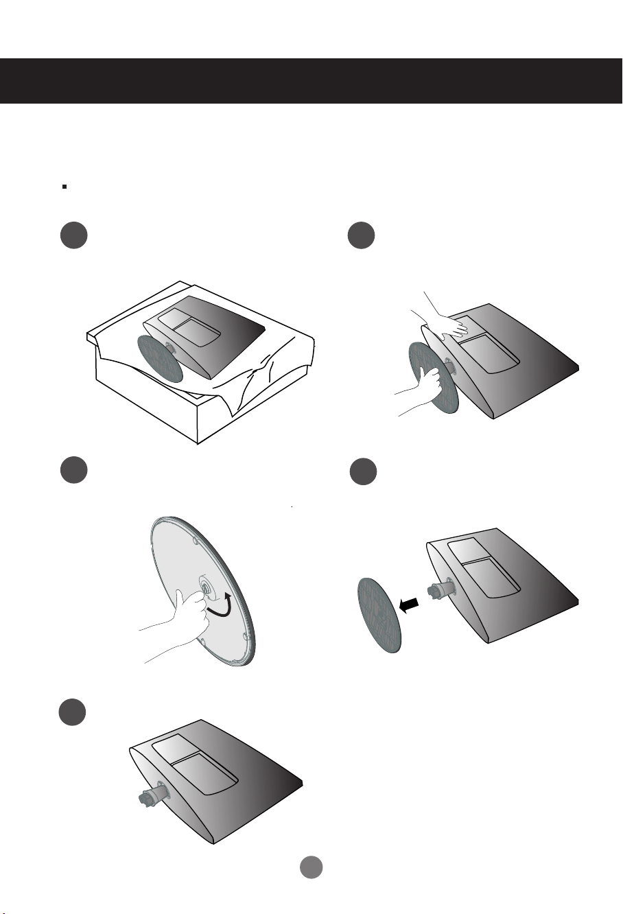
Detaching Stand
Before setting up the product, ensure that the power supply, the computer system,
and other attached devices is turned off.
Place the set screen side down on a
1
cushion or soft cloth.
Turn the screw by using the screw handle
3
Detach the monitor to the Stand
2
Base by turning the screw to the left.
Pull the stand base.
4
5
2
Before Connecting to the PC
Before setting up the product, ensure that the power supply, the computer system,
and other attached devices is turned off.
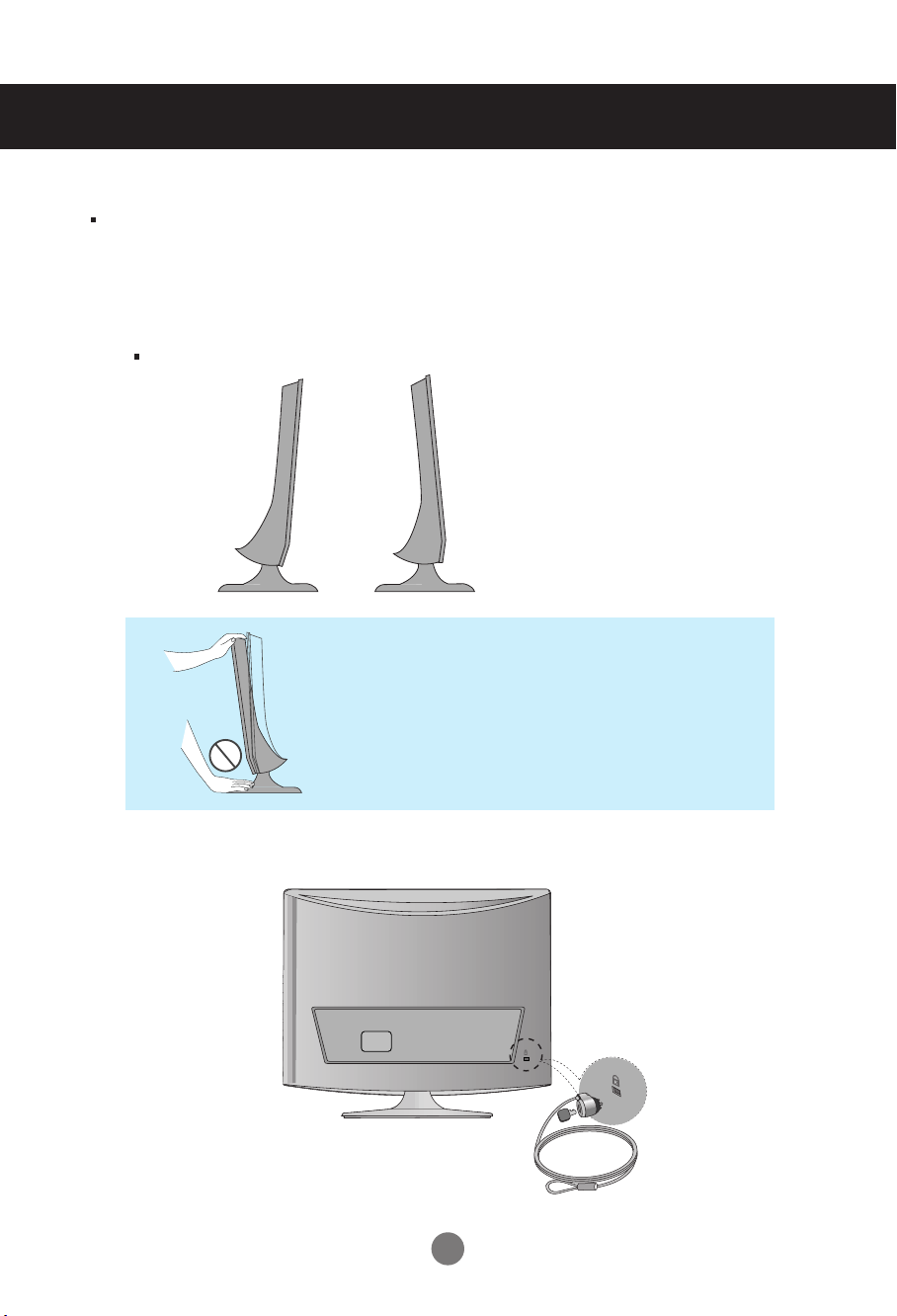
Positioning your display
1. Adjust the position of the panel in various ways for maximum comfort.
Tilt Range
-6
to -2
°
°
12°to 18
°
Warning:
When adjusting the angle of the screen, do not put
your finger(s) in between the head of the monitor
and the stand body. You can hurt your finger(s).
Theft prevention locking device
Use this locking cable
separately if required.
Locking Device
(This has to be purchased
) to prevent theft.
3
Before Connecting to the PC
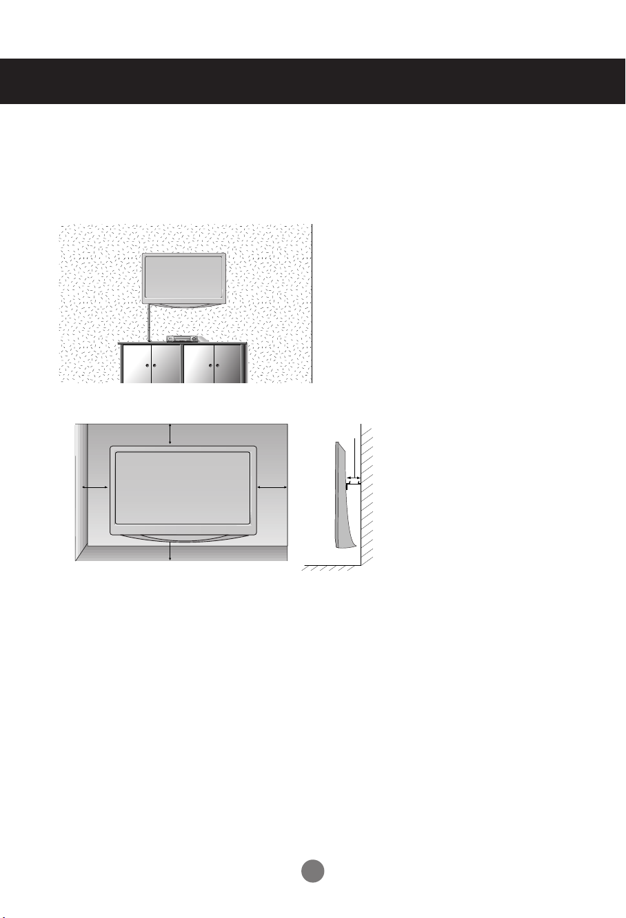
WALL MOUNT:HORIZONTAL INSTALLATION
For proper ventilation,allow a clearance of 10 cm on each side and from the wall. Detailed installation
instructions are available from your dealer,see the optional Tilt Wall Mounting Bracket Installation and
Setup Guide.
10 cm
10 cm
10 cm
10 cm
10 cm
LOCATION
Position your set so that no bright light or sunlight falls directly onto the screen. Care should be taken
not to expose the set to any unnecessary vibration, moisture, dust or heat. Also, ensure that the set is
placed in a position to allow a free flow of air. Do not cover the ventilation openings on the back cover.
If you intend to mount the set to a wall, attach Wall mounting interface (optional parts) to the back of the
set. When you install the set using the wall mounting interface (optional parts), attach it carefully so it
will not drop.
- Be sure to use screws and a wall mount that meet VESA standards.
- Using screws longer than those recommended might damage the product.
- Using screws that do not meet VESA standards might either damage the product or result in it coming
away from the wall. We will not be held responsible for any damage resulting from failure to follow
these instructions.
<Screw Mounting Interface Dimension >
100 mm x 100 mm hole spacing
4
Name and Function of the Parts
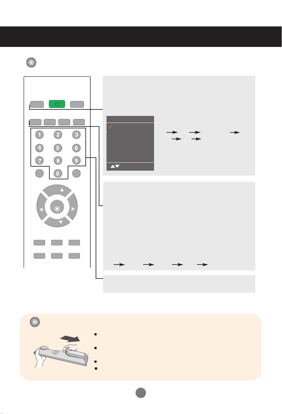
Name of the Remote Control Buttons
TV/PC
MTS
MUTE
VOL
MENU
APC
POWER
A.PROG
REVIEW
MEMORY/ERASE
CH
ENTER
CH
DASP
INPUT
CAPTION
FCR
VOL
SLEEP
ARC/
*
TV/PC :
Selects TV or PC mode.
Switches the set on.
POWER
INPUT
Input
TV
AV
Component
RGB
DVI
HDMI
OK
Each time you press the Input button it will
change to
TV AV Component
RGB DVI HDMI
If nothing is inputted for several seconds the
screen will automatically move to the
selected menu.
MTS
Press repeatedly to select Mono, Stereo, SAP sound tone.
But Stereo, SAP mode are available only if included on the broadcast signal.
A.PROG
Auto Channel Button
PC: Automatic adjustment function (Operational for the analog signal only)
MEMORY/ERASE
User can do manual channel selection and store or erase individual
channels.
CAPTION
Select a closed caption
Off Mode1 Mode2 Text1 Text2
Number buttons
Able to directly select and change channel.
Inserting batteries into remote control.
Open the battery compartment cover on the back and install the
batteries matching correct polarity (+ with +, - with -)
Install two 1.5 V AAA batteries. Don't mix old or used batteries with new
ones.
Close cover.
To remove the batteries, prefrom the installation actions in reverse.
5
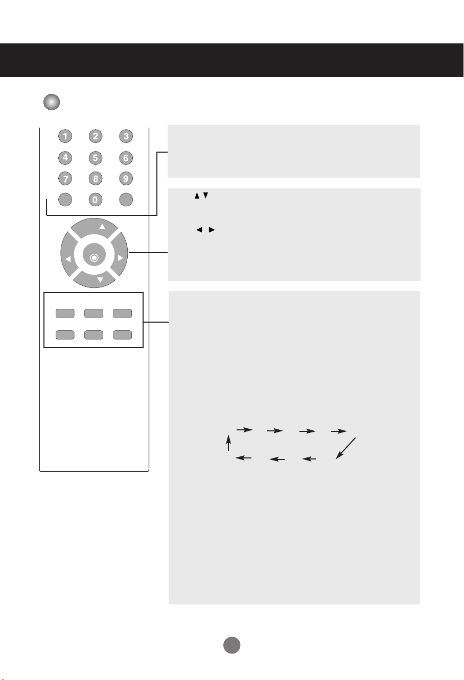
Name and Function of the Parts
CH
CH
ENTER
MUTE
FCR
MENU
REVIEW
SLEEP
APC
DASP
ARC/
VOL
VOL
*
Name of the Remote Control Buttons
MUTE
Switches the sound on or off.
FCR
Favorite channel button.
CH ( ) Buttons
Up and Down Button.
Able to change channel.
VOL ( ) Buttons
Volume Button
ENTER Button
Use when functional adjustment is completed.
MENU
Use this button to enter the On Screen Display menu.
REVIEW
Turn to the last channel viewed.
SLEEP : SLEEP Timer
You can set a time period after which the all modes should switch
itself to standby.
Press the key repeatedly to select the number of minutes.
Press the key repeatedly to select the number of minutes.
_ _ _ (off)
240 180
APC Button
Press repeatedly to select Clear, Optimum, Soft, User picture mode.
(Auto Picture Control)
DASP Button
10
(Digital Auto Sound Processing)
20 30
120
60
90
Use this button to select the sound tone.
Press repeatedly to select Flat, Music, Movie, Sports, User
ARC/
*
To select the image size of the screen.
•
When TV, AV mode: 16:9, Horizon, Zoom1,Zoom2, 4:3
• When RGB/DVI/HDMI/Component mode
6
: 16:9, 4:3
sound tone.
Name and Function of the Parts
AC IN
AC IN
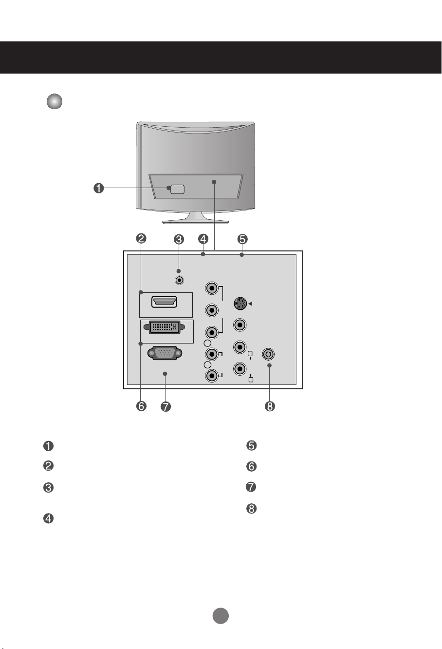
Rear View
COMPONENTINAV IN
AUDIO IN
(RGB/DVI)
HDMI IN
DVI-D IN (PC)
RGB IN (PC)
Y
S-VIDEO
P
B
VIDEO
P
R
L
AUDIO
R
VIDEO AUDIO
(MONO)
ANTENNA/
CABLE IN
L
R
Power Connector : Connect the power cord.
HDMI Digital Signal Connector
RGB, DVI Sound Jack : Connect to the jack in
the PC sound card.
Component Input Terminal
7
AV Input Terminal
DVI Digital Signal Connector
D-Sub Analog Signal Connector
TV Tuner Jack : Connect the antenna.
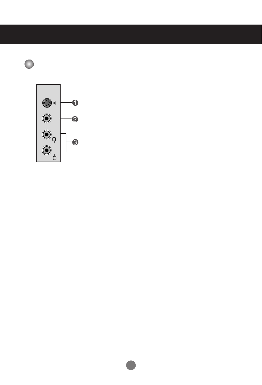
Name and Function of the Parts
VIDEO AUDIO
(MONO)
S-VIDEO
L
R
AC IN
AV Input Terminal
S-Video Input Terminal
Video Input Terminal
Audio Input Terminal
8
Connecting to External Devices
RGB IN (PC)
AUDIO IN
(RGB/DVI)
VIDEO
COMPONENTINAV IN
VIDEO AUDIO
(MONO)
S-VIDEO
AUDIO
Y
P
B
P
R
L
R
DVI-D IN (PC)
HDMI
AC IN AC IN
ANTENNA/
CABLE IN
L
R
RGB IN (PC)
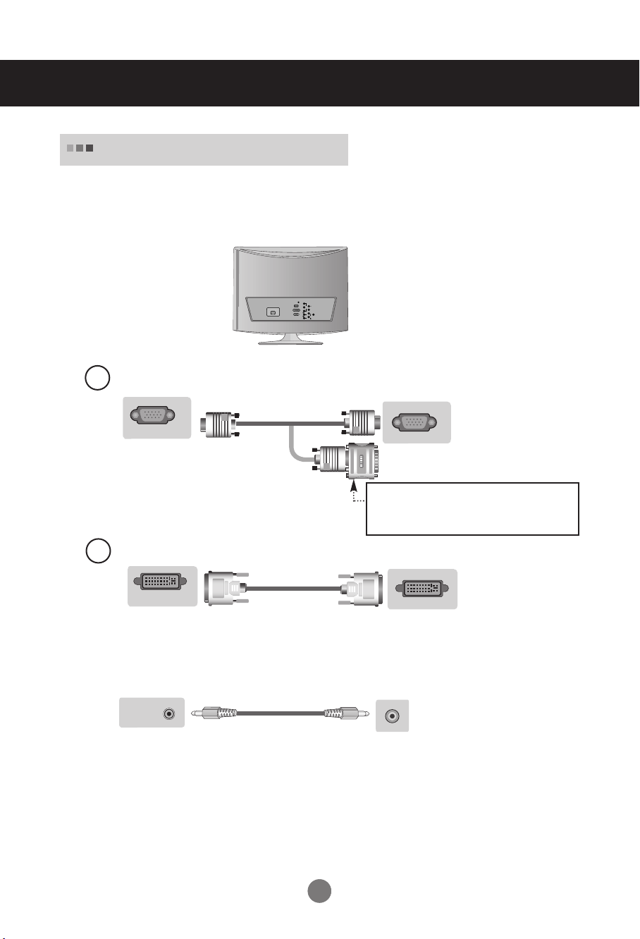
Connecting to your PC
First of all, see if the computer, product and the peripherals are turned off.
1.
Then, connect the signal input cable.
Rear side of the product.
Connecting with the D-Sub signal input cable.
A
Rear side of the product
.
Macintosh Adapter (Not included)
Use the standard Macintosh adapter since an
incompatible adapter is available in the market.
(Different signaling system)
Connecting with the DVI signal input cable.
B
DVI-D IN (PC)
Rear side of the product.
Connect the audio cable.
2.
AUDIO IN
(RGB/DVI)
Audio cable
Rear side of the product.
•
Make sure to check the sound card connection terminal in the PC before connecting to the product.
If the PC sound card supports both Speaker Out and Line Out, change it to Line Out by setting the jumper
or the PC application. (For more details, refer to the sound card user’s guide.)
- Speaker Out : The terminal connected to the speaker that is not equipped with an amplifier.
- *Line Out : The terminal connected to the speaker equipped with an amplifier.
If Audio Out in the PC sound card has only Speaker Out, reduce the PC volume. This product is integrated
with an amplifier.
9
9
 Loading...