

Page 1

SECTION 1. GENERAL
SERVICING PRECAUTIONS
[CONTENTS]
.....................................................................................................
1-2
ESD PRECAUTIONS
SPECIFICATION
.................................................................................................................
........................................................................................................................
1-4
1-5
SECTION 2. TROUBLESHOOTING
ADJUSTMENTS
TROUBLESHOOTING...............................................................................................................2-3
WAVEFORMS OF MAJOR CHECK POINT...............................................................................2-7
BLOCK DIAGRAM
SCHEMATIC DIAGRAMS
WIREING DIAGRAM................................................................................................................2-26
PRINTED CIRCUIT DIAGRAMS..............................................................................................2-28
INTERNAL BLOCK DIAGRAM OF ICs....................................................................................2-39
PRINTED CIRCUIT DIAGRAMS
.........................................................................................................................
....................................................................................................................
........................................................................................................
..............................................................................................
2-1
2-16
2-18
2-53
SECTION 3. EXPLODED VIEWS
CABINET AND MAIN FRAME SECTION
...................................................................................
3-1
SECTION 4. SPEAKER SECTION
SPEAKER SECTION...................................................................................................................4-1
SECTION 5. REPLACEMENT PARTS LIST
REPLACEMENT PARTS LIST
....................................................................................................
- 1-1-
5-1
Page 2

SECTION 1. GENERAL
SERVICING PRECAUTIONS
[NOTES REGARDING HANDLING OF THE PICK-UP]
Notes for transport and storage
1) The pick-up should always be left in its conductive bag until immediately prior to use.
2) The pick-up should never be subjected to external pressure or impact.
Storage in conductive bag
Drop impact
Repair notes
1) The pick-up incorporates a strong magnet, and so should never be brought close to magnetic materials.
2) The pick-up should always be handled correctly and carefully, taking care to avoid external pressure and
impact. If it is subjected to strong pressure or impact, the result may be an operational malfunction and/or
damage to the printed-circuit board.
3) Each and every pick-up is already individually adjusted to a high degree of precision, and for that reason
the adjustment point and installation screws should absolutely never be touched.
4) Laser beams may damage the eyes!
Absolutely never permit laser beams to enter the eyes!
NEVER look directly at the laser beam, and don!t let
contact fingers or other exposed skin.
Also NEVER switch ON the power to the laser output part (lens, etc.) of the pick-up if it is damaged.
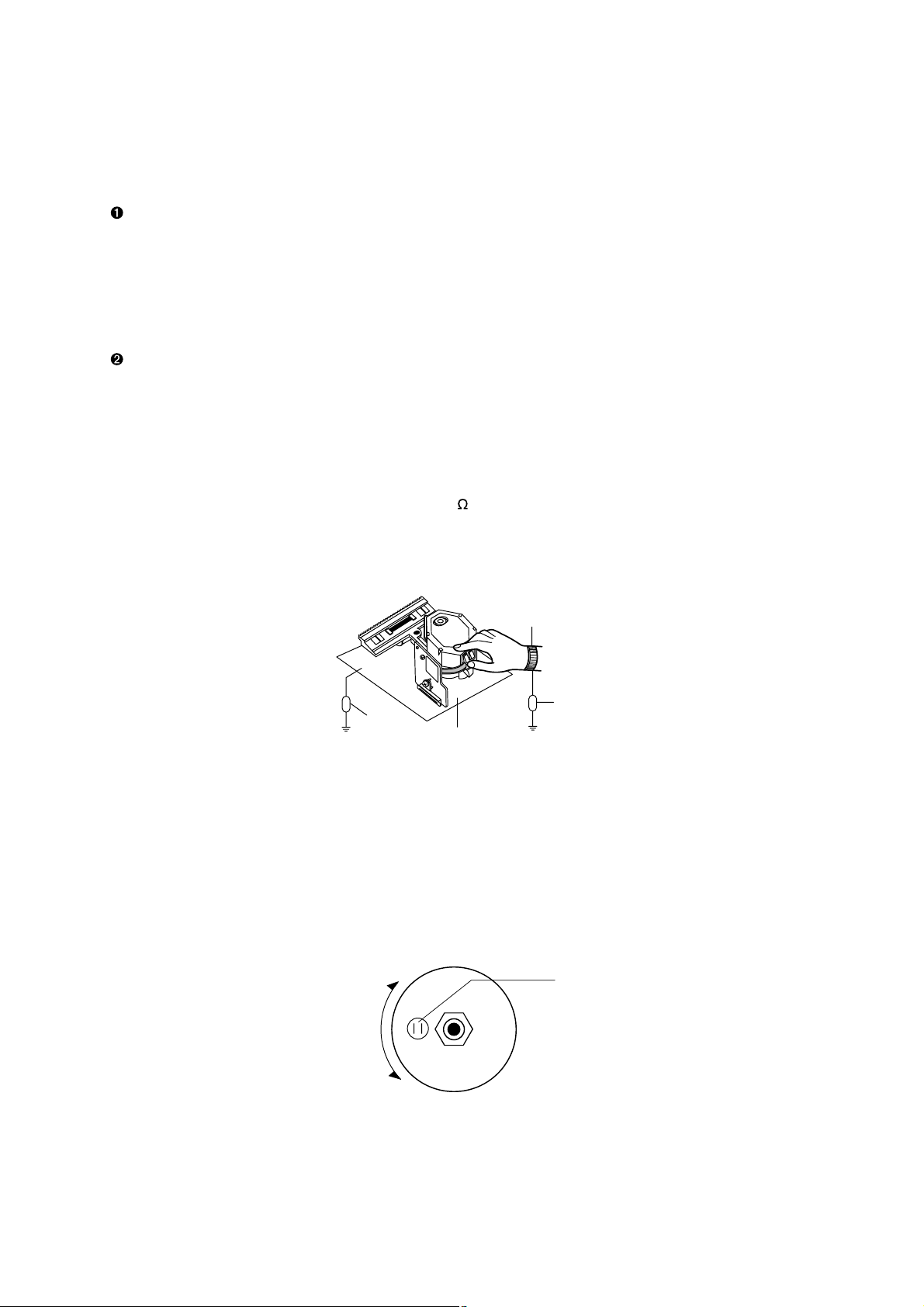
5) Cleaning the lens surface
If there is dust on the lens surface, the dust should be cleaned away by using an air bush (such as used
for camera lens). The lens is held by a delicate spring. When cleaning the lens surface, therefore, a
Magnet
How to hold the pick-up
Cotton swab
Conductive Sheet
cotton swab should be used, taking care not to distort this.
6) Never attempt to disassemble the pick-up.
Spring by excess pressure. If the lens is extremely dirty, apply isopropyl alcohol to the cotton swab. (Do
- 1-2-
Pressure
Pressure
Page 3
[NOTES REGARDING COMPACT DISC PLAYER REPAIRS]
Preparations
1) Compact disc players incorporate a great many ICs as well as the pick-up (laser diode). These
components are sensitive to, and easily affected by, static electricity. If such static electricity is high
voltage, components can be damaged, and for that reason components should be handled with care.
2) The pick-up is composed of many optical components and other high-precision components. Care must
be taken, therefore, to avoid repair or storage where the temperature of humidity is high, where strong
magnetism is present, or where there is excessive dust.
Notes for repair
1) Before replacing a component part, first disconnect the power supply lead wire from the unit
2) All equipment, measuring instruments and tools must be grounded.
3) The workbench should be covered with a conductive sheet and grounded.
When removing the laser pick-up from its conductive bag, do not place the pick-up on the bag. (This is
because there is the possibility of damage by static electricity.)
4) To prevent AC leakage, the metal part of the soldering iron should be grounded.
5) Workers should be grounded by an armband (1M )
6) Care should be taken not to permit the laser pick-up to come in contact with clothing, in order to prevent
static electricity changes in the clothing to escape from the armband.
7) The laser beam from the pick-up should NEVER be directly facing the eyes or bare skin.
Armband
Resistor
Resistor
(1 Mohm)
Conductive
Sheet
(1 Mohm)
CLEARING MALFUNCTION
You can reset your unit to initial status if malfunction occur(button malfunction, display, etc.).
Using a pointed good conductor(such as driver), simply short the RESET jump wire on the inside of the
volume knob for more than 3 seconds.
If you reset your unit, you must reenter all its settings(stations, clock, timer)
NOTE: 1. To operate the RESET jump wire, pull the volume rotary knob and release it.
2. If you wish to operate the RESET jump wire, it is necessary to unplug the power cord.
VOLUME
UP
VOLUME KNOB
DOWN
RESET jump wire
- 1-3-
Page 4

ESD PRECAUTIONS
Electrostatically Sensitive Devices (ESD)
Some semiconductor (solid state) devices can be damaged easily by static electricity. Such components
commonly are called Electrostatically Sensitive Devices (ESD). Examples of typical ESD devices are integrated
circuits and some field-effect transistors and semiconductor chip components. The following techniques should
be used to help reduce the incidence of component damage caused by static electricity.
1. Immediately before handling any semiconductor component or semiconductor-equipped assembly, drain off
any electrostatic charge on your body by touching a known earth ground. Alternatively, obtain and wear a
commercially available discharging wrist strap device, which should be removed for potential shock reasons
prior to applying power to the unit under test.
2. After removing an electrical assembly equipped with ESD devices, place the assembly on a conductive
surface such as aluminum foil, to prevent electrostatic charge buildup or exposure of the assembly.
3. Use only a grounded-tip soldering iron to solder or unsolder ESD devices.
4. Use only an anti-static solder removal device. Some solder removal devices not classified as "anti-static" can
generate electrical charges sufficient to damage ESD devices.
5. Do not use freon-propelled chemicals. These can generate electrical charges sufficient to damage ESD
devices.
6. Do not remove a replacement ESD device from its protective package until immediately before you are ready
to install it. (Most replacement ESD devices are packaged with leads electrically shorted together by
conductive foam, aluminum foil or comparable conductive materials).
7. Immediately before removing the protective material from the leads of a replacement ESD device, touch the
protective material to the chassis or circuit assembly into which the device will by installed.
CAUTION : BE SURE NO POWER IS APPLIED TO THE CHASSIS OR CIRCUIT, AND OBSERVE ALL OTHER
SAFETY PRECAUTIONS.
8. Minimize bodily motions when handing unpackaged replacement ESD devices. (Otherwise harmless motion
such as the brushing together of your clothes fabric or the lifting of your foot from a carpeted floor can
generate static electricity sufficient to damage an ESD device).
[CAUTION. GRAPHIC SYMBOLS]
THE LIGHTNING FLASH WITH APROWHEAD SYMBOL. WITHIN AN EQUILATERAL
TRIANGLE, IS INTENDED TO ALERT THE SERVICE PERSONNEL TO THE PRESENCE
OF UNINSULATED "DANGEROUS VOLTAGE# THAT MAY BE OF SUFFICIENT
MAGNITUDE TO CONSTITUTE A RISK OF ELECTRIC SHOCK.
THE EXCLAMATION POINT WITHIN AN EQUILATERAL TRIANGLE IS INTENDED TO
ALERT THE SERVICE PERSONNEL TO THE PRESENCE OF IMPORTANT SAFETY
INFORMATION IN SERVICE LITERATURE.
- 1-4-
Page 5
Dual-trace
Electronic
SECTION 2. ELECTRICAL SECTION
ADJUSTMENTS
This set has been aligned at the factory and normally will not require further adjustment. As a result, it is not
recommended that any attempt is made to modificate any circuit. If any parts are replaced or if anyone tampers
with the adjustment, realignment may be necessary.
IMPORTANT
1. Check Power-source voltage.
2. Set the function switch to band being aligned.
3. Turn volume control to minimum unless otherwise noted.
4. Connect low side of signal source and output indicator to chassis ground unless otherwise specified.
5. Keep the signal input as low as possible to avoid AGC and AC action.
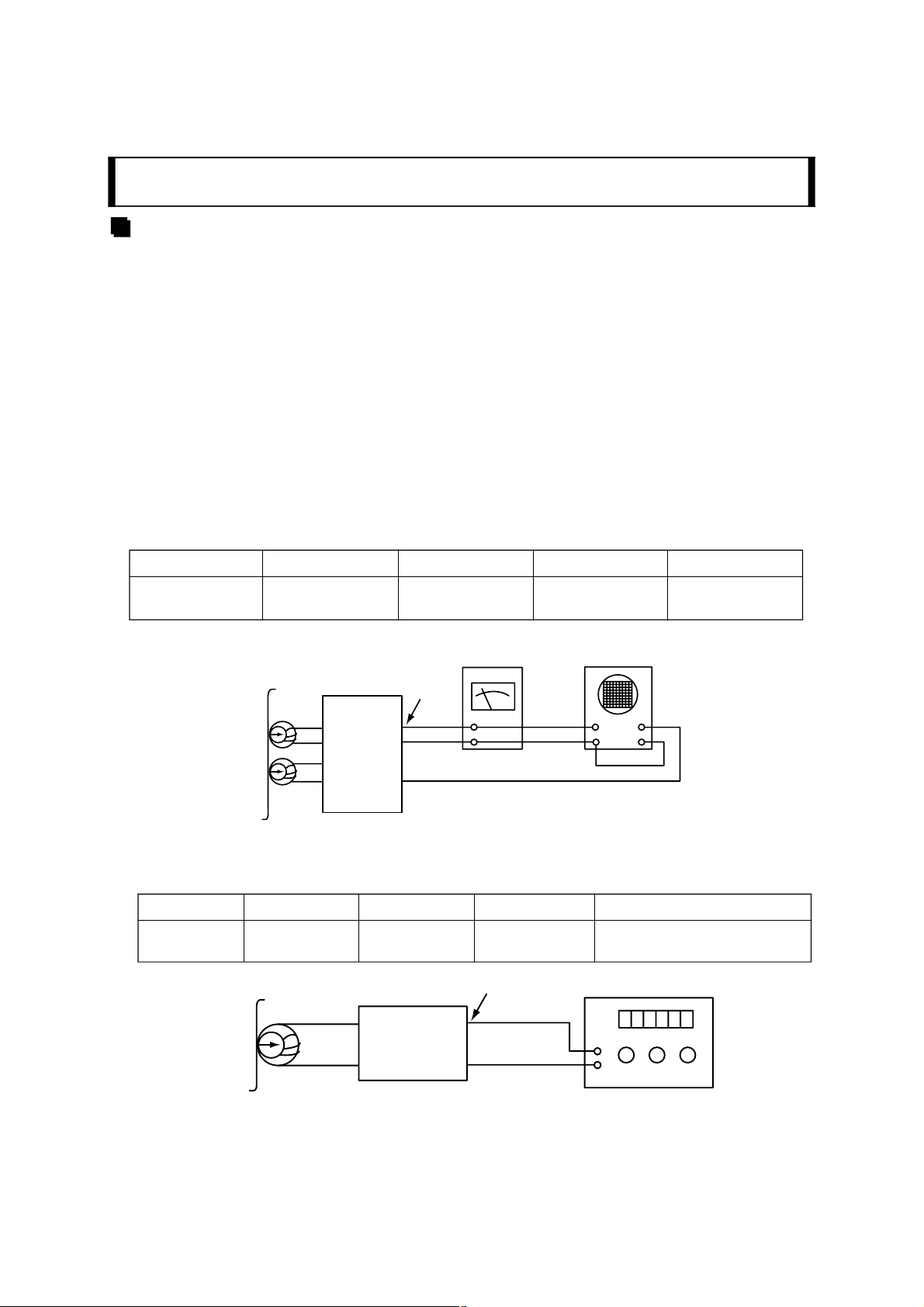
TAPE DECK ADJUSTMENT
1. AZIMUTH ADJUSTMENT
Deck ModeTest TapeTest TapeAdjustmentAdjust for
PalybackMTT-114Speaker Out
DECK Screw
Azimuth Screw
Maximum
synchroscope
CH1 CH2
GND
Test Tape
MTT-114
Voltmeter
Head
L ch
R ch
Playback Mode
Unit
Figure 1. Azimuth Adjustment Connection Diagram
Speaker Out
L out
R out
2. MOTOR SPEED ADJUSTMENT
Deck ModeTest TapeTest TapeAdjustmentAdjust for
Rec/PauseMTT-5511
Head
Test Tape
MTT-5511
Record/Playback
head
Figure 2. Motor Speed Adjustment Connection Diagram
ERASE HEAD
WIRE(PN201)85kHz±5kHz(Auto Reverse)
Record/Playback
and Pause Mode
Unit
PN202
L201
GND
60kHz±5kHz (Auto stop)
Frequency Counter
- 2-1-
Page 6
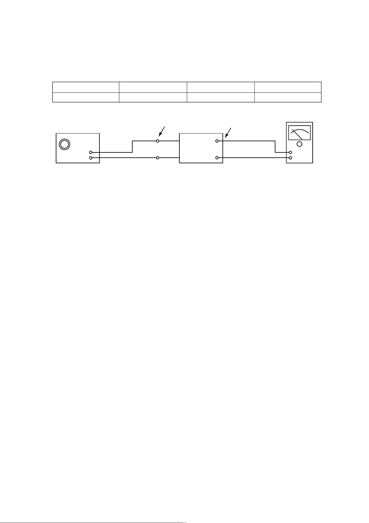
3. TUNER ADJUSTMENT
Electronic
(FM)
ItemTest PointAdjustmentAdjust for
DC VoltageCheck Point TP1, TP2L1010V±50mV
Signal Generator
FM Antenna
Terminal
Unit
GND
Speaker
Figure 3. Tuner(S curve) Adjustment Connection Diagram
OSCILLOSCOPE
- 2-2-
Page 7
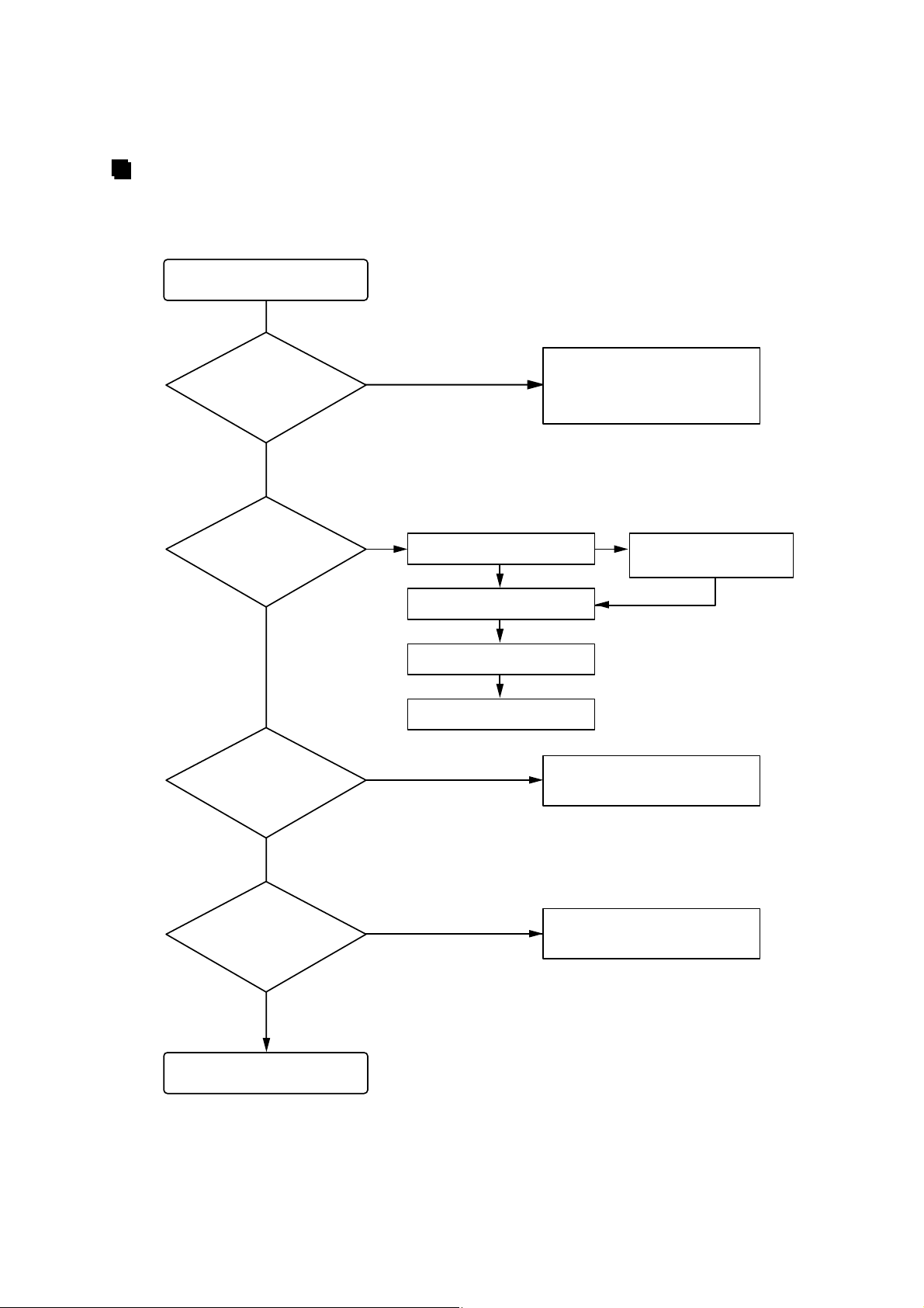
TROUBLESHOOTING
CD PART
Turn power on.
Is power on?
NO
Does initial
read work?
NO
Does it play?
NO
Check the DISK circuit
YES
Check the Laser
YES
Check the focus circuit
YES
Check the TRAKING servo.
NO
Check power supply circuit.
PN508 PIN8, 6.2V
PN508 PIN7, 5V
IC503 PIN2, 3.3V
NONO
Check the connector PN503,
PN504, PN507
Check the tracking servo.
NO
Does it output
audio?
NO
OK
NO
- 2-3-
Check the PN508 PIN1, 3
Page 8

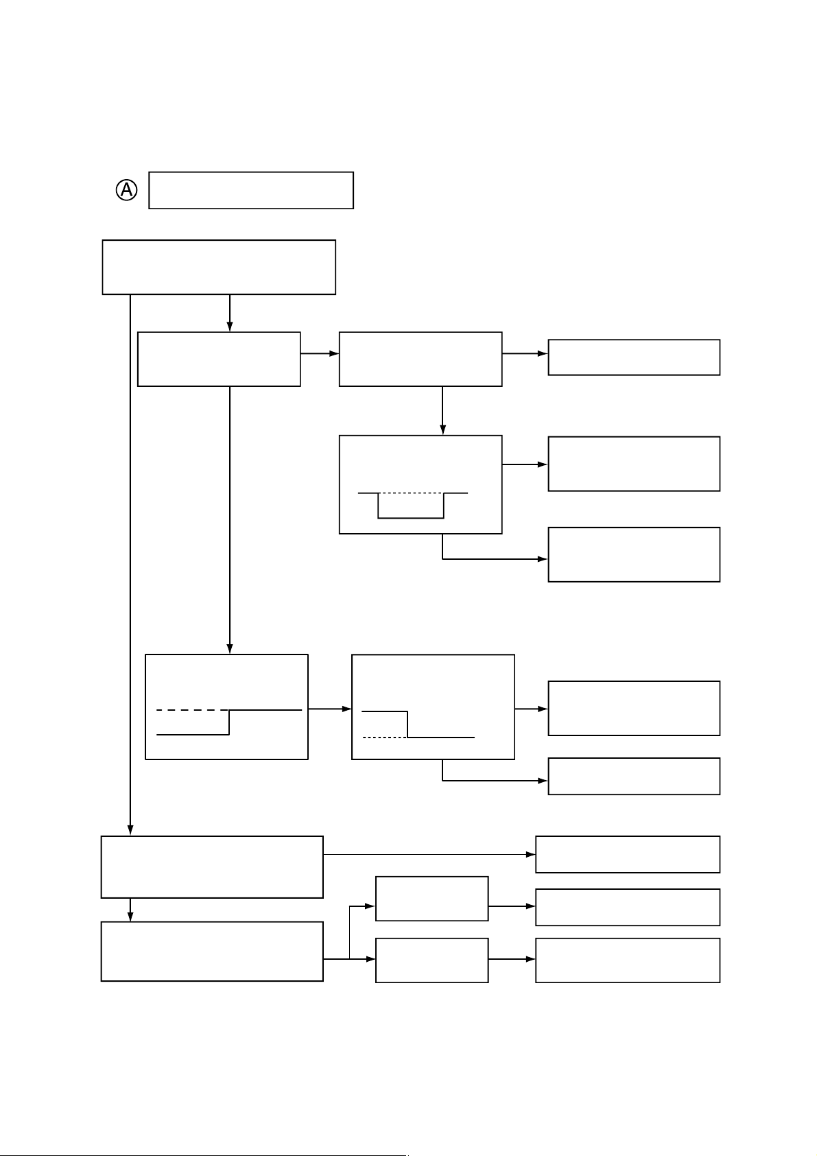
FAILS TO INITIAL READ
Disc motor turns
YES
Does RF waveform appear?
IC501 Pin3
YES
Check the Voltage change of PN 507
NONO
PIN2(OPEN, CLOSE)
YES
Check the Data transferred from PN507
NO
pin8 to CD DSP
5V
0V
NO
YES
Check the Data transferred from PN507
pin6 to MICOM
5V
0V
NO
YES
SLDO Voltage
(IC501 pin23)
2V
NO
1V
0V
YES
Check the change of SL +,
SL - Voltage
(IC502 pin 18, 19)
1.2V
0V
0.8V
NO
Defective connector
PN507
Defective connector
PN507, Defective
MICOM
Defective connector
PN507, Defective
IC501
Defective IC501
Defective IC502
Does laser light?
YES
Does FA+ waveform appear at
IC502 pin18?
focus coil drive wareform.
YES
Does TE waveform appear at
IC501 pin15?
TRACKING ERROR wareform
YES
Is rotation normal?
YES
Is there no dropout of RF signal?
YES
NO
YES
Defective contact PN503
A
Defective PICK-UP
B
Defective IC501
Defective PICK-UP
- 2-4-
Page 9
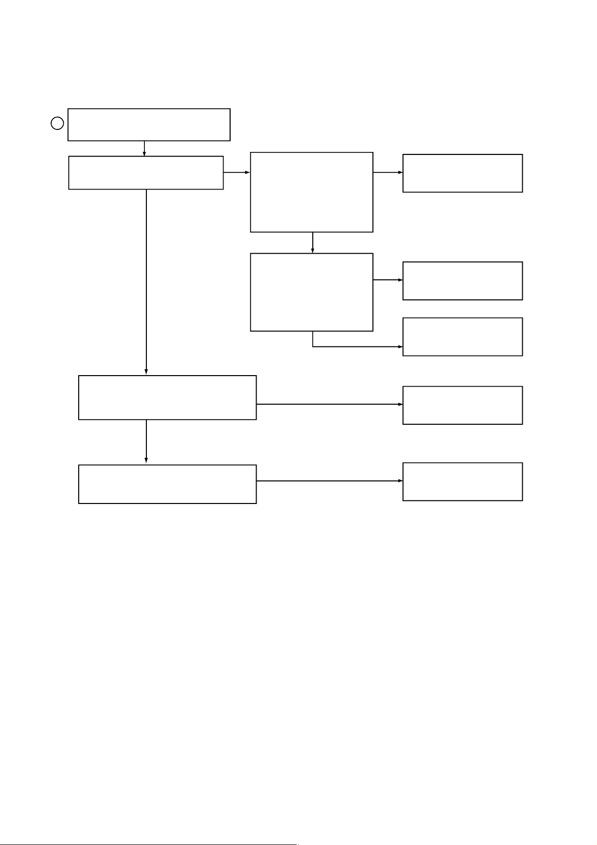
Laser does not light.
Is "3.5V# applied to pin80
of IC801?
YES
NO
Did pickup return to
innermost circular?
YES
Does it stop at inner pick
circular after shift?
NO
Is data transferred from
MICOM IC ?
Does voltage appear at IC
502 pin18, 19?
Is defect output from LM
SW applied to pin 5 of
YES
PN503?
OPEN CLOSE
YES
YES
NO
Defective MICOM.
NO
Defective IC501, 502
Defective slide motor and/or
connector.
NO
Defective LMT SW and/or
connector.
YES
Is power supplied to laser Q501?
(Q501 collector: about 1.8V)
YES
Does laser current flow?
(R508!s voltage are 1.0V)
YES
NO
R508 »1.0V
R508 «1.0V
- 2-5-
YES
YES
Defective MICOM.
Defective connector.
Defective Q 501 and/or laser.
Defective laser and/or
connector.
Page 10
B
Laser lights
Does lens move up/down?
YES
Does FE signal appear?
(IC501 pin 13)
YES
NO
Check the signal of FOCUS
SEARCH
(IC501 Pin 21)
YES
Chekc the signal of PN502
pin 13, 14
YES
NO
Defective IC501
NO
Defective IC502
Open activator and/or connector
NO
Defective IC501
Does DRF signal appear?
(IC501 pin67)
- 2-6-
NO
Degraded laser diode
Defective PICK-UP
Page 11
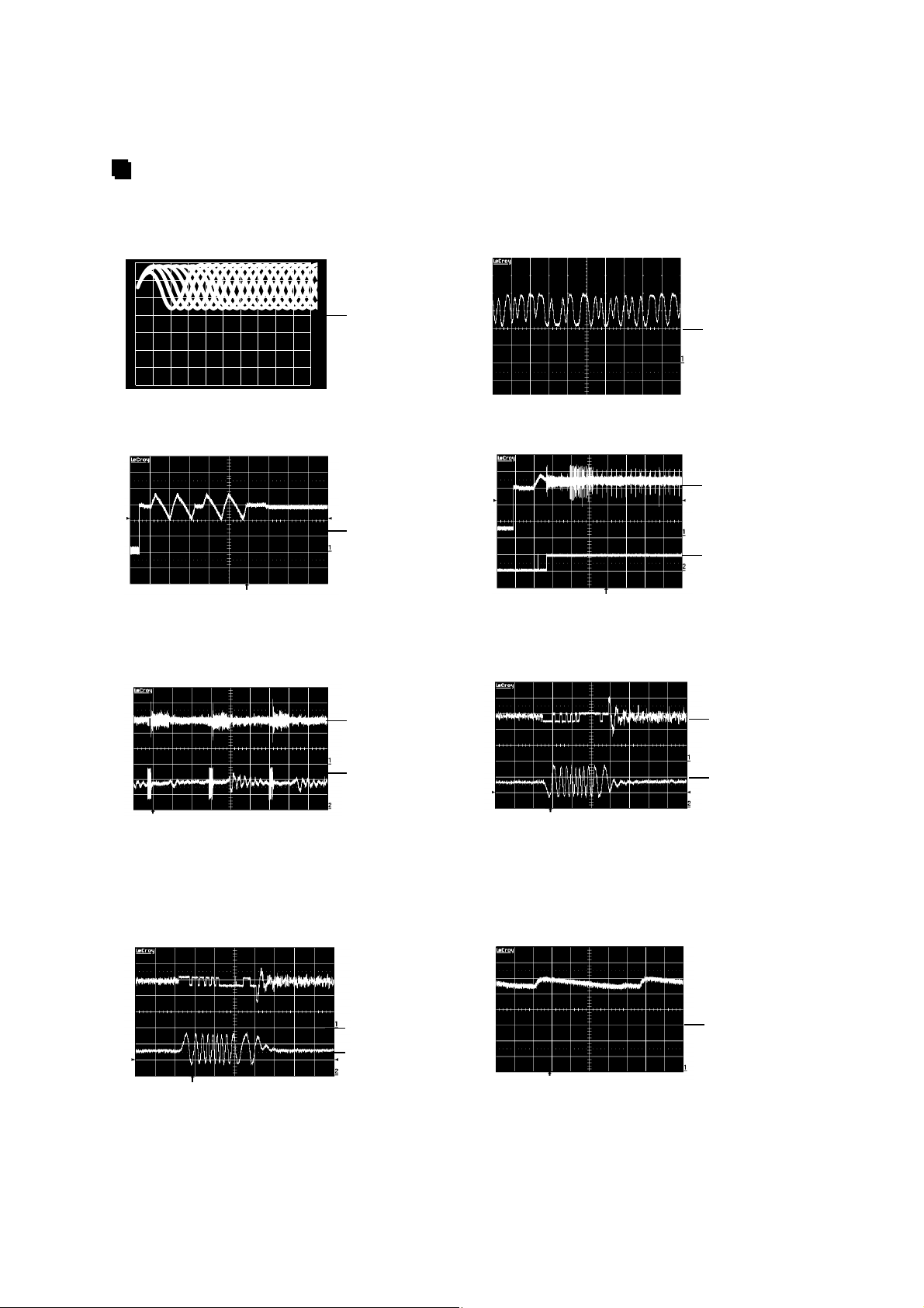
WAVEFORMS OF MAJOR CHECK POINT
1. HF signal (RF signal ) waveform
(IC501 pin4) during normal play
0.5V/Div.
(
500nS/Div.
OV
3. Focus coil drive waveform(IC502 pin13)
When focus search failed or there is no disc on the tray
1S/Div.
(
1V/Div.
OV
4. Tracking coil drive waveform and TE during track
traverse
(1) When time division is 20mS/Div.1V/Div.
2. EFM signal (IC501 pin 3)waveform
during Normal Play
0.5V/Div.
(
5µS/Div.
OV
Focus coil drive waveform(FDO: IC501 pin21) and
DRF(IC501 pin67) when focus search is accomplished
OV
(CH1)
OV
(CH2)
CH1 : FOCUS COIL DRIVE
SIGNAL 2V/Div.
(
CH2 : DRF
(2) When time division 1mS/Div, 1V/Div
(During forward track traverse)
CH1 : TRACKING COIL DRIVE (IC502 pin27)
(
CH2 : TRACKING ERROR (TE: IC501 pin15)
(3) When time division is 0.5nS/div.
(During backward Track Traverse)
CH1 : TRACKING COIL DRIVE
SIGNAL 2V/Div. (IC502 pin27)
(
CH2 : TRACKING ERROR(TE: IC501 pin15)
1V/Div.
OV
(CH1)
OV
(CH2)
1mS/Div.
(
1V/Div.
OV
OV
(CH2)
OV
(CH1)
OV
(CH2)
CH1 : TRACKING COIL DRIVE (IC502 pin27)
SIGNAL 2V/Div.
(
CH2 : TRACKING ERROR (TE: IC501 pin15)
1V/Div.
5. Feed motor drive waveform(IC 502 pin18)
During normal play
2S/Div.
(
0.5V/Div.
OV
- 2-7-
Page 12

P-SENS PART
Does +5V appear at ZD702?
YES
Check the pattern of
IC301 Pin .
26
VKK PART
Does DC - 27V appear at
PN303 Pin .
YES
20
NO
NO
Check the waveform
Check the R718 and replace
Dose -27V appear at
ZD601(-)
of D706(+).
YES
ZD 702
NO
Replace the D706
OK
YES
Check the TURN ON
NO
Check the -27V(Lower) of
C603(-)
Replace the D601,
D602
Replace the Q601
Refer to power circuit
OK
- 2-8-
Page 13
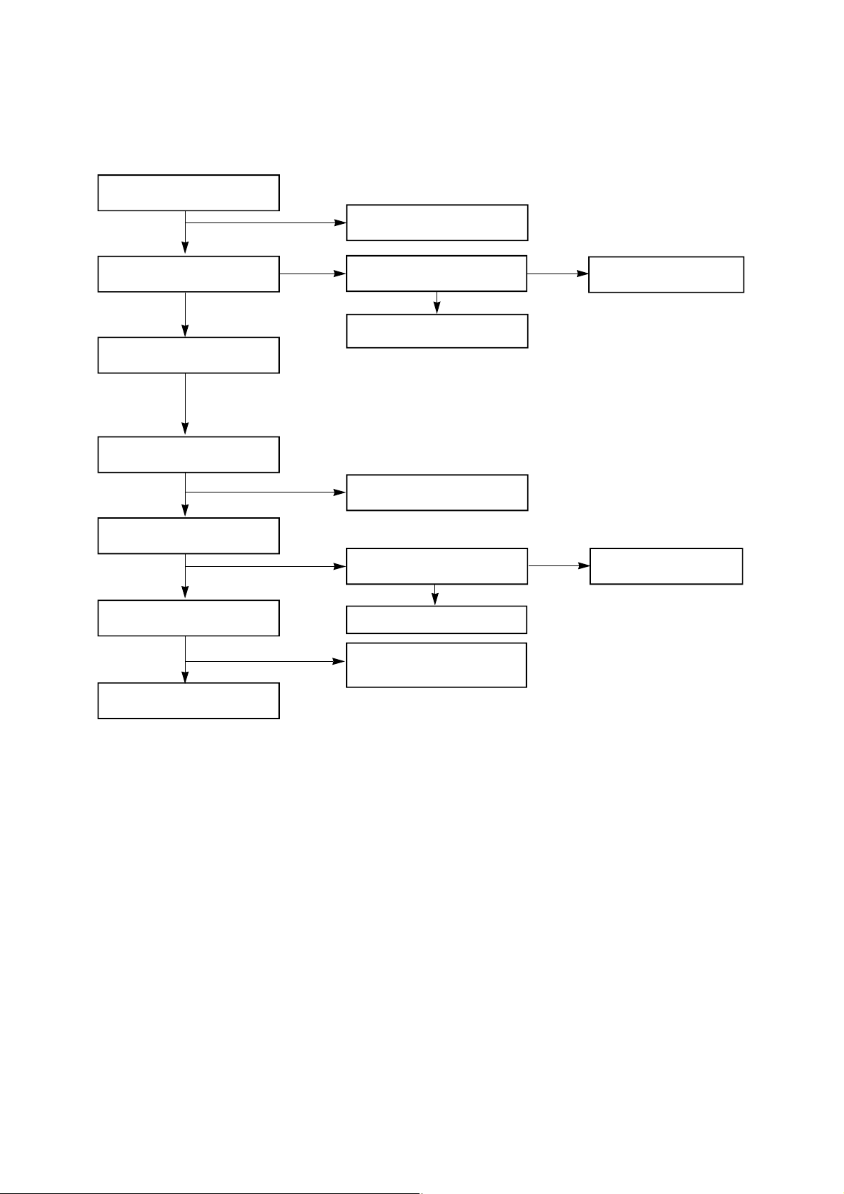
POWER CIRCUIT
Check the Fuse
YES
NO
Replace the Fuse
Check the DC output
of C715(+), C716(-)
YES
Check the DC 12V Input of
IC702
YES
Check the DC 6.2V
output of IC704
YES
Check the DC 12V
Output of IC703
YES
Check the "Collector# (5.6V)
of Q704 (CD FUNCTION)
NO
NO
NO
Check the power
YES
Replace the D701, D702,
703, 704
Check the Pattern of IC702
and IC704
Check the "High# of
IC703 pin4
YES
Replace the IC703
Refer to IC401
TROUBLESHOOTING
NO
Replace the Transformer
Check the "LOW# of
IC401 pin8
OK
- 2-9-
Page 14

MUTING CIRCUIT (MUTE)
Dose "High# appear at
Q701, Q751 "B#
YES
check the "LOW# Q701,
Q751, "C#
YES
MUTE
AUDIO ABNORMAL
Check the output of
IC701 Pin 2, 4
YES
Check the input of
IC701 pin7, 11
NO
NO
Refer to "IC203 Troubleshooting#
(ONLY Q201/Q251)
Check the "High# of Q702 "E#
YES
Replace the Q702
Replace the TR
NO
Check the speaker connector
NO
Refer to "IC301
Troubleshooting#
YES
Check the DC 10V of IC400
PIN24
YES
Check the DC 12V Output of
IC702
YES
Power check
NO
Check the FUNCTION input
terminal
- 2-10-
Page 15

FUNCTION MODE AUDIO ABNORMAL
TAPE
Check the signal input of IC400 pin 7, 28
Refer to "IC200 Troubleshooting#
CD TUNER
CHECK THE SIGNAL INPUT OF IC400 PIN 3, 4
Check the signal CN500 Pin 1, 3 or Refer
to "CD Troubleshooting#
IC301 TROUBLESHOOTING
AUX
Chekc the signal input of IC400, pin 1, 6
Check the signal input of JK400
Check the signal input of IC400 pin 2, 5
Refer to "IC102 Troubleshooting#
Check the power supplying IC301 Pin 17, 46, 90?
NO
YES
Check the "High# of IC301 pin26
NO
YES
Check the oscillation of X301
NO
YES
When power supplying to IC301 pin12.
(Low High)
NO
YES
Replace the IC301
Refer to "Power Circuit Troubleshooting#
Check the P-SENS
Replace the X301
Check the RESET circuit
- 2-11-
Page 16

IC203 TROUBLESHOOTING
Check the power supplying
to IC400 pin24
YES
Check the CLK Data of IC400 pin 21, 22
NO
Refer to "Power Circuit Troubleshooting#
YES
Check the CONTROLL function
NO
YES
END
FM (TUN101)
Check the 12V input of TUN101 B+ 6
YES
Check the "High# Voltage of TUN101 VT 5
NO
Replace the
IC400
Check the "GND# of IC103 Pin 7
Check the Data of IC301 Pin 9, 10
(CD TAPE FUNCTION)
Check the pattern
of (IC301, IC400)
Check the 12V of Q102 "E#
NO
YES
NO
YES
Replace the Q102
Refer to "IC301
Troubleshooting#
Refer to "Power Circuit
Trouble-shooting#
Refer to "IC103
Troubleshooting#
YES
Check the OSC waveform of TUN101 Pin 8
YES
Refer to "IC102 Troubleshooting#
Replace the TUN101
Replace the TUN101
- 2-12-
Page 17

IC102 TROUBLESHOOTING
Is power supplied to pin8
NO
YES
Check the waveform of Pin 20, 21
NO
YES
Check the output of Pin 16, 17
NO
YES
END
IC103 TROUBLESHOOTING
Check the power supplying to pin 17
NO
YES
Refer to "Power Circuit
Troubleshooting#
Check the FM(TUN101) & AM(L107)
NO
Replace the IC102
Check the "Low# of Pin 13
NO
YES
Replace the IC102
Refer to "Power Circuit
Troubleshooting#
Refer to "IC103
Troubleshooting#
Check the oscillation of X104
NO
YES
Check the waveform of CE, DI, DO, CLK
NO
YES
Is the normal ?
NO
YES
END
Replace the X104
Check the line or refer to "IC 301
Troubleshooting#
CE: Chip Enable
DI: Data Input(from u-com)
DO: Data Output(to u-com)
CLK: Tuner mode clock
Replace the IC103
- 2-13-
Page 18

AM COIL TROUBLESHOOTING
Check the "High# of L107 Pin 2
YES
Check the oscillation of L107 Pin 13
YES
Refer to "IC102 Troubleshooting#
Play
Check the VCC supplying to IC201 pin 4
YES
Check the signal output of IC201 pin 3, 6
YES
Check the "Low# of Q201, 251 "B#
NO
NO
NO
NO
Refer to "IC103 Troubleshooting#
Replace the L107
Refer to "Power Circuit Troubleshooting#
Check the Deck Mecha
NO
YES
Replace the Deck
Mecha.
Replace the IC201
- 2-14-
Page 19

REC (Q252, Q202 ON / R273, R223 High)
Check signal supplied to IC203 pin 2, 8?
NO
YES
Check the output of IC203 Pin3, 7
NO
YES
Check the "High# of IC203 pin6
NO
YES
Check the oscillation of L201 pin1, 3
NO
YES
Replace the DECK
Check the "Low# of Q202,
Q252 "B#
YES
Replace the Q202, Q252
Check the Vcc power of IC203 Pin6
Check the power or Refer to "IC203
Troubleshooting#
Check the power
supplying to C227(+)
NO
YES
NO
Refer to "IC203
Troubleshooting#
Refer to "Power Circuit
Troubleshooting#
Check the oscillation of
Q204, "E#
YES
Check the 0.6V of
Q205 "B#
YES
OK
- 2-15-
NO
NO
Check the 0.6V of
Q205 "B#
Check the IC401 pin12
or Replace the L203
Page 20

CD MAIN P.C. BOARD (SOLDER SIDE)
- 2-36-
Page 21

CD MAIN P.C. BOARD (COMPONENT SIDE)
- 2-37-
Page 22

POWER P.C. BOARD
- 2-38-
Page 23

INTERNAL BLOCK DIAGRAM OF ICs
BU1923F (IC 302)
Low Dropout Voltage Regulator
FEATURES
RDS / RBDS compatible FM receivers for American and European markets, car stereos, high-fidelity stereo
systems and components, and FM pagers.
EQIALENT CIRCUIT
- 2-39-
Page 24

Pin descriptions
LA1837 (IC 102)
Single-Chip Home stereo IC with Electronic Tuning Support
The LA1837 is a single-chip AM/FM IF and MPX IC that supports electronic tuning and was developed for
use in home stereo systems. It is optimal for use in automatic station selection systems that use the SD and
IF counting techniques.
Block Diagram
FM SD
ADJ
3 rd 5 th
DECODER
ANTI-BIRDIE
FM
- 2-40-
Page 25

LC72131 (IC 103)
AM/FM PLL Frequency Synthesizer
BA3126N (IC 201)
2-channel head switch for radio cassette recorders
BA3308 (IC203)
Dual preamplifier with ALC
APPLICATIONS
Stereo radio cassette recorders, cassette decks and home stereo systems and music centers
- 2-41-
Page 26

TDA7440D (IC 701)
TONE CONTROL DIGITALLY CONTROLLED AUDIO PROCESSOR
DESCRIPTION
The TDA7440D is a volume tone (bass and treble) balance (Left/Right) processor for quality audio
applications in Hi-Fi systems.
BLOCK DIAGRAM
- 2-42-
Page 27

BU2090F (IC401)
12-bit, serial IN, parallel OUT driver
APPLICATIONS
Radio casstte players, telephones, compact audio systems, car stereos, and others
- 2-43-
Page 28

FAN8039BD3 (IC 802)
5-CH MOTOR DIVER
DESCRIPTION
The FAN8039BD3 is a monolithic integrated circuit suitable for a 5-CH motor driver which drives the
tracking actuator, focus actuator, sled motor, tray motor, spindle motor of the DVDP/CAR-CD systems.
-
GND3
DO4
28
2 2
Level
Shift
10K
Level
Shift
2 2
1 32 4 5 6 7
1+
DO1-
DO
Pin Definitions
DO 4+
IN4
25 24 23 22
2627
IN1
REGVCC
VCC
Regulator
REB
PS
VREF
FIN
(GND)
VCC 1
211920 18
10K
RESX
PS
H
H
L
L
H
L
H
L
2.5V
FUNCTION
All Active
Reg. Only Deactive
Reg. Only Active
All Deactive
TSD
8109
REO
RESX
FIN
(GND)
GND1
+
IN3
10K10K
DO 3
2 2
Level
Shift
COMP
DO 3-
10K
11
REV
FWD
CTL
17
12
DO 5-
IN2
DO 5+
16 15
Level
Shift
10K
2 2
13 14
DO 2+
GND 2
Level
Shift
DO 2-
NOSymbolDescriptionNOSymbolDescription
1DO1-CH1 Drive Output (-)15GND2Power Ground1 (CH 2,3,5)
2DO1+CH1 Drive Output (+)16DO5+CH5 Drive Output (+)
3IN1CH1 Drive Input17DO5-CH5 Drive Output(-)
4REGVCCRegulator Supply Voltage18DO3-CH3 Drive Output(-)
5REBRegulator Output 19DO3+CH3 Drive Output (+)
6REORegulator Feedback Input20IN3CH3 Drive Input
7RESXRegulator Reset21VCC1Supply Voltage1(CH2,CH3,CH5)
8GND1Signal Ground22PSPower Save
9CTLCH5 Motor Speed Control23VREFBias Voltage
10FWDCH5 Forward Input24VCCSupply Voltage(CH1,CH4)
11REVCH5 Reverse Input25IN4CH4 Drive Input
12IN2CH2 Drive Input 26DO4+CH4 Drive Output (+)
13DO2+CH2 Drive Output (+)27DO4-CH4 Drive Output (-)
14DO2-CH2 Drive Output (-)28GND3Power Ground2 (CH 1,4)
- 2-44-
Page 29

KA78R33 (IC 803)
Low Dropout Voltage Regulator
DESCRIPTION
The KA78R33 is a low-dropout voltage regulator suitable for various electronic equipments. It provides
constant voltage power source with TO-220 4 lead full mold package. Dropout voltage of KA78R33 is
below 0.5V in full rated current(1A). This regulator has various function such as peak current protection,
thermal shut down, overvoltage protection and output disable function.
INTERNAL BLOCK DIAGRAM
1
Vin
Vdis
BLOCK DIAGRAM
XIN
XOUT
FMIN
THERMAL SHUTDOWN
BANDGAP REFERENCE
HIGH / LOW
4
1.4V
1
2
+
OUTPUT
ON / OFF
REFERENCE
DIVIDER
SWALLOW COUNTER
1/16. 1/17 4bits
OVERVOLTAGE
PROTECTION
-
+
SOA PROTECTION
CIRCUIT
-
SHORTCIRCUIT
PROTECTION
3
GND
Q1
PHASE DETECTOR
CHARGE PUMP
UNLOCK
DETECTOR
2
Vo
R1
R2
PD
AIN
AOUT
AMIN
VDD
VSS
12bits PROGRAMMABLE
DIVIDER
CE
DI
CL
D0
CCB
I/F
POWER
ON
RESET
DATA SHIFT REGISTER
LATCH
B01 B02 B03 B04 I01 I02
UNIVERSAL
COUNTER
IFIN
- 2-45-
Page 30

TDA7265 (IC701)
25+25W STEREO AMPLIFIER WITH MUTE & ST-BY
DESCRIPTION
The TDA7265 is class AB dual Audio power amplifer assembled in the Multiwatt package, specially
designed for high quality sound application as Hi-Fi music centers and stereo TV sets.
PIN CONNECTION (TOP View)
- 2-46-
Page 31

KIA7805, 7812API (IC 703, IC 782, IC 783)
LOW DROPOUT VOLTAGE REGULATOR
FEATURES
Suitable for C$MOS, TTL, the Other Digital IC!s Power Supply.
Internal Thermal Overload Protection.
Internal Short Circuit Circuit Current Limiting.
Output Current in Excess of 1A
Satisfies IEC$65 Specification. (International Electronical Commission.)
EQIALENT CIRCUIT
- 2-47-
Page 32

SECTION 4. SPEAKER SECTION
MODEL: LXS-220
850
862
851
853
852
859
864
855
854
863
856
857
861
858
- 4-1 -
Page 33

BLOCK DIAGRAM
NOTE: Warning
Parts that are shaded are critical With respect
to risk of fire or electrical shock.
2-16 2-17
Page 34

SHEMATICDIAGRAMS
MAIN SHEMATIC DIAGRAMS
NOTE: Warning
Parts that are shaded are critical With respect
to risk of fire or electrical shock.
2-182-19
Page 35

FRONT SHEMATIC DIAGRAMS
2-20 2-21
Page 36

TUNER & DECK SHEMATIC DIAGRAMS
2-22 2-23
Page 37

CDP SHEMATIC DIAGRAMS
2-24 2-25
Page 38

WIRING DIAGRAM
2-262-27
Page 39

PRINTED CIRCUIT DIAGRAMS
MAIN & TUNER P.C. BOARD (SOLDER SIDE)
2-282-29
Page 40

MAIN & TUNER P.C. BOARD (COMPONENT SIDE)
2-302-31
Page 41

FRONT P.C. BOARD (SOLDER SIDE)
2-322-33
Page 42

FRONT P.C. BOARD (COMPONENT SIDE)
2-342-35
Page 43

SECTION 3. EXPLODED VIEWS
CABINET AND MAIN FRAME SECTION
NOTE) Refer to !SECTION 4 REPLACEMENT
PARTS LIST" in order to look for the
part number of each part.
A26
257
A41
355
250
260
356
279
459
459
274
272
306
286
278
267
264
285
284
A43
454
454
454
A00
351
459 301
A46
454
311
310
451
450
304
454
450
304
302
459
451
A47
305
303
3-13-2
Page 44

TAPE DECK MECHANISM: AUTOSTOP DECK(OPTIONAL)
025
400
404
006
002
003
004
005
008
010
009
401
401
503
400
011
502
501
013
032
031
409
406
408
030
407
401
028
029
400
016
017
007
014
015
026
027
020
019
018
402
A01
023
024
403
505
021
022
405
504
3-3 3-4
Page 45

TAPE DECK MECHANISM: AUTOREVERSE DECK
025
400
404
006
002
003
004
005
008
508
507
010
009
401
401
503
400
011
409
502
501
013
406
410
032
038
031
039
034
035
036
400
016
017
037
506
007
014
015
026
027
040
028
029
020
019
018
402
A01
023
024
403
505
021
022
405
504
3-5 3-6
Page 46

CD MECHANISM
001
002
A01
429
004
003
429
026
430
012
430
430
012
012
430
012
013
017
A02
018
014
015
431
430
A03
020
011
3-7 3-8
 Loading...