

LG LWHD8008R Service Manual

website http://www.lgappliances.com
LG
LG
Room
Air Conditioner
SERVICE MANUAL
MODELS: LWHD8008R
CAUTION
• BEFORE SERVICING THE UNIT, READ THE SAFETY
PRECAUTIONS IN THIS MANUAL.
• ONLY FOR AUTHORIZED SERVICE PERSONNEL.

—2—
CONTENTS
1. PREFACE ...................................................................................................................................................3
1.1 FEATURES.....................................................................................................................................................3
1.2 SPECIFICATIONS .........................................................................................................................................3
1.3 LOCATIONS OF CONTROLS .......................................................................................................................4
1.4 SAFETY PRECAUTIONS ..............................................................................................................................4
1.5 INSULATION RESISTANCE TEST ................................................................................................................4
2. DISASSEMBLY INSTRUCTIONS ................................................................................................5
2.1 MECHANICAL PARTS ..................................................................................................................................5
2.1.1 FRONT GRILLE ....................................................................................................................................5
2.1.2 CABINET................................................................................................................................................5
2.1.3 CONTROL BOARD................................................................................................................................5
2.2 AIR HANDLING PARTS ................................................................................................................................6
2.2.1 AIR GUIDE UPPER ..............................................................................................................................6
2.2.2 ORIFICE, TURBO FAN AND FAN .........................................................................................................6
2.2.3 MOTOR ..................................................................................................................................................7
2.2.4 AIR GUIDE.............................................................................................................................................7
2.3 ELECTRICAL PARTS ....................................................................................................................................7
2.3.1 OVERLOAD PROTECTOR ...................................................................................................................7
2.3.2 COMPRESSOR .....................................................................................................................................8
2.3.3 CAPACITOR ..........................................................................................................................................8
2.3.4 THERMOSTAT .......................................................................................................................................8
2.3.5 ROTARY SWITCH..................................................................................................................................8
2.3.6 POWER CORD .....................................................................................................................................9
2.4 REFRIGERANT CYCLE ................................................................................................................................9
2.4.1 CONDENSER .......................................................................................................................................9
2.4.2 EVAPORATOR ....................................................................................................................................10
2.4.3 CAPILLARY TUBE ..............................................................................................................................10
3. INSTALLATION ....................................................................................................................................12
3.1 SELECT THE BEST LOCATION .................................................................................................................12
3.2 HOW TO INSTALL .......................................................................................................................................12
3.3 ELECTRICAL DATA .....................................................................................................................................15
4. TROUBLESHOOTING GUIDE ....................................................................................................
15
4.1 OUTSIDE DIMENSIONS..............................................................................................................................15
4.2 PIPING SYSTEM ........................................................................................................................................16
4.3 TROUBLESHOOTING GUIDE ....................................................................................................................17
5. CIRCUIT DIAGRAM ...........................................................................................................................22
6. EXPLODED VIEW ..............................................................................................................................23
7. SERVICE PARTS LIST ....................................................................................................................24
—3—
1. PREFACE
This service manual provides various service information, including the mechanical and electrical parts, etc.
This room air conditioner was manufactured and assembled under a strict quality control system.
The refrigerant is charged at the factory. Be sure to read the safety precautions prior to servicing the unit.
1.1 FEATURES
• DESIGNED FOR COOLING ONLY
• POWERFUL AND INCREDIBLE COOLING
• TOP-DOWN CHASSIS FOR THE SIMPLE INSTALLATION AND SERVICE
• BUILT-IN ADJUSTABLE THERMOSTAT
• WASHABLE ONE-TOUCH FILTER
• COMPACT SIZE
1.2 SPECIFICATIONS
MODELS
ITEMS
COOLING CAPACITY (BTU/h) 5,800
POWER SUPPLY (Phase, V, Hz) 1ø, 115V, 60HZ
INPUT (W) 600
OPERATING CURRENT (AMP.) 5.6
REFRIGERANT CONTROL CAPILLARY TUBE
REFRIGERANT CHARGE (R-22) 269g (9.5 oz)
INSIDE FAN TURBO FAN
OUTSIDE FAN PROPELLER FAN WITH SLINGER RING
AIR DISCHARGE 2-WAY (RIGHT AND LEFT)
CHASSIS TOP-DOWN
PROTECTOR
TEMPERATURE CONTROL THERMOSTAT
ROTARY SWITCH
FAN MOTOR 6 POLES, 16W
• OVERLOAD PROTECTOR FOR COMPRESSOR
• INTERNAL PROTECTOR FOR FAN MOTOR
5 STEP (LOW FAN, HIGH FAN, OFF, HIGH COOL, LOW COOL)
RAD-61A
1-1. PREFACE
This service manual provides various service information, including the mechanical and electrical parts, etc.
This room air conditioner was manufactured and assembled under a strict quality control system.
The refrigerant is charged at the factory. Be sure to read the safety precautions prior to servicing the unit.
1.1 FEATURES
• DESIGNED FOR COOLING ONLY
• POWERFUL AND INCREDIBLE COOLING
• TOP-DOWN CHASSIS FOR THE SIMPLE INSTALLATION AND SERVICE
• BUILT-IN ADJUSTABLE THERMOSTAT
• WASHABLE ONE-TOUCH FILTER
• COMPACT SIZE
1.2 SPECIFICATIONS
MODELS
ITEMS
COOLING CAPACITY (BTU/h) 5,100
POWER SUPPLY (Phase, V, Hz) 1ø, 115V, 60HZ
INPUT (W) 475
OPERATING CURRENT (AMP.) 4.4
REFRIGERANT CONTROL CAPILLARY TUBE
REFRIGERANT CHARGE (R-22) 280g (9.9 oz)
INSIDE FAN TURBO FAN
OUTSIDE FAN PROPELLER FAN WITH SLINGER RING
AIR DISCHARGE 2-WAY (RIGHT AND LEFT)
CHASSIS TOP-DOWN
PROTECTOR
TEMPERATURE CONTROL THERMOSTAT
ROTARY SWITCH
• OVERLOAD PROTECTOR FOR COMPRESSOR
• INTERNAL PROTECTOR FOR FAN MOTOR
5 STEP (LOW FAN, HIGH FAN, OFF, HIGH COOL, LOW COOL)
RADS-51B
FAN MOTOR 6 POLES, 16W
—3—
—4—
1.3 LOCATIONS OF CONTROLS
1.4 SAFETY PRECAUTIONS
1. When servicing, set the ROTARY SWITCH to
Off and unplug the power cord.
2. Observe the original lead dress.
If a short circuit is found, replace all parts which
have been overheated or damaged by the short circuit.
3. After servicing, make an insulation resistance test
to prevent the customer from being exposed to
shock hazards.
1.5
INSULATION RESISTANCE TEST
1. Unplug the power cord and connect a jumper
between 2 pins (black and white).
2. The grounding conductor (green or green and yellow) is to be open.
3. Measure the resistance value with an ohm meter
between the jumpered lead and each exposed
metallic part on the equipment at all position
[except Off] of the ROTARY SWITCH.
4. The value should be over 1 MΩ.
CAUTION : After switching the air conditioner from Cool to Off or Fan, wait at least 3 minutes before switching it
back to Cool.
Operation
High
Fan
Low
Fan
High
Cool
Off
Low
Cool
Thermostat
1
2
3
4
5
6
7
8
9
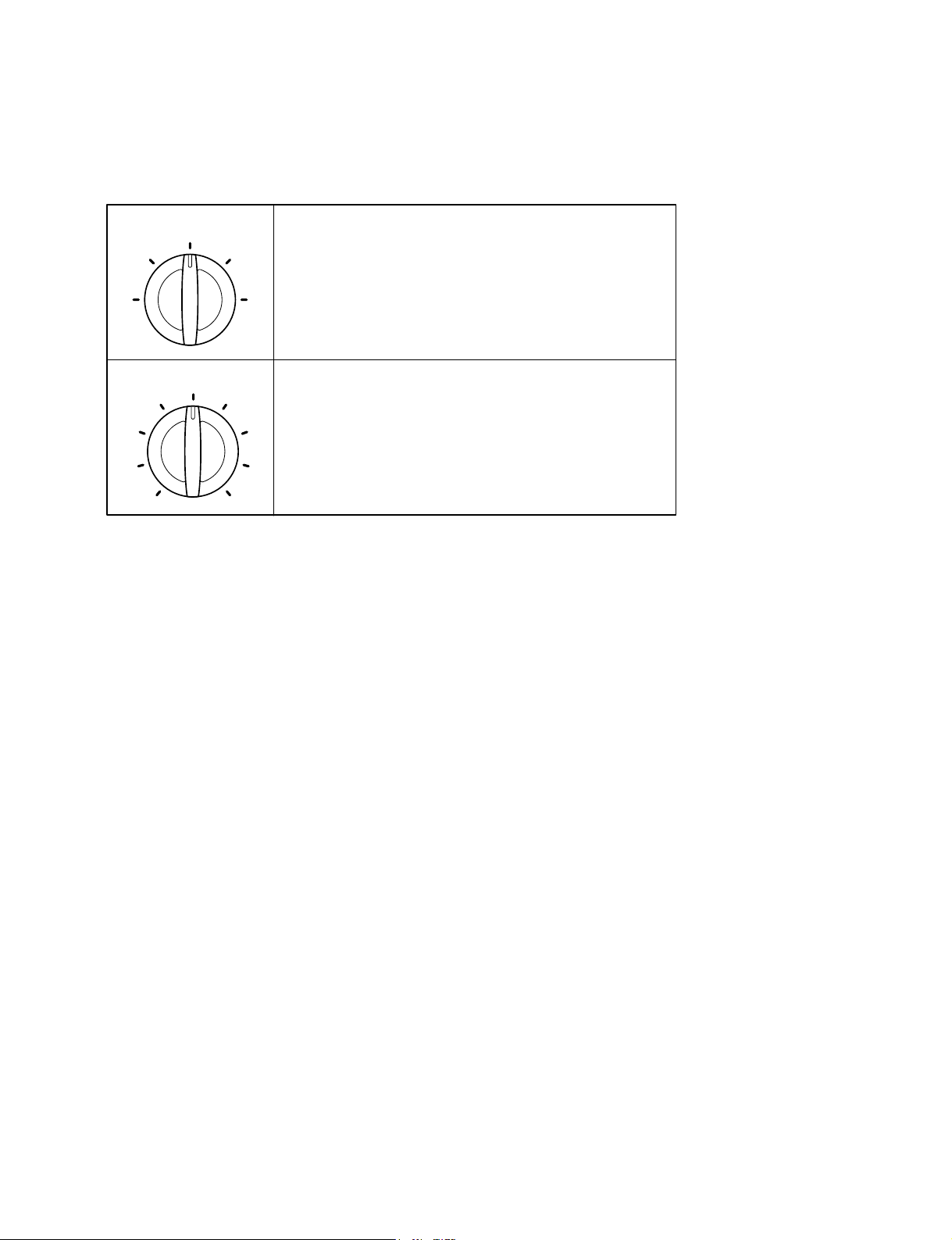
Off - Turns air conditioner off.
High Fan - High speed fan operation without cooling.
Low Fan - Low speed fan operation without cooling.
High Cool - Cooling with high speed fan operation.
Low Cool - Cooling with low speed fan operation.
This automatically controls the temperature of the indoor air.
Turn the knob so that arrow points to the larger marks for greater
cooling. Point the arrow to the smaller marks for more moderate
cooling.
(i.e. the higher the number, the greater the cooling)
—5—
2. DISASSEMBLY INSTRUCTIONS
2.1 MECHANICAL PARTS
2.1.1 FRONT GRILLE
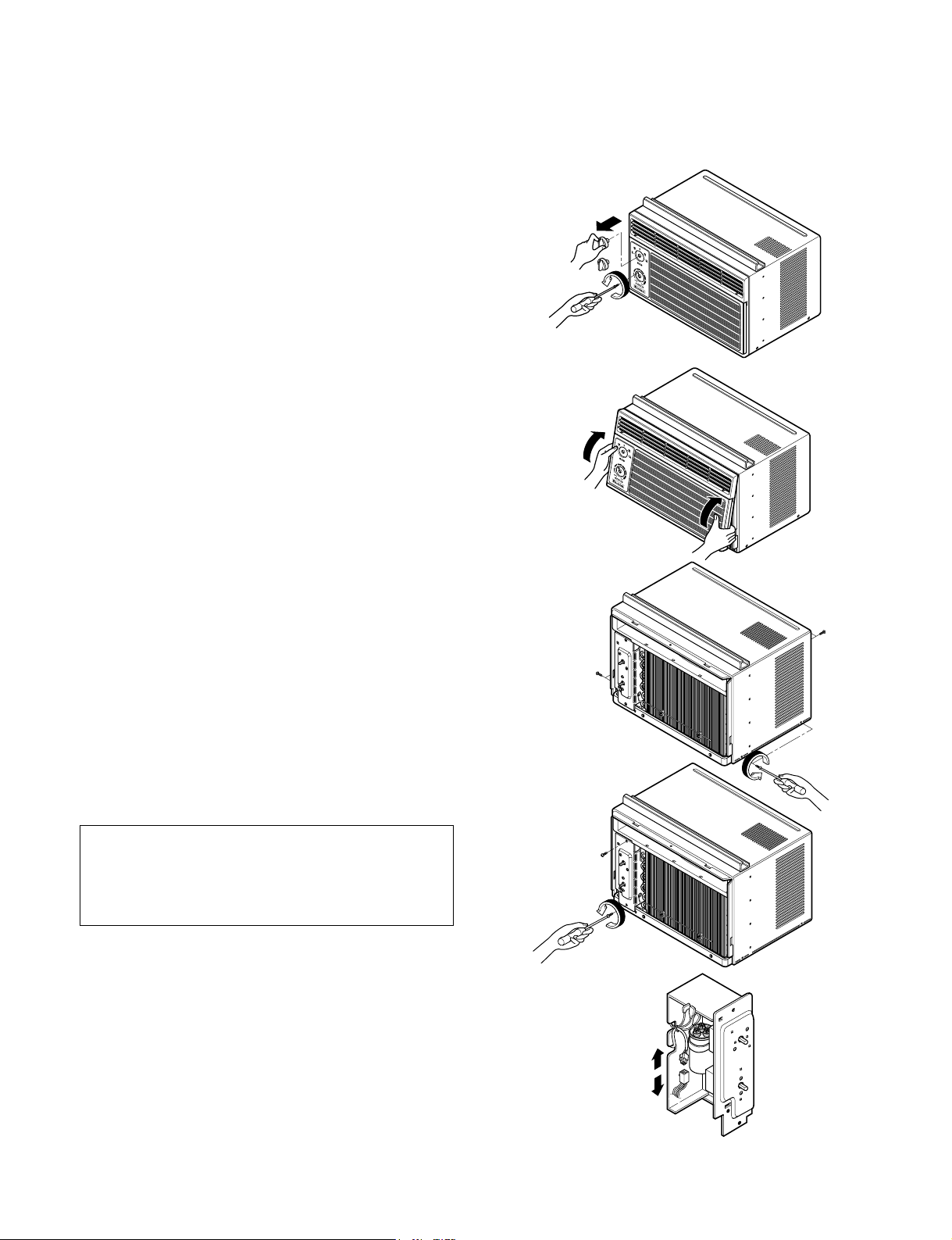
1. Disconnect the unit from source of power.
2. Remove the two knobs by pulling them off.
Using a screwdriver, remove the screw that
secures the front grille to control board.
(See Figure 1)
3. Push the front grille up from the bottom.
Pull the top of the front grille away from the
cabinet as the top tabs lift out of their slots.
(See Figure 2)
4. Replace the grille by placing the tabs in the slots
and push the grille until it snaps into place.
2.1.2 CABINET
1. Disconnect the unit from the power source.
2. Remove the front grille. (Refer to section 2.1.1)
3. Remove 9 screws that secure the cabinet to the
base pan and condenser. (See Figure 3)
4. Lift the cabinet from the unit.
5. Re-install by referring to the procedures above.
2.1.3 CONTROL BOARD
1. Disconnect the unit from the power source.
2. Remove the front grille. (Refer to Section 2.1.1)
3. Remove the cabinet. (Refer to Section 2.1.2)
4. Remove 2 screws that secure the control board to
base pan and air guide. (See Figure 4)
5. Pull the control board toward yourself.
6. Disconnect one housing terminal and 3 wires for
the fan motor and compressor. (See Figure 5)
7. Re-install components by referring to procedures
above. (Refer to wiring diagram on page 23 in this
manual or inside control board.)
Figure 1
Figure 2
Figure 3
Figure 4
Figure 5
NOTE : Controls, wires, and capacitor are now
accessible for servicing. Discharge the
capacitor before servicing. See step
2.3.3 on page 8 for procedures.
—6—
2.2 AIR HANDLING PARTS
2.2.1 AIR GUIDE UPPER
1. Disconnect the unit from the power source.
2. Remove the front grille. (Refer to Section 2.1.1)
3. Remove the cabinet. (Refer to Section 2.1.2)
4. Remove the control board.
(Refer to Section 2.1.3)
5. Remove 2 screws that secure the air guide upper
to air guide lower. (See Figure 6)
6. Lift air guide upper upward.
7. Re-install by referring to the procedures above.
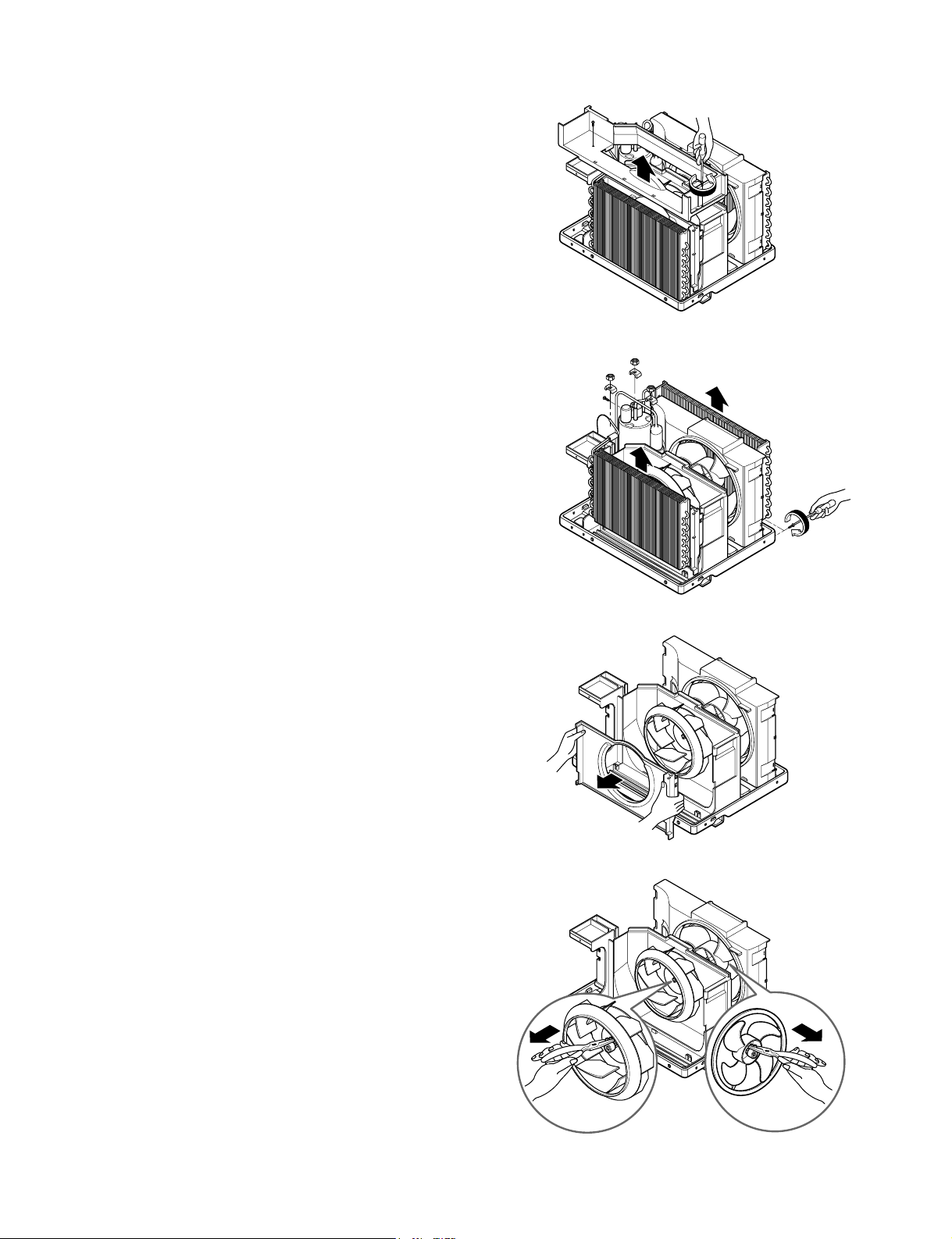
2.2.2 ORIFICE, TURBO FAN AND FAN
1. Disconnect the unit from the power source.
2. Remove the front grille. (Refer to Section 2.1.1)
3. Remove the cabinet. (Refer to Section 2.1.2)
4. Remove the control board.
(Refer to Section 2.1.3)
5. Remove the air guide upper.
(Refer to Section 2.2.1)
6. Remove 2 screws that secure the base pan to
condenser. (See Figure 7)
7. Remove screw that secures the shroud to
channel of condenser.
8. Press the snap area of shroud with your thumbs.
This allows you to remove it from the condenser.
9. Lift the compressor upward with the evaporator
and condenser. (See Figure 7)
10. Remove the orfice by pushing the snap area of
the air guide blower. (See Figure 8)
11. Remove the clamp springs which are clamped to
the boss of fan and turbo fan by hand plier. (See
Figure 9)
12. Pull the fan and turbo fan outward.
13. Remove the shroud.
14. Re-install by referring to the procedures above.
Figure 6
Figure 7
Figure 8
Figure 9
—7—
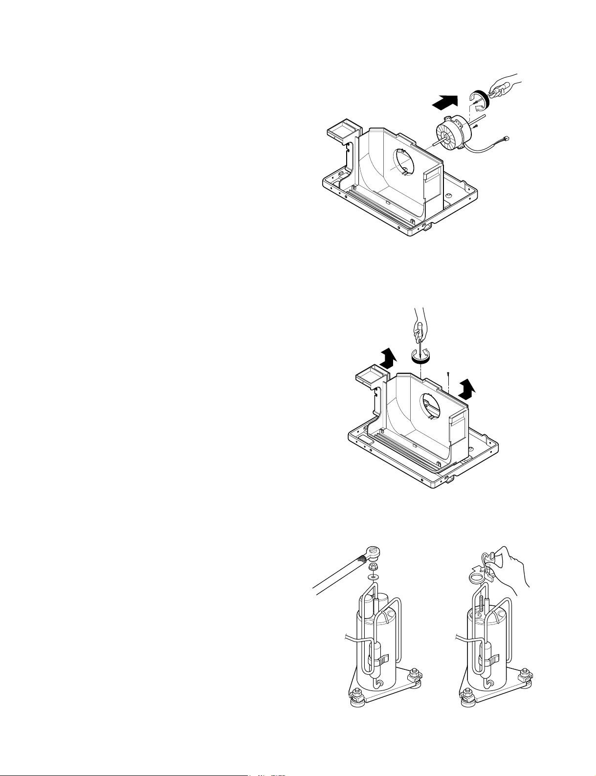
2.2.3 MOTOR
1. Disconnect the unit from the power source.
2. Remove the front grille. (Refer to Section 2.1.1)
3. Remove the cabinet. (Refer to Section 2.1.2)
4. Remove the control board.
(Refer to Section 2.1.3)
5. Remove the air guide upper.
(Refer to Section 2.2.1)
6.
Remove the compressor, turbo fan, fan and
shroud. (Refer to
Section
2.2.2)
7.
Remove 2 screws that secure the motor to the
motor. (See Figure 10)
8. Remove the motor.
9.
Re-install by referring to the procedures above.
2.2.4 AIR GUIDE
1. Disconnect the unit from the power source.
2. Remove the front grille. (Refer to Section 2.1.1)
3. Remove the cabinet. (Refer to Section 2.1.2)
4. Remove the control board.
(Refer to Section 2.1.3)
5. Remove the air guide upper.
(Refer to Section 2.2.1)
6.
Remove the compressor, turbo fan, fan and
shroud. (Refer to
Section
2.2.2)
7.
Remove the motor. (Refer to
Section
2.2.3)
8. Remove 2 screws that secure the air guide to the
base pan. (See Figure 11)
9. Push the air guide backward and lift it upward.
(See Figure 11)
10. Re-install by referring to the procedures above.
2.3 ELECTRICAL PARTS
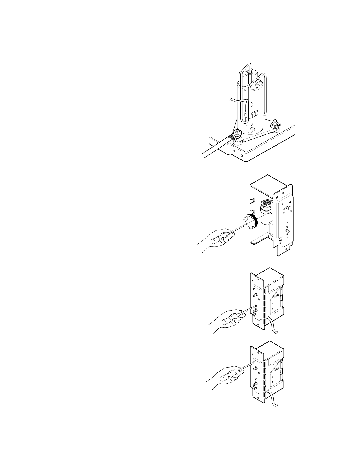
2.3.1 OVERLOAD PROTECTOR
1. Remove the front grille and cabinet.
(Refer to Section 2.1)
2. Remove the nut which fastens the terminal cover.
3. Remove the terminal cover.
4. Remove all the leads from the overload protector.
5. Remove the overload protector.
6. Re-install the components by referring to the
removal procedure above.
(See Figure 12 and 13)
Figure 10
Figure 12
Figure 13
Figure 11
—8—
2.3.2 COMPRESSOR
1. Remove the front grille and cabinet.
(Refer to Section 2.1)
2. Discharge the refrigerant by using a refrigerant
recovery system.
3. Remove the overload protector.
(Refer to Section 2.3.1)
4. After discharging the unit completely, unbrace the
suction and discharge pipes at the compressor
connections.
5. Remove 3 nuts which fasten the compressor.
6. Remove the compressor.
7. Re-install by referring to the removal procedure
above. (See Figure 14)
2.3.3 CAPACITOR
1. Remove the cabinet. (Refer to Section 2.1.2)
2. Remove the control board.
(Refer to Section 2.1.3)
3. Discharge the capacitor by placing a 20 KΩ
resistor across the capacitor terminals.
4. Remove the screw which fastens the capacitor
clamp.
5. Remove all the leads of capacitor terminals.
6. Re-install the components by referring to the
removal procedure above. (See Figure 15)
2.3.4 THERMOSTAT
1. Remove the cabinet. (Refer to Section 2.1.2)
2. Remove the control board.
(Refer to Section 2.1.3)
3. Remove 2 screws which fasten the thermostat.
4. Remove all the leads of the thermostat terminals.
5. Remove the thermostat.
6. Re-install the components by referring to the
removal procedure above. (See Figure 16)
2.3.5 ROTARY SWITCH
1. Remove the cabinet. (Refer to Section 2.1.2)
2. Remove the control board.
(Refer to Section 2.1.3)
3. Remove 2 screws which fasten the rotary switch.
4. Remove all the leads of the rotary switch
terminals.
5. Remove the rotary switch.
6. Re-install the components by referring to the
removal procedure above. (See Figure 17)
Figure 14
Figure 15
Figure 16
Figure 17
 Loading...