

LG LWHD2500ER, LW240CE, HBLG2504E, LW250CE Service Manual

website http://www.lgservice.com
LG
LG
Room
Air Conditioner
SERVICE MANUAL
MODELS: HBLG2504E
LW250CE, LW240CE
LWHD2500ER
CAUTION
• BEFORE SERVICING THE UNIT, READ THE SAFETY
PRECAUTIONS IN THIS MANUAL.
• ONLY FOR AUTHORIZED SERVICE PERSONNEL.

Air Conditioner Service Manual
TABLE OF CONTENTS
Safety Precautions..........................................................................................................................................3
Dimensions .....................................................................................................................................................5
Outside dimensions....................................................................................................................................5
Product Specifications ..................................................................................................................................6
Installation .......................................................................................................................................................7
Select the Best Location ...........................................................................................................................7
Installation Check.......................................................................................................................................7
How to Secure the Drain Pipe....................................................................................................................7
How to Install..............................................................................................................................................8
Cabinet Installation.....................................................................................................................................9
Operation ......................................................................................................................................................11
Function of Controls .................................................................................................................................11
Disassembly ..................................................................................................................................................12
Mechanical Parts......................................................................................................................................12
Air Handling Parts ....................................................................................................................................13
Electrical Parts .........................................................................................................................................14
Refrigerating Cycle...................................................................................................................................16
Schematic Diagram.......................................................................................................................................19
Electronic Control Device.........................................................................................................................19
Wiring Diagram.........................................................................................................................................20
Components Location ..............................................................................................................................21
Troubleshooting Guide.................................................................................................................................22
Piping System ..........................................................................................................................................22
Troubleshooting Guide .............................................................................................................................23
Electrical Parts Troubleshooting Guide ....................................................................................................25
Electric Parts ............................................................................................................................................29
Exploded View ..............................................................................................................................................35
Replacement Parts List ................................................................................................................................36
2 Room Air Conditioner
Safety Precautions
WARNING
CAUTION
WARNING
Safety Precautions
To prevent injury to the user or other people and property damage, the following instructions must
be followed.
■ Incorrect operation due to ignoring instruction will cause harm or damage. The seriousness is
classified by the following indications.
This symbol indicates the possibility of death or serious injury.
This symbol indicates the possibility of injury or damage to properties only.
■ Meanings of symbols used in this manual are as shown below.
Be sure not to do.
Be sure to follow the instruction.
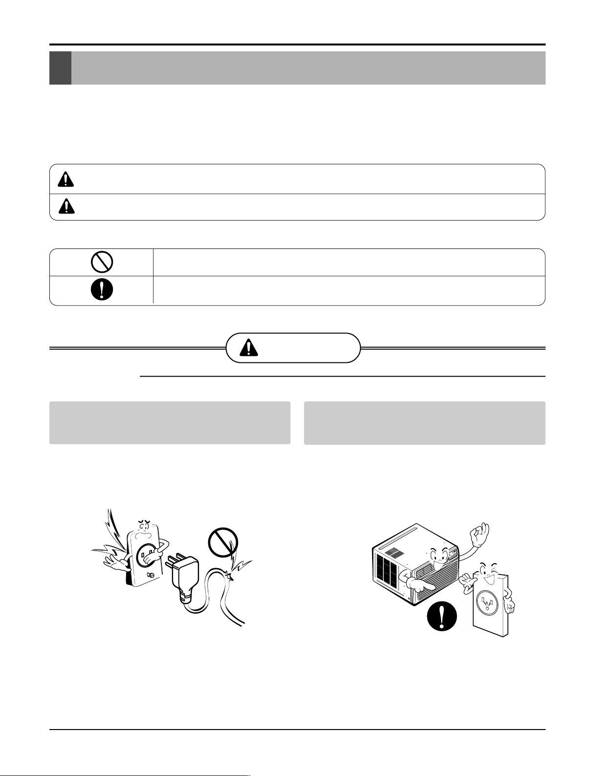
■ Installation
Do not use damaged power cord plugs, or a
loose socket.
• There is risk of fire or electric shock.
Always use the power plug and socket with
the ground terminal.
• There is risk of electric shock.
Service Manual 3
Safety Precautions
Sharp
edges
Gasolin
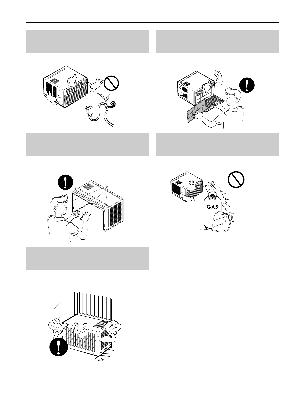
Do not modify or extend the power cord.
• There is risk or fire or electric shock.
Be cautious when unpacking and installing
the product.
• Sharp edges could cause injury. Be especially careful
of the case edges and the fins on the condenser and
evaporator.
Do not install, remove, or re-install the unit by
yourself(customer).
• There is risk of fire, electric shock, explosion, or injury.
Do not store or use flammable gas or combustibles near the air conditioner.
• There is risk of fire or failure of product.
Be sure the installation area does not deteriorate with age.
• If the base collapses, the air conditioner could fall with
it, causing property damage, product failure, and personal injury.
4 Room Air Conditioner
Dimensions
D
W
H
'
F
TIMER POWERMODE
TEMP
FAN
SPEED
F1 LOW
F2 MED
F3 HIGH
Dry Timer
Fan
Energy
Saver
Cool
NOTICE
Symbols Used in this Manual
This symbol alerts you to the risk of electric shock.
This symbol alerts you to hazards that could cause harm to the
air conditioner.
This symbol indicates special notes.
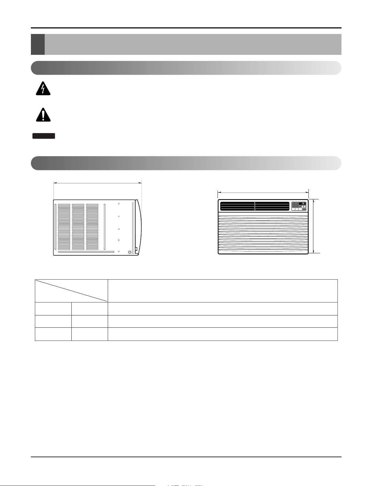
Outside Dimensions
Dimensions
Model
HBLG2504E, LW250CE, LW240CE, LWHD2500ER
Dimension
W mm(inch) 660(25 31/32)
H mm(inch) 449(17
D mm(inch) 721(28
11
/16)
13
/32)
Service Manual 5
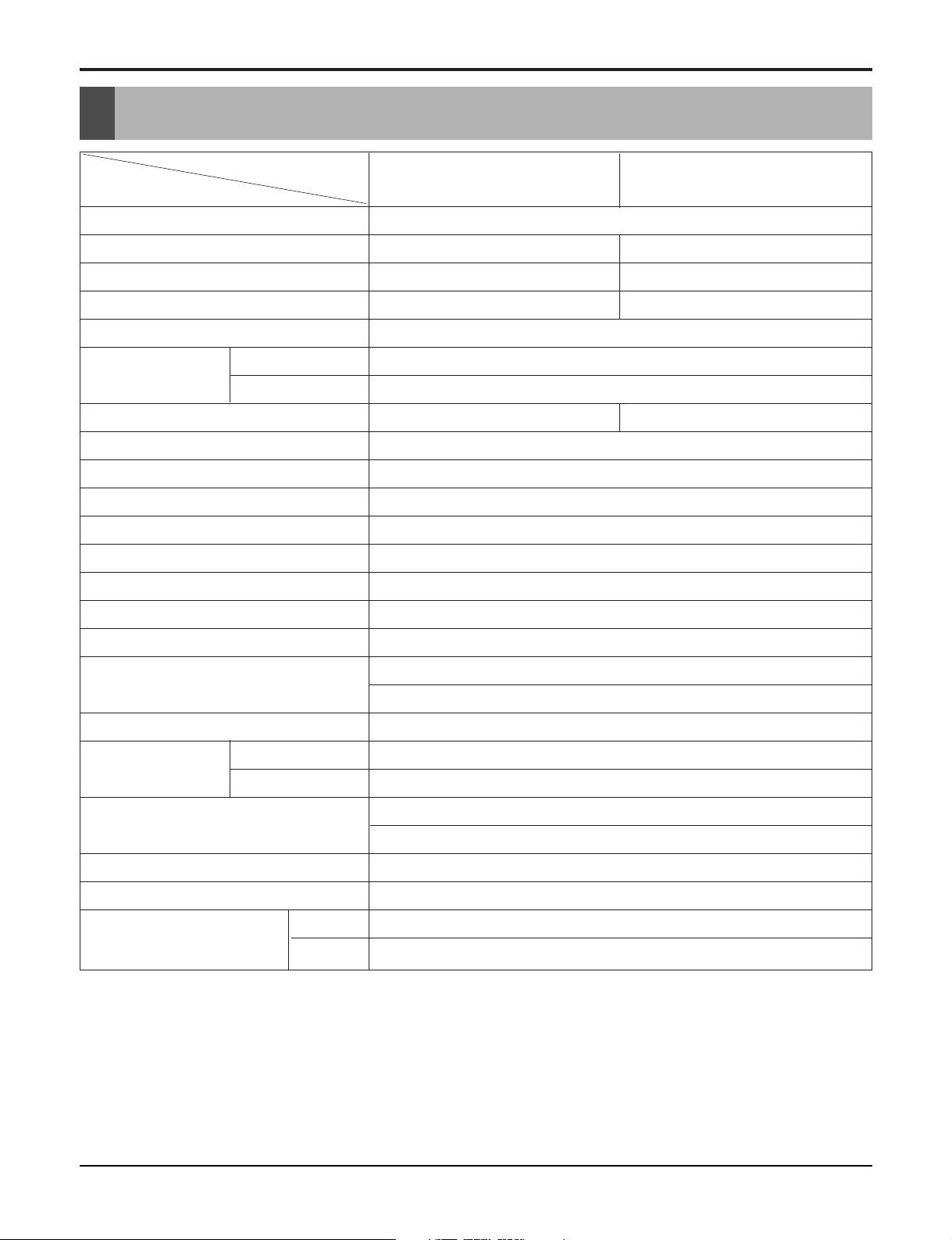
Specfications
Product Specifications
MODELS
ITEMS
POWER SUPPLY
COOLINGCAPACITY (BTU/h)
INPUT (W)
RUNNING CURRENT (A)
E.E.R (BTU/W.h)
OPERATING
CONDITION
REFRIGERANT (R-22) CHARGE
EVAPORATOR
CONDENSER
FAN, INDOOR
FAN, OUTDOOR
FAN SPEEDS, FAN/COOLING/HEATING
FAN MOTOR
OPERATION CONTROL
INDOOR (°C)
OUTDOOR (°C)
HBLG2504E, LW250CE,
LWHD2500ER
208/230V, 60Hz
24,500/25,000 23,150/23,600
2,600/2,660 2,450/2,500
13.0/12.0 13.2/12.2
9.4
26.7(DB)* 19.4(WB)**
35(DB)* 23.9(WB)**
1,080g(38.1 oz) 980g(34.6 oz)
3 ROW 12 STACKS
3 ROW 20 STACKS
TURBO FAN
PROPELLER TYPE FAN WITH SLINGER RING
3/3
6 POLES
REMOTE CONTROLLER
LW240CE
ROOM TEMP. CONTROL
AIR DIRECTION CONTROL
CONSTRUCTION
COMPRESSOR
PROTECTOR
FAN MOTOR
POWER CORD
DRAIN SYSTEM
NET WEIGHT (lbs/kg)
OUTSIDE DIMENSION (inch)
(W x H x D) (mm)
* DB : dry bulb
** WB : wet bulb
THERMISTOR
VERTICAL LOUVER (RIGHT & LEFT)
HORIZONTAL LOUVER (UP & DOWN)
SLIDE IN-OUT CHASSIS
OVERLOAD PROTECTOR
INTERNAL THERMAL PROTECTOR
3 WIRE WITH GROUDING
ATTACHMENT PLUG (CORD-CONNECTED TYPE)
DRAIN PIPE OR SPLASHED BY FAN SLINGER
128/58
25 31/32 x 1711/16 x 28 13/32
660 x 449 x 721
6 Room Air Conditioner
Installation
About 1/2"
Over 20"
HEAT
RADIATION
FENCE
AWNING
FOAM
COOLED
AIR
30-60"
Level
1/4 Bubble
Drain pipe
Drain cap
Fig. 4
Fig. 3
Fig. 2
DRAIN
PA N
DRAIN HOSE
Fig. 1
CABINET
SCREW
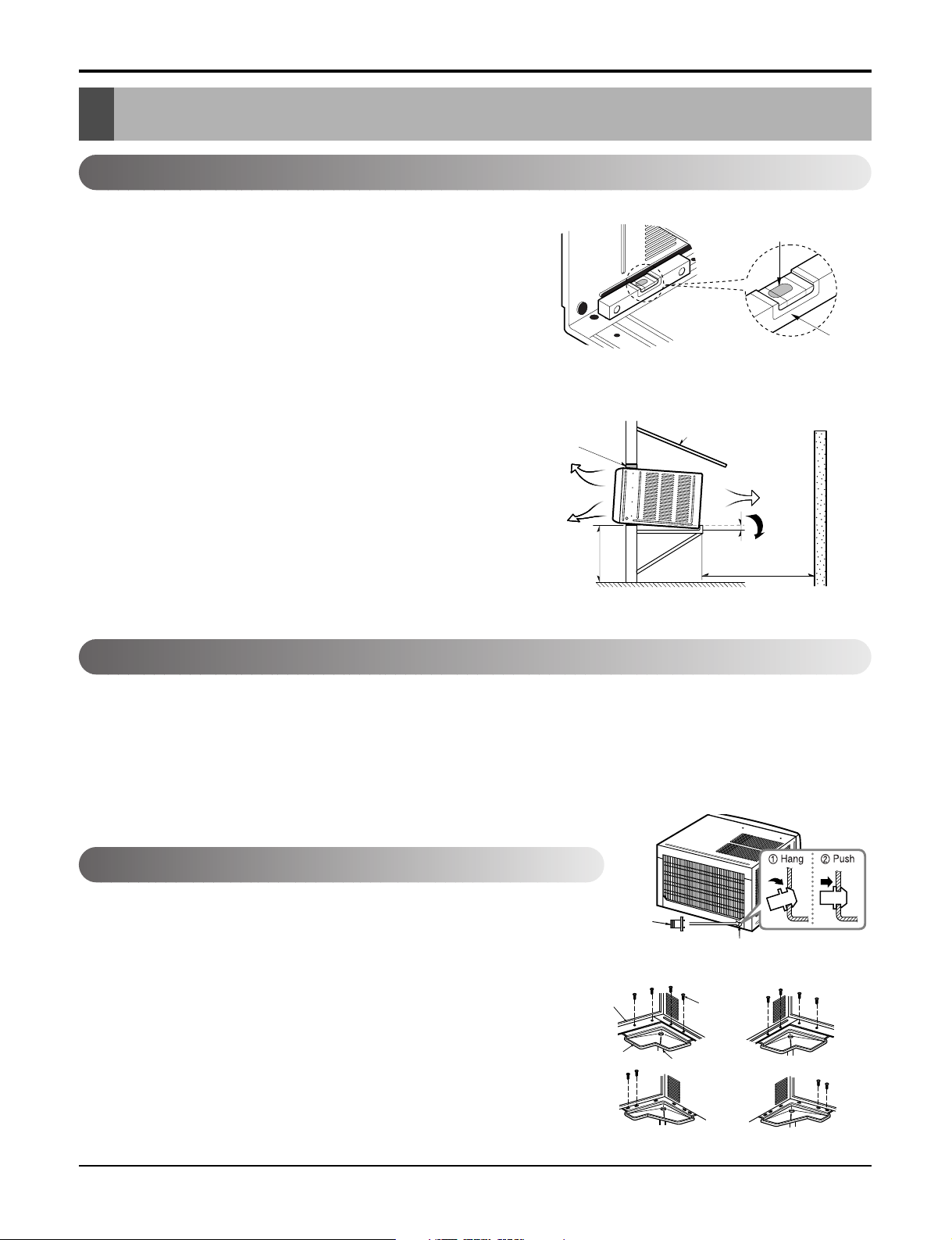
Select the Best Location
1. To avoid vibration and noise, make sure the unit is installed
securely and firmly.
2. Install the unit where the sunlight does not shine directly on the
unit.
If the unit receives direct sunlight, build an awning to shade the
cabinet.
3. There should be no obstacle, like a fence, within 20" which
might restrict heat radiation from the condenser.
4. To prevent reducing performance, install the unit so that louvers
of the cabinet are not blocked.
5. Install the unit a little obliquely outward not to leak the condensed water into the room (about 1/2" or 1/4 bubble with level).
6. Install the unit with its bottom portion 30~60" above the floor
level.
7. Stuff the foam between the top of the unit and the wall to prevent air and insects from getting into the room.
8. The power cord must be connected to an independent circuit.
The green wire must be grounded.
9. Connect the drain tube to the base pan hole in the rear side if
you need to drain (consult a dealer).
Plastic hose or equivalent may be connected to the drain tube.
Installation
Figure 1
Installation Check
The setting conditions must be checked prior to initial starting.
The following items are especially important check points when the installation is finished.
1. Grounding wire (Green or Green and Yellow) is provided in the power cord. The green wire must be grounded.
2. Connect to a single-outlet 15A circuit.
(or 20A circuit for Electric Heater Model)
3. To avoid vibration or noise, make sure the air conditioner is installed securely.
4 Avoid placing furniture or draperies in front of the air inlet and outlet.
How to Secure the Drain Pipe
In humid weather, excess water may cause the BASE PAN to overflow. To drain
the water, remove the DRAIN CAP and secure the DRAIN PIPE to the rear hole
of the BASE PAN. Press the drain pipe into the hole by pushing down and away
from the fins to avoid injury.
Optional
1. Install the drain pan over the corner of the cabinet where you removed
2. Connect the drain hose to the outlet located at the bottom of the drain
3. Select the most appropriate connection from among the following figures
the plug with 4 (or 2) screws.
pan. You can purchase the drain hose or tubing locally to satisfy your
particular needs. (Drain hose is not supplied).
(by considering the hole of the unit) to fit drain pan to your own unit.
Service Manual 7
Installation
29" to 41"
19" min.
Inner sill
Offset
Window
Sash
Sill
Exterior
Interior wall
26" min.
(Without frame curtain)
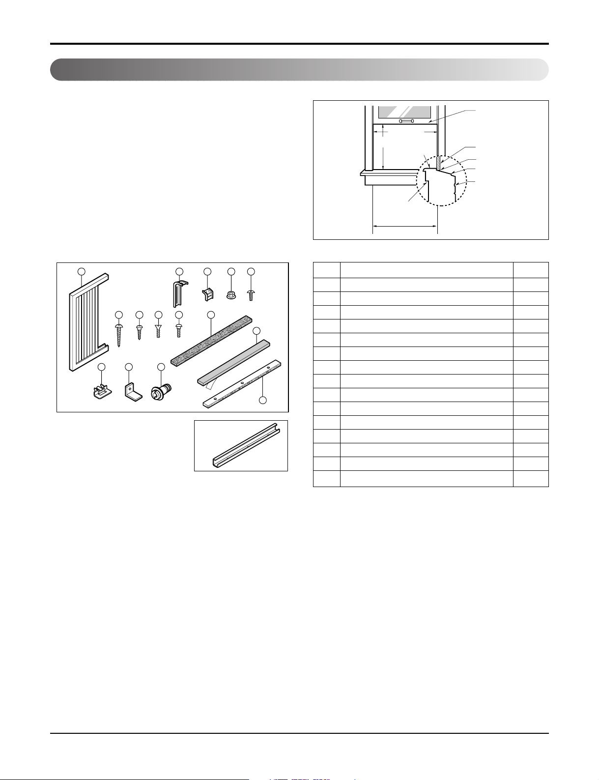
How to Install
When Using Installation Kits
1. Window Requirements
This unit is designed for installation in
standard double hung windows with actual opening
widths from 29" to 41".
The top and bottom window sash must open sufficiently to allow a clear vertical opening of 19" from
the bottom of the upper sash to the window stool.
2. Installation Kits Contents
1 2 3 4 5
6 7 8 9 10
14 12 13
■ Top retainer bar is in
the product package.
NO. NAME OF PARTS Q'TY
1 FRAME CURTAIN 2
2 SUPPORT BRACKET 2
3 SILL BRACKET 2
11
4 LOCK NUT 4
5 SCREW (TYPE A) 14
6 SCREW (TYPE B) 7
7 SCREW (TYPE C) 5
8 SCREW (TYPE D) 2
15
9 CARRIAGE BOLT 2
10 FOAM STRIP 1
11 FOAM SEAL 1
12 WINDOW LOCKING BRACKET 1
13 DRAIN PIPE 1
14 FRAME GUIDE 2
15 FOAM-PE 1
8 Room Air Conditioner
Cabinet Installation
NOTICE
6
Screw(Type B)
Front Angle
Sash track
Front angle
Window stool
Upper
Guide
3
9
2
4
Support
Bracket
Lock nut
Sill
Bracket
Carriage
Bolt
2
6
3
(Type B)
Cabinet
Track hole
Support
Bracket
Carriage bolt
and lock nut
Machine screw(Type D)
and lock nut
Outer edge
of window
sill
Sill bracket
15
11
Window sash
Upper Guide
Cabinet
Foam
-Seal
Frame curtain
Foam-PE
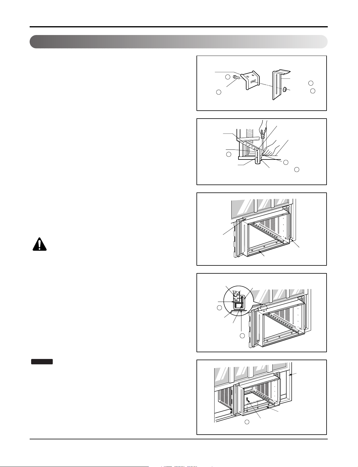
1. Open the window. Mark a line on the center of the window
stool between the side window stop moldings.
Loosely attach the sill bracket to the support bracket using
the carriage bolt and the lock nut.
Installation
2. Attach the sill bracket to the window sill using the screws
(Type B).
Carefully place the cabinet on the window stool and align the
center mark on the bottom front with the center line marked
window stool.
3. Using the M-screw and the lock nut, attach the support
bracket to the cabinet track hole. Use the first track hole
after the sill bracket on the outer edge of the window sill.
Tighten the carriage bolt and the lock nut. Be sure the cabinet slants outward.
CAUTION: Do not drill a hole in the
bottom pan. The unit is designed to
operate with approximately 1/2" of
4. Pull the bottom window sash down behind the Top retainer
water in bottom pan.
bar until they meet.
Figure 2
Figure 3
Figure 4
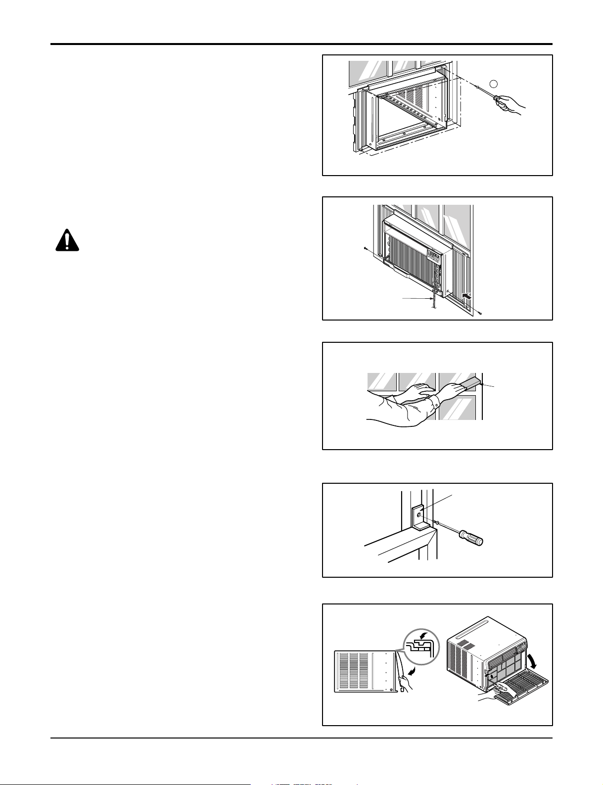
1. Do not pull the window sash down so tightly that the movement of Frame curtain is restricted. Attach the cabinet to the
window stool by driving the screws (Type B) through the
cabinet into window stool.
2. The cabinet should be installed with a very slight tilt
downward toward the outside.
Figure 5
Figure 6
Service Manual 9
Installation
(Type C)
7
Window locking
bracket
Foam-Strip
5. Pull each Frame curtain fully to each window sash
track, and pull the bottom window sash down behind
the Top retainer bar until it meets.
6. Attach each Frame curtain the window sash by using
screws (Type C). (See Fig. 7)
7. Slide the unit into the cabinet. (See Fig. 8)
CAUTION: For security purpose,
reinstall screws (Type A) at cabinet's
sides.
Figure 7
Screw
8. Cut the Foam-strip to the proper length and insert
between the upper window sash and the lower window sash. (See Fig. 9)
9. Attach the Window locking bracket with a screw
(Type C). (See Fig. 10)
10. Attach the front grille to the cabinet by inserting the
tabs on the grille into the tabs on the front of the cabinet. Push the grille in until it snaps into place. (See
Fig.11)
Power Cord
Figure 8
Figure 9
Figure 10
Screw
11. Lift the inlet grille and secure it with a screw (Type A)
through the front grille. (See Fig. 11)
12. Window installation of room air conditioner is now
completed. See ELECTRICAL DATA for attaching
power cord to electrical outlet.
10 Room Air Conditioner
Figure 11
6
6
Operation
Function of Controls
Operation
• Designed for COOLING ONLY.
• Powerful and quiet cooling.
• Slide-in and slide-out chassis for the simple instal-
lation and service.
• Low air-intake, top cooled-air discharge.
• Built-in adjustable Thermistor
• Washable one-touch filter
• Compact size
• Equipped with reliable and efficient rotary
compressor.
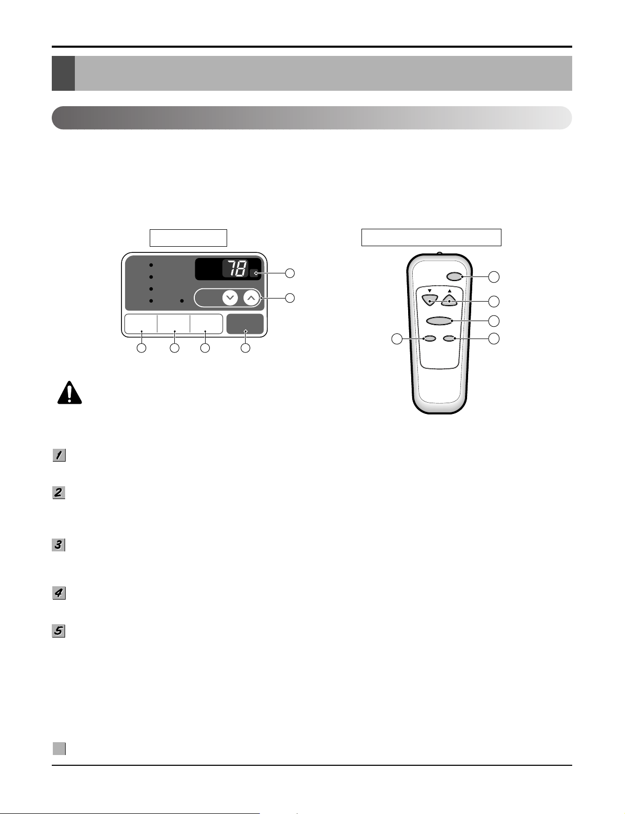
DISPLAY
Cool
Energy
Saver
Fan
Dry Timer
3 45
PRECAUTION:
F1 LOW
F2 MED
F3 HIGH
TEMP
TIMER POWERMODE
FAN
SPEED
The Remote Control unit will not
'
F
1
6
2
function properly if strong light strikes the sensor window
of the air conditioner or if there are obstacles between the
Remote Control unit and the air conditioner.
REMOTE CONTROL
Power
Temp
Fan Speed
Timer Mode
5
1
2
4
3
POWER BUTTON
To turn the air conditioner ON, push the button. To turn the air conditioner OFF, push the button again.
This button takes priority over any other buttons.
ROOM TEMPERATURE SETTING BUTTON
This button can automatically control the temperature of the room. The temperature can be set within a range of 60°F to
86°F by 1°F. (16°C to 30°C by 1°C)
Select the lower number for lower temperature of the room.
OPERATION MODE SELECTION BUTTON
Every time you push this button, it will shift among COOL, ENERGY SAVER, FAN and DRY.
-
Energy Saver: If Energy Save mode is selected, the fan stops when the compressor stops cooling.a
Approximately every 3 minutes the fan will turn on and check the room air to determine if cooling is needed.
FAN SPEED SELECTOR
Every time you push this button, it is set as follows.
(Hi [F3] ➔ Low [F1] ➔ Med [F2] ➔ Hi [F3] ➔ Low [F1] ➔...)
ON/OFF TIMER BUTTON
You can set the time when the unit will turn on or turn off automatically by pressing the timer button. If the unit is operating,
this button controls the time it will be turned off. If the unit is off state, this button controls the time it will start. Every time
you push this button, the remaining time will be set as follows.
- Stopping operation
(1Hour ➔ 2Hours ➔ 3Hours ➔ 4Hours ➔ 5Hours ➔ 6Hours ➔ 7Hours ➔ 8Hours ➔ 9Hours ➔ 10Hours ➔ 11Hours ➔
12Hours ➔ 0Hour ➔ 1Hour ➔ 2Hours ➔... )
- Starting operation
(1Hour ➔ 2Hours ➔ 3Hours ➔ 4Hours ➔ 5Hours ➔ 6Hours ➔ 7Hours ➔ 8Hours ➔ 9Hours ➔ 10Hours ➔ 11Hours ➔
12Hours ➔ off ➔ 1Hour ➔ 2Hours ➔ ... )
REMOCON SIGNAL RECEIVER
Service Manual 11
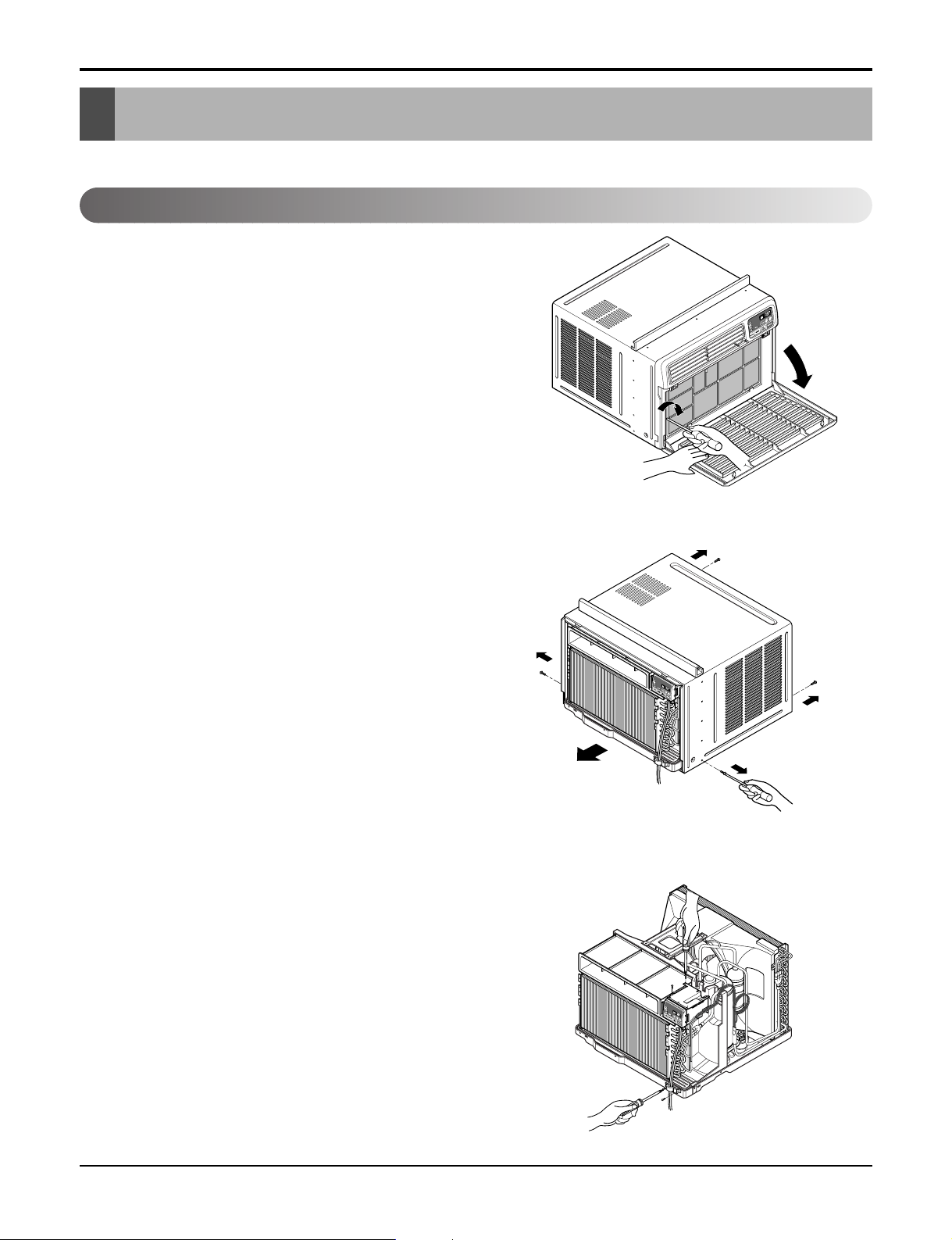
Disassembly
Disassembly
— Before the following disassembly, CONTROL BOX set to OFF and disconnect the power cord.
Mechanical Parts
1. Front Grille
1. Open the lnlet grille downward and remove the air filter.
2. Remove the screw that fastens the front grille.(See
Figure 13)
3. Pull the front grille from the right side.
4. Remove the front grille.(There are 4 hooks.)
5. Re-install the components by referring to the removal
procedure, above.
2. Cabinet
1. After disassembling the FRONT GRILLE, remove the 2
screws that fasten the cabinet at both sides.
2. Remove the 2 screws that fasten the cabinet at back.
3. Pull the base pan forward. (See Figure 14)
4. Remove the cabinet.
5. Re-install the components by referring to the removal
procedure, above.
Figure 13
3. Control Box
1. Remove the front grille. (Refer to section 1)
2. Remove the cabinet. (Refer to section 2)
3. Remove the 2 screws which fasten the power cord.
4. Disconnect the grounding screw from the evaporator
channel.
5. Remove the 1 screw that fastens the control box cover.
6. Remove the housing that connects PCB and motor
wire in the control box.
7. Disconnect the housing that connects Plazma Air
Purifier.(Optional)
8. Remove the screw at left cover of filter case and open
the cover to remove inner screw. (Optional)
9. Remove the nut that fastens the terminal cover.
10. Remove the terminal cover.
11. Remove all the leads from the overload protector.
12. Discharge the capacitor by placing a 20,000 ohm
resistor across the capacitor terminals.
13. Raise the control box upward completely.
(See Figure 15)
14. Re-install the components by referring to the removal
procedure, above.
(Refer to the wiring diagram found on page 22 in this
manual and on the control box.)
Figure 14
12 Room Air Conditioner
Figure 15Figure 15
 Loading...