

LG LW9226-AP, LW9228-AP Owner’s Manual

OWNER'S MANUAL
Network Camera &
Network Video Server
Please read this manual carefully before operating your set and retain it for future reference.
MODEL
LSW900/LSW901 series
LVW900/LVW901 series
LVW700/LVW701 series
LVS301/LVS311 series
LSW2010 series
LDW2010 series
LVS201 series
LW9226(I)/LW9228(I) series
LNP3700T series
LNP2800(I) series
1312 (V1.8)

Contents
Introduction .................................................................................... 3
Features Chart ..........................................................................................................3
Operation and settings .................................................................4
Before using the system .....................................................................................4
Recommended PC Requirements ...............................................................4
Accessing the LG IP device ...............................................................................5
LG Smart Web Viewer Overview ................................................................... 6
Conguration menu overview.......................................................................7
Conguring the LG Network Camera Device .......................................8
Accessing the Conguration menu ..........................................8
System settings......................................................................................8
Audio & Video settings ...................................................................11
Network settings ............................................................................... 20
User settings ......................................................................................... 24
Event settings ...................................................................................... 26
OSD Menu Setup (LSW900/LSW901/LVW700/LVW701/
LVW900/LVW901/LDW2010/LSW2010 series) ................ 29
General Operation ............................................................................ 31
Exposure settings .............................................................................. 31
White Balance settings...................................................................33
Day/Night settings ........................................................................... 33
3D-DNR setting ...................................................................................34
Privacy setting ..................................................................................... 34
Special menu settings .................................................................... 35
Reset setting ......................................................................................... 36
OSD Menu Setup (LW9226/LW9228/ LW9228I/ LW9226I/
LNP3700T/LNP2800/LNP2800I series) .................................. 37
Auto Tracking .......................................................................................41
General operation ............................................................................. 42
Camera menu settings...................................................................42
PAN/TILT Settings .............................................................................. 48
OSD Settings ........................................................................................ 50
LANGUAGE Setting...........................................................................51
RESET Setting ....................................................................................... 52
Reference .................................................................................... 53
Troubleshooting ...................................................................................................53
Open source software notice ...................................................................... 56
Specications ......................................................................................................... 57
2

Introduction
The LG Network Camera is designed to use on an Ethernet network and must be assigned an IP address to make it accessible.
This manual contains instructions on how to install and manage the LG Network Camera in your networking environment. Some knowledge of
networking environments would be beneficial to the reader.
Should you require any technical assistance, please contact authorized service center.
Features Chart
This table shows the differences between the models.
Item LSW900 LSW901 LVW700 LVW701 LVW900 LVW901 LSW2010 LDW2010
VA No Yes No Yes No Yes No No
PTZ Yes Yes No No No No No No
PRESET Yes Yes No No No No No No
Fan Fail Notification Yes Yes No No Yes Yes No No
WDR (OSD) Yes Yes Yes Yes Yes Yes No No
Item LVS201 LVS301 LVS311 LW9226(I) LW9228(I) LNP3700T LNP2800(I)
VA No No Ye s No No No No
PTZ Yes Yes Yes Yes Yes Yes Yes
PRESET Yes Yes Yes Yes Yes Yes Yes
Fan Fail Notification No No No No No No No
WDR (OSD) No No No Yes Yes Ye s Yes
Introduction 3

Operation and settings
Before using the system
• Before using the LG IP device make sure the connections are
correct and verify whether proper power supply is used.
• Check the connections of the LG IP device for the correct
conditions.
• Check that the LG IP device is(are) connected to the network and
that power is supplied.
• Once the connections are made you need to install the LG client
program to the PC from which you want to access the device.
The LG Smart Web Viewer program is automatically installed when
you connect the LG IP device.
The LG Ipsolute VMS and the LG Smart Web Viewer program are
the network program of the LG Video Server and the LG IP cameras.
• To view streaming video in Internet Explorer, set your browser
to allow ActiveX controls. If you find this message “This website
wants to install the following add-on: ‘IPCam_Streamer.cab’ from ‘LG
ELECTRONICS INC’”, Click the yellow bar and install LG Smart Web
Viewer Program on your computer.
• The Layouts and the Live view pages may differ with different OS
(Operating Systems) and Web Browsers.
• Care needs to be taken not to run any other applications when the
Client Program is running as it may cause memory shortage.
Recommended PC Requirements
The LG IP device can be used with most standard operating systems
and browsers.
Items Requirements
Operating System
CPU Intel Core2 Quard Q6700 (2.66 GHz) or above
Web Browser
DirectX DirectX 9.0 or above
Memory 2 GB or above RAM
Graphics Card 256 MB or above Video RAM
Resolution 2040 x 1536 (with 32 bit color) or higher
Windows XP Professional,
Windows VISTA, Windows 7
Microsoft Internet Explorer above the
version 6.0 and below the version 8.0.
4 Operation and settings

Accessing the LG IP device
You can access the LG IP device by following the below steps.
1. Install LG Ipsolute VMS Program
2. Discover the LG IP device using the IP Utility
The IP Utility can automatically discover and display LG IP
devices on your network. The IP Utility shows the MAC address,
IP address, Model name and so on.
Note:
The computer running the IP Utility must be on the same network segment (physical subnet) as the LG IP device.
2.1 Run the IP Utility program.
2.2 Click the [Search] button or select the [Search] option
in the Device search menu.
After a few seconds the found LG IP devices gets displayed in the IP Utility window.
3. Logging in to the LG Smart Web Viewer
The LG Smart Web Viewer can be used with most web
browsers. The recommended browser is Internet Explorer with
Windows.
3.1 Run the IP Utility and find the LG IP devices.
3.2 When the LG IP devices appear in the IP Utility window,
double-click IP address or right click on the same IP
address and select “Connect to Web Page” to start the
LG Smart Web Viewer. When accessing the LG Smart
Web Viewer, the authentication dialog appears on the
screen.
3.3 Enter the user name and password. (Note that the
default administrator user name and password are
“admin”.)
3.4 Click the [OK] button and then the LG Smart Web
Viewer is displayed in your browser.
Notes:
• You can also access the LG Smart Web Viewer as shown
below.
3.1 Start your Web browser.
3.2 Enter the IP address of the LG IP device in the address
bar of the browse.
3.3 Enter the user name and password set by the administrator.
3.4 Click the [OK] button and then the LG Smart Web
Viewer is displayed in your browser.
• The LG Smart Web Viewer needs more time to display it
according to the network conditions.
• If the login window is not displayed, check the pop-up
blocker. If you set the pop-up blocker, the login window is
not displayed. You must allow the pop-ups.
• If you connect the LG Smart Web Viewer for the first time,
the Security Warning window is displayed to install the LG
Smart Web Viewer program. You must install the LG Smart
Web Viewer program for using the LG IP device.
• If your computer or network is protected by a proxy or firewall, the proxy or firewall settings can prevent the LG Smart
Web Viewer program. Change the proxy or firewall settings
to activate the LG Smart Web Viewer program.
Operation and settings 5
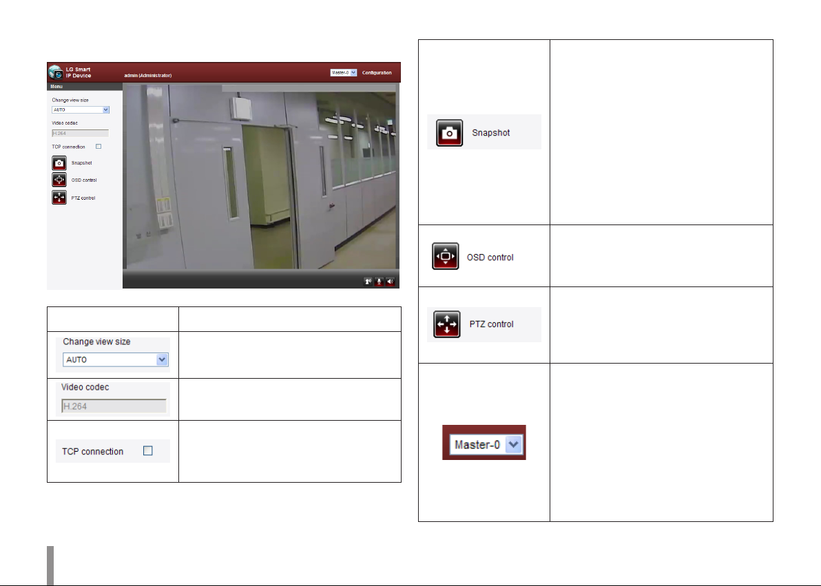
LG Smart Web Viewer Overview
Item Description
Select the video image size from the dropdown list.
The initial view size is set to AUTO.
Displays the current video codec of the
selected video stream (Master or Slave).
Check this option as the network
connection type (TCP or UDP). If you check
it, the client connects to the server using
TCP connection.
Click to save the current image in JPEG
format on your computer.
1. Click the [Snapshot] button and then
the Snapshot window is displayed.
2. Click the [Save] button in the Snapshot
window.
3. Enter the file name (JPEG format) and
select the folder to save it.
4. Click the [Save] button to confirm it.
5. Click the [Close] button in the
Snapshot window to close it.
Displays the Camera OSD control window.
Use these buttons to setup the Camera.
This button does not appear on the screen
if the login is other than the administrator.
Displays the PTZ control window. Use
these buttons to control the PTZ unit.
This button is not displayed with normal or
anonymous user. (The function depends
on the model.)
Select the video stream. From the Live
view drop-down list, select the desired
video image source between [Master-0]
and [Slave-0].
Note:
Master and Slave are output video streams.
You can set the stream configurations
independently for either Master or Slave
stream. This would facilitate the user to set
the live view at his comfort.
6 Operation and settings

Provides all the necessary tools for setting
up the device to your requirements. The
user will need administrator level to do
this.
Note:
If you want to exit the Configuration menu,
select one of the video stream in the Live
view drop-down list.
Displays the current surveillance live
screen. You can monitor the camera image
on the live view window of the LG Smart
Web Viewer.
Click this button to connect or disconnect
the audio communication between the LG
IP device and the connected PC.
(Color icon: On, Gray scale icon: Off.)
Click this button to switch the microphone
off and on for the computer.
(Color icon: On, Gray scale icon: Off.)
Click this button to switch the sound off
and on, for the speaker of the computer.
(Color icon: On, Gray scale icon: Off.)
Configuration menu overview
The following table shows the list of menu items.
The configuration images are different from each model.
Main Menu Sub Menu Note
Version
Date & Time
System
Audio & Video
Network
User Basic
Maintenance
Log & Report
Language
Camera
Stream
Audio Option
PTZ protocol Option
Preset Option
Motion detect
Auto Tracking Option
Basic
RTP stream
TCP/IP
DDNS
IP filtering
SNMP
Operation and settings 7

Event schedule
Event
Event server
Sensor & Relay Option
Fan Option
Configuring the LG Network Camera Device
The features and options of the LG IP camera are configured through
the Configuration menu.
Only administrator-level users have permission to access the
Configuration menu.
System settings
Version
Displays the current version of Firmware, Hardware, Software and Web
Client.
Accessing the Configuration menu
Click the [Configuration] button to display the LG Smart Web Viewer
configuration window.
Warning
The Configuration setup should be made by qualified service
personnel or system installers.
Date & Time
8 Operation and settings
Time zone
Set the time difference from GMT in the area where the IP device
is installed. Select the time zone in the area where the IP device is
installed from the drop down list.
Time mode
> Synchronize with NTP Server: Select if you want to synchronize
the IP device’s date and time with those of the time server
called NTP (Network Time Protocol). Specify the NTP server’s
name. Click the [Test] button for connection test to the server.
> Synchronize with personal computer: Select if you want to
synchronize the IP device’s date and time with your computer.
> Synchronize manually: Select if you want to set the IP device’s
date and time manually. Select the year, month and date by
clicking the calendar button. Set hour, minutes and seconds in
the edit boxes.
Notes:
• When system reboot after time setting, time of system
could be delayed. If you set the time correctly, set the
[Synchronize with NTP server] option.
• Refer to NTP configuration as operation system of the
Recording Server when the Recording Server use recording
function and NTP server.
Server time
> Server time: Displays the current date and time of the IP device.
• Save: Click this button to confirm the settings.
Maintenance
System reboot
Click the [Reboot] button to restart the IP device. It takes some minutes
for the IP device to start again.
Restore and backup
> Backup: To take a backup all of the settings. If necessary, it
make possible to return to a backuped configuration.
1. Click the [Backup] button.
2. Click the [Save] button.
3. Follow the instructions on the browser to specify the folder.
4. Click the [Save] button to save the settings.
> Restore:
1. Click the [Browse] button.
2. Find and open the file in which the configuration setting
data is stored.
3. Click the [Restore] button and the system settings will be
restored and reboot the system.
Operation and settings 9
Notes:
• Backup and Restore can happen on IP device having the
same version of firmware. This feature is not intended for
multi-configurations or for firmware upgrades.
• [Backup] function is allowed in HTTP protocol but not in
HTTPS protocol.
Firmware
> Upgrade
1. Click the [Browse] button.
2. Find and open the firmware file.
3. Click the [Upgrade] button to update the firmware.
Note:
When you upgrade the system, it may take some minutes to
be done. Do not close the browser while the upgrade is in
progress. If you close the browser, it may cause a malfunction.
You should wait until the confirmation window is displayed.
When the upgrade is finished, the confirmation window will be
displayed.
> Initialize: The [Initialize] button should be used with caution.
Clicking it will return all of the IP device’s settings to the factory
default values. (Except for the Network settings, PTZ Protocol
and Preset settings. The option depends on the model.)
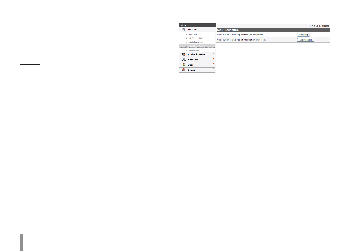
Log & Report
Log & Report status
The System log provides a summary of the status of the IP device. The
unit records the data of the software activity in a file.
> View Log: Click this button to display the system log
information.
- Download: Click this button to see the log information of
system.
> View report: Click this button to display the report of the
system.
- Download: Click this button to see the report information
of system.
Note :
The downloaded file is a UNIX type. If you open the file in Microsoft
Notepad, it will display the text as if the file contained no line breaks at
all.
10 Operation and settings

Language
Language list
Select a language for the LG Smart Web Viewer configuration menu
and information display.
• Save: Click this button to confirm the settings.
Audio & Video settings
Camera
Preview
You can preview the camera image on the preview window.
General
> Contrast: Edit the contrast value from 0 to 100. Selecting 100
provides the image with the highest contrast.
> Brightness: Edit the brightness of the camera. It is brighter
when a large value is selected and it is darker when a small
value is selected.
> Standard: Displays the video standard of the camera.
> Hue: Edit the video Hue of the camera from 0 to 100.
• Save: Click this button to confirm the settings.
• Default: Click this button to restore the IP device back to original
factory settings.
Operation and settings 11
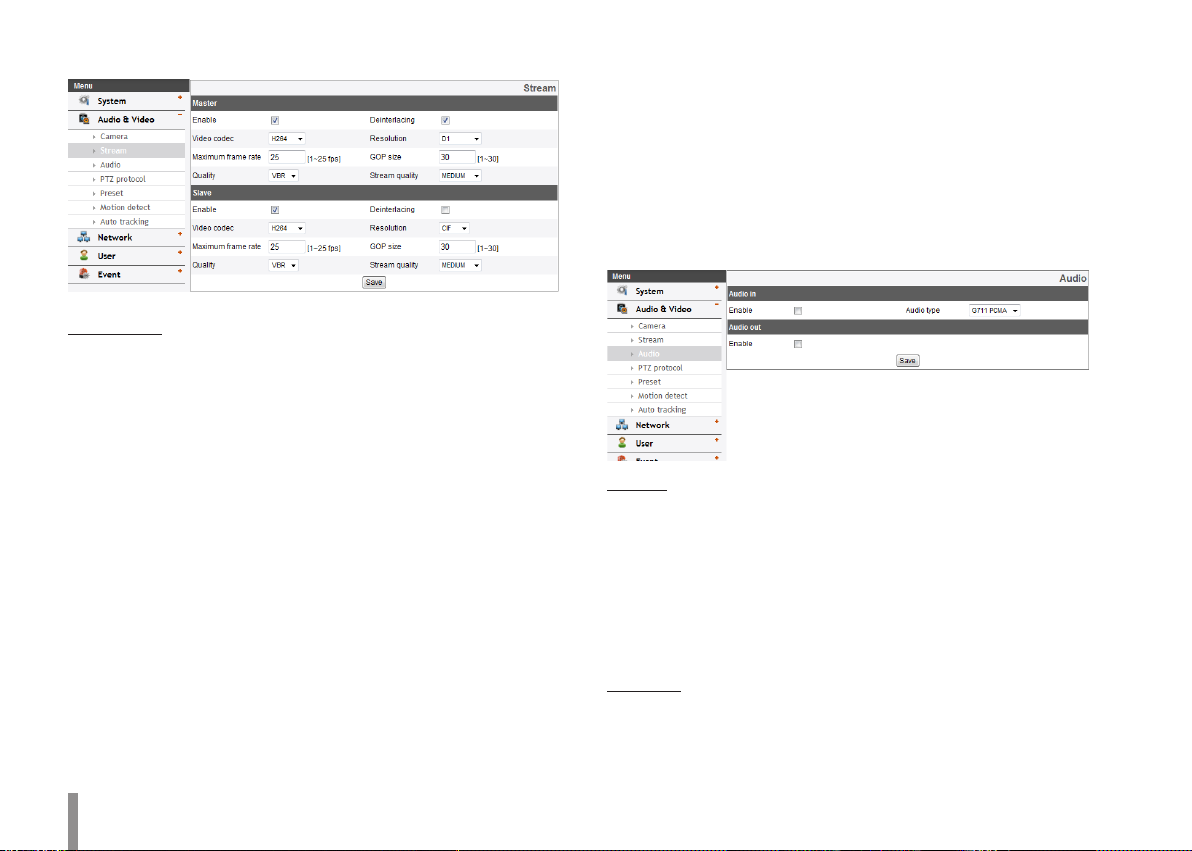
Stream
Master/Slave
> Enable: Click to activate the stream function.
> Deinterlacing: Click to activate the deinterlacing function.
> Video codec: Select the video mode (Codec) from the drop
down list. The viewer can choose between MJPEG and H.264.
> Resolution: Select the output image size of the camera.
> Maximum frame rate: Set the frame rate of the image.
> GOP size: It means “Group of Pictures”. The higher the GOP, the
better is the video quality of the camera. Edit the value of GOP
from 1 to 30. This setting is valid for H.264 video format only.
> Quality: Select the Quality.
- VBR: The bit rate may vary depending on the complexity of
the video to meet the selected quality.
- CBR: The video quality may vary in order to preserve a
constant bit rate.
> Stream quality: If the [Quality] option set to VBR, this option is
displayed. Select the stream quality from the drop down box,
the camera supports five types. (Highest, High, Medium, Low
and Lowest)
> Bit rate: If the [Quality] option set to CBR, this option is
displayed. Edit the bit rate value from 256 kbps to 10 240 kbps.
Note:
If the ‘Bit rate’ is configured too low with high resolution, the
actual frame rate will decrease because of narrow bandwidth.
So you need to set or change the ‘Bit rate’ to high value.
• Save: Click this button to confirm the settings.
Audio (Option)
Audio In
> Enable: Click the check box if you want to send the audio from
the microphone input connector.
Note:
The Clients connected to the IP device remain unaffected with
additional changes made in the setting.
> Audio type: Select the codec when you send the audio from
the microphone input connector.
Audio Out
> Enable: Click the check box to output the audio from the
speaker.
• Save: Click this button to confirm the settings.
12 Operation and settings
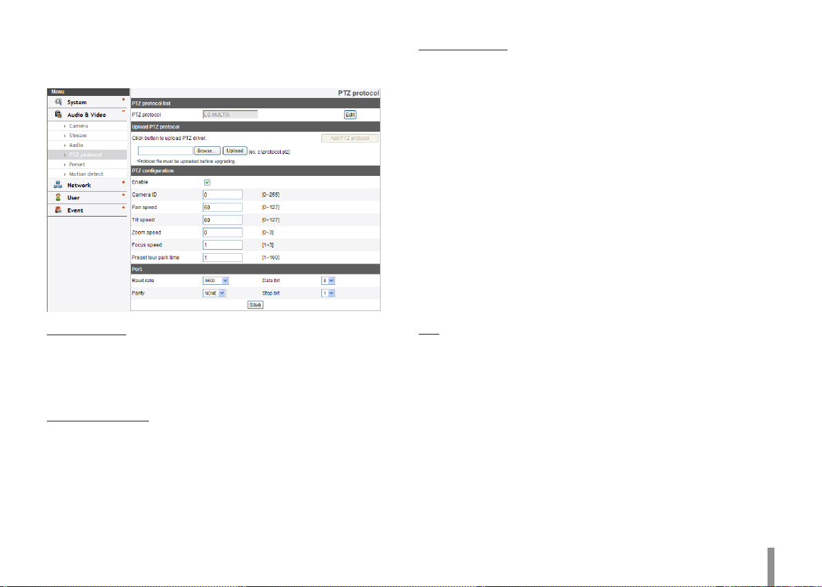
PTZ protocol (Option)
Allows the user to configure different PTZ controls by using different
PTZ protocols.
PTZ protocol list
> PTZ protocol: Displays the selected PTZ protocol.
> Edit: Click to display the PTZ protocol window. Select the PTZ
protocol and then click the [Save] button. If you want to delete
the protocol, click the [Remove] button.
Upload PTZ protocol
Follow the instructions below to upload PTZ protocol.
1. Click the [Browse] button, find and open the file and then click
[Upload] button.
2. Click the [Add PTZ protocol] button and then the PTZ protocol
will be added.
PTZ configuration
> Enable: Click to use the PTZ protocol.
> Camera ID: Enter the PTZ device ID. Make the same ID as the
PTZ Device.
> Pan speed: Enter the panning speed of the PTZ device in the
edit box. Default value for the LG Multix Protocol is 60 and
ranges from 0 to 127.
> Tilt speed: Enter the tilting speed of the PTZ device in the edit
box. Default value for the LG Multix Protocol is 60 and ranges
from 0 to 127.
> Zoom speed: Enter the zoom speed of the PTZ device to view
the object close or at a distance. Default value for the LG Multix
protocol is 1 and ranges from 0 to 3.
> Focus speed: Enter the focus speed of the PTZ device to focus
an object clearly near or far. Default value for the LG Multix
protocol is 1 and ranges from 1 to 3.
> Preset tour park time: Enter the parking time.
Port
> Baud rate: Select the desired speed of communication
between the IP device and the PTZ Device. Confirm selected
parameter to the baud rate of the IP device.
> Data bit: Set the number of the data bits for RS-422/RS-485
communication.
> Parity: Select the desired parameter. The parity bit, added to the
data, to perform parity check.
> Stop bit: Enter the desired parameter. The stop bit, added to
the last of data, in asynchronous communication.
• Save: Click this button to confirm the settings.
Operation and settings 13
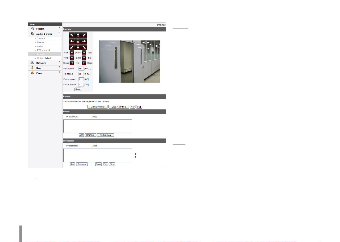
Preset (Option)
Preview
You can see the settings screen from the preview window.
1. Move the camera to the point you want by using the arrow
buttons.
2. Adjust the zoom, focus or iris options.
3. Set the Pan, Tilt, Zoom or Focus speed options.
4. Click the [Save] button to confirm the settings.
Pattern
You can activate the camera in a repeating pattern. The pattern is
programmed by recording your manual pan, tilt, and zoom operations.
The camera stores the movements you performed in memory.
> To record the pattern
1. Click the [Start recording] button to start the pattern
recording.
2. Move the camera through the desired movement.
3. Click the [Stop recording] button to stop the pattern
recording.
Note:
The available total time of pattern is different depending on
the connected PTZ device and operation.
> To play the pattern
1. Click the [Play] button to play the programmed pattern.
2. Click the [Stop] button to stop playing.
Preset
Displays the registered preset position.
• Add: Click to add a preset position.
1. Click the [Add] button.
2. Select the preset index number.
3. Enter the preset alias.
4. Click the [Save] button.
5. Repeat the steps 1 to 4 to add other positions.
Note:
If you set the HOME position, check the [Set home position]
option.
14 Operation and settings
• Remove: Click to delete the preset position.
1. Select the preset from the list.
2. Click the [Remove] button. The preset will be deleted.
• Go to preset: Move to the preset position.
1. Select the preset from the list.
2. Click the [Go to preset]. The camera will be moved to the
selected preset.
Preset tour
A preset tour is composed of a group of preset positions that the
operator can link together in a sequence.
> To tour the preset positions
1. Choose the preset in the [Preset].
2. Click the [Add] button in the [Preset tour].
3. Repeat the steps 1 to 2 to add another preset.
4. Click the [Save] button to confirm the preset tour.
5. Click the [Play] button to start the preset tour.
6. Click the [Stop] button to stop the preset tour.
Note:
If you control the PTZ or OSD, the preset tour will be stopped.
> Remove: Click this button to delete the selected preset in the
[Preset tour].
=============================================
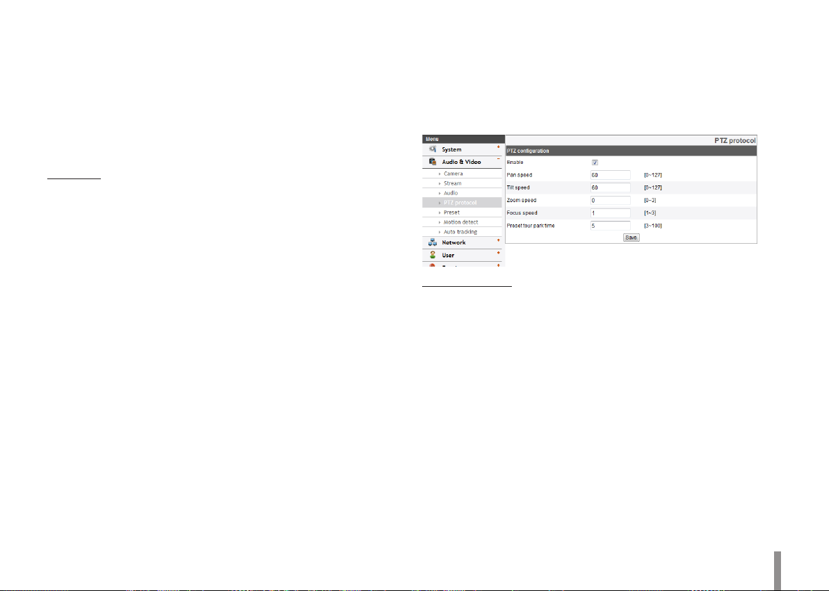
PTZ protocol (LW9228/LW9226/LW9228I/LW9226I/LNP3700T/
LNP2800/LNP2800I models only)
Allows the user to configure different PTZ controls by using different
PTZ protocols.
PTZ configuration
> Enable: Click to use the PTZ protocol.
> Pan speed: Enter the panning speed of the PTZ device in the
edit box. Default value for the LG Multix Protocol is 60 and
ranges from 0 to 127.
> Tilt speed: Enter the tilting speed of the PTZ device in the edit
box. Default value for the LG Multix Protocol is 60 and ranges
from 0 to 127.
> Zoom speed: Enter the zoom speed of the PTZ device to view
the object close or at a distance. Default value for the LG Multix
protocol is 1 and ranges from 0 to 3.
> Focus speed: Enter the focus speed of the PTZ device to focus
an object clearly near or far. Default value for the LG Multix
protocol is 1 and ranges from 1 to 3.
> Preset tour park time: Enter the parking time.
• Save: Click this button to confirm the settings.
Operation and settings 15

Preset
(LW9228/LW9226/LW9228I/LW9226I/LNP3700T/LNP2800/
LNP2800I models only)
Note:
While configuring PATTERN/PRESET/GROUP TOUR/AUTO PAN, turn off
Auto Tracking feature temporarily.
Preview
You can see the settings screen from the preview window.
1. Move the camera to the point you want by using the arrow buttons.
2. Adjust the zoom, focus or iris options.
3. Set the Pan, Tilt, Zoom or Focus speed options.
4. Click the [Save] button to confirm the settings.
Pattern
You can activate the camera in a repeating pattern. The pattern is
programmed by recording your manual pan, tilt, and zoom operations.
The camera stores the movements you performed in memory.
LNP3700T/LNP2800/LNP2800I series are supported pattern recording
up to 4. (LW9226/LW9228 series do not need to select a pattern index.)
» To record the pattern
1. Enter the pattern number you wish to register.
2. Click the [Start recording] button to start the pattern recording.
3. Move the camera through the desired movement.
4. Click the [Stop recording] button to stop the pattern recording.
Note:
The available total time of pattern differs depending on connected PTZ
device and operation.
» To play the pattern
1. Enter the pattern number you wish to register.
2. Click the [Play] button to play the programmed pattern.
3. Click the [Stop] button to stop playing.
Preset
Preset position is the function to register camera monitoring positions
(preset positions) associated with position numbers. By entering the
position numbers, you can move cameras to the preset positions.
» To register preset position
1. Enter the preset number you wish to register.
16 Operation and settings

2. Move the camera to a point you wish.
3. Click the [Add] button.
4. Repeat the steps 1 to 3 to add other positions.
» To remove the preset position
1. Enter the memorized preset index number.
2. Click the [Remove] button. The preset will be deleted.
» Changing a picture in a preset position
1. Enter the memorized preset index number.
2. Click the [Go to preset] button. The camera moves to the
preset position and the picture of the camera in that position
appears on the monitor.
Preset tour
A preset tour is composed of a group of preset positions that the
operator can link together in a sequence.
1. Click the [Play] button to start the preset tour.
2. Click the [Stop] button to stop the preset tour.
Note:
If you control the PTZ, the preset tour will be stopped.
Preset group tour
You can create a group using preset positions that are registered
already.
» To set the group
1. Enter the group number in the [Group index] option.
2. Enter the preset index number in the [Preset index] option.
3. Click the [Add] button.
4. Repeat the steps 2 to 3 to add other preset index number.
5. Repeat the steps 1 to 4 to set the other group index.
» To remove the preset index from the group
1. Enter the group number in the [Group index] option.
2. Enter the preset index number in the [Preset index] option.
3. Click the [Remove] button.
4. Repeat the steps 2 to 3 to remove other preset index number.
5. Repeat the stpes 1 to 4 to set the other group index.
» To tour the group
1. Enter the group number in the [Group index] option.
2. Click the [Play] button to start the group tour.
3. Click the [Stop] button to stop the group tour.
» To delete a group
1. Enter the group number in the [Group index] option.
2. Click the [Clear] button. The group will be deleted.
Auto pan
You can play the camera with auto pan function.
» To set the Auto Pan position
1. Enter the index number you wish to register.
2. Move the camera to the desired point.
3. Click the [Add] button.
4. Repeat the steps 1 to 3 to add other index number. You can set
the Auto pan index number up to 8.
» To play the auto pan
1. Click the [Play] button to start the Auto Pan function.
2. Click the [Stop] button to stop the Auto Pan function.
Note:
If you click the [CLEAR] button, all of Auto pan position will be deleted.
================================================
Operation and settings 17
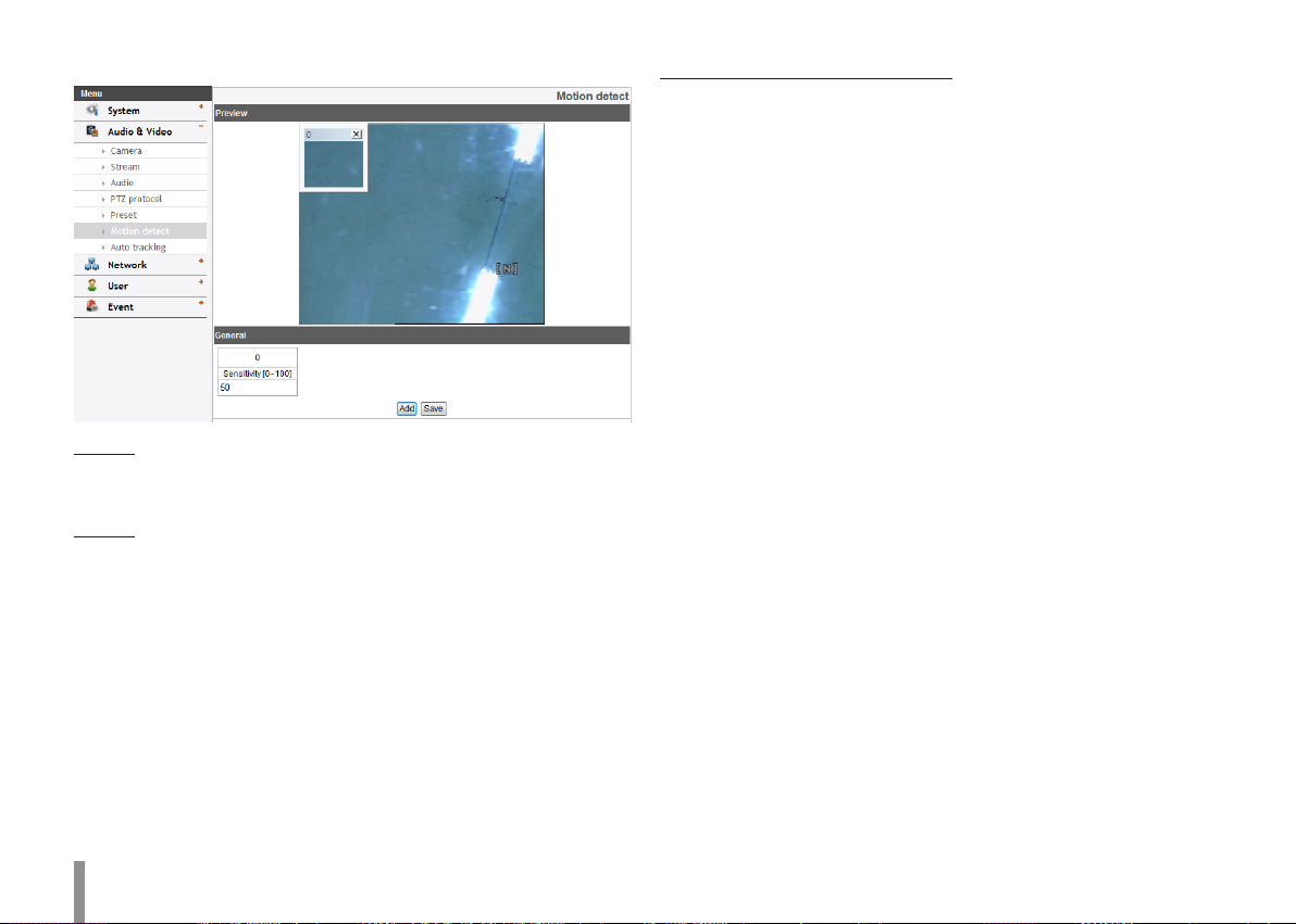
Motion detect
Preview
You can preview the motion detection window on the preview
window.
General
> Sensitivity: Enter the sensitivity to detect an object in motion.
> Save: Click this button to confirm the settings.
How to set the motion detect window
1. Click the [Add] button. The motion detect window is displayed.
You can add the five windows maximum for motion detection
area.
2. Set the [Sensitivity] option.
3. Click the edge or corner of the window box to adjust the
window size for motion detection.
4. Click the [Save] button to save the settings.
Note:
• You can reset the window size. Click one of the window edge or
corner and drag & drop to reset the motion detection area.
• If LSW2010, LDW2010, LVS201 models, Motion Detection can
be activated when at least one of channels (Master/Slave) is
enabled, Video codec is set to H.264 and GOP size is more than
2.
• If not LSW2010, LDW2010, LVS201 models, Motion Detection
can be activated when Master channel is enabled, Video codec
is set to H.264 and GOP size is more than 2.
18 Operation and settings
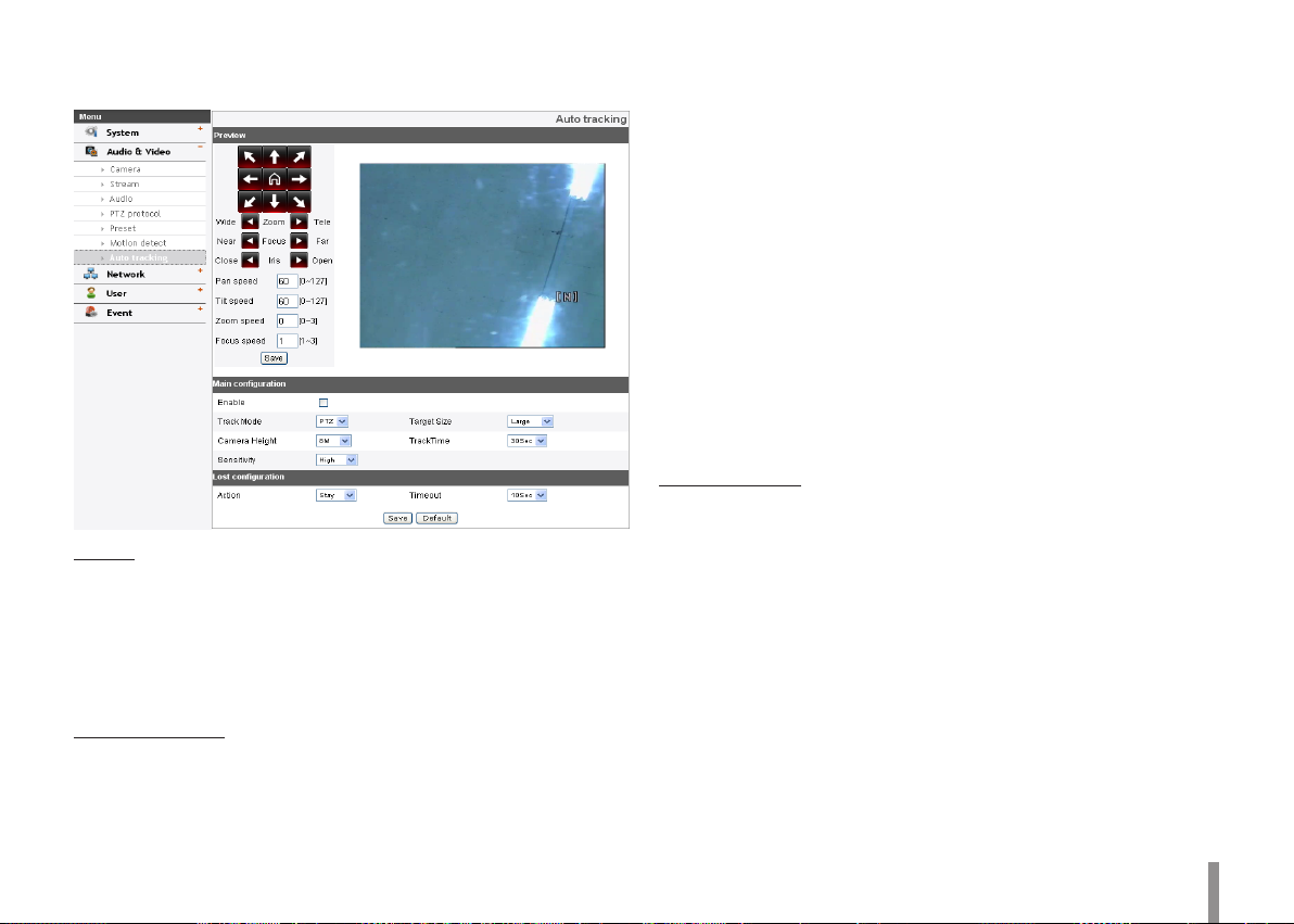
Auto Tracking (LW9228/LW9226/LW9228I/LW9226I/LNP3700T
models only)
Preview
You can see the settings screen from the preview window.
1. Set the camera angle to the point you want with arrow buttons.
2. Adjust the zoom, focus options.
3. Set the Pan, Tilt, Zoom or Focus speed options.
4. Click the [Save] button to confirm the settings.
Main configuration
> Enable: Click the check box if you want to activate this function.
> Track Mode: During perform the Auto Tracking, track the object
using PT(Pan / Tilt) or PTZ(Pan / Tilt / Zoom).
> Target Size
- SMALL: Make images about 1/4 of the object using Zoom
feature.
- MEDIUM: Make images about 1/2 of the object using Zoom
feature.
- LARGE: Make images about 3/4 of the object using Zoom
feature.
> Camera Height: Set to the height of the camera.
> TrackTime: Set the maximum time object tracking.
The camera moved to the initial position after tracking the
amount of time set.
> Sensitivity: Set the sensitivity of detection of objects.
Note:
Low sensitivity setting value can be difficult to detect of small
objects or movement.
Lost configuration
> Action
- Stay: When tracking is failed, the camera stays current
position preparing re-tracking, does not return to the initial
position.
- Return: When tracking is failed, the camera returns to the
initial position preparing re-tracking.
> Timeout: When tracking is failed for the first time, It tries to
re-check the object during set timeout. After that, set action is
performed.
• Save: Click this button to confirm the settings.
• Default: Click this button to restore the IP device back to original
factory settings.
Operation and settings 19
Network settings
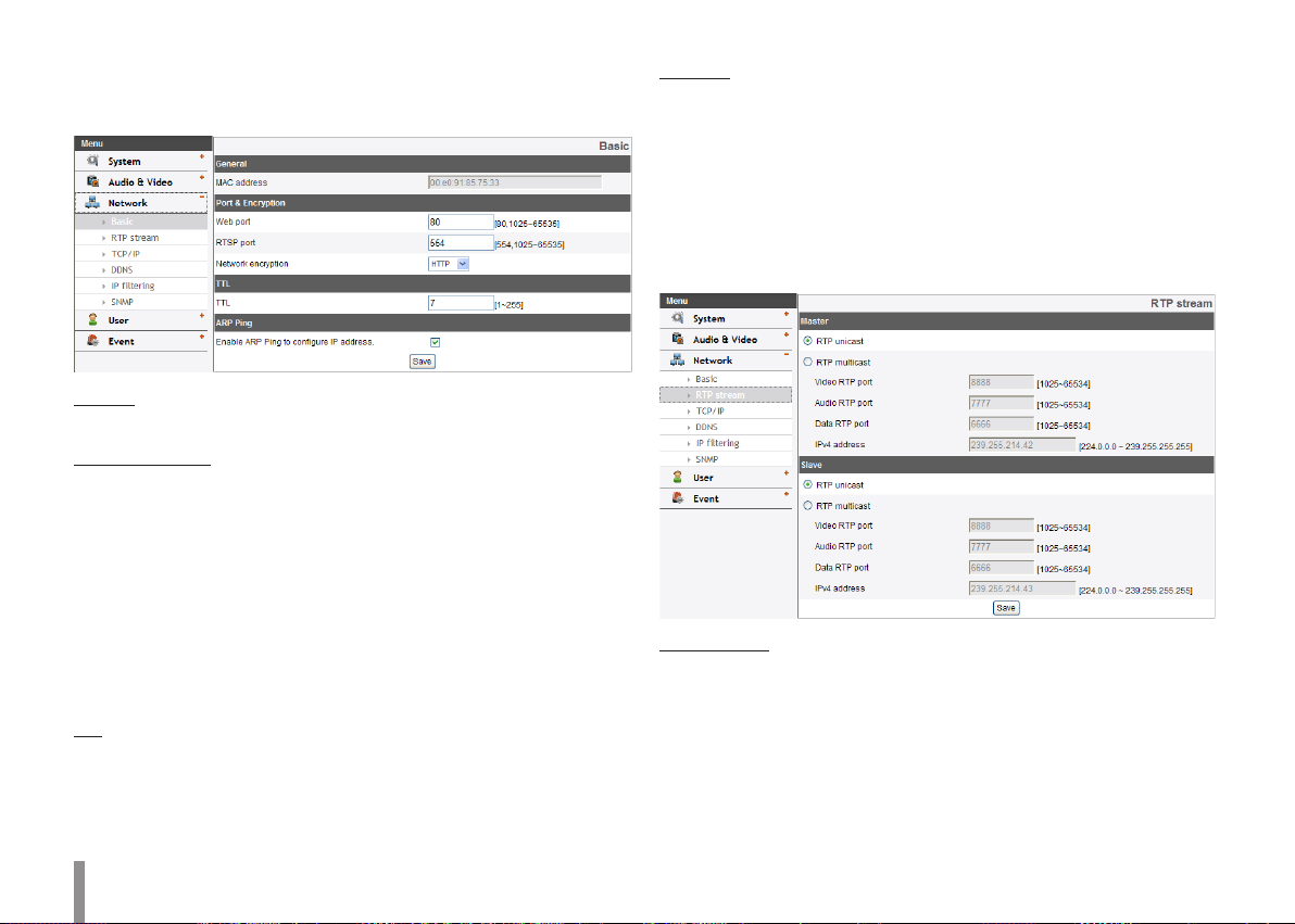
Basic
General
> MAC address: Displays the MAC address.
Port & Encryption
> Web port: The default HTTP port number (80) can be changed to
any port within the range 1 025 to 65 535.
> RTSP port: Check RTSP port. The default port is 554. Other ports
can be selected within the range 1 025 to 65 535.
> Network encryption: Select the HTTP or HTTPS option for
security.
Note:
The RTSP port number should not be same with the web port
number.
TTL
> TTL: This option indicates the Time-To-Live of multicast packets.
The default setting is 7, and the allowed TTL range is from 1 to
255.
ARP Ping
> Enable ARP Ping to configure IP address: Check to enable ARP
ping.
• Save: Click this button to confirm the settings.
RTP stream
RTP (Real-time Transport Protocol) is an internet protocol that allows
programs to manage the real-time transmission of multimedia data, via
unicast or multicast.
Master / Slave
> RTP unicast: When enabled the transmission of the data to the
specified equipment happens on a network specifying a single
address.
20 Operation and settings
> RTP multicast: When enabled it reduces the transmission load
on the camera by making the computer of the same segment
network receive the same transmission data. When multicast
option is checked then select Video Port number, Audio Port
number and Data port number.
- Video RTP port: Specify the video transmission port number
used for the multicast streaming.
- Audio RTP port: Specify the audio port number used for the
multicast streaming.
- Data RTP port: Specify the VA data port number used for
the multicast streaming.
- IPv4 address: Set the IP address for RTP multicast.
Note:
Each stream using multicast needs its own pair of multicast IP
address and port numbers to avoid address conflict.
• Save: Click this button to confirm the settings.
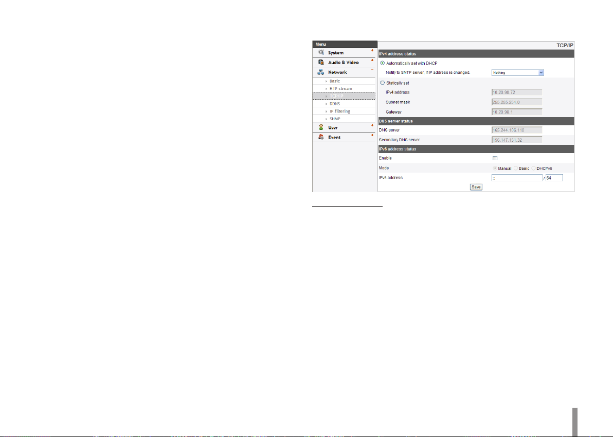
TCP/IP
IPv4 address status
> Automatically set with DHCP: Select this option when a
DHCP server is installed on the network to allow IP address
assignment. With this setting, the IP address is assigned
automatically.
- Notify to SMTP server, if IP address is changed: If you select
this option, the user get a notification mail telling about
changing of IP of the IP device.
Note:
You should register the SMTP server on the Event server setting
to set this function.
> Statically set: Select this option when you set a fixed IP address,
with this setting, specify the IP address, Subnet mask and
default gateway manually.
- IPv4 address: Enter an IP address.
- Subnet mask: Enter a subnet mask address.
Operation and settings 21
 Loading...