

Page 1

OWNER’S MANUAL
Network Dome Camera
Please read this manual carefully before operating
your set and retain it for future reference.
MODELS
LW9228 Series
LW9228I Series
LW9226 Series
LW9226I Series
P/NO : MFL67122201 1104 (V1.5)
Page 2
Safety Information
2
1
1
Safety Information
Safety Information
CAUTION: TO REDUCE THE RISK OF ELECTRIC SHOCK
REFER SERVICING TO QUALIFIED SERVICE PERSONNEL.
CAUTION
RISK OF ELECTRIC SHOCK
DO NOT OPEN
DO NOT REMOVE COVER (OR BACK)
NO USER-SERVICEABLE PARTS INSIDE
This lightning ash with arrowhead symbol
within an equilateral triangle is intended to
alert the user to the presence of uninsulated
dangerous voltage within the product’s
enclosure that may be of sucient magnitude
to constitute a risk of electric shock to persons.
The exclamation point within an equilateral
triangle is intended to alert the user to
the presence of important operating and
maintenance (servicing) instructions in the
literature accompanying the product.
REGULATORY INFORMATION: FCC Part 15
This equipment has been tested and found to comply
with the limits for a Class A digital device, pursuant to Part
15 of the FCC Rules. These limits are designed to provide
reasonable protection against harmful interference when
the equipment is operated in a commercial environment.
This equipment generates, uses, and can radiate radio
frequency energy and, if not installed and used in
accordance with the instruction manual, may cause
harmful interference to radio communications.
Operation of this equipment in a residential area is likely to
cause harmful interference in which case the user will be
required to correct the interference at his own expense.
• A suitable conduit entries, knock-outs or glands shall
be provided in the cable entries of this product in the
end user.
• Caution: Danger of explosion if battery is incorrectly
replaced. Replaced only with the same or equivalent
type recommended by the manufacturer. Dispose
of used batteries according to the manufacturer’s
instructions.
• Holes in metal, through which insulated wires pass,
shall have smooth well rounded surfaces or shall be
provided with brushings.
FCC WARNING: This equipment may generate or use
radio frequency energy. Changes or modications to this
equipment may cause harmful interference unless the
modications are expressly approved in the instruction
manual. The user could lose the authority to operate this
equipment if an unauthorized change or modication is
made.
This Class A digital apparatus complies with Canadian
ICES-003.
Cet appareil numérique de la classe A est conforme à la
norme NMB-003 du Canada.
Page 3
Safety Information
3
Warning: Do not install this equipment in a conned space
such as a bookcase or similar unit.
Warning: Wiring methods shall be in accordance with the
National Electric Code, ANSI/NFPA 70.
Warning: This is a class A product. In a domestic
environment this product may cause radio interference
in which case the user may be required to take adequate
measures.
Warning: To reduce a risk of re or electric shock, do not
expose this product to rain or moisture.
Caution: This installation should be made by a qu alied
service person and should conform to all local codes.
Caution: To avoid electrical shock, do not open the
cabinet. Refer servicing to qualied personnel only.
Caution: The apparatus should not be exposed to water
(dripping or splashing) and no objects lled with liquids,
such as vases, should be placed on the apparatus.
To disconnect power from mains, pull out the mains cord
plug. When installing the product, ensure that the plug is
easily accessible.
LG Electronics hereby declares that this/
these product(s) is/are in compliance
with the essential requirements and other
relevant provisions of Directive 2004/108/
EC, 2006/95/EC, and 2009/125/EC.
European representative :
LG Electronics Service Europe B.V.
Veluwezoom 15, 1327
AE Almere. The Netherlands
(Tel : +31-(0)36-547-8888)
Disposal of your old appliance
1. When this crossed-out wheeled bin
symbol is attached to a product it means
the product is covered by the European
Directive 2002/96/EC.
2. All electrical and electronic products
should be disposed of separately from the
municipal waste stream via designated
collection facilities appointed by the
government or the local authorities.
3. The correct disposal of your old appliance
will help prevent potential negative
consequences for the environment and
human health.
4. For more detailed information about
disposal of your old appliance, please
contact your city oce, waste disposal
service or the shop where you purchased
the product.
EEE Compliance with Directive. (for Turkey only)
1
Safety Information
Page 4

Safety Information
4
IMPORTANT SAFETY INSTRUCTIONS
1
Safety Information
1. Read these instructions.
2. Keep these instructions.
3. Heed all warnings.
4. Follow all instructions.
5. Do not use this apparatus near water.
6. Clean only with dry cloth.
7. Do not block any ventilation openings. Install in
accordance with the manufacturer’s instructions.
8. Do not install near any heat sources such as radiators,
heat registers, stoves, or other apparatus (including
ampliers) that produce heat.
9. Do not defeat the safety purpose of the polarized or
grounding-type plug. A polarized plug has two blades
with one wider than the other. A grounding type plug
has two blades and a third grounding prong. The wide
blade or the third prong are provided for your safety. If
the provided plug does not t into your outlet, consult
an electrician for replacement of the obsolete outlet.
10. Protect the power cord from being walked on or
pinched particularly at plugs, convenience receptacles,
and the point where they exit from the apparatus.
11. Only use attachments/accessories specied by the
manufacturer.
12. Use only with the cart, stand, tripod, bracket, or
table specied by the manufacturer, or sold with the
apparatus. When a cart is used, use caution when
moving the cart/apparatus combination to avoid injury
from tip-over.
13. Unplug this apparatus during lightning storms or when
unused for long periods of time.
14. Refer all servicing to qualied service personnel.
Servicing is required when the apparatus has been
damaged in any way, such as power-supply cord or
plug is damaged, liquid has been spilled or objects
have fallen into the apparatus, the apparatus has been
exposed to rain or moisture, does not operate normally,
or has been dropped.
Safety Precautions
• Do not attempt to disassemble the camera
To prevent electric shock, do not remove screws or
covers. There are no user serviceable parts inside. Ask a
qualied service personnel for servicing.
• Avoid the camera with direct sunlight
Do not aim the camera at bright objects.Whether the
camera is in use or not, never face it with direct sunlight
or other extremely bright objects. Otherwise blooming
or smear may be caused.
• Handle the camera with care
Do not abuse the camera. Avoid striking, shaking, etc.
The camera could be damaged by improper handling
or storage.
• Do not use strong solvents or detergents
Use a dry cloth to the camera when it is dirty. If it is
hard to remove the dirt on the camera, use a mild
detergent and wipe it gently.
• Do not install this camera upside down
This camera is designed for mounting on the ceiling or
wall. If you install this camera upside down, for example,
mounted on the oor, it may cause malfunction.
• Do not use the camera in such places as shown below.
The lens may become cloudy due to condensation if
the camera is used under the following conditions.
› Rapid temperature uctuation by switching an air
conditioner on and o.
› Rapid temperature uctuation due to frequent
door opening and closing.
› Use in an environment where eyeglasses become
foggy.
› Use in a room lled with cigarette smoke or dust.
If the lens becomes cloudy due to condensation,
remove the dome cover and wipe all moist surfaces
with a soft cloth.
Page 5

Safety Information
5
• Before operating, please check proper temperature,
humidity and power source ratings.
Use the camera under conditions where temperature
is from -10 °C to 50 °C and humidity is below 80 %. The
input power source is AC 24 V.
• Consumables
Parts having contacts such as the lens-drive motors,
cooling fan built inside the camera are subject to wear
with time. About replacement and maintenance of
such parts, please ask the nearest service center.
Camera Installation Location
Discuss the installation location for the camera with your
retailer, and select a place that is strong enough
for the installation.
• Install the camera on a ceiling (concrete, etc.) at a
location that is suciently strong to support it.
• Install the camera body on the foundation section
of the building or sections having sucient bearing
strength.
Never install or use the camera in the following
locations
• Do not install it in areas exposed to direct sunlight or
rain.
• Do not install the camera near the air outlet of an air
conditioner.
• Near a swimming pool or other areas where chemicals
are used.
• Food preparation areas and other locations where there
are large amounts of steam vapor and oil, in ammable
atmospheres, other special environments.
• Areas where radiation, X-rays, strong electric waves, or
magnetism is generated.
• At sea, in coastal areas, or in areas where corrosive gas
is being generated.
• Areas outside of the allowable ambient operating
temperature range.
About Static Electricity Removal
Before installing the camera, touch a metal case or other
metallic parts with your hand to remove static electricity
from your body.
Do not install in areas subjected to high amounts of
humidity or dust.
Doing so may cause internal components to damage more
easily or malfunction.
Do not wire cables near power lines.
Tightening the Screws
Screws should be tightened suciently in accordance with
the materials and structure of the installation location. After
tightening the screws, visually inspect them to make sure
there is no unevenness and that each screw is tight.
1
Safety Information
Page 6

Contents
6
Contents
14 ALARM output connections
15 Connecting Network
1
2
1
Safety Information
3
4 IMPORTANT SAFETY INSTRUCTIONS
4 Safety Precautions
4
2
Preparation
5
8 Introduction
8 Features
9 Accessories
6
10 Part Names and Functions
16 Connecting power source
16 Connecting Microphone and Speaker
Device
17 Mounting the camera
17 Removing the Protection Tape
17 Surface mount (optional)
19 Ceiling mount (optional)
21 Wall mount (optional)
23 Pendant mount (optional)
4
Operation and settings
27 Before using the system
27 Recommended PC Requirements
28 Accessing the LG IP device
29 LG Smart Web Viewer Overview
3
Installation
12 Connections
12 Precautions
12 Basic Connection Overview
13 Connecting Display device
13 ALARM input connection
30 Configuring the LG IP camera
30 Accessing the Configuration menu
30 System settings
32 Audio & Video settings
36 Network settings
38 User settings
39 Event settings
42 Auto Tracking
43 OSD Menu Setup
Page 7

Contents
7
46 General operation
46 Camera menu settings
46 Focus setting
47 Exposure settings
48 White Balance setting
48 Day/Night setting
49 3D-DNR setting
49 Color setting
49 Sharpness setting
50 PAN/TILT Settings
50 Privacy Mask setting
50 Special setting
52 OSD Settings
52 User title setting
52 ZOOM MAG setting
52 FUNCTION setting
52 DOME ID setting
6
Appendix
1
58 Specifications
2
3
4
5
53 LANGUAGE Setting
53 RESET Setting
53 Information
53 Initialization
53 Factory reset
5
Reference
54 Troubleshooting
56 Open source software notice
6
Page 8

8
Preparation
2
Preparation
2
Introduction
Preparation
The LG Network Camera is designed to use on an Ethernet
network and must be assigned an IP address to make it
accessible.
This manual contains instructions on how to install and
manage the LG Network Camera in your networking
environment. Some knowledge of networking
environments would be benecial to the reader.
Should you require any technical assistance, please contact
authorized service center.
Features
• High Sensitivity Support
The camera provides the high quality picture with
4.5 mm EX-view HAD CCD.
• Preset Position
Preset position is the function to register camera
monitoring positions (preset positions). Maximum
128 Preset Positions are available. By entering the
position numbers, you can move cameras to the preset
positions. The moving speed and holding time are
adjustable.
• Preset Tour
Preset Tour is the function to go through all the
registered camera monitoring positions (preset
positions). During the working PRESET TOUR, The
FOCUS could not be operated properly under -10 °C
(for LW9226(I) series only)
• Group Tour
Maximum 9 group tours are able to compose the
group of preset, pattern, auto pan that the operator
can program to be linked together in a sequence.
• Pattern recording function
A routine of manual operations can be stored and
reproduced repeatedly. The Pan, Tilt and Zoom controls
are available for pattern recording.
NOTE
The available total time of pattern diers depending
on camera’s operation. When the pattern recording
is full, the pattern recording will automatically stop.
• Privacy Mask
Privacy zone feature enables users to veil unwanted
zones. This setting is used for masking unwanted zones,
hiding them from display on the monitor screen. Up to
8 zones can be registered.
• Auto Pan
The camera has an Auto Pan function that enables to
keep surveillance on every detail occurring around the
specic area, which is preset to watch in advance. The
camera can pan among the maximum 8 points you will
set. The moving speed and holding time are adjustable.
• Auto Flip
When the camera is operated to tilt through the 90°, it
can be watched the opposite side of the locations by
Auto Flip of a 180° horizontally.
• Optical Zoom
- LW9228(I) series: The optical zoom range is 1x to
37x.
- LW9226(I) series: The optical zoom range is 1x to
27x.
• Digital Zoom
Digital zoom enhances the systems zoom range to 12
times beyond the optical zoom limit.
Total system zoom range is below.
- LW9228(I) series: 37x (1x digital zoom) to 444x (12x
digital zoom)
Page 9
Preparation
9
- LW9226(I) series: 27x (1x digital zoom) to 324x (12x
digital zoom)
• Alarm In function (4 channels)
Alarm input signals are supplied from external devices
through the ALARM IN connector.
• Alarm Out function (2 channels)
When an event occurs, the camera sends output
signals via the alarm output connector on the camera.
• Day & Night Function
This camera can be selected Color or Black & White. You
can set Color in the daytime and Black & White at night
due to the low illumination. (Filter Conversion type)
• DSS (Digital Slow Shutter) function
It is possible to highly sensitive surveillance because of
DSS(Digital Slow Shutter) function.
• WDR (Wide Dynamic Range) function
The camera can be best condition to watch easily
inside or outside in the strong back light.
• Power Supply
This camera must always be operated a AC 24 V.
Certied/Listed, class 2 power supply only.
• Auto Tracking
This feature enables the camera to detect a moving
object and track its movement automatically. Based on
the conguration, it is possible to zoom in the object to
identify it clearly.
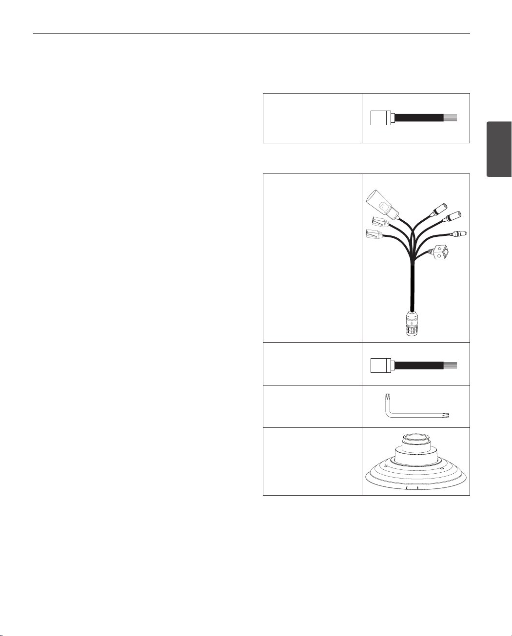
Accessories
For LW9226I/LW9228I series
RJ-45 Adapter cable
For LW9226/LW9228 series
Camera main cable
RJ-45 adapter cable
2
Preparation
Wrench
PIPE Installation Bracket
Page 10
10
Preparation
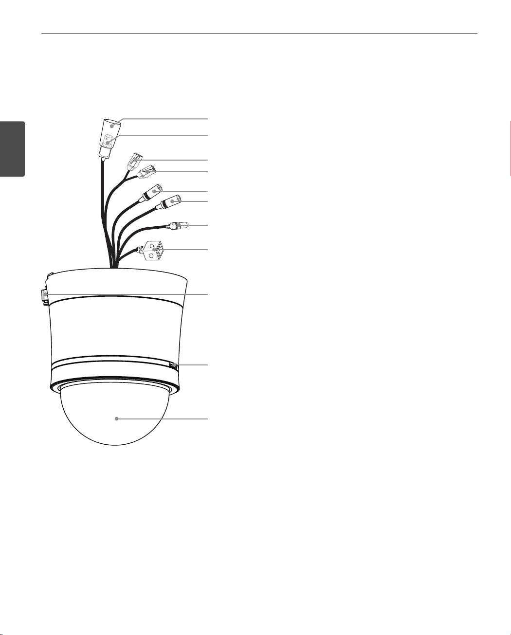
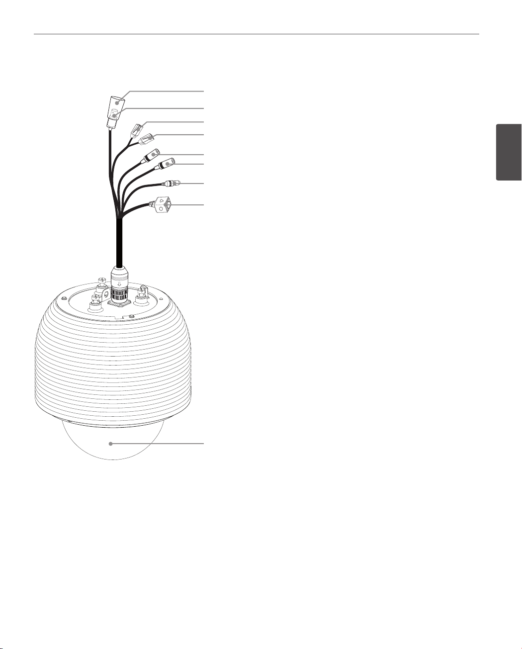
Part Names and Functions
LW9228I/LW9226I series for Indoor
2
Preparation
a
b
c
d
e
f
g
h
i
j
k
a
BNC connector cover cap
b Video output BNC connector
Supplies analog video signal (composite) to the
connected device.
c Data Port A (RJ-45)
Input data port for alarm (relay) signal.
RS-485 data communication is not available.
d Data Port B (RJ-45)
Output data port for alarm (relay) signal.
e
AUDIO IN (Line Level Input)
Input for a mono microphone, or a line-in mono
signal.
f AUDIO OUT (Line Level Output)
Connect to an active speaker with a built-in
amplier.
g
Power input jack
Connects to a AC 24 V power supply using proper
cables.
h ETHERNET Port
Connects to a PC or a network via a hub with a
10 BASE-T/100 BASE-TX cable attached RJ-45
connector.
i
Locking screw
Tighten this screw to xing the Ceiling Mount
Assembly with camera body.
j Dome Cover open button.
k Dome Cover
Page 11
Preparation
11
LW9228/LW9226 series for Outdoor
a
b
c
d
e
f
g
h
a
BNC connector cover cap
b Video output BNC connector
Supplies analog video signal (composite) to the
connected device.
c Data Port A (RJ-45)
Input data port for alarm (relay) signal.
RS-485 data communication is not available.
d Data Port B (RJ-45)
Output data port for alarm (relay) signal.
e
AUDIO IN (Line Level Input)
Input for a mono microphone, or a line-in mono
signal.
f AUDIO OUT (Line Level Output)
Connect to an active speaker with a built-in
amplier.
g
Power input jack
Connects to a AC 24 V power supply using proper
cables.
h ETHERNET Port
Connects to a PC or a network via a hub with a
10 BASE-T/100 BASE-TX cable attached RJ-45
connector.
i
Dome Cover
2
Preparation
i
Page 12
Installation
12
3
Installation
Connections
Precautions
3
• The following steps of installation and connection work should be done by qualied service personnel or system
Installation
installers and should conform to all local codes.
• Before you install and connect the camera, check and prepare the required peripheral devices and cables.
• Before you connect the camera, turn o all devices to be connected, such as this camera and DVR.
• Do not touch the dome cover’s window.
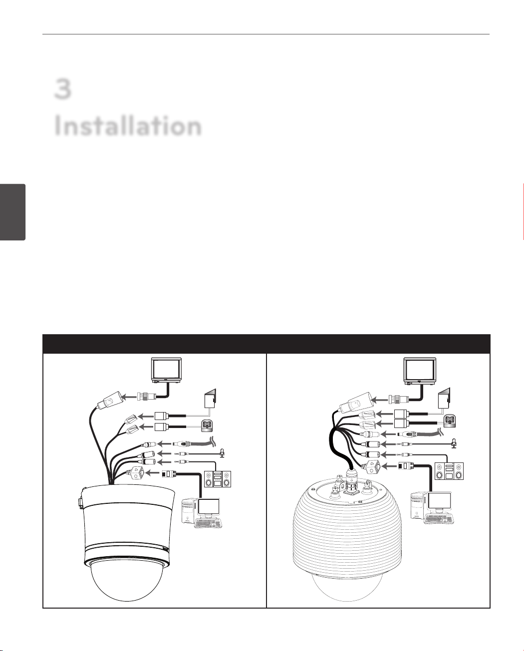
Basic Connection Overview
LW9226I/9228I series (for Indoor) LW9226/9228 series (for outdoor)
Page 13
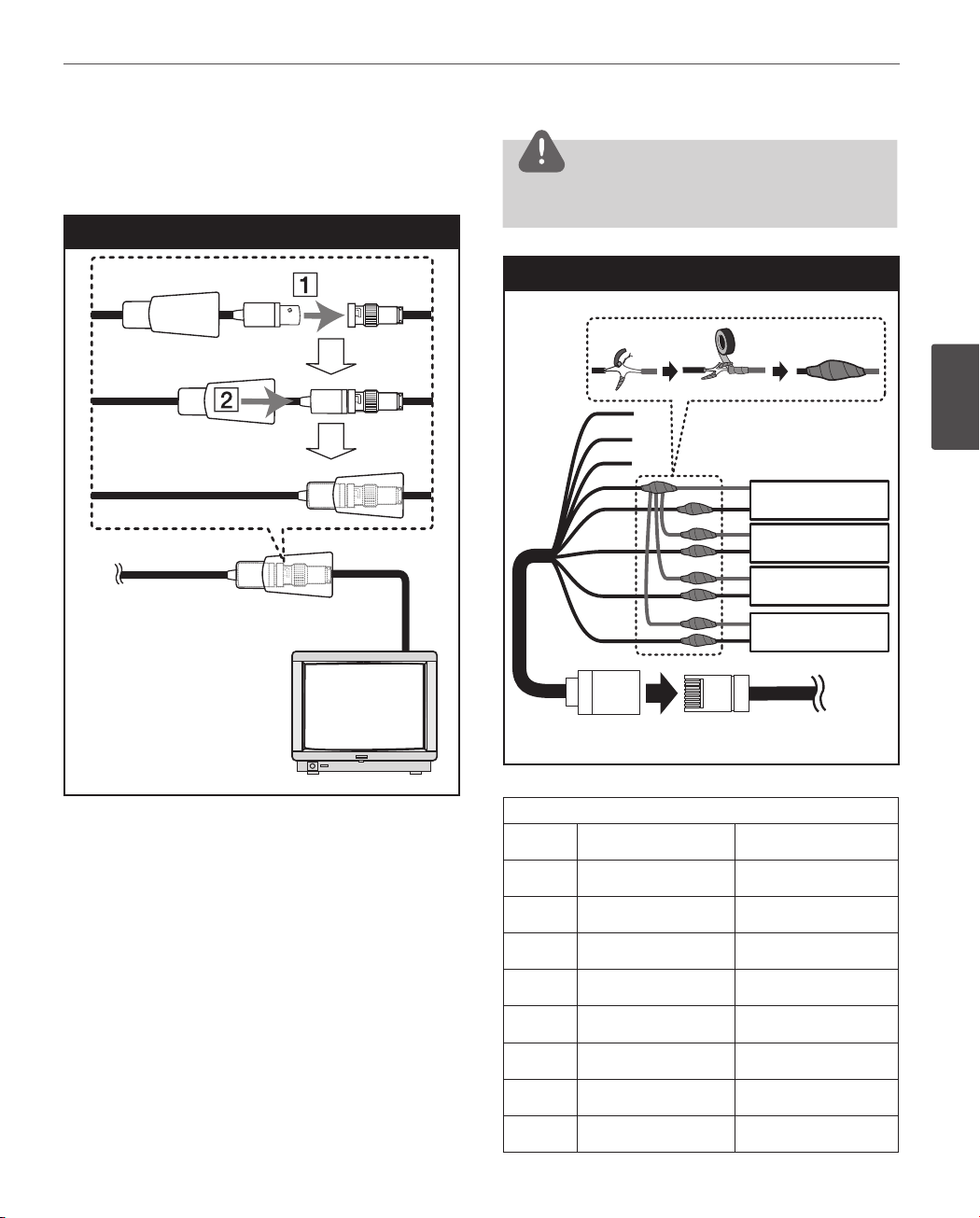
Connecting Display device
The video signal connection between the camera and the
monitor.
Display device connection
Installation
CAUTION
Do not connect one alarm sensor to the several camera’s
alarm input connector.
Alarm input connection
13
ALARM input connection
You can connect up to 4 alarm sensors to the camera. Each
alarm sensor should be connected with Alarm IN COM. You
can adjust the signal state to NO (normally open) or NC
(normally closed) through the setup menu.
1. Connect the RJ-45 Adapter cable to the PORT A (RJ-45)
cable of the camera.
2. Connect the alarm device to the RJ-45 Adapter cable.
When connecting lines, check and connect the color
lines of the each device correctly. Refer to the below
tables for color line information.
A
B
C
D
E
Alarm device
Alarm device
F
Alarm device
G
Alarm device
H
PORT ARJ-45 Adapter cable
RJ-45 Adapter cable
Port A
RJ-45 Adapter cable
No Description Color
A
B
C
D
E
F
G
RS-485 + White
RS-485 - Orange
NC Black
ALARM IN COM Red
ALARM IN 1 Green
ALARM IN 2 Yellow
ALARM IN 3 Blue
3
Installation
Alarm device
Alarm device
Alarm device
Alarm device
H
ALARM IN 4 Brown
Page 14
14
Installation
3
Installation
PORT A of the LW9228I/9226I series
Description Color
RS-485 + Red/White
RS-485 - Black/White
NC
ALARM IN COM Red
ALARM IN 1 White
ALARM IN 2 Light Green
ALARM IN 3 Yellow
ALARM IN 4
PORT A of the LW9228/9226 series
Description Color
RS-485 +
RS-485 - Blue
NC
ALARM IN COM Yellow
ALARM IN 1
Pink
Green
Pink
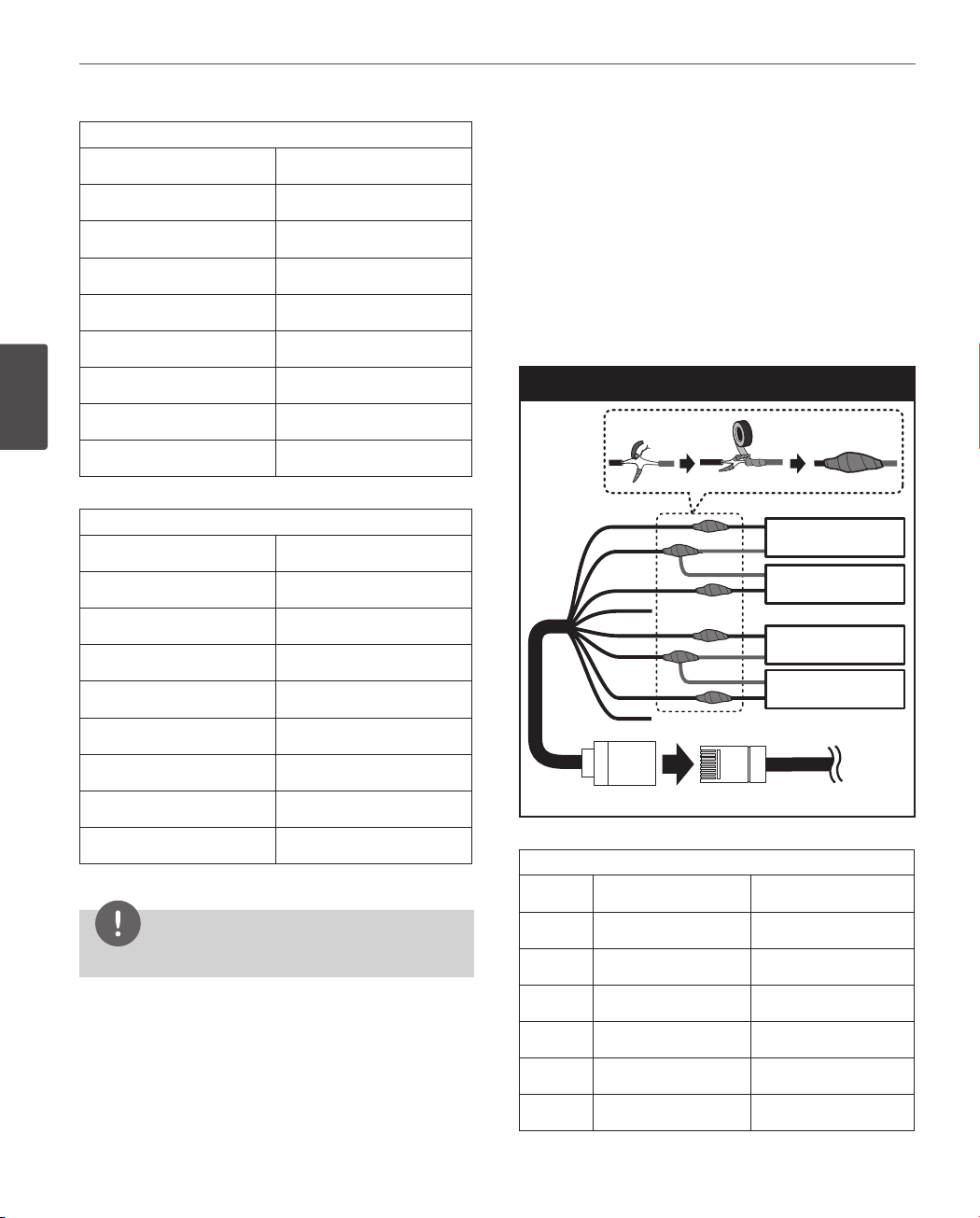
ALARM output connections
Connect the alarm device to the alarm output data port.
Alarm signal output at an event occurrence. You can set the
Alarm Output to the normal open or normal close mode.
1. Connect the RJ-45 Adapter cable to the PORT B (RJ-45)
cable of the camera.
2. Connect the alarm device to the RJ-45 Adapter cable.
When connecting lines, check and connect the color
lines of the each device correctly. Refer to the below
tables for color line information.
Alarm Out connection
A
B
C
D
E
F
G
H
Alarm device
Alarm device
Alarm device
Alarm device
Alarm device
Alarm device
Alarm device
Alarm device
ALARM IN 2 Gray
ALARM IN 3 White
ALARM IN 4 Violet
NOTE
RS-485 data communication is not available.
RJ-45 Adapter cable
PORT BRJ-45 Adapter cable
Port B
RJ-45 Adapter cable
No Description Color
A
B
C
D
E
F
ALARM OUT [NO1] White
ALARM OUT [COM1] Orange
ALARM OUT [NC1] Black
NC Red
ALARM OUT [NO2] Green
ALARM OUT [COM2]
Yellow
Page 15
Installation
15
G
H
PORT B of the LW9228I/9226I series
ALARM OUT [COM1]
ALARM OUT [NO1] Brown
ALARM OUT [COM2] Orange
ALARM OUT [NO2] Black
PORT B of the LW9228/9226 series
ALARM OUT [NC2] Blue
NC Brown
Description Color
ALARM OUT [NC1] Blue
NC
ALARM OUT [NC2] Gray
NC
Description Color
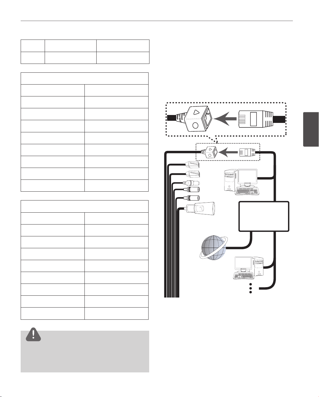
Connecting Network
You can control and monitor the system via network.
With the remote control (monitoring), you can change
the system configuration or monitor the image via network. After the installation, check the network settings
for the remote control and monitoring work.
Connect the IP camera to your network using a standard
RJ-45 network cable as shown below.
Violet
3
Installation
ALARM OUT [NO1] White Blue
ALARM OUT [COM1] Beige
ALARM OUT [NC1] Black
NC
ALARM OUT [NO2] Brown
ALARM OUT [COM2] Red
ALARM OUT [NC2]
NC
Orange
CAUTION
Output specications are lowactive, open-collector and
a drive capacity of 30 V DC 0.5 A maximum.
Connecting the alarm out incorrectly may cause
damaging the camera.
Page 16
16
Installation
Connecting power source
Connect a AC 24 V power source to the power input
terminal as shown below.
3
Installation
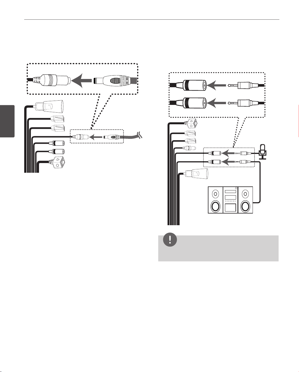
Connecting Microphone and Speaker Device
Optionally connect an active speaker and/or external
microphone with a built-in amplifier.
NOTE
Keep the microphone away from the speaker to avoid
howling.
Page 17
Installation
17
Mounting the camera
You can mount the camera on the ceiling or wall.
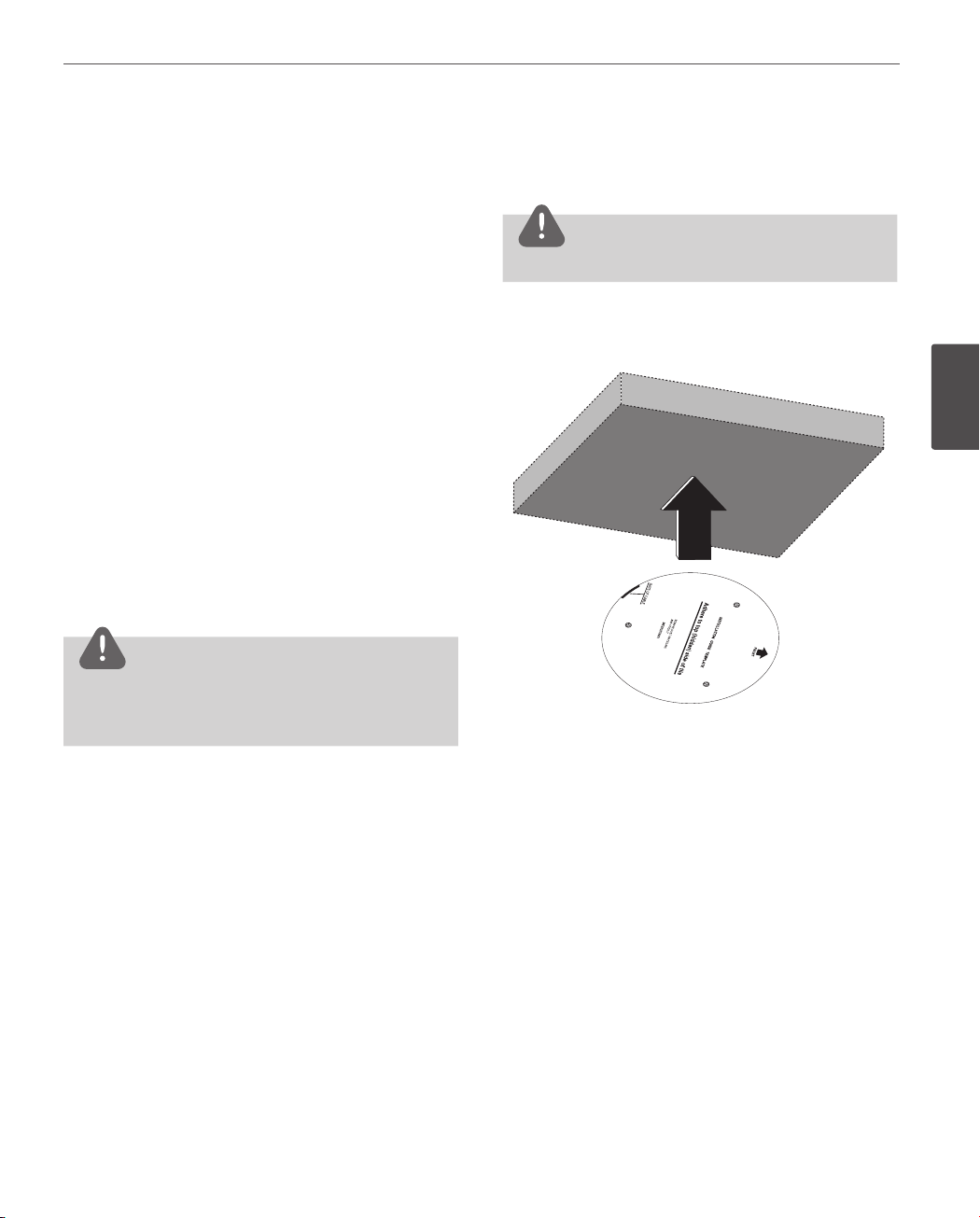
Removing the Protection Tape
You should remove the protection tape before installing
the camera.
Remove the protection tape carefully.
For LW9226/9228 series models.
1. Loosen the screws using the wrench and remove the
dome cover.
2. Remove the protection tape and attach the dome
cover.
For LW9226I/9228I series models.
1. Press the Dome Cover open button and then
disassemble the dome cover by using ALIGN mark.
2. Remove the protection tape and attach the dome
cover.
CAUTION
Surface mount (optional)
Follow the instructions below to surface mount the
camera.
CAUTION
The building structure must be able to support 8 kg.
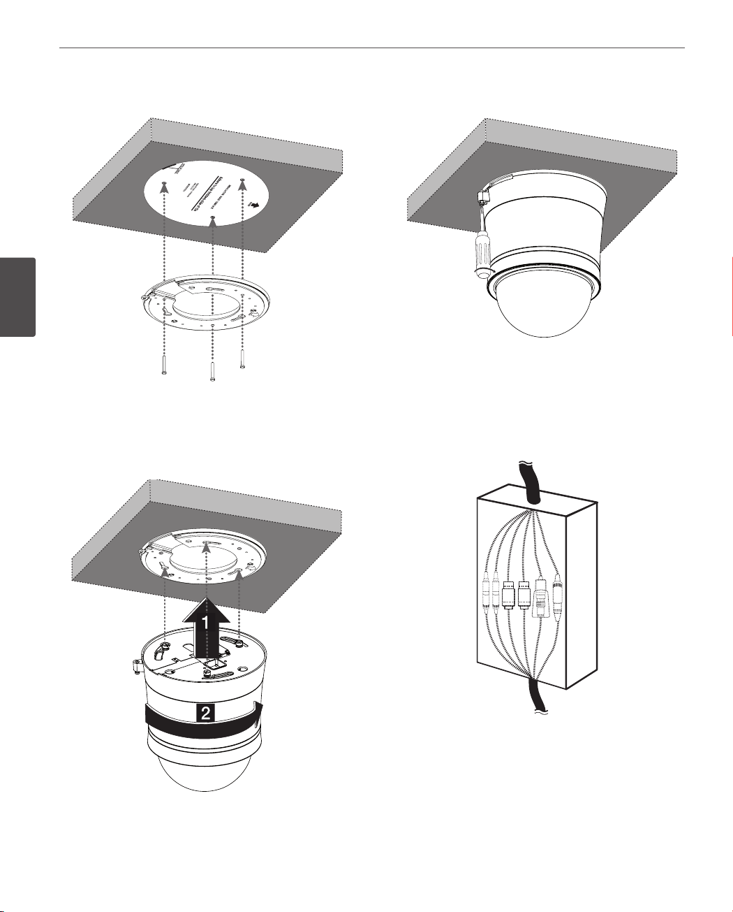
1. Use the installation guide template to check the
mounting location. Face the front of the label toward
the area of interest.
3
Installation
You must align the OPEN and LOCK mark correctly when
you turn the dome cover to open or close.
If you do not align the mark, it causes a malfunction.
Page 18
18
Installation
2. Install the surface mounting bracket on the ceiling.
3
Installation
3. Assemble the camera and the surface mounting
bracket by following step a and b. Align the locking
point of the surface mounting bracket and the camera.
4. Tighten the locking screw.
5. Connect the cables to the cable jacks of the camera
body. After installing the camera, you should arrange
the cables using the outlet box to protect the cables.
Page 19

Installation
19
Ceiling mount (optional)
Follow the instructions below to mount the camera on the
ceiling.
CAUTION
The building structure must be able to support 8 kg.
1. Make a hole through the ceiling as shown below.
Ø 166 mm
2. Fasten the safety cable to the building superstructure.
The building superstructure can vary depending on
your installation environment.
3. Install the ceiling mounting bracket on the ceiling. Face
the front of the ceiling mounting bracket toward the
area of interest.
3
Installation
4. Tighten the screws until the ceiling mounting bracket
holds the ceiling rmly.
Page 20

20
Installation
5. Pass the connection cable through the inner side of
the ceiling. Connect the cables to the cable jacks of the
camera body.
3
Installation
7. Tighten the locking screw.
8. Connect the cables to the cable jacks of the camera
body. After installing the camera, you should arrange
the cables using the outlet box to protect the cables.
6. Assemble the camera and ceiling mounting bracket by
following step a and b. Align the locking point of
the surface mounting bracket and the camera.
CAUTION
Do not expose the connected part of the camera cable
jacks in the rain or moisture.
Page 21

Installation
21
Wall mount (optional)
Install the camera by the following order.
1. Disassemble the PIPE Installation Bracket to remove the
[A] part.
[A]
2. Install the PIPE Installation Bracket to the Wall Mount
assembly.
3. Connect the safety cable to the wall mount assembly.
Red Stripe
3
Installation
Page 22

22
Installation
4. Drill a hole on the wall where you want to install the
pipe. Pass the connection cable through the wall
mount assembly so that they hang down.
3
5. Install the wall mount assembly.
Installation
7. Attach the camera to the camera assembly bracket by
following step a and b. Align the locking point of
the wall mount assembly and the camera.
8. Tighten the locking screw.
6. Connect the connection cable and the safety cable to
the camera body.
Page 23

Installation
23
9. Assemble the camera cover as shown below.
Pendant mount (optional)
Install the camera by the following order.
1. Disassemble the PIPE Installation Bracket to remove the
[A] part.
[A]
2. Install the PIPE Installation Bracket to the Pendant
Mount assembly.
3
Installation
NOTE
You can install the PIPE Installation Bracket direct to the
other type LG Wall Mount assembly. This LG Wall Mount
assembly make to easy to install your camera.
Page 24

24
Installation
3. Connect the safety cable to the pendant mount
assembly.
Red Stripe
3
Installation
4. Drill a hole on the wall where you want to install the
pipe. Pass the connection cable through the pendant
mount assembly so that they hang down.
Page 25

Installation
25
5. Install the pendant mount assembly.
6. Connect the connection cable and the safety cable to
the camera body.
7. Attach the camera to the camera assembly bracket by
following step a and b. Align the locking point of
the wall mount assembly and the camera.
3
Installation
8. Tighten the locking screw.
Page 26

Installation
26
9. Assemble the camera cover as shown below.
3
Installation
NOTE
You can install the PIPE Installation Bracket direct to the
other type LG Wall Mount assembly. This LG Wall Mount
assembly make to easy to install your camera.
Page 27

4
Operation and settings
Operation and settings
27
Before using the system
• Before using the LG IP device make sure the
connections are correct and verify whether proper
power supply is used.
• Check the connections of the LG IP device for the
correct conditions.
• Check that the LG IP device is(are) connected to the
network and that power is supplied.
• Once the connections are made you need to install the
LG client program to the PC from which you want to
access the device.
The LG Smart Web Viewer program is automatically
installed when you connect the LG IP device.
The LG Smart Station and the LG Smart Web Viewer
program are the network program of the LG Video
Server and the LG IP cameras.
• To view streaming video in Internet Explorer, set your
browser to allow ActiveX controls. If you nd this
message “This website wants to install the following
add-on: ‘IPCam_Streamer.cab’ from ‘LG ELECTRONICS
INC’ ”, Click the yellow bar and install LG Smart Web
Viewer Program on your computer.
• The Layouts and the Live view pages may dier with
dierent OS (Operating Systems) and Web Browsers.
• Care needs to be taken not to run any other
applications when the Client Program is running as it
may cause memory shortage.
Recommended PC Requirements
The LG IP device can be used with most standard operating
systems and browsers.
Items Requirements
Operating System Windows XP Professional
CPU
Web Browser
DirectX DirectX 9.0 or above
Memory 2 GB or above RAM
Graphics Card 256 MB or above Video RAM
Resolution
Intel Core2 Quard Q6700 (2.66
GHz) or above
Microsoft Internet Explorer 6.0 or
higher
1280 x1024 (with 32 bit color) or
higher
4
Operation and settings
Page 28

Operation and settings
28
Accessing the LG IP device
You can access the LG IP device by following the below
steps.
1. Copy the IP Utility to your PC
1.1 Insert the Client Program CD.
1.2 Find and Copy IP Utility folder to your PC.
2. Discover the LG IP device using the
IP Utility
The IP Utility can automatically discover and display LG IP devices on your network.
The IP Utility shows the MAC address, IP address,
Model name and so on.
4
Operation and settings
3. Logging in to the LG Smart Web
NOTE
The computer running the IP Utility must be on
the same network segment (physical subnet) as
the LG IP device.
2.1 Run the IP Utility program.
2.2 Click the [Search] button or select the
[Search] option in the Device search menu.
After a few seconds the found LG IP devices gets displayed in the IP Utility window.
Viewer
The LG Smart Web Viewer can be used with most
web browsers. The recommended browser is
Internet Explorer with Windows.
3.1 Run the IP Utility and find the LG IP devic-
es.
3.2 When the LG IP devices appear in the IP
Utility window, double-click IP address
or right click on the same IP address and
select “Connect to Web Page” to start the
LG Smart Web Viewer. When accessing the
LG Smart Web Viewer, the authentication
dialog appears on the screen.
3.3 Enter the user name and password. (Note
that the default administrator user name
and password are “admin”.)
3.4 Click the [OK] button and then the LG
Smart Web Viewer is displayed in your
browser.
Notes:
• You can also access the LG Smart Web Viewer
as shown below.
3.1 Start your Web browser.
3.2 Enter the IP address of the LG IP device in
the address bar of the browse.
3.3 Enter the user name and password set by
the administrator.
3.4 Click the [OK] button and then the LG
Smart Web Viewer is displayed in your
browser.
• The LG Smart Web Viewer needs more time to
display it according to the network conditions.
• If the login window is not displayed, check the
pop-up blocker. If you set the pop-up blocker,
the login window is not displayed. You must
allow the pop-ups.
• If you connect the LG Smart Web Viewer for
the first time, the Security Warning window is
displayed to install the LG Smart Web Viewer
program. You must install the LG Smart Web
Viewer program for using the LG IP device.
• If your computer or network is protected by a
proxy or firewall, the proxy or firewall settings
can prevent the LG Smart Web Viewer program. Change the proxy or firewall settings to
activate the LG Smart Web Viewer program.
Page 29

Operation and settings
29
LG Smart Web Viewer Overview
Item Description
Select the video image size
from the drop-down list. (AUTO,
D1 or CIF)
The initial view size is set to
AUTO. The AUTO option sets
the view size according to the
Server’s resolution.
Displays the current video
codec of the selected video
stream (Master or Slave).
Check this option as the
network connection type (TCP
or UDP). If you check it, the
client connects to the server
using TCP connection.
Click to save the current
image in JPEG format on your
computer.
1. Click the [Snapshot] button
and then the Snapshot
window is displayed.
2. Click the [Save] button in
the Snapshot window.
3. Enter the le name (JPEG
format) and select the folder
to save it.
4. Click the [Save] button to
conrm it.
5. Click the [Close] button in
the Snapshot window to
close it.
Displays the Camera OSD
control window. Use these
buttons to setup the Camera.
This button does not appear on
the screen if the login is other
than the administrator.
Displays the PTZ control
window. Use these buttons to
control the PTZ unit.
This button is not displayed
with normal or anonymous user.
Select the video stream. From
the Live view drop-down list,
select the desired video image
source between [Master-0] and
[Slave-0].
NOTE
Master and Slave are output
video streams. You can set
the stream congurations
independently for either
Master or Slave stream. This
would facilitate the user
to set the live view at his
comfort.
4
Operation and settings
Page 30

Operation and settings
30
4
Operation and settings
Provides all the necessary tools
for setting up the device to your
requirements. The user will need
administrator level to do this.
Note:
If you want to exit the
Conguration menu, select one
of the video stream in the Live
view drop-down list.
Displays the current surveillance
live screen.
You can monitor the camera
image on the live view window
of the LG Smart Web Viewer.
Click this button to connect
or disconnect the audio
communication between the
LG IP device and the connected
PC.
(Color icon: On, Gray scale icon:
O.)
Click this button to switch the
microphone o and on for the
computer.
(Color icon: On, Gray scale icon:
O.)
Click this button to switch
the sound o and on, for the
speaker of the computer.
(Color icon: On, Gray scale icon:
O.)
Configuring the LG IP
camera
The features and options of the LG IP camera are configured through the Configuration menu.
Only administrator-level users have permission to access
the Configuration menu.
Accessing the Configuration menu
Click the [Conguration] button to display the LG Smart
Web Viewer conguration window.
Warning
The Conguration setup should be made by qualied
service personnel or system installers.
System settings
Version
Displays the current version of Firmware, Hardware,
Software and Web Client.
Page 31

Operation and settings
31
Date & Time
Time zone
Set the time dierence from GMT in the area where the IP
device is installed.
Select the time zone in the area where the IP device is
installed from the drop down list.
Time mode
› Synchronize with NTP Server: Select if you want
to synchronize the IP device’s date and time with
those of the time server called NTP (Network Time
Protocol). Specify the NTP server’s name. Click the
[Test] button for connection test to the server.
› Synchronize with personal computer: Select if you
want to synchronize the IP device’s date and time
with your computer.
› Synchronize manually: Select if you want to set the
IP device’s date and time manually. Select the year,
month and date by clicking the calendar button.
Set hour, minutes and seconds in the edit boxes.
Server time
› Server time: Displays the current date and time of
the IP device.
• Save: Click this button to conrm the settings.
Maintenance
System reboot
Click the [Reboot] button to restart the IP device. It takes
some minutes for the IP device to start again.
Restore and backup
› Backup: To take a backup all of the settings. If
necessary, it make possible to return to a backuped
conguration. Click this button and follow the
instructions on the browser to specify the folder
and save the setting data of the IP device. This
conguration backup can be restored whenever
needed.
› Restore:
1. Click the [Browse] button.
2. Find and open the file in which the configuration setting data is stored.
3. Click the [Upload] button.
4. Click the [Restore] button after successfully
uploading the backup configuration. The system settings will be restored and reboot the
system.
NOTE
4
Operation and settings
• Backup and Restore can happen on IP
device having the same version of rmware.
This feature is not intended for multicongurations or for rmware upgrades.
• [Backup] function is allowed in HTTP protocol
but not in HTTPS protocol.
Page 32

Operation and settings
32
4
Operation and settings
Firmware
› Upgrade
1. Click the [Browse] button.
2. Find and open the firmware file.
3. Click the [Upload] button.
4. Click the [Upgrade] button to update the firmware.
NOTE
When you upgrade the system, it may take some
minutes to be done. Do not close the browser
while the upgrade is in progress. If you close the
browser, it may cause a malfunction.
› Initialize: The [Initialize] button should be used with
caution. Clicking it will return all of the IP device’s
settings to the factory default values. (Except for
the Network settings - DHCP, IP address, Gateway,
Subnet mask, Primary/Secondary DNS)
Log & Report
Language list
Select a language for the LG Smart Web Viewer
conguration menu and information display.
• Save: Click this button to conrm the settings.
Audio & Video settings
Camera
Preview
You can preview the camera image on the preview
window.
Log & Report status
The System log provides a summary of the status of the IP
device. The unit records the data of the software activity in
a le.
› View Log: Click this button to display the system
log information.
› View report: Click this button to display the report
of the system.
Language
General
› Contrast: Edit the contrast value from 0 to 100.
Selecting 100 provides the image with the highest
contrast.
› Brightness: Edit the brightness of the camera. It
is brighter when a large value is selected and it is
darker when a small value is selected.
› Standard: Displays the video standard of the
camera.
› Hue: Edit the video Hue of the camera from 0 to
100.
• Save: Click this button to conrm the settings.
• Default: If you want to set the Contrast, Brightness and
Hue options to the default value, click the [Default]
button and then click the [Save] button to conrm it.
Page 33

Operation and settings
33
Stream
Master/Slave
› Enable: Click to activate the stream function.
› Deinterlacing: Click to enable the use of
deinterlacing function.
› Video codec: Select the video mode (Codec)
from the drop-down list. The viewer can choose
between MJPEG and H.264.
› Resolution: Select the image size to be sent from
the camera.
NTSC D1 (704 x 480), HALF D1 (704 x 240),
CIF (352 x 240) and QCIF (176 x 112)
PAL D1 (704 x 576), HALF D1 (704 x 288),
CIF (352 x 288) and QCIF (176 x 144)
› Maximum frame rate: Set the frame rate of the
image. Selectable values of the frame rates are as
follows.
NTSC 1 to 30 (fps)
PAL 1 to 25 (fps)
› Bit rate: If the [Quality] option set to CBR, this
option is displayed. Edit the bit rate value from 256
kbps to 10 240 kbps.
• Save: Click this button to conrm the settings.
Audio
Audio In
› Enable: Click the check box if you want to send the
audio from the microphone input connector.
NOTE
The Clients connected to the IP device remain
unaected with additional changes made in the
setting.
› Audio type: Select the codec when you send the
audio from the microphone input connector.
Audio Out
› Enable: Click the check box to output the audio
from the speaker.
• Save: Click this button to conrm the settings.
4
Operation and settings
› GOP size: It means “Group of Pictures”. The higher
the GOP, the better is the video quality of the
camera. Edit the value of GOP from 1 to 30. This
setting is valid for H.264 video format only.
› Quality: Select the Quality.
- VBR: The bit rate may vary depending on the
complexity of the video to meet the selected
quality.
- CBR: The video quality may vary in order to
preserve a constant bit rate.
› Stream quality: If the [Quality] option set to VBR,
this option is displayed. Select the stream quality
from the drop down box, the camera supports ve
types (Highest, High, Medium, Low and Lowest)
PTZ protocol
Page 34

Operation and settings
34
PTZ configuration
› Enable: Click to use the PTZ protocol.
› Pan speed: Enter the panning speed of the PTZ
device in the edit box. Default value for the LG
Multix Protocol is 60 and ranges from 0 to 127.
› Tilt speed: Enter the tilting speed of the PTZ device
in the edit box. Default value for the LG Multix
Protocol is 60 and ranges from 0 to 127.
› Zoom speed: Enter the zoom speed of the PTZ
device to view the object close or at a distance.
Default value for the LG Multix protocol is 0 and
ranges from 0 to 3.
› Focus speed: Enter the focus speed of the PTZ
device to focus an object clearly near or far. Default
value for the LG Multix protocol is 1 and ranges
from 1 to 3.
› Preset tour park time: Enter the parking time.
• Save: Click this button to conrm the settings.
4
Preset
Operation and settings
NOTE
While conguring PATTERN/PRESET/GROUP TOUR/AUTO
PAN, turn o Auto Tracking feature temporarily.
Preview
You can see the settings screen from the preview window.
1. Move the camera to the point you want by using the
arrow buttons.
2. Adjust the zoom, focus or iris options.
3. Set the Pan, Tilt, Zoom or Focus speed options.
4. Click the [Save] button to conrm the settings.
Pattern
You can activate the camera in a repeating pattern. The
pattern is programmed by recording your manual pan, tilt,
and zoom operations. The camera stores the movements
you performed in memory.
» To record the pattern
1. Click the [Start recording] button to start the pattern
recording.
2. Move the camera through the desired movement.
3. Click the [Stop recording] button to stop the pattern
recording.
NOTE
The available total time of pattern diers depending on
connected PTZ device and operation.
» To play the pattern
1. Click the [Play] button to play the programmed pattern.
2. Click the [Stop] button to stop playing.
Preset
Preset position is the function to register camera
monitoring positions (preset positions) associated with
position numbers. By entering the position numbers, you
can move cameras to the preset positions.
» To register preset position
1. Enter the preset number you wish to register.
2. Move the camera to a point you wish.
3. Click the [Add] button.
4. Repeat the steps 1 to 3 to add other positions.
» To remove the preset position
1. Enter the memorized preset index number.
2. Click the [Remove] button. The preset will be
deleted.
» Changing a picture in a preset position
1. Enter the memorized preset index number.
2. Click the [Go to preset] button. The camera moves
to the preset position and the picture of the
camera in that position appears on the monitor.
Page 35

Operation and settings
35
Preset tour
A preset tour is composed of a group of preset positions
that the operator can link together in a sequence.
1. Click the [Play] button to start the preset tour.
2. Click the [Stop] button to stop the preset tour.
NOTE
If you control the PTZ, the preset tour will be stopped.
Preset group tour
You can create a group using preset positions that are
registered already. A maximum of 9 groups is available.
» To set the group
1. Enter the group number in the [Group index]
option.
2. Enter the preset index number in the [Preset index]
option.
3. Click the [Add] button.
4. Repeat the steps 2 to 3 to add other preset index
number. You can set the preset index number up
to 8 for the one group.
5. Repeat the steps 1 to 4 to set the other group
index.
» To remove the preset index from the group
1. Enter the group number in the [Group index]
option.
2. Enter the preset index number in the [Preset index]
option.
3. Click the [Remove] button.
4. Repeat the steps 2 to 3 to remove other preset
index number.
5. Repeat the stpes 1 to 4 to set the other group
index.
» To tour the group
1. Enter the group number in the [Group index]
option.
2. Click the [Play] button to start the group tour.
3. Click the [Stop] button to stop the group tour.
» To delete a group
1. Enter the group number in the [Group index]
option.
2. Click the [Clear] button. The group will be deleted.
Auto pan
You can play the camera with auto pan function.
» To set the Auto Pan position
1. Enter the index number you wish to register.
2. Move the camera to the desired point.
3. Click the [Add] button.
4. Repeat the steps 1 to 3 to add other index number. You can set the Auto pan index number up to
8.
» To play the auto pan
1. Click the [Play] button to start the Auto Pan
function.
2. Click the [Stop] button to stop the Auto Pan
function.
NOTE
If you click the [CLEAR] button, all of Auto pan position
will be deleted.
Motion detect
Preview
You can preview the motion detection window on the
preview window.
General
› Sensitivity: Enter the sensitivity to detect an object
in motion.
› Save: Click this button to conrm the settings.
4
Operation and settings
Page 36

Operation and settings
36
» How to set the motion detect window
1. Click the [Add] button. The motion detect window
is displayed. You can add the five windows maximum for motion detection area.
2. Set the [Sensitivity] option.
3. Click the edge or coner of the window box to
adjust the window size for motion detection.
4. Click the [Save] button to save the settings.
4
Network settings
Operation and settings
NOTE
• You can reset the window size. Click one of
the window edge or corner and drag & drop
to reset the motion detection area.
• Motion Detection can be activated when the
Master channel is enabled and Video codec
is set to H.264.
NOTE
The RTSP port number should not be same with
the web port number.
TTL
› TTL: This option indicates the Time-To-Live of
multicast packets. The default setting is 7, and the
allowed TTL range is from 1 to 255.
ARP Ping
› Enable ARP Ping to congure IP address: Check to
enable ARP ping.
• Save: Click this button to conrm the settings.
RTP stream
RTP (Real-time Transport Protocol) is an internet protocol
that allows programs to manage the real-time transmission
of multimedia data, via unicast or multicast.
Basic
General
› MAC address: Displays the MAC address.
Port & Encryption
› Web port: The default HTTP port number (80) can
be changed to any port within the range 1 025 to
65 535.
› RTSP port: Check RTSP port. The default port is 554.
Other ports can be selected within the range
1 025 to 65 535.
› Network encryption: Select the HTTP or HTTPS
option for security.
Master / Slave
› RTP unicast: When enabled the transmission of
the data to the specied equipment happens on a
network specifying a single address.
› RTP multicast: When enabled it reduces the
transmission load on the camera by making the
computer of the same segment network receive
the same transmission data. When multicast option
is checked then select Video Port number, Audio
Port number and Data port number.
- Video RTP port: Specify the video transmission
port number used for the multicast streaming.
It is initially set to 8 888 and you can edit this
between 1 025 and 65 534.
Page 37

Operation and settings
37
- Audio RTP port: Specify the audio port number
used for the multicast streaming. It is initially
set to 7 777 and you can edit this between
1 025 and 65 534.
- Data RTP port: Specify the VA data port number
used for the multicast streaming. It is initially
set to 6 666 and you can edit this between
1 025 and 65 534.
- IP address: Set the IP address for RTP multicast.
NOTE
Each stream using multicast needs its own a
pair of multicast IP address and port numbers to
avoid address conict.
• Save: Click this button to conrm the settings.
TCP/IP
IP address status
› Automatically set with DHCP: Select this option
when a DHCP server is installed on the network to
allow IP address assignment. With this setting, the
IP address is assigned automatically.
- Notify to SMTP server, if IP address is changed:
If you select this option, the user get a
notication mail telling about changing of IP of
the IP device.
NOTE
You should register the SMTP server on the Event
server setting to set this function.
- Subnet mask: Enter a subnet mask address.
- Gateway: Enter the gateway address.
DNS server status
› Primary DNS server: Enter the Primary domain
name server that translates the hostnames into IP
address.
› Secondary DNS server: Enter the Secondary DNS
server address that backups the Primary DNS.
• Save: Click this button to conrm the settings.
DDNS
This free service is very useful when combined with the LG
DDNS Server. It allows the user to connect the IP device
using the URL, rather than an IP Address. This also solves
the problem of having a dynamic IP address.
4
Operation and settings
DDNS status
› Don’t use DDNS server: Disable the DDNS function.
› Use DDNS server: Enable the DDNS function.
- Provider: Displays the DDNS provider.
- Hostname: Enter the hostname you want to
use.
• Save: Click this button to conrm the settings.
IP filtering
The access of the IP addresses in the list are allowed or
denied according to the choice made in the drop-down list
of the Basic policy option. The administrator can add up to
10 IP address entries to the list (a single entry can contain
multiple IP addresses). The users from these IP addresses
need to be specied in the user list with the appropriate
access rights. The IP list is to control the access permission
of clients by checking the client IP address.
› Statically set: Select this option when you set a xed
IP address, with this setting, specify the IP address,
Subnet mask and default gateway manually.
- IP address: Enter an IP address.
Page 38

Operation and settings
38
IP list
› Basic policy: Select the basic policy type.
- Allow all: Allow all the IP address basically, but
the IP addresses in the list are denied.
- Deny all: Deny all the IP address basically, but
the IP addresses in the list are allowed. It needs
at least one IP address to activate this function.
• Save: Click this button to conrm the settings.
4
Operation and settings
• Add: Click this button to add the IP address.
1. Click the [Add] button.
2. Set the IP options.
- Alias: Enter the alias.
- From: Enter the start IP address for the IP
ltering.
- To: Enter the end IP address for the IP ltering.
NOTE
If you want to deny or to allow a range of IP
addresses, enter the start IP address to “From”
and the end IP address to “To”. You can also add
an IP address by entering the same IP address to
“From” and “To”.
3. Click the [Save] button.
4. Repeat the steps 1 to 3 to add additional IP
address.
• Remove: Click this button to delete the IP address.
1. Select the alias from the list.
2. Click the [Remove] button. The IP address will be
deleted.
User settings
Basic
The IP device is shipped with the login rights of
administrator only. If others need to access the IP device
excluding the conguration a login with viewer rights need
to be created. A maximum of 50 users can be created.
User list
› Add the User
You can register a new user with various access
rights.
1. Click the [Add] button. User setting dialog is
displayed.
2. Enter the new User ID and Password. (Should
have a minimum of 4 characters and preferably
a combination of alphanumeric).
3. To confirm the password, retype the password
that you typed in the Password box.
4. Select the authority from the drop down list
to provide the access rights to each user and
then click the [Save] to confirm your selection.
- Administrator: Allows you to operate setup
menus and to view live images.
- Power user: Use of the limited functions
of the system (The Conguration menu is
not allowed). A power user can use the Live
View, OSD control and audio functions.
- Normal user: Provides the lowest level of
access, Allows to view live images only.
Page 39

Operation and settings
39
- Custom user: The user can login and
view the live stream image only when
the “Enable anonymous login” option is
checked to enable it.
NOTE
Remember the password.
› Edit the registered user
You can change the password or authority.
1. Choose the user ID and then click the [Edit]
button.
2. Change the Password or Authority, then click
the [Save] button to confirm your selection.
› Delete the registered user
1. Choose the user ID you want to delete.
2. Click the [Remove] button.
NOTE
The default administrator user ID ‘admin’ is
permanent and cannot be deleted.
Anonymous
› Enable anonymous login
Check the box to enable anonymous user login
- allows the user access for only viewing the live
stream image.
Video Codec Resolution
H.264 D1 30 HIGHEST Up to 5
H.264 D1 30 MEDIUM Up to 10
MJPEG D1 30 MEDIUM Up to 1
MJPEG Half D1 30 MEDIUM Up to 2
MJPEG D1 15 MEDIUM Up to 10
Frame
Rate
Quality
Maximum
RTP
stream
NOTE
Preview window of the IP device setting and
preset setting are aected by this setting.
• Save: Click this button to conrm the settings.
Event settings
Event schedule
When an event (Modtion detect/ Sensor Event) occurs, this
unit records the live images and routes as congured.
4
Operation and settings
Maximum RTP stream connection
› Maximum number of simultaneous stream
connection:
Set this number to limit the number of simultaneous stream connections.
The connections depend on the stream configuration as shown in the following Maximum RTP
stream connection by stream configuration.
Page 40

Operation and settings
40
4
Operation and settings
Event schedule list
» To edit the Event Schedule
1. Select the Trigger event and click the [Edit] button.
Event schedule window is displayed.
2. Set the options.
• Trigger: Displays the selected trigger event.
• Time: Sets the weekday, Start, Finish, Pre alarm,
Post alarm and Ignore interval time options.
• Action: Selects the options. This occurs when
the event runs.
- FTP server/SMTP server: Uploading
of images to an FTP server, or e-mail
notication.
- Control relay: The relay is activated or
deactivated.
• Stream: Selects the stream of the connected
camera.
• Default: Sets to default setting value.
3. Click the [Save] button to confirm the settings.
NOTE
You should register the SMTP and FTP server on the
Event server setting to set this function.
Event Server
Event Servers are used to receive the recorded video clip
and/or notication messages.
FTP server list
Image les can be transferred to the FTP server within the
scheduled time. Image le that has been recorded linked
to an external event is sent to the FTP server periodically.
» To add the FTP server
1. Click the [Add] button. FTP server setting window
is displayed.
2. Set the FTP server options.
- Alias: Type the FTP Server name to upload the
image les.
- Address: Enter the FTP server’s IP address.
- Port: Enter the port number. The default FTP
port is 21.
- User ID: Type the user name for the Folder
shared in the FTP server.
- Password: Type the password for the folder
shared in the FTP Server.
- Folder: Type the path with the folder that is
shared in the FTP server.
- Test: Select [Test] to test the FTP server.
3. Click the [Save] button to confirm the settings.
» To edit the FTP server
1. Choose the FTP server in the FTP server list.
2. Click the [Edit] button.
You can check or edit the FTP server options.
» To delete the FTP server
1. Choose the FTP server in the FTP server list.
2. Click the [Remove] button. This would remove the
FTP server from the list.
Page 41

Operation and settings
41
SMTP server list
By selecting the e-mail option, a still image of the event is
captured and an e-mail with the attached image le is sent
to the specied mail address.
» To add the SMTP server
1. Click the [Add] button. SMTP server setting window is displayed.
2. Set the SMTP server options.
- Alias: Enter the SMTP server name.
- User ID: Enter the user ID of the SMTP server.
This would be the one who owns the mail
account.
- Password: Enter the password of the SMTP
server.
- Address: Enter the SMTP server address.
- Port: Enter the port number. The default port is
25.
- Enable SSL: Check when use the SSL (Secure
Socket Layer) protocol. SSL protocol is
cryptographic protocols that provide secure
communication on a network.
- Receiving address: Type the recipients e-mail
address. You can specify only one recipient
e-mail address.
- Administrator address: Type the e-mail address
of the administrator.
- Subject: Enter the subject/title of the e-mail.
- Message: This message can describe the
information of the acquired IP address, etc.
- Test: Select [Test] to test the SMTP server.
3. Click the [Save] button to confirm the settings.
» To edit the SMTP server
1. Choose the SMTP server in the SMTP server list.
2. Click the [Edit] button.
You can check or edit the SMTP server options.
» To delete the SMTP server
1. Choose the SMTP server in the SMTP server list.
2. Click the [Remove] button.
Sensor & Relay
Sensor
› Enable: Marks up when you want to activate the
sensor.
› Alias: Displays the sensor name.
› Type: Select the sensor type.
Relay
› Control duration: Enter the relay time.
› Alias: Displays the relay name.
› Type: Select the relay type.
› Control relay
- Run: Click to activate the relay.
- Stop: Click to stop the relay.
• Save: Click this button to conrm the settings.
4
Operation and settings
Page 42

Operation and settings
42
Auto Tracking
Normal Scenario for Auto Tracking
Object detecting state
The camera starts to search a moving object. It may not
starts the detecting under the some conditions. See ‘About
Auto Tracking’.
Object tracking state
If the camera detects the object, it starts to track the object.
When it uses PTZ in tracking, it’ll zoom in the object if
it is small. If some OSD such as USER TITLE, ZOOM MAG,
FUNCTION, DOME ID, and COMPASS are enabled, they are
hidden from this state.
Recovery state
When the camera is congured to PTZ mode and lost the
4
object, it will zoom out to re-tracking the object.
Operation and settings
Lost state
If the camera fails to re-tracking the object, it can stay its
position or return to the initial position where the tracking
was started. The hidden OSD is shown from this state.
• The Auto Tracking is disabled temporary while the
camera is moving based on some congurations:
PRESET TOUR, GROUP TOUR, PATTERN TOUR, and AUTO
PAN.
• When NIGHT MODE or the camera height value is
congured to 2.5M, ZOOM function will be inactivated
to operate Auto Tracking correctly.
• The following conditions can cause operational errors
or make Auto Tracking impossible.
- An object that is not distinguishable from
background at low luminance.
- An object that has similar color with
background.
- A lot of moving objects
- Unsteady camera
- Environments where a shadow is long
- Environments where there is extreme ickering
or where there is light shining and light
reection on the dome
While PRESET TOUR / GROUP TOUR / AUTO
PAN
• When the camera is stopped at one preset position, it
follows the normal scenario for the preset dwell time.
• If a moving object is detected, the camera tracks the
object until the lost state.
• If a moving object is not detected for the dwell time,
it goes to the next preset position. While it is moving
to the next position, the Auto Tracking is stopped
temporary.
• Because of the OSD, Auto Tracking might operate
incorrectly while PRESET TOUR/GROUP TOUR/AUTO
PAN.
About Auto Tracking
• The Auto Tracking is stopped when a user moves the
camera (Pan/Tilt/Zoom) or turns on OSD Menu. It is
started again whenever a user stops the control.
Page 43

Operation and settings
OSD Menu Setup
The following table shows the list of menu items and options. You can adapt the camera to your requirements by setting up
the respective items in these menus.
1st level 2nd level 3rd level Contents
43
CAMERA SET
FOCUS
EXPOSURE
WHITE BALANCE
DAY/NIGHT
FOCUS MODE
FOCUS DIST
RETURN
IRIS AUTO/MANUAL
AGC OFF/LOW/MIDDLE/HIGH
WDR/BLC OFF/WDR/BLC/HSBLC
BRIGHTNESS 0 to 100
SHUTTER OFF, A.FLK, 1/160, …, X2, AUTO
SENS-UP
RETURN
ATW
AUTO
MANUAL
ONE PUSH
AUTO
DAY
NIGHT
AUTO/MANUAL/ONE PUSH/
ZOOM TRIG
LW9228 series: 50 CM, 1.8 M, 3 M, 6 M
LW9226 series: 50 CM, 1 M, 3 M, 5 M
AUTO X2/AUTO X3/…/AUTO X128/
OFF
COLOR TEMP INDOOR/OUTDOOR
RED - 100 to +100
BLUE - 100 to +100
RETURN
D/N LEVEL LOW/MIDDLE/HIGH
DWELL TIME 5,10,15,30,60 SEC
RETURN
4
Operation and settings
Page 44

Operation and settings
44
PAN/TILT SET
4
Operation and settings
OSD SET
OFF
3D-DNR
COLOR
SHARPNESS 0 to 68
RETURN
PRIVACY MASK
SPECIAL
RETURN
USER TITLE ON/OFF
ZOOM MAG ON/OFF
FUNCTION ON/OFF
DOME ID ON/OFF
RETURN
LOW
MIDDLE
HIGH
ON COLOR -20 to 20
OFF
MASK NUMBER 1 to 8
SET MASK
MASK STATE ON/OFF
MASK COLOR GRAY, WHITE, BLACK
WIDTH 2 to 320
HEIGHT 3 to 240
RETURN
PROPORTIONAL PT ON/OFF
COMPASS SET/ON/OFF
HOME POSITION
AUTO RETURN
TILT LIMIT ON/OFF
RETURN
ON
OFF
ON
OFF
SET
GO
DWELL TIME(0 to 100)
RETURN
RETURN TIME
(1 MIN to 100 MIN)
Page 45

Operation and settings
45
LANGUAGE
RESET
RETURN
The option depends
on the model.
INFORMATION
INITIALIZATION
FACTORY RESET
RETURN
4
Operation and settings
Page 46

Operation and settings
46
General operation
1. Click the [OSD control] button on the LG Smart Web
Viewer.
2. Click button.
The camera setting menu appears on the live view
window.
4
Operation and settings
3. Use or button to select an option then click
button. Submenu appears.
4. Use or button to select a submenu option.
5. Use or button to select a value.
6. Click button to exit the setup menu.
In the submenu, use or button to select the
[RETURN] option and click button to return to the
previous.
NOTE
• button: Used to move upper direction on the
menu screen.
button: Used to move lower direction on the
•
menu screen.
button: Used to increase the value selected in the
•
menu.
button: Used to decrease the value selected in the
•
menu.
button: Executes selections and displays a
•
submenu for an item with the mark.
Camera menu settings
Focus setting
The camera adjusts the focus automatically by sensing the
center of the picture.
.
Focus mode
Select [FOCUS MODE] option on the [FOCUS] menu, then
select the following mode.
• AUTO: Auto-focus is activated automatically.
• MANUAL: Focus is activated automatically after the
zoom movement is nished. If you want to control the
focus manually, press the FOCUS ( or ) buttons on
the controller.
• ONE PUSH: The focus is activated manually. If the
camera is received auto-focus command, the camera
is activated auto-focus mode and the focus is set
automatically and then the focus mode is automatically
changed to manual mode.
• ZOOM TRIG: The focus is activated manually. If you
change the zoom, the focus is activated automatically
and then the focus mode is automatically changed to
manual mode.
Page 47

Operation and settings
47
Focus Distance setting
Selects the minimum shooting distance for the focus.
Select [FOCUS DIST] option on the [FOCUS] menu, then
select a focus distance value.
Exposure settings
.
Iris setting
Select the desired lens iris value for camera exposure.
Select [IRIS] option on the [EXPOSURE] menu, then select a
value.
• AUTO: The lens iris is set automatically.
• MANUAL: Use or button to select the DC Iris level.
DC Iris level are set by one parameter unit.
WDR/BLC setting
Use WDR/BLC option to set the options for BLC or WDR
camera.
1. Select [WDR/BLC] option on the [EXPOSURE] menu.
2. Use or button to select a mode then press .
• WDR LEVEL: WDR (Wide dynamic range) feature
can be very helpful to cope with very challenging
lighting conditions. It is capable of capturing both
of the dark part and bright part and combining
the dierences into a scene to generate a highly
realistic image as original scene. Set the WDR level
(LOW, MIDDLE, HIGH).
• BLC LEVEL: Camera’s backlight compensation
feature helps alleviate issues of visibility in high
contrast areas. Set the BLC level (LOW, MIDDLE,
HIGH).
• HSBLC: Use for masking brightness of the specic
area to view the subject more clearly.
- HSBLC LEVEL: Select the HSBLC level. (LOW,
MIDDLE, HIGH).
- COLOR: Use or button to select a color.
• OFF: Not used.
BRIGHTNESS setting
You can increase the brightness of the darkened video.
If you set the brightness to lower value, the image gets
darkened. If you set the brightness to higher value, the
image gets bright.
1. Select [BRIGHTNESS] option on the [EXPOSURE] menu.
2. Use or button to set the bright level.
4
Operation and settings
AGC (Automatic Gain Control) setting
If the images are too dark, change the maximum
[AGC] value to make the images bright.
1. Select the [AGC] option on the [EXPOSURE] menu.
2. Use or button to select a mode.
Page 48

Operation and settings
48
SHUTTER (Shutter Speed) setting
Select the desired shutter speed for camera exposure. You
can change the shutter speed to higher speed to capture
fast-moving subjects, though the image becomes darker.
1. Select [SHUTTER] option on the [EXPOSURE] menu.
2. Use or button to set shutter speed.
SENS-UP setting
If pictures are not clear due to darkness, use this function
to increase the sensitivity of picture.
1. Select [SENS-UP] option on the [EXPOSURE] menu.
2. Use or button to set the SENS-UP limit. To set the
SENS-UP function, select the [AUTO] on the [SHUTTER].
NOTE
If you set to one of the SHUTTER options except AUTO
on the [SHUTTER] menu, the [SENS-UP] setting is not
available and [---] mark is displayed.
4
Operation and settings
White Balance setting
Select the method by which the camera shifts its output
colors to compensate for the color of a light source.
- When the scene mostly contains high color
temperature objects, such as a blue sky or
sunset.
- When the scene is dim.
• AUTO: In this mode, the color temperature range
for the proper white balance is approximately
2 700 K to 5 400 K. Proper white balance may not
be obtained under the following conditions:
- When the color temperature is out of the
2 700 K to 5 400 K range.
- When the scene mostly contains high color
temperature objects, such as a blue sky or
sunset.
- When the scene is dim.
• ONE PUSH: If you select the ONE PUSH mode,
you will be able to set up the White Balance
automatically using button.
• MANUAL: You can set the white balance options
manually.
- COLOR TEMP: Use or button to select a
function.
› INDOOR: The color temperature range for
the proper white balance is approximately
3 200 K.
› OUTDOOR: The color temperature range for
the proper white balance is approximately
5 100 K.
- RED: Set the desired red value.
- BLUE: Set the desired blue value.
1. Select the [WHITE BALANCE] option on the [CAMERA
SET] menu.
2. Use or button to select a mode then press .
• ATW (Auto-Tracing White Balance): In this mode,
the color temperature range for the proper white
balance is approximately from 1 800 to 10 500 K.
Proper white balance may not be obtained under
the following conditions:
- When the color temperature is out of the
1 800 K to 10 500 K range.
Day/Night setting
1. Select [DAY/NIGHT] option on the [CAMERA SET ]
menu.
2. Use or button to select the mode.
• AUTO: DAY/NIGHT mode changes automatically.
Page 49

Operation and settings
49
- D/N LEVEL: Use or button to select a level.
- DWELL TIME: Use or button to select a
dwell time.
NOTE
If you set the AGC to [OFF] or the SHUTTER is set to one
of the SHUTTER options except AUTO on the [EXPOSURE]
menu, the AUTO mode of the DAY/NIGHT function is not
available and [---] mark is displayed.
• DAY: Color mode enabled.
• NIGHT: Black-and-white mode enabled.
3D-DNR setting
Color setting
You can switch the displayed picture to grayscale or color.
1. Select the [COLOR] option on the [CAMERA SET] menu.
2. Use or button to change a color eect.
• ON: To display the picture with color. Select ON and
press to display the submenu. You can adjust
the color level using the or button.
• OFF: To display the picture with grayscale.
Sharpness setting
Sharpens the image outline.
4
Operation and settings
1. Select the [3D-DNR] option. If pictures are not clear due
to brightness, use this function to reduce the noise of
picture.
2. Use or button to select an option.
NOTE
• If you set the AGC to [OFF] on the [EXPOSURE] menu,
the [3D-DNR] function is not available.
• When you use this function, the afterimage may
occur.
1. Select the [SHARPNESS] option on the [CAMERA SET]
menu.
2. Use or button to adjust the option. If you set the
sharpness value to higher, the image outline becomes
sharp. If you set to lower value, the image outline
becomes dim.
Page 50

Operation and settings
50
PAN/TILT Settings
Privacy Mask setting
This function is aiming at the protection of personal
privacy, the mask zone is not displayed on the screen. Up
to 8 zones can be registered.
4
Operation and settings
.
7. Use or button to select the color of the mask
zone box on the [MASK COLOR] option.
8. Select the [WIDTH] option and use or button to
adjust the horizontal size of the mask zone box.
9. Select the [HEIGHT] option and use or button to
adjust the vertical size of the mask zone box.
10. Repeat steps 3 to 9 to add additional positions.
NOTE
• The parts with the registered mask numbers from
1 to 4 have the same color. (So do the parts with
the numbers from 5 to 8). If you change the mask
color, the registered mask color will be changed
automatically with the same color for each of group
(1 to 4, 5 to 8).
• The initial PRIVACY MASK color is set to black . After
setting, the PRIVACY MASK position on [SET MASK]
option, it`ll be changed to gray color.
Be sure, you have to press button on the [SET
MASK] option to conrm the privacy mask color.
Special setting
1. Select the [PRIVACY MASK] option on the [PAN/TILT
MENU].
2. Press button to display the PRIVACY MASK MENU.
3. Use or button to select a zone number on the
[MASK NUMBER] option.
4. Select the [SET MASK] option and press button.
5. Select the mask zone using the PTZ control buttons
and then press button to save it.
6. Use or button to set to [ON] or [OFF] on the
[MASK STATE] option. If you already registered the mask
zone and set to ON, the mask zone box appears on the
monitor.
Proportional PT
This function optimizes the image by automatically
adjusting the PAN/TILT (horizontal/vertical rotation) speed
according to the zoom ratio.
1. Select [PROPORTIONAL PT] option on the [SPECIAL]
menu.
2. Use or button to toggle it on and o.
• ON : Pan/tilt speed is in inverse proportion to the
zoom ratio.
• OFF : The speed is constant at the fastest level
regardless of the zoom ratio.
Page 51

Operation and settings
51
Compass
You can display the north, south, east and west information
on the screen.
1. Select [COMPASS] option on the [SPECIAL] menu.
2. Set the [COMPASS] option to [SET] and then press
button.
3. Select north point using the PTZ control buttons and
then press button.
4. Set the [COMPASS] option to [ON].
Home position
The home position is the camera’s basic position.
The camera returns to this position whenever you want.
Use the following procedure to make the home position.
1. Select [HOME POSITION] option on the [SPECIAL]
menu.
2. Use or button to set it ON.
3. Press button.
4. Select [SET] option and then press button.
5. Select the home position where you want and then
press button.
6. Select [DWELL TIME] option and then select the dwell
time.
7. Select [RETURN] option and press button to exit the
setting menu.
» Go to Home position
1. Select [HOME POSITION] option on the [SPECIAL]
menu.
2. Use or button to set it ON.
3. Press button.
4. Select [GO] option and then press button. The
camera will move to the home position.
Auto return
This function can be used to specify automatic return to a
particular mode if a certain amount of time elapses without
any operation being performed.
1. Select [AUTO RETURN] option on the [SPECIAL] menu.
2. Use or button to set it [ON] and then press
button.
3. Select [RETURN TIME] option and then select the auto
return time.
4. Select [RETURN] option and press button to exit the
setting menu.
NOTE
If you set [AUTO RETURN] to [ON], the [HOME POSITION]
option is set to [OFF] automatically and you can not use
it.
Tilt limit
You can specify the tilt range. If you set this function, the
camera is able to tilt from 15º to 165º.
1. Select [TILT LIMIT] option on the [SPECIAL] menu.
2. Use or button to set it [ON]. If you do not want to
use this function, set it to [OFF].
4
Operation and settings
NOTE
• If you do not want to use the home position
function, set the [HOME POSITION] option to [OFF].
• If you set the [HOME POSITION] to [ON], the [AUTO
RETURN] option is set to [OFF] automatically and you
can not use it.
Page 52

Operation and settings
52
OSD Settings
.
4
Operation and settings
User title setting
You can use the camera identication to assign a number
and character to the camera.
1. Select [USER TITLE] option on the [OSD] menu.
2. Use or button to set it [ON].
3. Press button. The USER TITLE menu appears.
4. Use , , or button to select a character,
number, symbol mark or option item.
• CLR: If you enter the wrong code, select [CLR] then
press . All letters will be erased at once.
• POS: Move the USER TITLE position on the screen
using the or buttons.
• END: Select this option to exit the settings.
ZOOM MAG setting
Displays or removes the zoom OSD on the screen.
1. Select [ZOOM MAG] option on the [OSD] menu.
2. Use or button to set it [ON] or [OFF].
3. Select [RETURN] option and press button to exit the
setting menu.
FUNCTION setting
Displays or removes the Function OSD on the screen.
1. Select [FUNCTION] option on the [OSD] menu.
2. Use or button to set it [ON] or [OFF].
3. Select [RETURN] option and press button to exit the
setting menu.
DOME ID setting
Displays or removes the Camera ID OSD on the screen.
1. Select [DOME ID] option on the [OSD] menu.
2. Use or button to set it [ON] or [OFF]
3. Select [RETURN] option and press button to exit the
setting menu.
NOTE
USER TITLE, ZOOM MAG, FUNCTION, DOME ID, and
COMPASS are hidden when the camera starts tracking
an object. When the tracking is stopped, those will be
displayed as congured.
A
• </>: Moves cursor to left or right.
(Blank): Insert a space at the cursor position.
• A
Page 53

Operation and settings
53
LANGUAGE Setting
Select a language for the setup menu and OSD display.
RESET Setting
Information
You can view the current camera information such as PTZ
software version, camera software version, camera ID,
Protocol and Baud Rate.
1. Select [INFORMATION] option on the [RESET] menu.
2. Press button to display the current camera
information.
Initialization
You can initialize the camera settings.
1. Select [INITIALIZATION] option on the [RESET] menu.
2. Press button then conrmation window is displayed.
3. Select [YES] and press button.
Factory reset
Clear certain settings and information and return to factory
default settings.
1. Select [FACTORY RESET] option on the [RESET] menu.
2. Press button then conrmation window is displayed.
3. Select [YES] and press button. The camera will return
to the factory default settings.
4
Operation and settings
.
Page 54

54
Reference
5
Reference
Troubleshooting
This section provides useful information to help you to
resolve any diculty you might have with your LG IP
device. Fault symptoms, possible causes and remedial
actions are provided here.
IP Setting problems
• ARP/Ping: Disconnect and reconnect the power to the
network camera. The device should get the IP within 2
minutes.
• Ping your camera: Open the command prompt on your
computer, type ping with the IP address of the network
5
Reference
device. The reply obtained by this command provides
explanation for the cause of the problem.
1. bytes = 32 time = 2 ms indicates that the IP
address is already used and cannot reuse the
same. A new IP address needs to be obtained.
2. Destination host unreachable: indicates that the
network device and your computer do not fall
in the same subnet hence needs to get a new IP
address. Contact the system administrator for the
required help.
3. Request timed out: Indicates that the IP is free as it
is not used by anyone and the network device can
obtain this.
• IP Conicts: If the LG network device is set with a static
IP address and if the DHCP option is set then there may
be IP’s same as the network device and other network
partner. Hence set the static IP address to 0.0.0.0 to
resolve this conict.
Cannot access the camera from browser:
• Reconnect the network camera with power and check
the ping operation to know if the IP is used by others.
• Disable the proxy setting in the Browser if you are using
a proxy server.
• Check for proper cabling and network connections, try
to ping after verifying the connectivity.
• Sometimes when HTTPS is enabled, we would be
checking the URL with http, in this case manually
change the URL to the http/https accordingly.
• Verify the DNS and Gateway settings if the IP address is
assigned statically to the network device.
Accessing camera external to the local network
• Firewall Protection: Check for the internet rewall with
the system administrator, either he has to do port
forwarding or modify the DMZ function on the router.
• Default router needed: Check if you need congure the
router settings.
Sporadic network performance
• Network Switches or hubs used may be of the lower
conguration and the load on this may not meet the
required conditions of our network camera.
• Check for the RJ-45 cables that are used for the network
connectivity.
Page 55

Reference
55
Video Streaming problems
• If the video streaming does not start on the Web
browser, install the LG Web Client ActiveX program on
your computer following the instructions on the Web
browser.
• When Windows IE browsers are used always take care
to allow pop ups, check this option before we run the
web client.
• Check the quality of image by referring the video
settings as described in the manual.
• Sometimes there would be intermittent or very slow
video streaming, this may be because of the higher
resolution and frame rate that are set for the video.
• The video streaming may appear poor at times, this
may be because of the network trac, too many
devices connected to the switch or hub, enabling
motion detection to each of the video streams and
because of other programs running on your computer.
• If the images appear to be blurred adjust the focus of
the network camera to get a clear image.
• Video images if appear white and black adjust the
settings in the OSD to get back the colorful image.
• Select the Night mode if the network camera is
connected at a place where surrounding light is less or
dark.
• If we obtain lower frame rate than set we need to check
from the system administrator for sucient bandwidth
available or reduce the number of applications running
on the client computer.
• If the client PC’s are unable to access the multicast
stream, check with the system administrator for the
use of a valid multicast address or check if the router is
supporting multicasting.
• If the images appear to have white of gray stripes on it,
upgrade the Video graphics driver on the client PC to
the latest version.
• Video images may be noisy if you are using the camera
in a very low light environment or the bit rate/quality
is set to very low values. Provide higher values for
quality and support the surrounding environment with
enough light.
Audio condition
• The client computer that is interacting with the camera
needs to have a sound card that is functional to
support speaker and microphone.
• The sound card needs to be checked for its support for
full duplex communication.
• Ensure that the mute button of the client computer is
not set and all the audio settings are correct.
• Speaker button on the web viewer should be enabled
to listen the audio from the network camera.
• Ensure that the bidirectional audio button is enabled
on the Web viewer and the microphone is set.
• Change the input and the output gain for microphone
and the speaker respectively to set correct audio level.
For all further support please contact the supplier or
forums or websites.
5
Reference
Page 56

56
Reference
Open source software notice
The following GPL executables and LGPL libraries used in
this product are subject to the GPL2.0/LGPL2.1 License
Agreements:
GPL EXECUTABLES:
Linux kernel 2.6, bash, busybox, gdbm, libreadline, moduleinit-tools, mount, mtd-utils, net-tools, quftp, tar, util-linux
LGPL LIBRARIES:
Glibc, libelf, libesmtp, live.media
LG Electronics oers to provide source code to you on
CD-ROM for a charge covering the cost of performing
such distribution, such as the cost of media, shipping and
handling upon e-mail request to LG Electronics at:
opensource@lge.com
This oer is valid for a period of three (3) years from the
date of the distribution of this product by LG Electronics.
You can obtain a copy of the GPL, LGPL licenses from
http://www.gnu.org/licenses/old-licenses/gpl-2.0.html and
5
http://www.gnu.org/licenses/old-licenses/lgpl-2.1.html.
Reference
This product includes mDNSResponder component which
is licensed under the terms of the Apache License, Version
2.0.
You can obtain a copy of the Apache license from http://
www.apache.org/licenses/LICENSE-2.0.html.
This product includes
• dhcp client :
Copyright © 2004-2008 by Internet Systems
Consortium, Inc. (“ISC”)
Copyright © 1995-2003 by Internet Software
Consortium
• expat library : copyright © 2006 expat maintainers.
• libcap
• libjpeg : Independent JPEG Group Copyright ©
1991 1998, Thomas G. Lane.
• libmd5 : Copyright © 2002 Aladdin Enterprises.
• libncurses : Copyright © 1998,2002 Free Software
Foundation, Inc.
• libpcre : Copyright © 1997-2009 University of
Cambridge
• libxml2 : Copyright © 1998-2003 Daniel Veillard.
• lighttpd : Copyright © 2004, Jan Kneschke,
incremental
• ntpdate : Copyright © David L. Mills 1992-2006
• OpenSSL :
› cryptographic software written by Eric Young
(eay@cryptsoft.com).
› software written by Tim Hudson (tjh@cryptsoft.
com).
› software developed by the OpenSSL Project
for use in the OpenSSL Toolkit. (http://www.
openssl.org)
• PHP software, freely available from http://www.
php.net/software/ : Copyright © 1999 - 2009 The
PHP Group.
• Speex :
› Copyright 2002-2008 Xiph.org
Foundation
› Copyright 2002-2008 Jean-Marc Valin
› Copyright 2005-2007 Analog Devices
Inc.
› Copyright 2005-2008 Commonwealth
Scientic and Industrial Research Organisation
(CSIRO)
› Copyright 1993, 2002, 2006 David Rowe
› Copyright 2003 EpicGames
Page 57

› Copyright 1992-1994 Jutta Degener,
Carsten Bormann
• Zlib : Copyright © 1995-2002 Jean-loup Gailly and
Mark Adler.
All rights reserved.
Permission is hereby granted, free of charge, to any
person obtaining a copy of this software and associated
documentation les (the “Software”), to deal in the Software
without restriction, including without limitation the rights
to use, copy, modify, merge, publish, distribute, sublicense,
and/or sell copies of the Software, and to permit persons
to whom the Software is furnished to do so, subject to the
following conditions:
THE SOFTWARE IS PROVIDED “AS IS”, WITHOUT WARRANTY
OF ANY KIND, EXPRESS OR IMPLIED, INCLUDING BUT NOT
LIMITED TO THE WARRANTIES OF MERCHANTABILITY,
FITNESS FOR A PARTICULAR PURPOSE AND
NONINFRINGEMENT. IN NO EVENT SHALL THE AUTHORS
OR COPYRIGHT HOLDERS BE LIABLE FOR ANY CLAIM,
DAMAGES OR OTHER LIABILITY, WHETHER IN AN ACTION
OF CONTRACT, TORT OR OTHERWISE, ARISING FROM, OUT
OF OR IN CONNECTION WITH THE SOFTWARE OR THE USE
OR OTHER DEALINGS IN THE SOFTWARE.
Reference
57
5
Reference
Page 58

Appendix
58
6
Appendix
Specifications
Camera Image Sensor 4.5 mm EX-view HAD CCD
PTZ Optical Zoom x27 x37
6
Appendix
Video/Audio Video Compression H.264, MJPEG
Model LW9226 LW9226I LW9228 LW9228I
x27 Zoom
Lens
Resolution Up to 704 x 480, 704 x 576 (N/P)
Min. Illumination
True Day/Night O
WDR O
Image Enhancement
Panning Range &
Speed
Tilting Range & Speed 0˚ to 180˚, Maximum 400˚/Second
Auto Panning Maximum 8 points
Preset 128
Group Touring Maximum 9 Groups
Pattern 1EA
Auto Tracking O
Frame Rate 30fps @ D1 + 30fps @ CIF (NTSC), 25fps @ D1 + 25fps @ CIF (PAL)
Multi-Streaming Dual Streaming
Audio Compression G.726, G.711
2-way Audio O
(F1.5 (Wide End), F3.8 ( Tele End))
( f = 3.25 mm to 88 mm )
Color Mode :0.003 (0.6) lx (Sens-up OFF)
B/W Mode : 0.000 1 (0.1) lx (Sens-up OFF)
Backlight Compensation, Exposure Control, Sens Up Control, AGC, White Balance,
Privacy Masking, EIS, Digital Zoom
0˚ to 360˚, Maximum 400˚/Second
(F1.5(Wide End), F4.1( Tele End))
x37 Zoom
( f = 3.5 mm to 129 mm )
Page 59

Event Motion Detection O
Event Notication Relay Out, Email, FTP
Pre Event Buering O
Video Analytics
Embedded
Interface Video In/Out 1 BNC Out
Audio In/Out 1/1
Alarm In/Out 4/2
Network Ethernet 10/100 Ethernet
Security Password Protection, HTTPS(SSL, TLS)
Protocol TCP/IP(IPv4), HTTP, HTTPS, RTP, RTSP, UDP, DHCP, FTP, SMTP, NTP, ARP, ICMP, DDNS(LG)
Remote S/W LSS464 and Web Client
Connections Up to 10
Misc. Protection IP66, Vandal Proof - IP66, Vandal Proof -
Power Source AC 24 V
Power Consumption 25 W 19 W 25 W 19 W
Operating
Temperature
Safekeeping
Temperature
Weight 4.17 kg 2.5 kg 4.17 kg 2.5 kg
Dimension (Φ xH)
-20 ˚C to 50 ˚C -10 ˚C to 50 ˚C -20 ˚C to 50 ˚C -10 ˚C to 50 ˚C
Humidity: 0 % RH to 80 % RH
-30 ˚C to 60 ˚C (Humidity: 0 % RH to 90 % RH)
234.6 mm x 269.9 mm205.8 mm x 247.4 mm234.6 mm x 269.9 mm205.8 mm x 247.4
-
mm
Appendix
59
6
Appendix
Page 60

BZ03
 Loading...