

LG LW1213HR/00 Owner’s Manual

OWNER’S MANUAL
AIR CONDITIONER
Please read this manual carefully before operating
your air conditioner and retain it for future reference.
TYPE WINDOW
MODEL LW1213HR
P/NO MFL67654601
www.lgappliances.com
Safety Precautions
Before Operation
Introduction
Electrical Safety
Installation
Operating Instrctions
Maintenance and Service
16
20
7
LW1213HR
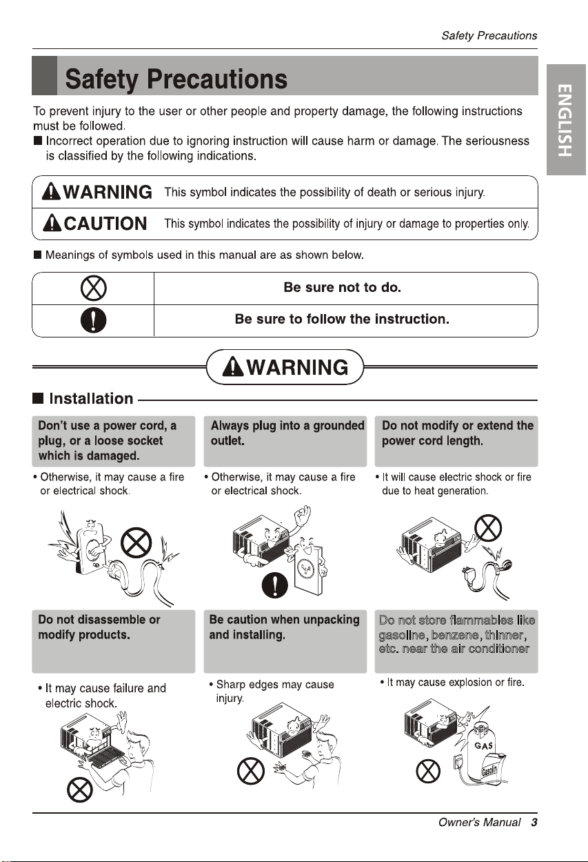
Do not store flammables like
gasoline benzene thinner
etc. near the air conditioner
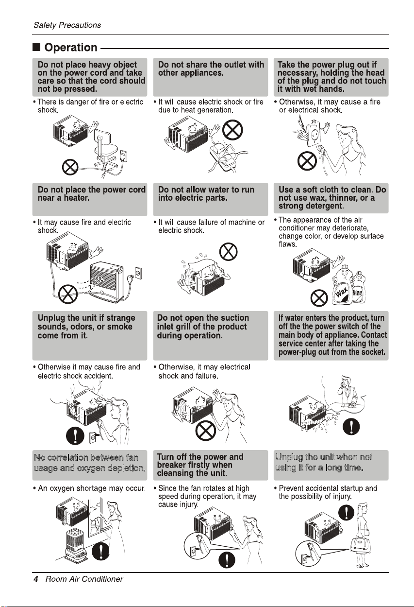
No correlation between fan
usage and oxygen depletion.
Unplug the unit when not
using it for a long time.
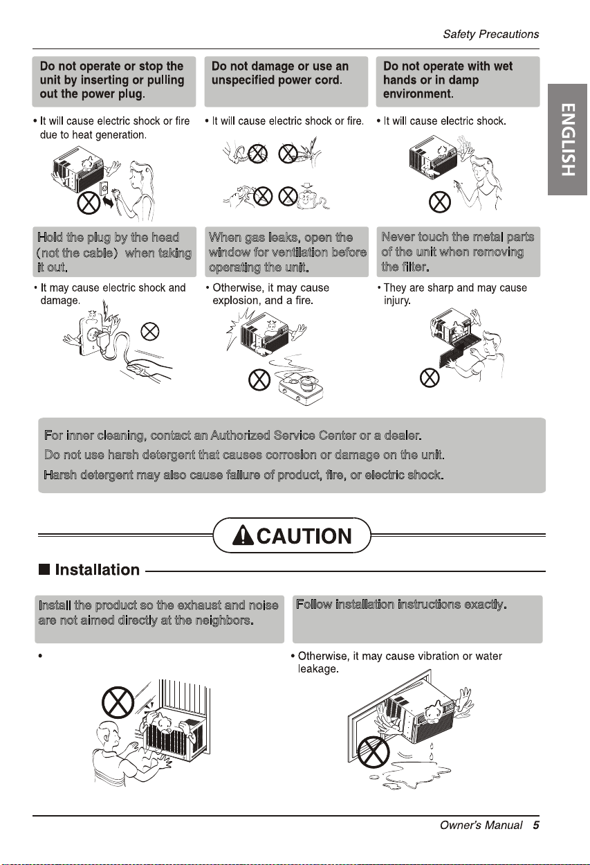
Hold the plug by the head
(not the cable)when taking
it out.
For inner cleaning, contact an Authorized Service Center or a dealer.
Do not use harsh detergent that causes corrosion or damage on the unit.
Harsh detergent may also cause failure of product, fire, or electric shock.
When gas leaks, open the
window for ventilation before
operating the unit.
Never touch the metal parts
of the unit when removing
the filter.
Install the product so the exhaust and noise
are not aimed directly at the neighbors.
Be considerate.
Follow installation instructions exactly.
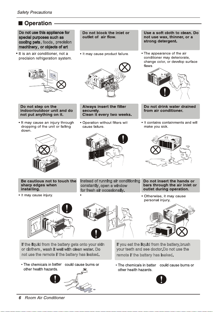
Do not use this appliance for
special purposes such as
,
cooling pets
foods,
precision
machinery,or objects of art
Instead of running air conditioning
constantly
for fresh air occasionally.
You will feel better.
If the liquid from the battery gets onto your skin
or clothers,
wash it well with clean water. Do
not use the remote if the battery has leaked.
y
,open a window
If you eat the liquid from the battery,brush
your teeth and see doctor.Do not use the
remote if the battery has leaked.
y
2. No correlation between fan usage and oxygen depletion.
3.

Introduction
Introduction
Symbols Used in this Manual
This symbol alerts you to the risk of electric shock.
This symbol alerts you to hazards that could cause harm to
the air conditioner.
NOTICE
This symbol indicates special notes.
Features
This appliance should be installed in accordance with the National Electric Code.
Vertical Air Deflector
(Horizontal Louver)
Cabinet
Front Grille Air Filter
Air Intake (Inlet Grille)
Horizontal Air Deflector
(Vertical Louver)
Air Discharge
Remote Controller
Brace
Condenser
Electric Heater
8 Room Air Conditioner
Base Pan
Compressor
Power Cord
Control Board
Evaporator
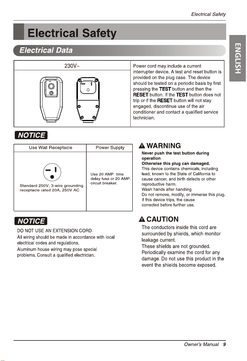
RESET
TEST
should be
Avoid shock hazard. This unit cannot
be user-serviced. Do NOT open the
tamper-resistant sealed portion.
All warranties and performance will
be voided. This unit is not intended
to be used as an ON/OFF switch.
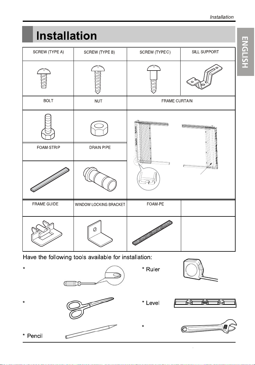
13 EA
3 EA 5 EA
2 EA
2 EA
(Not adhesive backed)
1 EA
2 EA
Phillips head
screwdriver
2 EA
1 EA
1 EA
Left Guide Panel
(Adhesive backed)
1EA
2 EA
Right Guide Panel
Curtain
Scissors or
knife
Adjustable
Wrench
Owner’s Manual 11
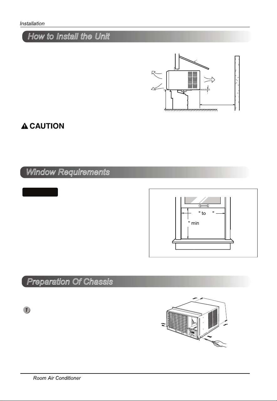
How to Install the Unit
NOTICE
1. To prevent vibration and noise, make sure the unit
is installed securely and firmly
2. Install the unit where the sunlight does not shine
directly on the unit.
3. The outside of the cabinet must extend outward for
Cooled air
Awning
radiation
at least 12" and there should be no obstacles, such
as a fence or wall, within 20" from the back of the
cabinet because it will prevent heat radiation of the
condenser.
Restriction of outside air will greatly reduce the
30"~60"
About1/2"
Over 20"
cooling efficiency of the air conditioner.
All side louvers of the cabinet must remain exposed to the outside of the structure.
4. Install the unit slightly tilted so the back is slightly lower than the front (about 1/2").
This will force condensed water to flow to the outside.
5. Install the unit with the bottom between 30"~60" above the floor level.
Window Requirements
All supporting parts should be secured to firm wood,
masonry, or metal.
This unit is designed for installation in standard
double hung windows with actual opening widths
from 27" to 39".
The top and bottom window sash must open
sufficiently to allow a clear vertical opening of
16" from the bottom of the upper sash to the window stool.
27 39
16
Fence
Heat
Preparation Of Chassis
Remove 4 screws which fasten the cabinet at both
sides and at the back.
12
(Keep the screws for later use.)
Shipping
Screws
(Adhesive backed)
the base pan
(Adhesive backed)
guide
hole
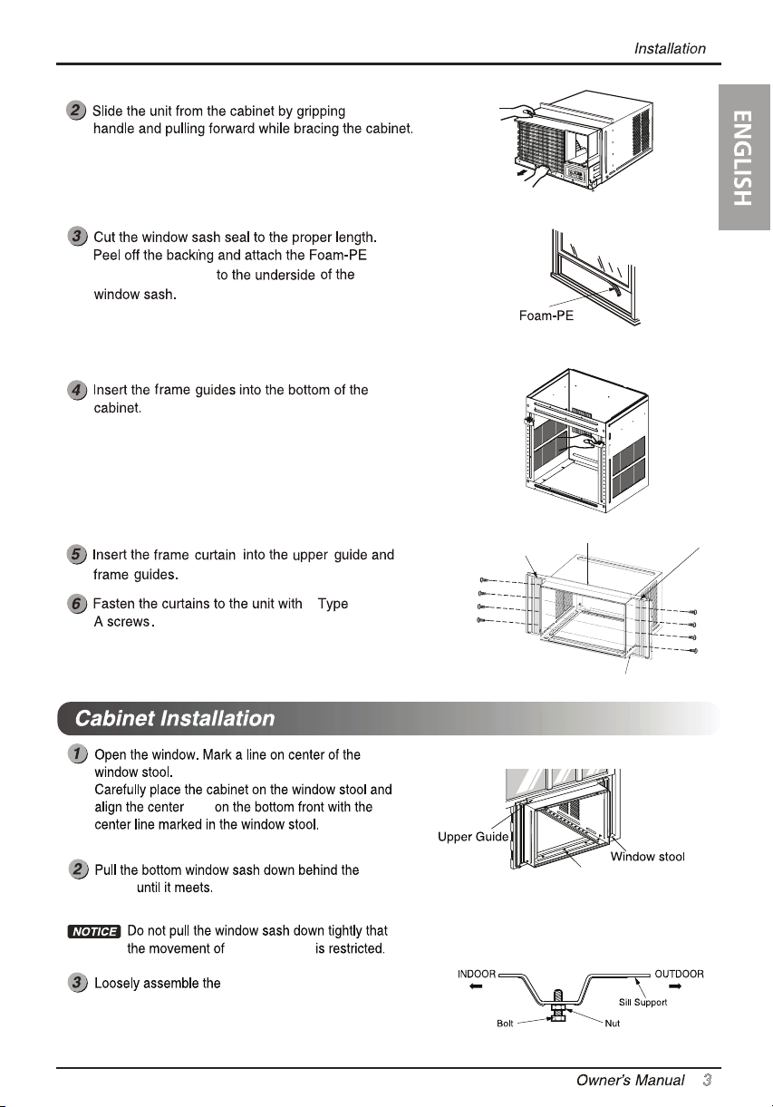
frame curtain
sill support.
Left Guide panel
Upper guide
Right Guide Panel
8
Screws
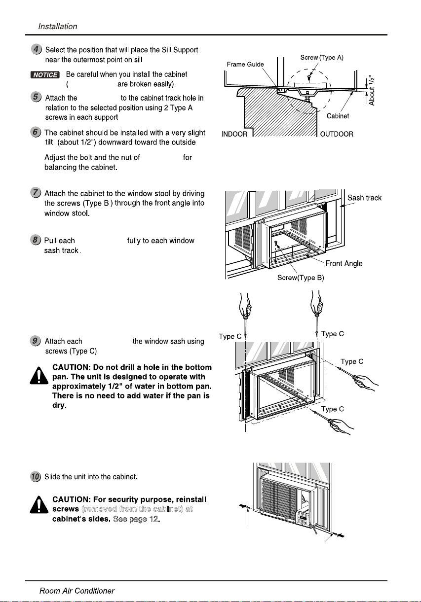
(Type A)
Frame guide
upper
Center hole
13
frame guides
sill support
frame curtain
frame curtain
sill support
14
(removed from the cabinet) at
See page 12.
Screw
Screw
(not adhesive backed)
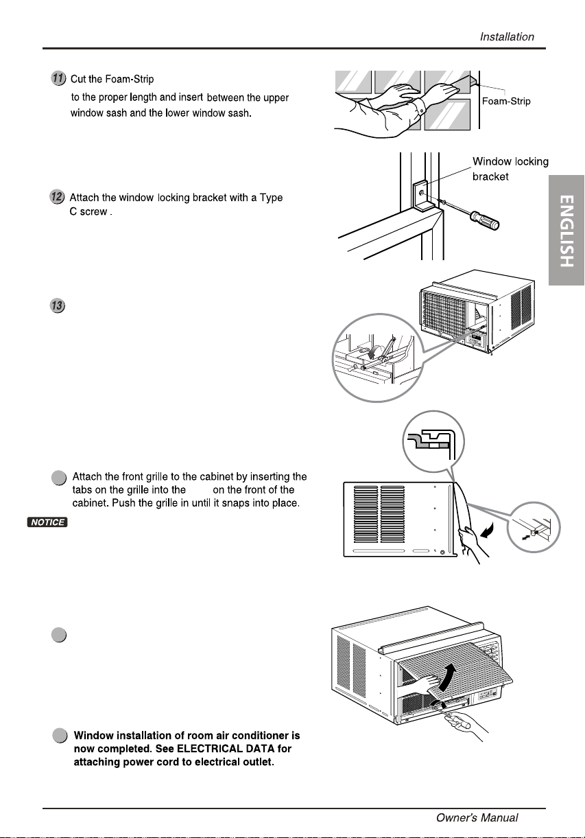
Before installing the front grille, pull out
the vent control lever located above the
unit control knobs, as shown.
(Not adhesive backed)
Type C
14
slots
Guide the lever carefully through the grille as
you push it in.
Lift the inlet grille and secure it with a Type
15
15
A screw through the front grille.
16
16
15
 Loading...