

LG LW1210HR User Manual [en, es]

LG
Window-Type Air Conditioner
OWNER'S MANUAL
LG
website http://www.lgappliances.com
IMPORTANT
Please read through this manual. It contains valuable
information about your air conditioner .This manual may
help save time and money by explaining proper air
conditioner maintenance and preventing improper use.
PRECAUTIONS
Pay close attention to precautions in order to prevent
potential hazards and damage from misuse or improper
installation. LG is not responsible for any damages
caused by misuse of the air conditioner.
MODELS, MODELOS: LW1210HR
ENGLISH ESPAÑOL
2 Room Air Conditioner
Window-Type Air Conditioner Owner’s Manual
TABLE OF CONTENTS
FOR YOUR RECORDS
Write the model and serial numbers here:
Model #
Serial #
You can find them on a label on the side of each unit.
Dealer's Name
Date Purchased
■ Staple your receipt to this page in the event you need it
to prove date of purchase or for warranty issues.
READ THIS MANUAL
Inside you will find many helpful hints on how to use and
maintain your air conditioner properly. Just a little preventive
care on your part can save you a great deal of time and
money over the life of your air conditioner.
You'll find many answers to common problems in the chart
of troubleshooting tips. If you review our chart of
Troubleshooting Tips first, you may not need to call for
service at all.
PRECAUTION
• Contact the authorized service technician for repair
or maintenance of this unit.
• Contact the installer for installation of this unit.
• The air conditioner is not intended for use by young
children or invalids without supervision.
• Young children should be supervised to ensure that
they do not play with the air conditioner.
• When the power cord is to be replaced, replacement
work shall be performed by authorized personnel only
using only genuine replacement parts.
• Installation work must be performed in accordance
with the National Electric Code by qualified and
authorized personnel only.
Safety Precautions..........................3
Before Operation.............................7
Introduction ....................................8
Electrical Safety ..............................9
Installation ....................................11
Operating Instructions .................16
Maintenance and Service ............20
Owner’s Manual 3
ENGLISH
Safety Precautions
Safety Precautions
To prevent injury to the user or other people and property damage, the following instructions
must be followed.
■ Incorrect operation due to ignoring instruction will cause harm or damage. The seriousness
is classified by the following indications.
■ Meanings of symbols used in this manual are as shown below.
WARNING
CAUTION
This symbol indicates the possibility of death or serious injury.
This symbol indicates the possibility of injury or damage to properties only.
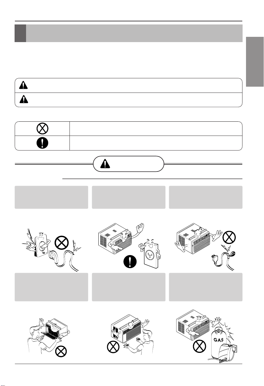
WARNING
■ Installation
Be sure not to do.
Be sure to follow the instruction.
Don’t use a power cord, a
plug or a loose socket which
is damaged.
• Otherwise, it may cause a fire
or electrical shock.
Always plug into a grounded
outlet.
• Otherwise, it may cause a fire
or electrical shock.
Do not modify or extend the
power cord length.
• It will cause electric shock or fire
due to heat generation.
Do not disassemble or
modify products.
• It may cause failure and
electric shock.
Be caution when unpacking
and installing.
• Sharp edges may cause
injury.
Do not use the power cord near
flammable gas or combustibles
such as gasoline, benzene,
thinner, etc.
• It may cause explosion or fire.
4 Room Air Conditioner
Safety Precautions
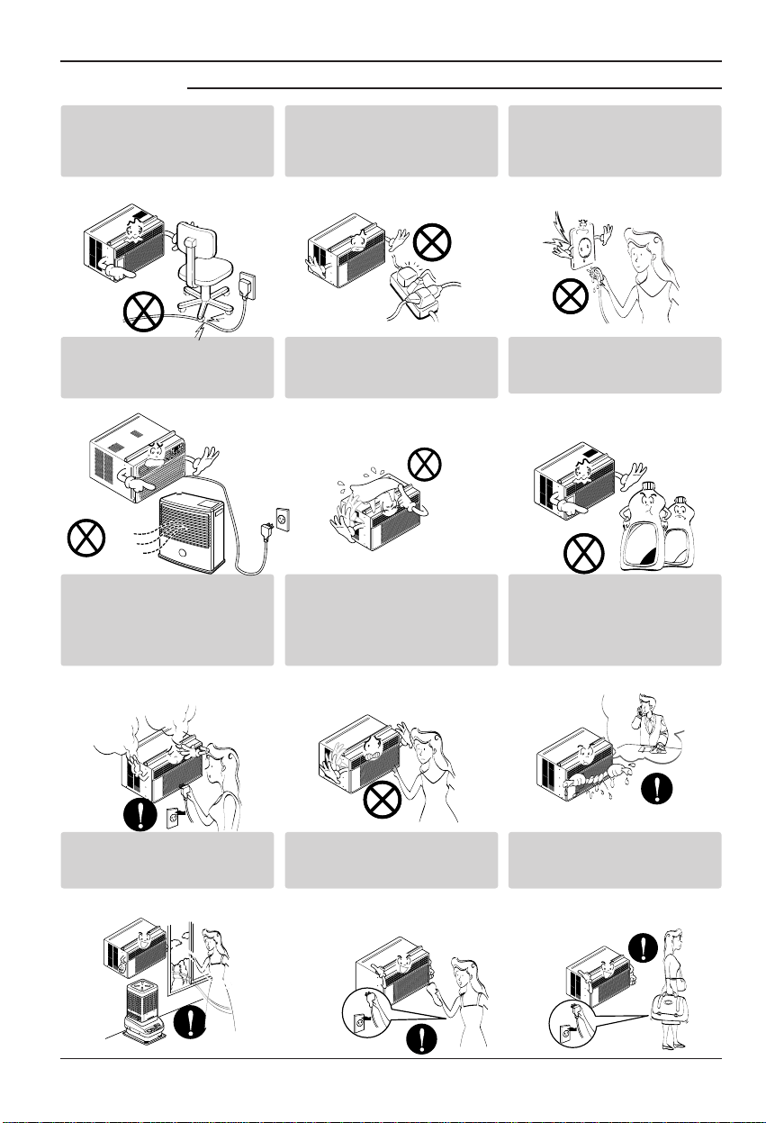
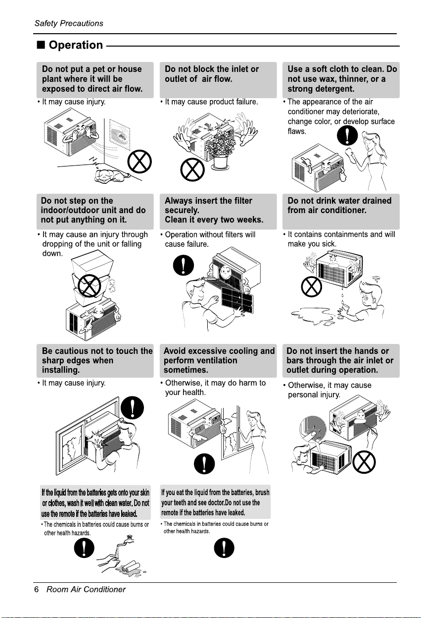
■ Operation
Do not place the power cord
near a heater.
• It may cause fire and electric
shock.
Do not allow water to run
into electric parts.
• It will cause failure of machine or
electric shock.
Use a soft cloth to clean. Do
not use wax, thinner, or a
strong detergent.
• The appearance of the air
conditioner may deteriorate,
change color, or develop surface
flaws.
Ventilate the room well when
using this appliance
together with a stove, etc.
• An oxygen shortage may occur.
Turn off the power and
breaker firstly when
cleansing the unit.
• Since the fan rotates at high
speed during operation, it may
cause injury.
Turn off the main power
switch when not using it for
a long time.
• Prevent accidental startup and
the possibility of injury.
Unplug the unit if strange
sounds, odors, or smoke
come from it.
• Otherwise it may cause fire and
electric shock accident.
Do not open the suction
inlet grill of the product
during operation.
• Otherwise, it may electrical
shock and failure.
If water enters the product, turn
off the the power switch of the
main body of appliance. Contact
service center after taking the
power-plug out from the socket.
Do not place heavy object
on the power cord and take
care so that the cord should
not be pressed.
• There is danger of fire or electric
shock.
Do not share the outlet with
other appliances.
• It will cause electric shock or fire
due to heat generation.
Take the power plug out if
necessary, holding the head
of the plug and do not touch
it with wet hands.
• Otherwise, it may cause a fire
or electrical shock.
Thinner
Wax
Owner’s Manual 5
ENGLISH
Safety Precautions
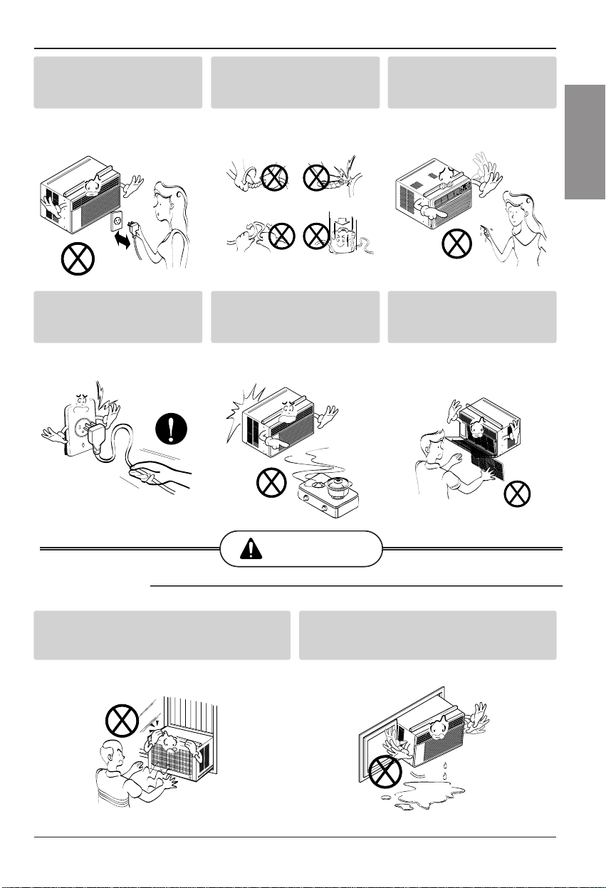
CAUTION
■ Installation
Do not operate or stop the
unit by inserting or pulling
out the power plug.
• It will cause electric shock or fire
due to heat generation.
Do not damage or use an
unspecified power cord.
• It will cause electric shock or fire.
Do not operate with wet
hands or in damp
environment.
• It will cause electric shock.
Hold the plug by the head
when taking it out.
• It may cause electric shock and
damage.
When gas leaks, open the
window for ventilation
before operating the unit.
• Otherwise, it may cause
explosion, and a fire.
Never touch the metal parts
of the unit when removing
the filter.
• They are sharp and may cause
injury.
Install the product so that the noise or hot
wind from the outdoor unit may not cause
any damage to the neighbors.
• Otherwise, it may cause dispute with the
neighbors.
Keep level parallel in installing the product.
• Otherwise, it may cause vibration or water
leakage.

Before Operation
Owner’s Manual 7
ENGLISH
Before Operation
1. Contact an installation specialist for installation.
2. Plug in the power plug properly.
3. Use a dedicated circuit.
4. Do not use an extension cord.
5. Do not start/stop operation by plugging/unplugging the power cord.
6. If the cord/plug is damaged, replace it with only an authorized replacement
part.
1. Being exposed to direct airflow for an extended period of time could be
hazardous to your health. Do not expose occupants, pets, or plants to direct
airflow for extended periods of time.
2. Due to the possibility of oxygen deficiency, ventilate the room when used
together with stoves or other heating devices.
3. Do not use this air conditioner for non-specified special purposes (e.g.
preserving precision devices, food, pets, plants, and art objects). Such usage
could damage the items.
1. Do not touch the metal parts of the unit when removing the filter. Injuries can
occur when handling sharp metal edges.
2. Do not use water to clean inside the air conditioner. Exposure to water can
destroy the insulation, leading to possible electric shock.
3. When cleaning the unit, first make sure that the power and breaker are turned
off. The fan rotates at a very high speed during operation. There is a
possibility of injury if the unit’s power is accidentally triggered on while
cleaning inner parts of the unit.
For repair and maintenance, contact your authorized service dealer.
Preparing for Operation
Usage
Cleaning and Maintenance
Service
8 Room Air Conditioner
Introduction
This symbol alerts you to the risk of electric shock.
This symbol alerts you to hazards that could cause harm to
the air conditioner.
This symbol indicates special notes.
NOTICE
This appliance should be installed in accordance with the National Electric Code.
Introduction
Symbols Used in this Manual
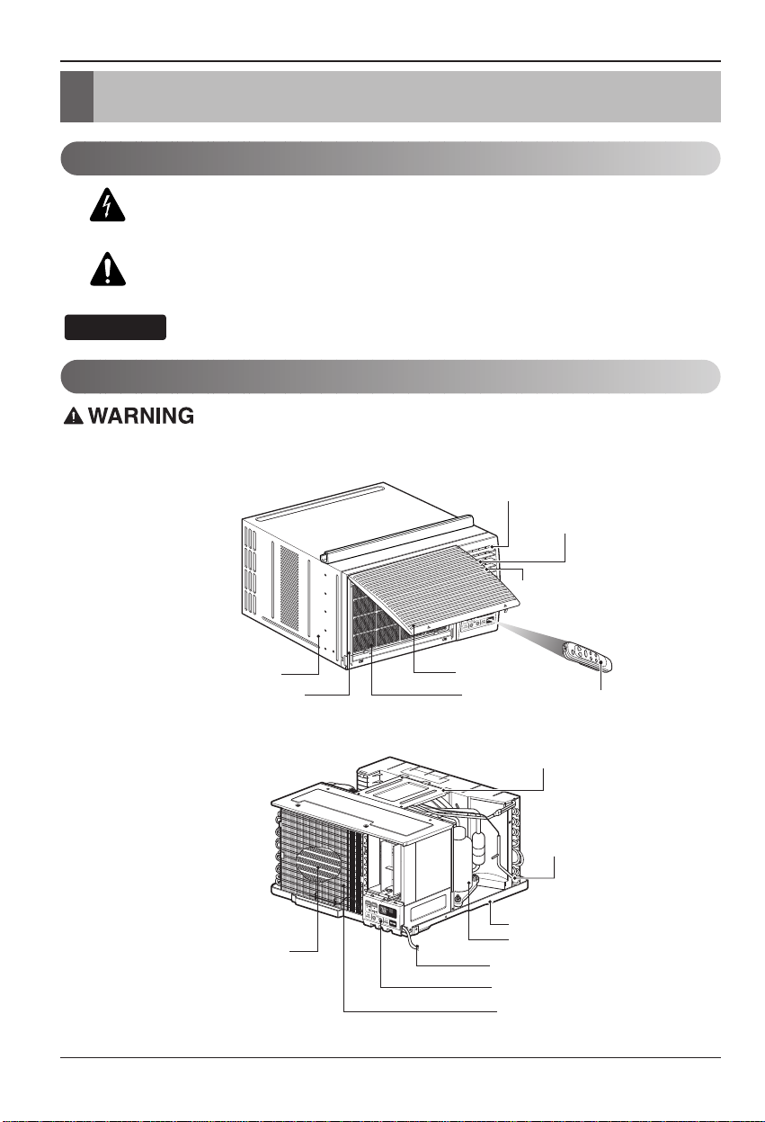
Features
Vertical Air Deflector
(Horizontal Louver)
Horizontal Air Deflector
(Vertical Louver)
Cabinet
Front Grille Air Filter
Electric Heater
Air Discharge
Air Intake(Inlet Grille)
Remote Controller
Brace
Condenser
Base Pan
Compressor
Power Cord
Control Board
Evaporator
Electrical Safety
ENGLISH
Electrical Safety
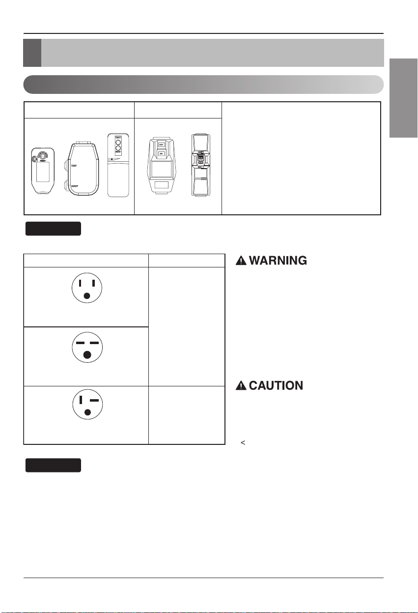
Electrical Data
115V~ 230V~
NOTICE
The shape may be different according to its model.
Use Wall Receptacle Power Supply
Standard 125V, 3-wire grounding
receptacle rated 15A, 125V AC
Standard 250V, 3-wire grounding
receptacle rated 15A, 250V AC
Use 15 AMP. time
delay fuse or 15 AMP.
circuit breaker.
Power cord may include a current
interrupter device. A test and reset button is
provided on the plug case. The device
should be tested on a periodic basis by first
pressing the TEST button and then the
RESET button. If the TEST button does not
trip or if the RESET button will not stay
engaged, discontinue use of the air
conditioner and contact a qualified service
technician.
Never push the test button during
operation
Otherwise this plug can damaged.
This device contains chemical, including
lead, known to the State of California to
cause cancer, and birth defects or other
reproductive harm.
Wash hands after handling.
Do not remove, modify or immerse this plug.
If this device trips, the cause it to be
corrected before further use.
Use 20 AMP. time
delay fuse or 20 AMP.
Standard 250V, 3-wire grounding
receptacle rated 20A, 250V AC
circuit breaker.
NOTICE
DO NOT USE AN EXTENSION CORD on 230,
208, and 230/208 Volt units.
All wiring should be made in accordance with local
electrical codes and regulations.
Aluminum house wiring may pose special
problems. Consult a qualified electrician.
The conductors inside this cord are
surrounded by shields, which monitor
leakage current.
These shields are not grounded.
<
Periodically examine the cord for any
damage. Do not use this product in the
event the shields become exposed.
Avoid shock hazard, this unit can not
be user serviced opening the tamper
resistant. Sealed portion of the unit
voids all warranties and performance
claims. This unit not intended for use
as an on-off switch.
Owner’s Manual 9
10 Room Air Conditioner
Electrical Safety
Electrical Safety
IMPORTANT
(PLEASE READ CAREFULLY)
FOR THE USER'S PERSONAL SAFETY,THIS
APPLIANCE MUST BE PROPERLY GROUNDED
The power cord of this appliance is equipped with a
three-prong (grounding) plug. Use this with a standard
three-slot (grounding) wall power outlet to minimize the
hazard of electric shock. The customer should have the
wall receptacle and circuit checked by a qualified
electrician to make sure the receptacle is properly
grounded.
DO NOT CUT OR REMOVE THE THIRD (GROUND)
PRONG FROM THE POWER PLUG.
A. SITUATIONS WHEN THE APPLIANCE WILL BE
DISCONNECTED OCCASIONALLY:
Because of potential safety hazards, we strongly
discourage the use of an adapter plug. However, if you
wish to use an adapter, a TEMPORARY CONNECTION
may be made. Use UL-listed adapter, available from
most local hardware stores.
The large slot in the adapter must be aligned with the
large slot in the receptacle to assure a proper polarity
connection.
:
Attaching the adapter ground terminal to the wall
receptacle cover screw does not ground the appliance
unless the cover screw is metal, and not insulated, and
the wall receptacle is grounded through the house
wiring. The customer should have the circuit checked
by a qualified electrician to make sure the receptacle
is properly grounded.
Disconnect the power cord from the adapter, using one
hand on each. Otherwise, the adapter ground terminal
might break. DO NOT USE the appliance with a broken
adapter plug.
B. SITUATIONS WHEN THE APPLIANCE WILL BE
DISCONNECTED OFTEN.
Do not use an adapter plug in these situations.
Unplugging the power cord frequently can lead to an
eventual breakage of the ground terminal. The wall
power outlet should be replaced by a three-slot
(grounding) outlet instead.
USE OF EXTENSION CORDS
Because of potential safety hazards, we strongly
discourage the use of an extension cord. However, if
you wish to use an extension cord, use a CSA
certified/UL-listed 3-wire (grounding) extension cord,
rated at 15A, 125V.
Owner’s Manual 11
ENGLISH
Installation
Installation
How to Install the Unit
Window Requirements
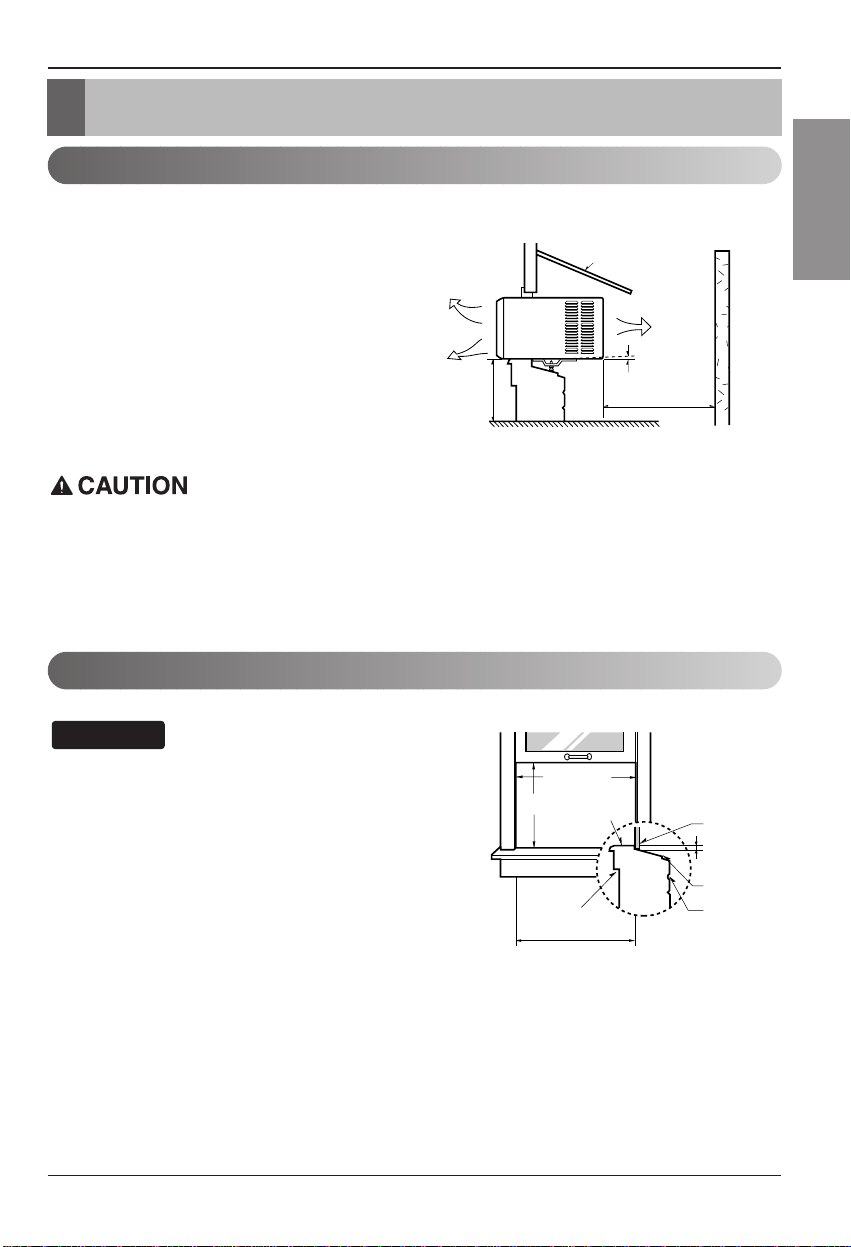
1. To prevent vibration and noise, make sure
the unit is installed securely and firmly
2. Install the unit where the sunlight does not
shine directly on the unit.
3. The outside of the cabinet must extend
outward for at least 12" and there should
be no obstacles, such as a fence or wall,
within 20" from the back of the cabinet
because it will prevent heat radiation of the
condenser.
Restriction of outside air will greatly
reduce the cooling efficiency of the air
conditioner.
All side louvers of the cabinet must remain exposed to the outside of the structure.
4. Install the unit a little slanted so the back is slightly lower than the front(about 1/2").
This will force condensed water to flow to the outside.
5. Install the unit with the bottom about 30"~60" above the floor level.
All supporting parts should be secured to firm wood,
masonry, or metal.
This unit is designed for installation in standard
double hung windows with actual opening widths
from 27" to 39".
The top and bottom window sash must open
sufficiently to allow a clear vertical opening of
16" from the bottom of the upper sash to the window stool.
NOTICE
About 1/2"
30"~60"
Awning
Cooled air
Fence
Over 20"
Heat
radiation
Interior wall
Stool
16" min
27" to 39"
1
/2" to 11/4"
Offset
Sill
Exterior
23
5
/8" min
(Without frame curtain)
12 Room Air Conditioner
Installation
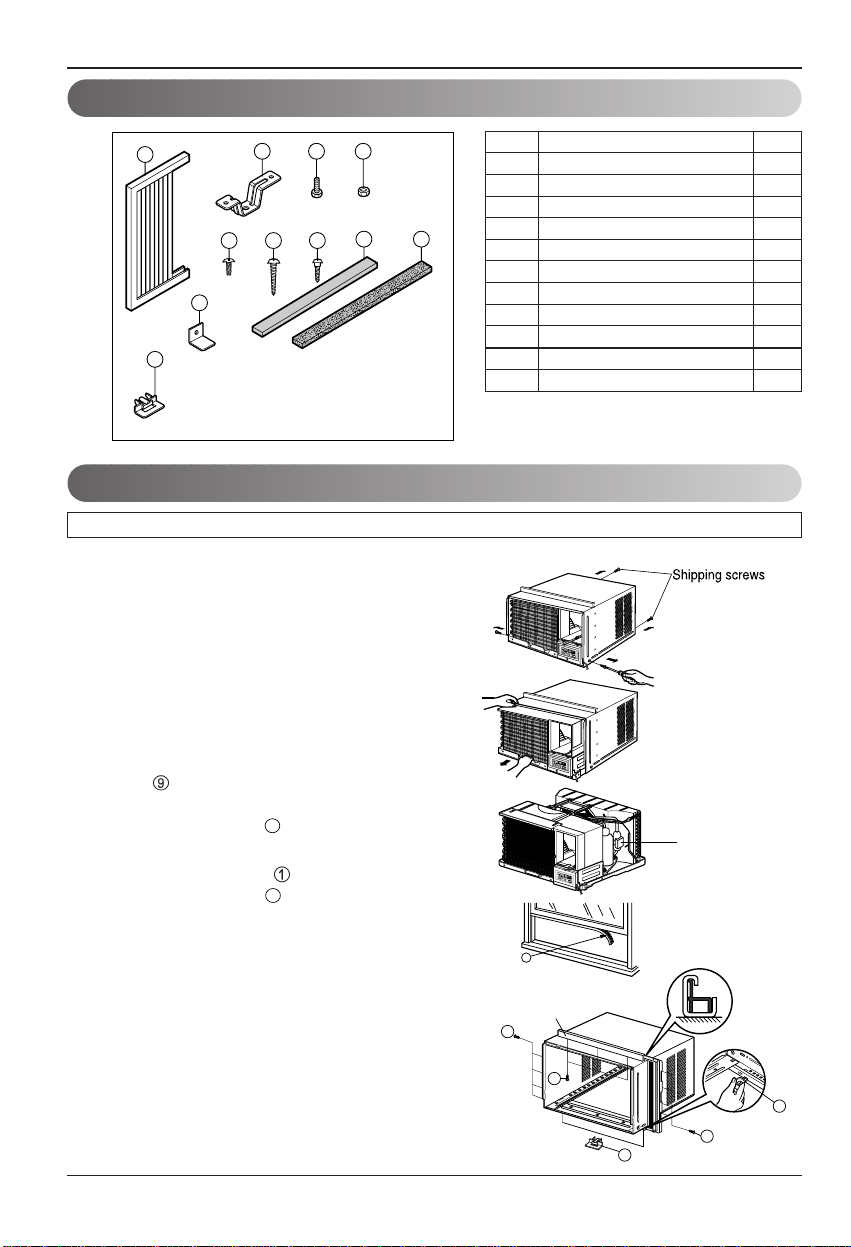
Installation Kits Contents
Suggested Tool Requirements
PREPARATION OF CHASSIS
1. Remove the screws which fasten the cabinet
at both sides and at the back.
2. Slide the unit from the cabinet by gripping the
base pan handle and pulling forward while
bracing the cabinet.
3. Remove EPS Material.
4. Cut the window sash seal to the proper
length. Peel off the backing and attach the
foam-pe to the underside of the window
sash.
5
. Insert the frame guides into the bottom of
the cabinet.
6
. Insert the Frame Curtain
into the upper
guide and frame guides .
7
. Fasten the curtains to the unit with 4 Type A
screws.
SCREWDRIVER(+, -), RULER, KNIFE, HAMMER, PENCIL, LEVEL
NO. NAME OF PARTS Q'TY
1 FRAME CURTAIN 2
2 SILL SUPPORT 2
3 BOLT 2
4 NUT 2
5 SCREW(TYPE A) 13
6 SCREW(TYPE B) 3
7 SCREW(TYPE C) 5
8 FOAM-STRIP 1
9 FOAM-PE 1
10 FRAME GUIDE 2
11
WINDOW LOCKING BRACKET
1
1
2 3 4
765
8 9
1
1
0
1
10
10
EPS Material
9
(Type A)
Upper guide
5
5
10
10
5
(Type A)
Upper Guide
Window Sash
Window stool
Front Angle
Upper guide
Frame Curtain
1
Foam-pe
Foam-pe
9
Cabinet
INDOOR OUTDOOR
INDOOR OUTDOOR
Sash track
Front Angle
Cabinet
About
1
/2"
About
1
/2"
Sill Support
2
Nut
4
Bolt
3
Frame Guide
10
Screw(Type B)
6
Screw(Type B)
6
Sill support
2
Sill support
2
Screw(Type A)
5
Owner’s Manual 13
ENGLISH
Installation
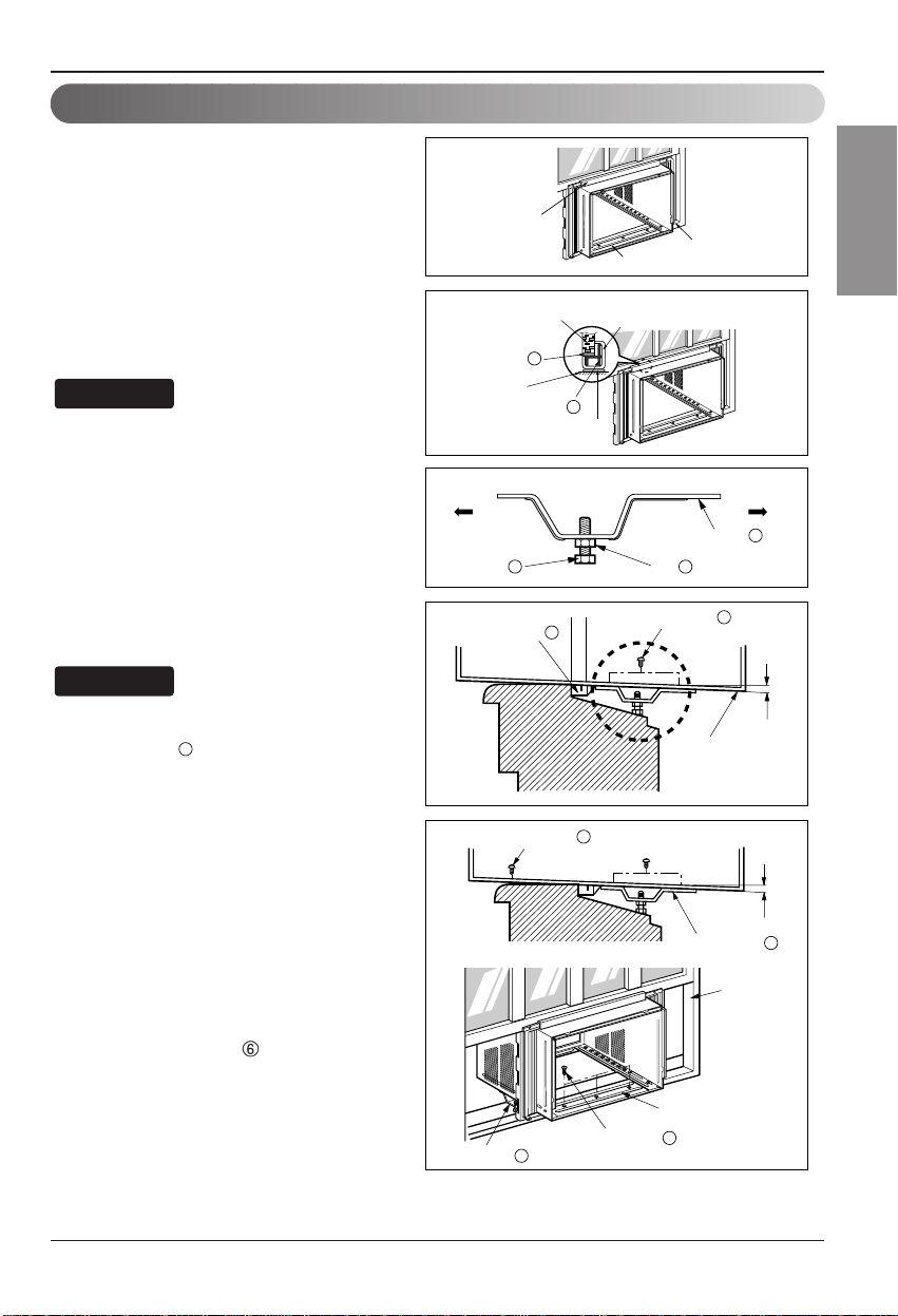
Cabinet Installation
1. Open the window. Mark a line on
center of the window stool(or desired
air conditioner location).
Carefully place the cabinet on the
window stool and align the center
mark on the bottom front with the
center line marked in the window
stool.
2. Pull the bottom window sash down
behind the upper guide until it meets.
Do not pull the window sash down so
tightly that the movement of Frame
Curtain is restricted.
3. Loosely assemble the sill support
using the parts in Fig. 3.
4. Select the position that will place the
sill support near the outer most point
on sill (See Fig. 4)
Be careful when you install the cabinet
(frame guides are broken so easily).
5. Attach the sill support to the cabinet
track hole in relation to the selected
position using 2 Type A screws in
each support(See Fig. 4).
6. The cabinet should be installed with a
very slight tilt(about 1/2") downward
toward the outside (See Fig. 5).
Adjust the bolt and the nut of sill
support for balancing the cabinet.
7. Attach the cabinet to the window stool
by driving the screws
(Type B:
Length sixteen millimeters and
below.) through the front angle into
window stool.
8. Pull each Frame curtain fully to each
window sash track, and repeat step 2.
NOTICE
NOTICE
Fig. 1
Fig. 2
Fig. 3
Fig. 4
Fig. 5
10
Type C
7
Screw(Type A)
Screw(Type A)
Power cord
Foam-Strip
8
Window locking bracket
11
14 Room Air Conditioner
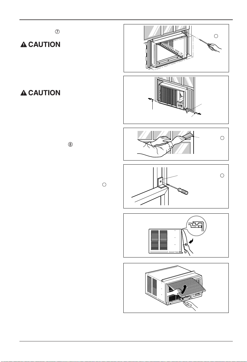
Installation
9. Attach each Frame curtain the window sash
using screws (Type C).(See Fig. 6)
Do not drill a hole in the bottom pan.
The unit is designed to operate with
approximately 1/2" of water in bottom pan.
10. Slide the unit into the cabinet.(See Fig. 7)
For security purpose, reinstall screws(Type A) at
cabinet's sides.
11. Cut the foam-strip to the proper length
and insert between the upper window
sash and the lower window sash.
(See Fig. 8)
12. Attach the window locking bracket with
a type C screw. (See Fig. 9)
13. Attach the front grille to the cabinet by
inserting the tabs on the grille into the
tabs on the front of the cabinet. Push the
grille in until it snaps into place. (See
Fig.10)
14. Lift the inlet grille and secure it with a type
A screw through the front grille.
(See Fig. 11)
15. Window installation of room air conditioner
is now completed. See ELECTRICAL DATA
for attaching power cord to electrical outlet.
Fig. 6
Fig. 7
Fig. 8
Fig. 9
Fig. 10
Fig. 11
11
 Loading...