

LG LV-B2461CL, LV-B2461HL, LV-B1861HL, LV-B1861CL, LV-2461HL Service Manual
...
Room Air Conditioner
(Convertible Type)
SERVICE MANUAL
MODEL: LV-B2461CL/ 2461HL
LV-B1861CL/ 1861HL

Contents
Functions .................................................................................................................................3
Product Specifications (Cooling Only)..................................................................................5
Product Specifications (Cooling & Heating).........................................................................6
Dimensions..............................................................................................................................7
Refrigeration Cycle Diagram..................................................................................................9
Wiring Diagram......................................................................................................................11
Operation Details ..................................................................................................................13
Display Function ...................................................................................................................21
Self-diagnosis Function........................................................................................................21
Installation .............................................................................................................................22
Operation ...............................................................................................................................39
Disassembly of the parts (Indoor Unit) ...............................................................................41
2-way, 3-way Valve.................................................................................................................45
Cycle Troubleshooting Guide...............................................................................................52
Electronic Parts Troubleshooting Guide.............................................................................53
Electronic control device......................................................................................................57
Schematic Diagram...............................................................................................................58
Exploded View and Replacement Parts List.......................................................................59
–2–
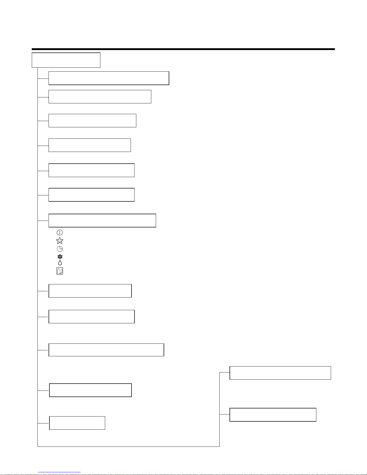
Functions
•Room temperature sensor. (Thermistor)
•Maintains the room temperature in accordance with the Setting Temp.
•Indoor fan is delayed for 5 seconds at the starting.
•Restarting is inhibited for approx. 3 minutes.
•High, Med, Low, Chaos
--- Lights up in operation
--- Lights up in Sleep Mode
--- Lights up in Timer Mode
--- Lights up in Deice Mode or Hot Start Mode (only Heating Model)
--- Lights up during compressor running
(only Cooling Model)
•Intermittent operation of fan at low speed.
•The fan is switched to low(Cooling), med(Heating) speed.
•The unit will be stopped after 1, 2, 3, 4, 5, 6, 7 hours.
•The fan is switched to intermittent or irregular operation
•The fan speed is automatically switched from high to low
speed.
•The louver can be set at the desired position or swing
up and down, right and left (not on all models) automatically.
•The setting temperature, indoor fan speed and desired
operation made are automatically set by fuzzy rule.
Indoor Unit
Operation ON/OFF by Remote controller
Sensing the Room Temperature
Room temperature control
Starting Current Control
Time Delay Safety Control
Indoor Fan Speed Control
Operation indication Lamps (LED)
Soft Dry Operation Mode
•Both the indoor and outdoor fan
stops during deicing.
•Hot start after deice ends.
•The indoor fan stops until the
evaporator piping temperature
will be reached at 28°C.
Deice (defrost) control (Heating)
Hot-start Control (Heating)
Sleep Mode Auto Control
Natural Air Control by CHAOS Logic
Airflow Direction Control
Auto Operation
–3–
–4–
Soft Dry Operation Mode.( )
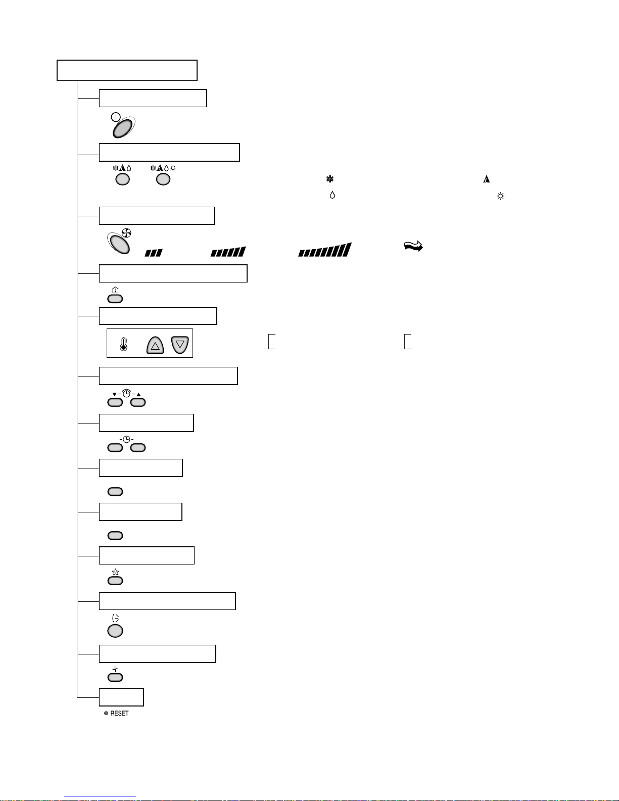
Remote Controller
Operation ON/OFF
Reset
Operation Mode Selection
Fan Speed Selection
Room Temperature Display
Temperature Setting
Setting the Time or Timer
Timer Selection
Timer Setting
Timer Cancel
Sleep Operation
Airflow Direction Control
(Cooling
model only)
(Heating
model only)
TEMPERATURE
LOW HIGH
(Low) (Med) (High) (CHAOS)
Cooling Operation Mode.( )
Heating Operation Mode.( )
Auto Operation Mode.( )
Fan Operation Mode
ON OFF
SET
CANCEL
: High:39°C ↔ LOW:11°C
: OFF, ON, OFF ↔ ON
: Cancel Sleep Mode, Timer ON or Timer OFF.
: 1, 2, 3, 4, 5, 6, 7hr, Off Timer
: Fan Operates without cooling. (Cooling model only)
Cooling Heating
Down to 18°C
Up to 30°C,
Down to 16°C
Up to 30°C,
Product Specifications (Cooling Only)
Model Name
Item Unit
Cooling Capacity Btu/h(kcal/h) 18,000(4,536) 24,000(6,048)
Moisture Removal ℓ/h 2.5 3.5
Power Source
ø
, V, Hz
1ø, 220-240V, 50Hz
Indoor 14.0 16.0
Outdoor 50 50
Input W 1,935 2,500
Running Current A 9.0 11.9
E.E.R. Btu/h-W 9.3 9.6
Indoor 1,200 x 205 x 615
Outdoor 870 x 655 x 320
Indoor 30
Outdoor 57 57
Refrigerant (R-22) g 880 1,550
Airflow Direction Control (Up & Down)
Remocon Type L.C.D Wireless
Liquid 1/4" (6.35) 1/4" (6.35)
Gas 1/2" (12.7) 5/8" (15.88)
Sleeping Operation
Drain Hose
Connecting Wire 0.75mm
2
Main Power Cable 1.5mm
2
2.5mm2
(2.0mm
2
:for the Middle East)
Time Delay Safety Function
Air Circulation
Soft Dry
Fan Speed (Indoor) 3 (Hi, Med, Low)
Timer 24Hrs
Self-Diagnosis
Auto-Restart
Air Circulation m3/min
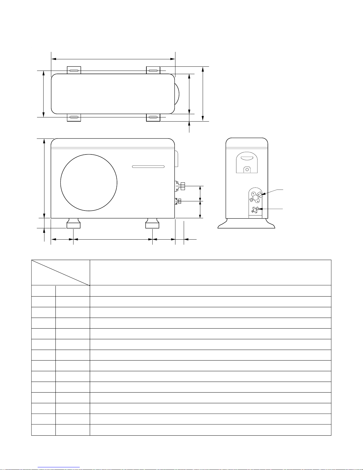
Dimensions
(W×H×D)
Net. Weight
mm
kg
LV-B1861CL LV-B2461CL
–5–
Service Valve &
Connecting Tube
Product Specifications (Cooling & Heating)
–6–
Model Name
Item Unit
Cooling Capacity Btu/h(kcal/h) 19,000(4,788) 24,000(6,048)
Heating Capacity Btu/h(kcal/h) 20,000(5,040) 24,000(6,048)
Moisture Removal ℓ/h 2.5 3.5
Power Source
ø
, V, Hz
1
ø
, 220-240V~, 50Hz
Indoor 14.5 16
Outdoor 45 50
Input Cooling 1,950 2,670
Heating 1,860 2,570
Running Current Cooling 8.9 12.3
Heating 8.5 11.9
E.E.R.(Cooling) Btu/h-W 9.74 8.98
C.O.P.(Heating) w/w 3.15 2.73
Indoor 1,200 x 205 x 615
Outdoor 870 x 655 x 320
Indoor 30
Outdoor 58 58
Refrigerant (R-22) g 1,310 1,390
Airflow Direction Control (Up & Down)
Remocon Type L.C.D Wireless
Liquid 1/4" (6.35) 1/4" (6.35)
Gas 1/2" (12.7) 5/8"(15.88)
Sleeping Operation
Drain Hose
Connecting Wire 0.75mm
2
Main Power Cable 1.5mm
2
2.5mm2
(2.0mm
2
:for the Middle East)
Time Delay Safety Function
Air Circulation
Soft Dry
Fan Speed (Indoor) 3 (Hi, Med, Low)
Timer 24Hrs
Self-Diagnosis
Auto-Restart
Air Circulation m3/min
W
A
Dimensions
(W×H×D)
Net. Weight
mm
kg
LV-B1861HL
LV-B2461HL
Service Valve &
Connecting Tube
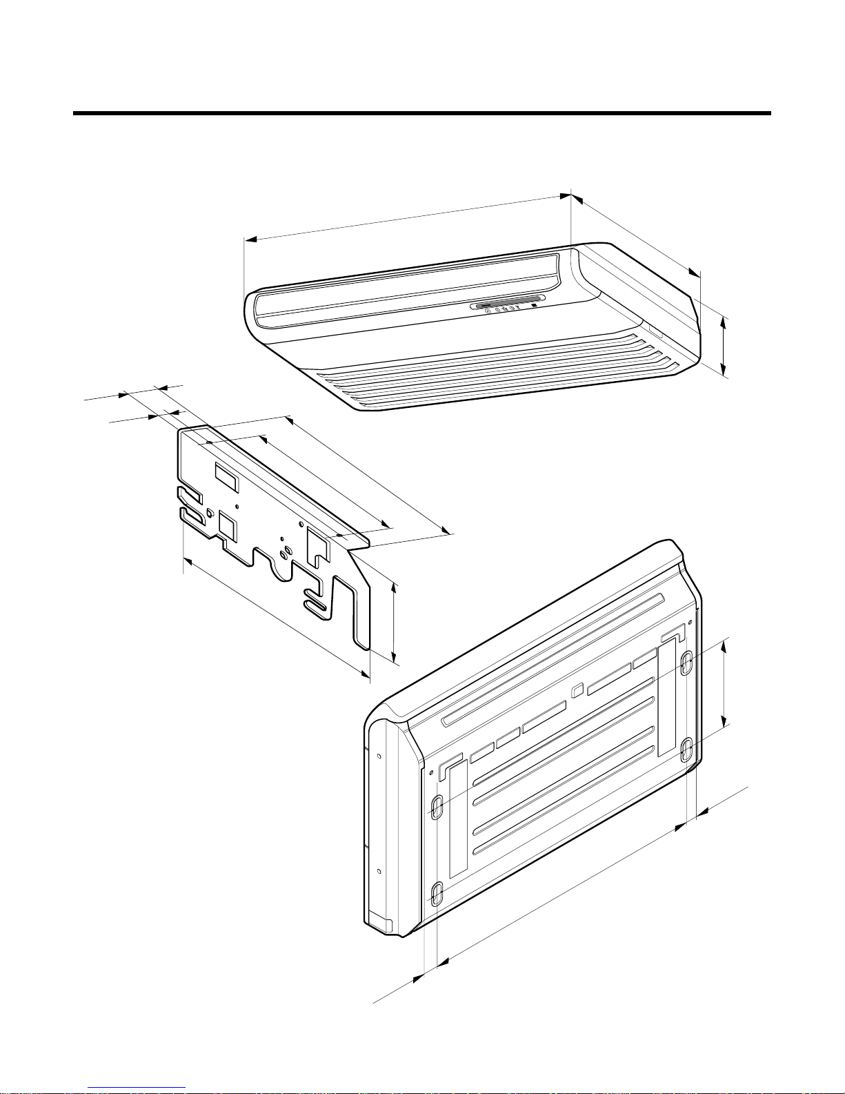
Dimensions
(1) Indoor Unit
250mm
36mm
36mm
1076mm
1200mm
205mm
615mm
392mm
265mm
468mm
R
63mm
38mm
175mm
(Installation Plate)
(Rear Side)
–7–
(2) Outdoor Unit
Gas side
3-way valve
Liquid side
3-way valve
W
L6L7 L8 L9
L4
L11
L10
D
L1
L2
L5
L3
MODEL
DIM
W mm 870
H mm 655
D mm 320
L1 mm 370
L2 mm 25
L3 mm 340
L4 mm 630
L5 mm 25
L6 mm 546
L7 mm 162
L8 mm 162
L9 mm 54
L10 mm 74.5
L11 mm 79
–8–
LV-B1861CL/HL
LV-B2461CL/HL
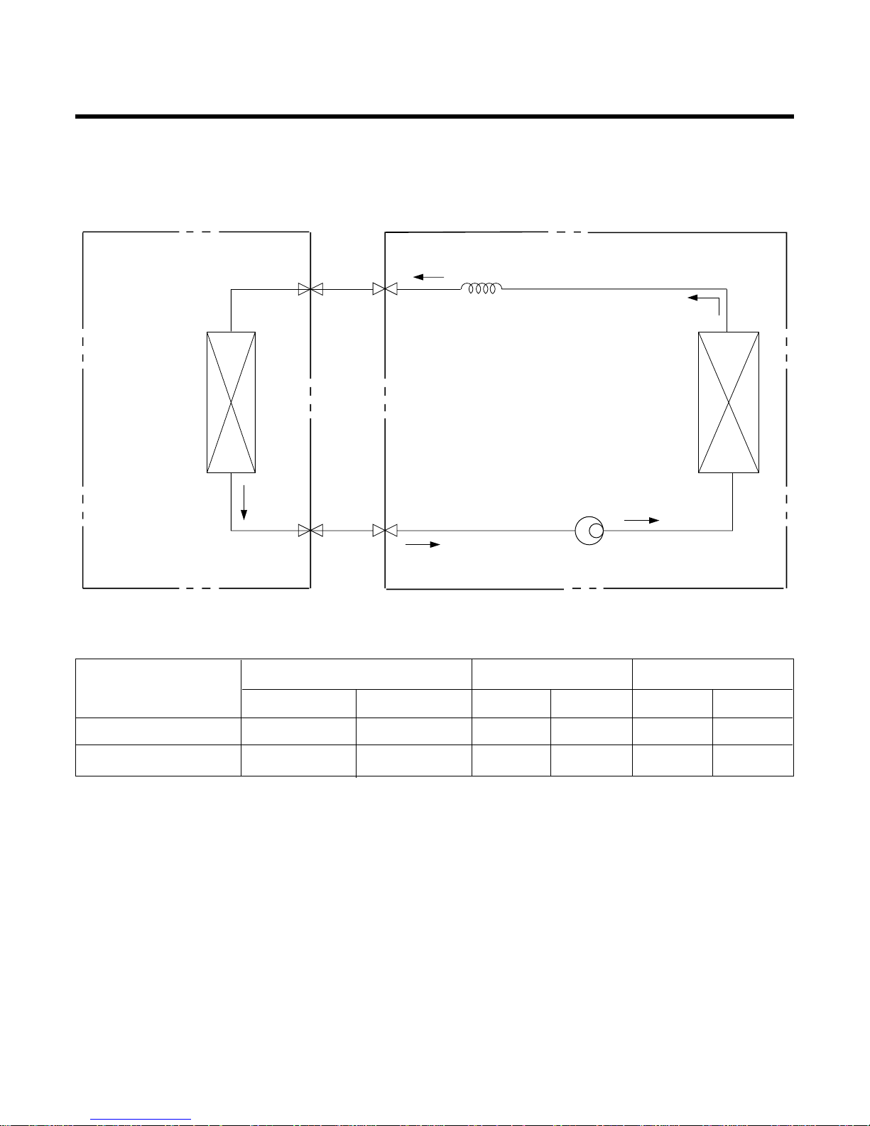
Refrigeration Cycle Diagram
• LV-B1861CL
• LV-B2491CL
For installation over rated distance, 30g of refrigerant should be added for each meter.
ex) When installed at a distance of 15m, 300g of refrigerant should be added.
(15-5) x 30g = 300g
Pipe size(Diameter:) Piping length(m) Elevation(m)
MODEL
Gas Liquid Rated Max Rated Max
LV-B1861CL 1/2" 1/4" 5 15 5 8
LV-B2461CL 5/8" 1/4" 5 20 5 8
INDOOR UNIT OUTDOOR UNIT
HEAT
EXCHANGER
(EVAPORATOR)
HEAT
EXCHANGER
(CONDENSER)
COMPRESSOR
GAS SIDE
LIQUID SIDE
CAPILLARY TUBE
–9–
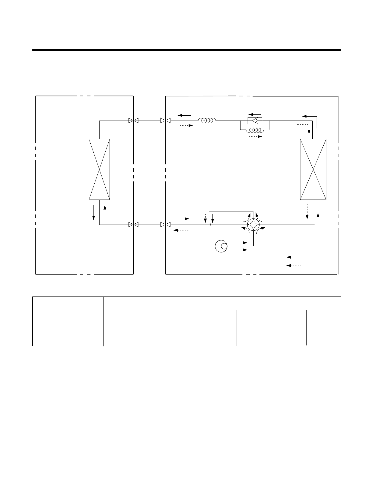
• LV-B1861HL
• LV-B2461HL
For installation over rated distance, 30g of refrigerant should be added for each meter.
ex) When installed at a distance of 15m, 300g of refrigerant should be added.
(15-5) x 30g = 300g
–10–
INDOOR UNIT OUTDOOR UNIT
HEAT
EXCHANGER
HEAT
EXCHANGER
COMPRESSOR
GAS SIDE
LIQUID SIDE
CAPILLARY TUBE
COOLING
HEATING
REVERSING
VALVE
CHECK VALVE
CAPILLARY TUBE
Pipe size(Diameter:) Piping length(m) Elevation(m)
MODEL
Gas Liquid Rated Max Rated Max
LV-B1861HL 1/2" 1/4" 5 15 5 8
LV-B2461HL 5/8" 1/4" 5 20 5 8
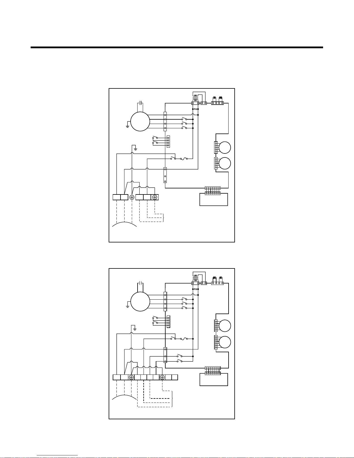
Wiring Diagram
(1) Indoor Unit
–11–
(INDOOR)
DISPLAY PCB
ASSY.
MAIN PCB
ASSY.
TRANSFORMER
THERMISTOR
CN-TH
CN-TRANS
CN-FAN
RY-L
OR
RD
BL
BL
BL
BR
BK
MOTOR
CAPACITOR
BR YL
GN/YL
GN/YL
FUSE
T3.15A
STEP
MOTOR
RY-COMP
CN-4WAY
RY
RD
BK
WH
CN-UP/DOWN 1,2
POWER
INPUT
GN/YL
CN-DISP
DOOR S/W 1,2
3
RY-M
RY-H
TERMINAL
BLOCK
1
(L) 2(N)
3456 78
CONVERTIBLE(HEAT PUMP)
STEP
MOTOR
TO OUTDOOR UNIT
TO OUTDOOR UNIT
(INDOOR)
DISPLAY PCB
ASSY.
MAIN PCB
ASSY.
TRANSFORMER
THERMISTOR
CN-TH
CN-TRANS
CN-FAN
RY-L
OR
RD
BL
BL
BK
MOTOR
CAPACITOR
BR YL
GN/YL
GN/YL
GN/YL
FUSE
T3.15A
STEP
MOTOR
RY-COMP
CN-4WAY
CN-UP/DOWN 1,2
POWER
INPUT
BR
BL
WH
CN-DISP
DOOR S/W 1,2
4
3
RY-M
RY-H
TERMINAL
BLOCK
1
(L) 2(N)
34
CONVERTIBLE(COOLING ONLY)
STEP
MOTOR
1. LV-B1861CL/2461CL
2. LV-B1861HL/2461HL
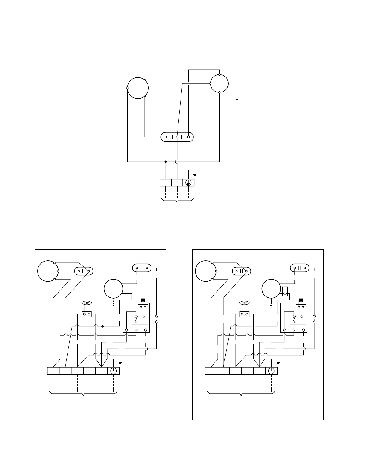
(2) Outdoor Unit
1. LV-B1861CL/2461CL
2. LV-B2461HL
3. LV-B1861HL
–12–
CONVERTIBLE(HEAT PUMP) (OUTDOOR)
CONVERTIBLE(COOLING ONLY) (OUTDOOR)
COMP.
BL
RD
GN/YL
GN/YL
GN/YL
BKBK
L3 L2 L1
CAPACITOR
REVERSING
VALVE
THERMISTOR
CAPACITOR
FAN
MOTOR
R
C
S
TO INDOOR UNIT
34567
TERMINAL
BLOCK
HIGH PRESSURE S/W(FOR HEATING)
BK
BK
BKBK
WH
BR
BL
BK
BK
YL
BR(OR)
YL
CONVERTIBLE(HEAT PUMP) (OUTDOOR)
COMP.
BL
RD
GN/YL
GN/YL
GN/YL
BKBK
L3 L2 L1
CAPACITOR
REVERSING
COIL
THERMISTOR
CAPACITOR
FAN
MOTOR
R
C
S
TO INDOOR UNIT
34567
TERMINAL
BLOCK
HIGH PRESSURE S/W(FOR HEATING)
BK
BK
BKBK
WH
BR
BL
BK
BK
YL
BR(OR)
YL
TO INDOOR UNIT
COMP.
CAPACITOR
FAN
MOTOR
R
S
C
H
F
C
34
TERMINAL
BLOCK
BL
RD
BR
BRBL
BK
T/B
BR(OR)
GN/YL
YL
T/B
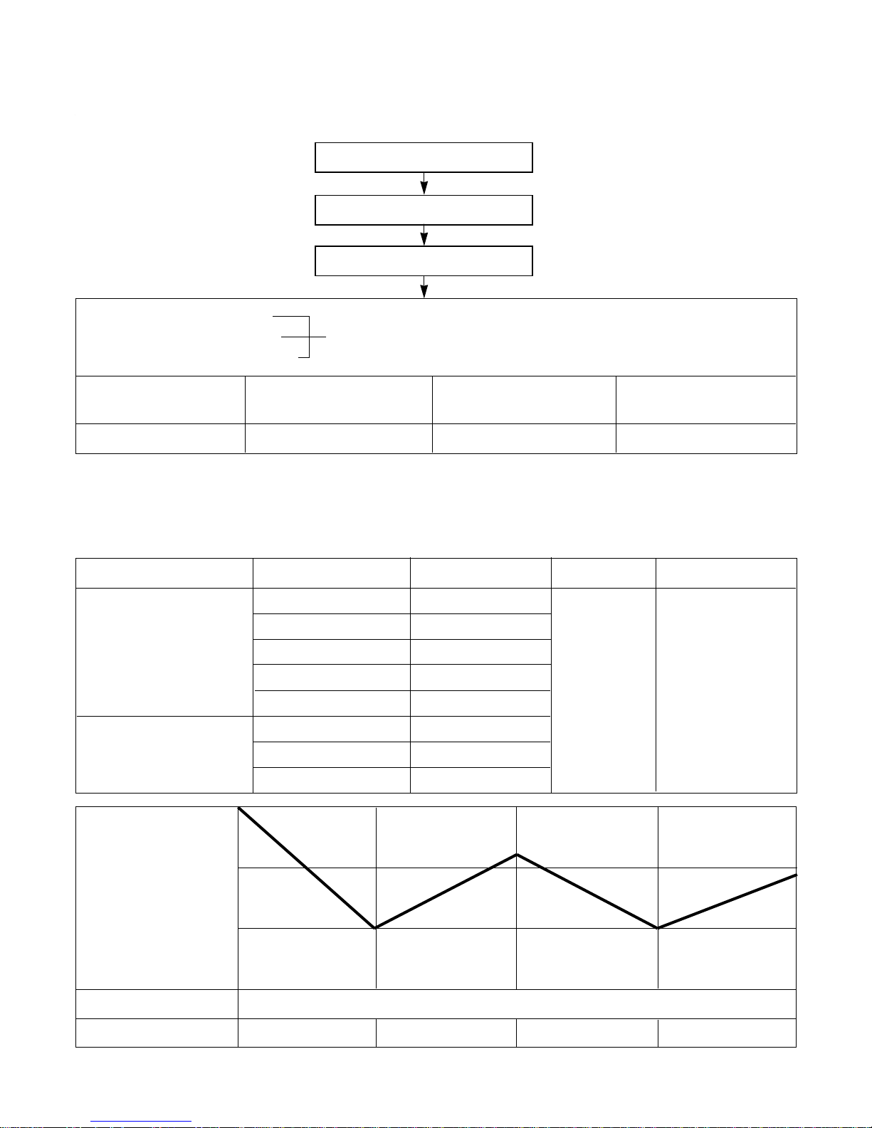
Operation Details
(1) The function of main control
1. Time Delay Safety Control
• 3min…The compressor is ceased for 3minutes to balance the pressure in the refrigeration cycle.
(Protection of compressor)
• 5sec…Vertical air flow direction control louvers open in 5 seconds to prevent noise between louvers and wind.
• 30sec… The 4-way valve is ceased for 30sec. to prevent the refrigerant-gas abnormal noise when the Heating
operation is OFF or switched to the other operation mode while compress is off.
While compressor is running, it takes 3~5 seconds to switch.
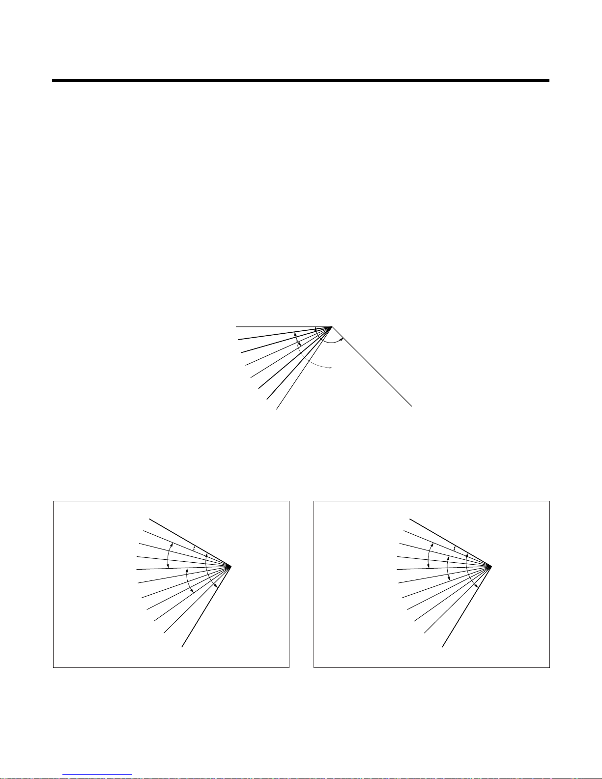
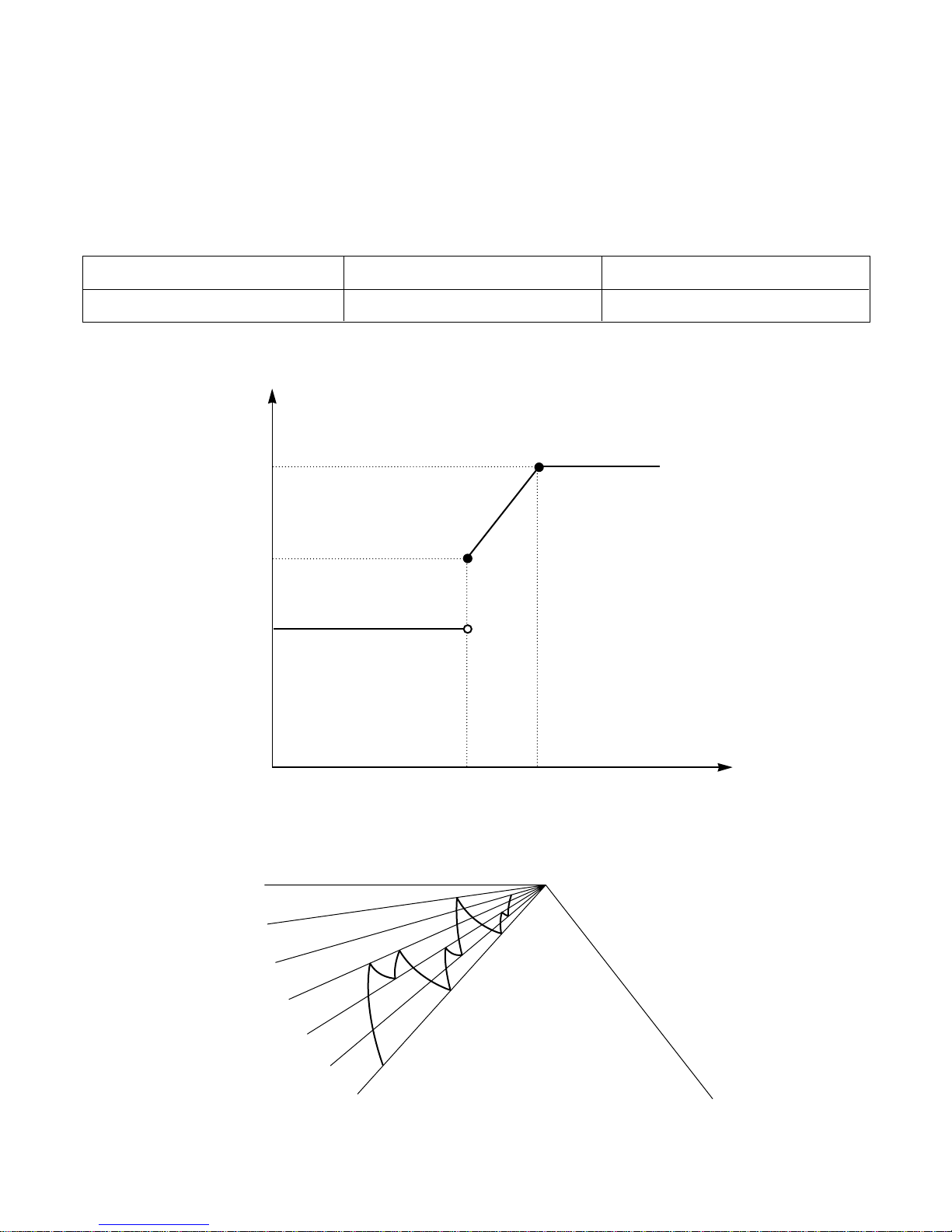
2. Airflow Direction Control
• This function is to swing the louver up and down automatically and to set it at the desired position.
• The procedure is as the following.
1st ; Press the ON/OFF Button to operate the product.
2nd ; Press the Airflow Direction Control Button to swing the louver up and down automatically.
3nd ; Repress the Airflow Direction Control Button to set the louver as the desired position.
MODE 0
1
2
3
4
5
6
7
135°
Cooling
MODE
MODE
MODE
MODE
MODE
MODE
MODE
9
MODE
(CLOSE)
OPEN
135°
12°
Cooling
HeatingHeating
MODE 1
MODE 2
MODE 3
MODE 4
MODE 5
MODE 6
MODE 7
MODE 8
MODE 9
CLOSE
OPEN
135°
12°
Cooling
HeatingHeating
MODE 1
MODE 2
MODE 3
MODE 4
MODE 5
MODE 6
MODE 7
MODE 8
MODE 9
CLOSE
–13–
※ For Heating Model
• Airflow direction control figure when installed on
the floor.
• Airflow direction control figure when installed
under the ceiling.
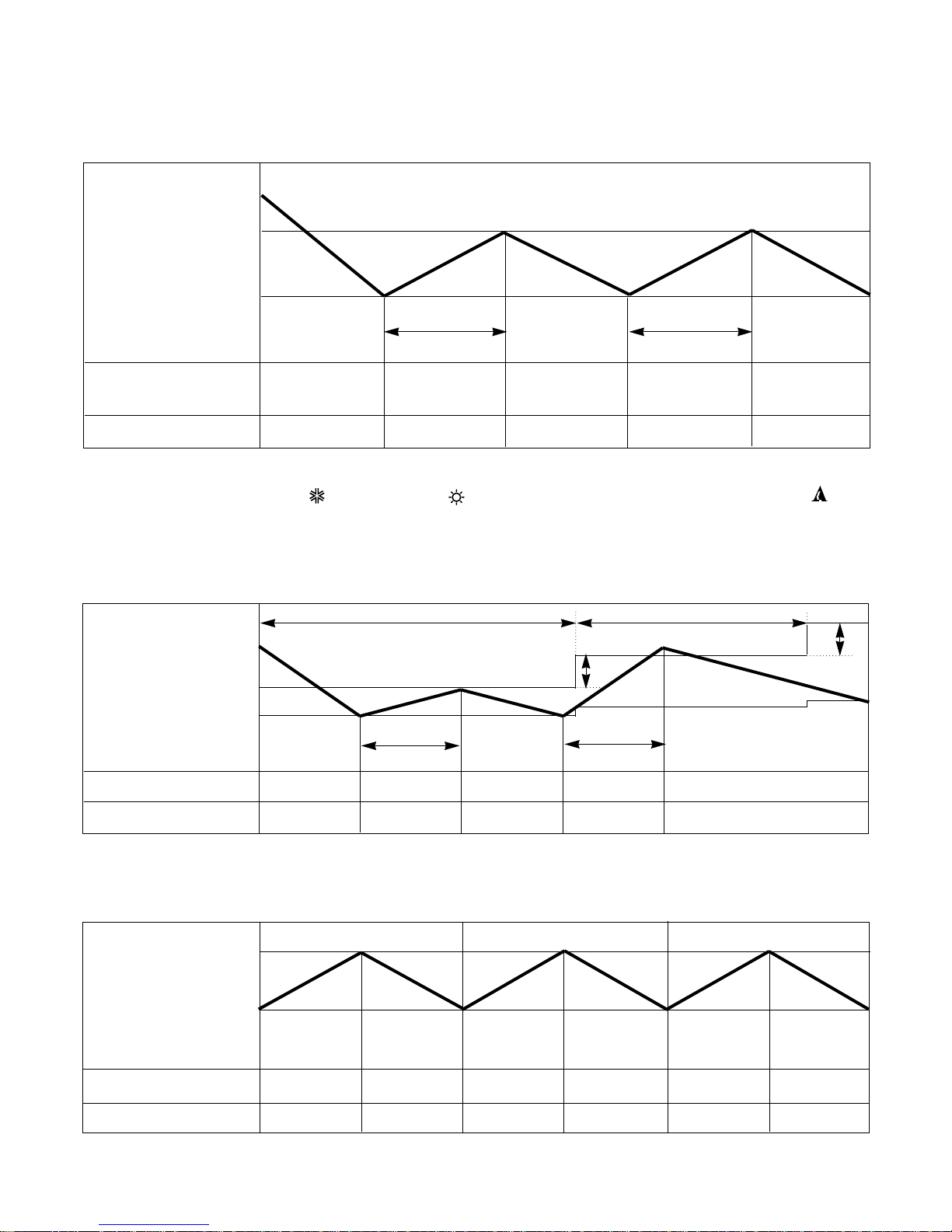
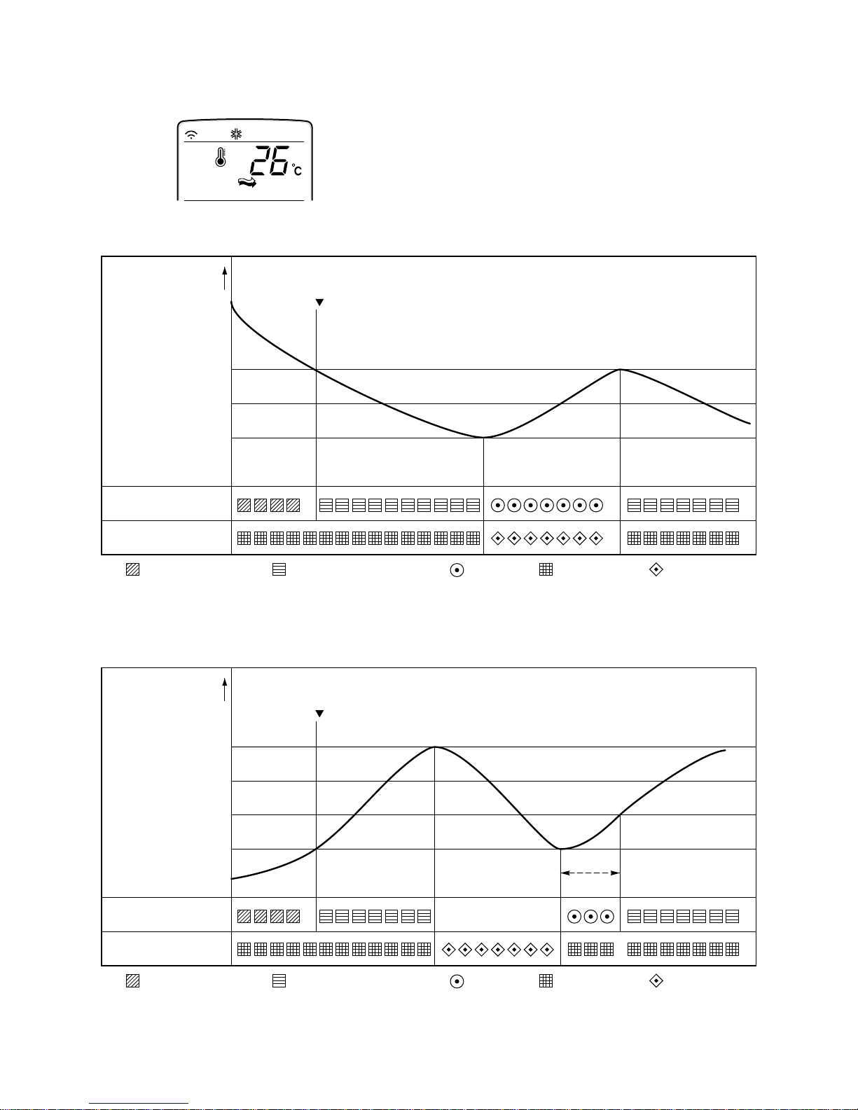
3. Cooling Mode Operation
• When selecting the Cooling( ) Mode Operation, the unit will operate according to the setting by the remote
controller and the operation diagram is as following
4. Cooling or Heating Mode with Sleep Mode Auto Operation
• When selecting the Cooling( ) or the Heating( ) combined with the Sleep Mode Auto Operation( ), the
operation diagram is as following.
■ Cooling Mode with the Sleep Mode
• The setting temperature will be raised by 1°C 30minutes later and by 2°C 1 hour later.
• The operation will be stopped after 1, 2, 3, 4, 5, 6, 7 hours.
■ Heating Mode with the Sleep Mode.
• The operation will be stopped after 1, 2, 3, 4, 5, 6, 7 hours.
Intake Air temp.
COMP. ON
(SET TEMP.+0.5°C)
COMP. OFF
(SET TEMP. -0.5°C) More than More than
3 minutes 3 minutes
INDOOR FAN Low Low Low Low Low
COMPRESSOR ON OFF ON OFF ON
30 minutes 30 minutes
1°C
1°C
–14–
Setting Temp. +3°C
(Compressor OFF)
Setting Temp.
(Compressor ON)
Indoor Fan Med. Med. Med. Med. Med. Med.
Compressor ON OFF ON OFF ON OFF
Intake Air temp.
COMP. ON
(SET TEMP.+0.5°C)
COMP. OFF
(SET TEMP. -0.5°C) More than More than
3 minutes 3 minutes
Selecting Selecting Selecting
fan speed fan speed fan speed
COMPRESSOR ON OFF ON OFF ON
INDOOR FAN Low Low
5. Auto Operation
• The operation procedure is as following. (Cooling & Heating Model)
* If initial mode is decided, that mode is continued without the room temperature changing.
* For cooling operation mode over 24°C setting temperature and fan speed are same as cooling only model.
• Auto Operation for Cooling. (Cooling only Model)
–15–
Press Start/Stop Button
Select Auto Operation Mode
Check the Room temperature
Operation mode
Indoor fan speed are automatically decided by Fuzzy rule.
Setting temperature
Intake-air
temperature
Operation Mode Heating Soft Dry Cooling
Operation Condition Intake-air Temperature Setting temperature Fan speed Air Direction Control
Over 26°C25°C
Over 24°C~below 26°C Intake air -1°C
Over 22°C~below 24°C Intake air -0.5°C
Over 20°C~below 22°C intake air temperture
below 20°C20°C
Over 20°C~below 30°C Fuzzy control
below 20°C20°C
over 30°C30°C
below 21°C
below
24°C
~
Over 24°C
Over
21°C
When Auto Operation
initial start
When pressing room temp-
erature setting button
during Auto Operation
Controlled
by Fuzzy logic
In this mode, when
pressing the vertical air diretion control.
Button, louvers
moves to 1/f
rhythm (refer to
page 17)
Intake-Air temp
Setting Temp. +0.5°C
(Compressor OFF)
Setting Temp.-0.5°C
(Compressor ON)
Indoor Fan
Compressor
ON ONOFF OFF
Fuzzy Speed
• Auto Operation for Soft Dry
The Setting temperature will be same as that of the current intake-air temperature.
- Compressor ON temperature; Setting temperature +1°C
- Compressor OFF temperature; Setting temperature -0.5°C
• Auto Operation for Heating.
- Compressor ON temperature; Setting temperature
- Compressor OFF temperature; Setting temperature +3°C
• 1/f rhythm louver operation : In Auto operation mode, when pressing the vertical air direction control button, lou-
ver moves as following cycle.
–16–
Intake Air temp. below 20°C over 20℃~below 21°C
Setting temp. 20°C Intake air temp. +0.5°C
21.5°C
20°C
20°C
Intake-Air temp.
Setting temp.
20.5°C
21°C
MODE0
MODE1
MODE2
MODE3
MODE4
MODE5
MODE6
MODE9
(CLOSED)
End
Start
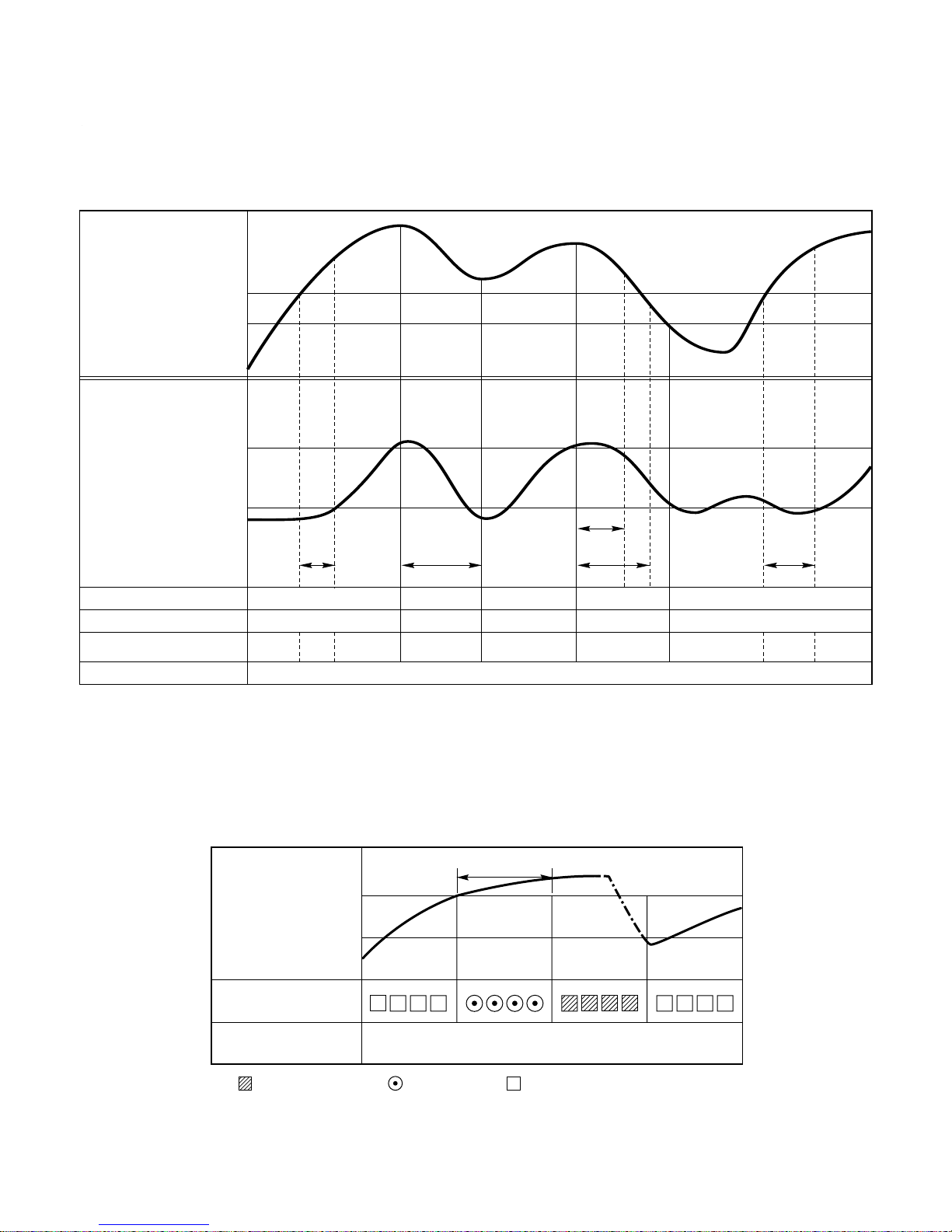
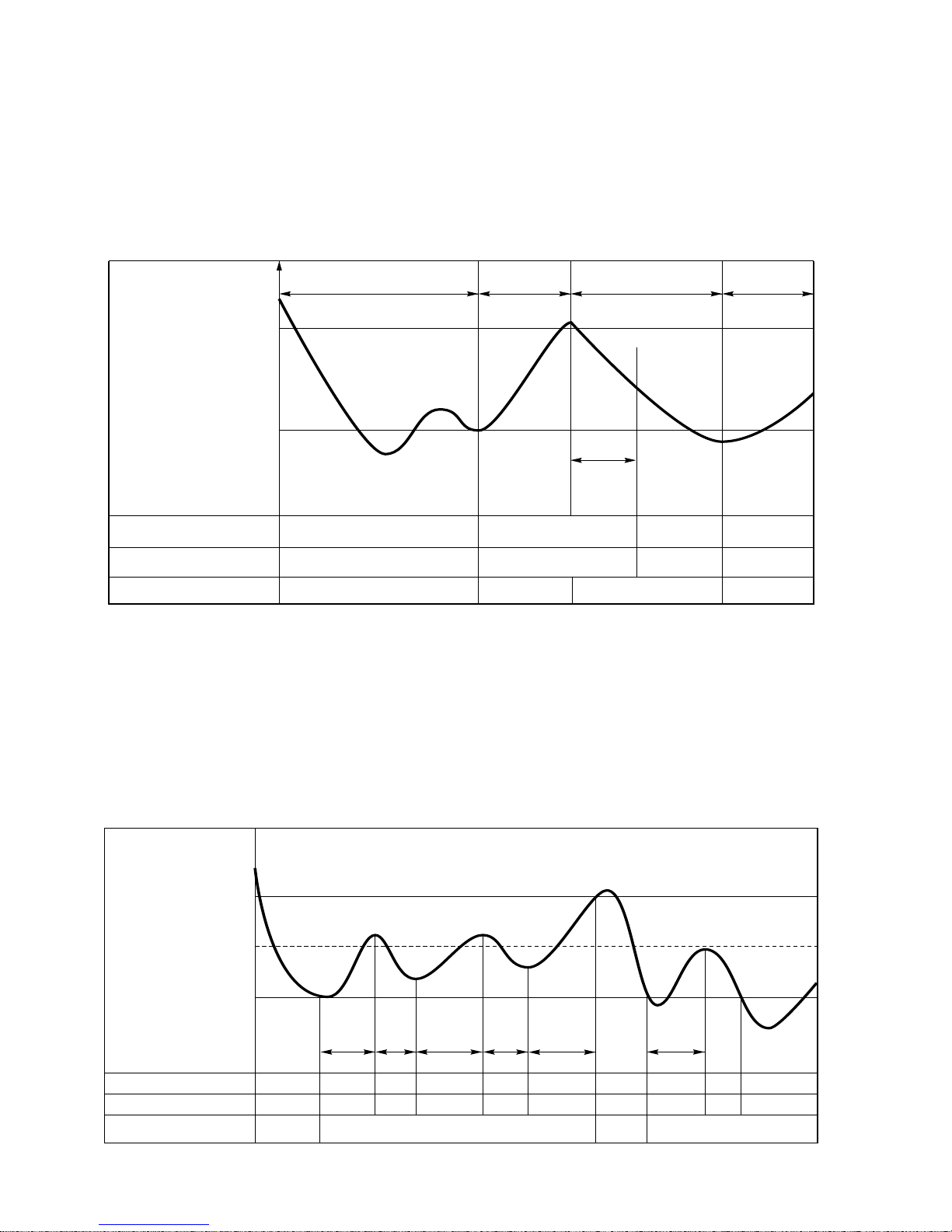
6. Natural wind by CHAOS logic
–17–
For more fresh feeling than other fan speed mode, press
the indoor fan Speed Selector and set to CHAOS mode.
In this mode, the wind blows like natural breeze by automatically changing fan speed according to the CHAOS
logic.
Intake Air temp.
OUTDOOR FAN/COMP.
INDOOR FAN
: Setting fan speed : LOW
Cooling on temp.
(Setting temp.+0.5)
Setting CHAOS Natural wind
Setting temp.
Cooling off temp.
(Setting temp.-0.5)
: CHAOS Natural wind
: COMP ON : COMP OFF
GRAPH of Natural wind by the CHAOS logis (During Cooling operation)
Intake Air temp.
30sec
OUTDOOR FAN/COMP.
INDOOR FAN
: Setting fan speed : LOW
Heating off temp.
(Setting temp.+3.0)
Setting CHAOS Natural wind
Heating on temp.
(Setting temp.)
: CHAOS Natural wind
: COMP ON : COMP OFF
GRAPH of Natural wind by the CHAOS logis (During Heating operation)
LOW OR STOP
–18–
7. Heating Mode Operation
The unit will operate according to the setting by the remote controller and the operation diagram is shown as
following.
• For Heating Model
INDOOR FAN
4-WAY VALVE
ON
ON
ON
OFF
OFF
OFF
OFF
ON
ON
ON
ON
26°C
28°C
Indoor piping temp.
Intake Air temp.
Setting temp. +3.0˚C
(Compressor OFF)
Setting temp.
(Compressor ON)
minimum
1min.
minimum
3min.
Fan
Stops
Low
Fan
Low Fan Low Fan Fan StopSelected Fan
Selected
Fan
Low
Fan
Selected
Fan
minimum
3min.
minimum
30sec.
minimum
1min.
OUTDOOR FAN
COMPRESSOR
8. Hot-Start Control
• The indoor fan stops until the evaporator piping temperature will be reached to 28℃.
• During heating operation, if piping temperatures falls below 26°C fan stops.
• The operation diagram is as following.
PIPING
TEMPERATURE
1min
COMPRESSOR
INDOOR FAN
ON
26°C
: Selected Fan : Low Fan : Fan Stop
28°C
–19–
9. Deice Control ❋ ( ); LV-B2461HL
• Deicing operation is controlled by timer and sensing the outdoor piping temperature.
• The first deicing starts only when the outdoor pipe temperature falls below -6°C after 45(30) minutes passed
from starting of heating operation.
• Deicing ends after 10(6) minutes passed from starting of deice operation or when the outdoor pipe temperature
rises over 12°C even if before 10(6) minutes.
• The second deicing starts only when the outdoor pipe temperture falls below -6°C after 45(30) minutes passed
from ending of the first deicing.
More than 45(30) minutes
of heating operation
Within
10(6) minutes
DeicingDeicing
ON OFF
ON ON
ON
ON OFF OFF
COMPRESSOR
4-WAY VALVE
INDOOR FAN
-6°C
DEICE ON
12°C
DEICE OFF
The outdoor
piping Temp.
ON
More than 45(30) minutes
of heating operation
HOT-
START
ON
OFF
ON
INDOOR FAN
Low Fan Low Fan
Intake Air temp.
Setting temp. +1.0˚C
(Compressor ON)
Setting temp. -0.5˚C
(Compressor OFF)
Setting temp.
2min.58sec. 2min.58sec.
10min. 10min.7min.
Within 7min.
CoolingCooling
OUTDOOR FAN
COMPRESSOR
Selected
Fan
Selected
Fan
ON
ON
ON
ON
OFF
OFF
OFF
OFF
ON
ON
OFF
OFF
ON
ON
OFF
OFFONON
OFF
OFF
10. Soft Dry Operation
• During Soft Dry Operation, the compressor ON temperature is the setting temperature plus 1°C, the compressor
OFF temperature is the setting temperature minus 0.5°C.
• When the room temperature rises over the compressor ON temperature, the operation mode is switched to the
cooling mode.
• When the room temperature falls between the compressor ON temperature and OFF temperature, the operation
mode is switched to the Soft Dry Operation.
In this temperature range, 10min. Dry Operation, 7min operation OFF. During 10min Dry operation, if the room
temperature falls below compressor OFF temperature, Compressor OFF.
• In micom dehumidify mode, control of fan speed is as following.
12. Protection of the evaporator pipe from frosting
If the temperature of the indoor coil is below 0°C after 7 minutes from starting the compressor, the
compressor and the outdoor fan is stopped, and then after 3 minute delay of the compressor and
the temperature of the indoor coil is over 7°C, the compressor and the outdoor fan is reoperated.
Indoor fan operates at low speed (comp. OFF) or at selected speed (comp. ON)
13. Inlet grille open
Once the inlet grille is opened during operation of the unit, the unit automatically stops operation and the
lamps will be turned-off. But memorized functions are still available.
When the inlet grille is closed again, the unit become waiting state for operation. From then, the unit can be
operated by forced operation button or Start/Stop button of remote controller.
14. Test Operation
• When pressing forced operation switch about 3 seconds, the unit operates in cooling mode at high speed fan
regardless of room temperature and resets in 18 min.
• During test operation, if remote controller signal is received, the unit operates as remote controller sets.
15. Auto Restarting Operation
• When the power is restored after a sudden power failure while in appliance operation, the mode before the
power failure is kept on the memory and the appliance should be on the automatically operates in the mode
on the memory.
• Operation Mode that is kept on the memory
- State of Operation ON/OFF
- Operation Mode/Setting Temp/Selected airflow Speed
- Sleep Timer Mode/Remaining Time of Sleep Timer(unit of hour)
• If no input by the remote controller or no switching of the slide switch within 7 hr after the appliance operates
by the Auto Restarting operation, the appliance is forced to stop at the moment of 7-hr elapse.
–20–
11. Forced operation
• If you lose wireless remote controller, you can operate the unit with forced operation switch.
• The standard conditions are as following.
• Unit operates in low fan mode for first 15 seconds, then switched to proper operation mode according to
intake Air temperature.
Heat pump Model
Room Temp≥ 24
°C
21°C〈Room Temp≤24
°C
Room Temp 〈21
°C
Operation Mode Cooling Cooling Soft Dry Heating
FAN Speed High High Soft Dry Rule High
Setting Temp. 24°C22°C Air Intake Temperature 24°C
Cooling Model
R
Forced
Operation Button
Press the Forced Operation Button.
•Press the Forced Operation Button once
again to stop operation.
 Loading...