

OWNER’S MANUAL
DUAL FUEL RANGE
Read this owner’s manual thoroughly before operating the
appliance and keep it handy for reference at all times.
WARNING
If the information in this manual is not followed exactly, a fire or
explosion may result causing property damage, personal injury or
death.
•Do not store or use gasoline or other flammable vapors and liquids in
the vicinity of this or any other appliance.
•WHAT TO DO IF YOU SMELL GAS
- Do not try to light any appliance.
- Do not touch any electrical switch.
- Do not use any phone in your building.
- Immediately call your gas supplier from a neighbor's phone. Follow
the gas supplier's instructions.
- If you cannot reach your gas supplier, call the fire department.
•Installation and service must be performed by a qualified installer,
service agency, or the gas supplier.
LUTD4919SN
MFL68920507
www.lg.com
2
PRODUCT FEATURES
PRODUCT FEATURES
Multiple Gas Burner Sizes
Choose a burner to fit the size of your cookware.
Cooking multiple items at once is possible by using different burners at the
same time.
Self Clean & EasyClean
Useful for easy cleaning.
Wok Grate
Use the included wok grate to safely support a 12" to 14" round-bottomed
wok to stir-fry or saute meats, fish, or vegetables.
®

TABLE OF CONTENTS
3
TABLE OF CONTENTS
PRODUCT FEATURES
2
IMPORTANT SAFETY
4
INSTRUCTIONS
PRODUCT OVERVIEW
12
12 Parts
12 Accessories
INSTALLATION
13
13 Installation Overview
13 Product Specifications
14 Before Installing the Range
16 Installing the Range
19 Optional Rear Filler
20 Providing Adequate Gas Supply
20 Connecting the Range to Gas
21 Connecting Electricity
24 Engaging the Anti-tip Device
24 Test Run
25 Assembling the Surface Burners
25 Checking Ignition of the Surface Burners
OPERATION
26
26 Control Panel Overview
27 Changing Oven Settings
31 Using the Gas Surface Burners
32 Burner Locations
32 Using the Gas Surface Burners
32 Setting the Flame Size
33 In Case of Power Failure
33 Range-Top Cookware
33 Using a Wok
33 Using the Wok Grate
34 Using Stove-Top Grills
34 Using the Griddle
35 Using the Oven
35 Before Using the Oven
35 Oven Vent
35 Using Oven Racks
35 Bake
36 Convection Mode
37 Recommended Baking and Roasting Guide
38 Broil
39 Recommended Broiling Guide
40 Warm
40 Proof
40 Meat Probe
41 Remote Start
SMART FEATURES
42
42 Before Using Smart Features
42 Product Registration
42 Using the Wi-Fi Function
43 Open Source Software Notice Information
43 FCC Notice (For transmitter module contained in
this product)
43 FCC RF Radiation Exposure Statement
MAINTENANCE
44
44 Gas Surface Burners
45 Burner Grates
45 Cleaning the Cooktop Surface
45 Oven Air Vents
45 Control Panel
46 Front Manifold Panel and Knobs
46 EasyClean
49 Self Clean
51 Changing the Oven Light
51 Cleaning the Exterior
53 Removing and Replacing the Lift-Off Oven
Doors
54 Door Care Instructions
TROUBLESHOOTING
55
55 FAQs
57 Before Calling for Service
SMART DIAGNOSIS™
60
60 Using Smart Diagnosis™
60 Smart Diagnosis™ Through the Call Center
WARRANTY
61
®
Rev.00_081616
ENGLISH
4
IMPORTANT SAFETY INSTRUCTIONS
IMPORTANT SAFETY INSTRUCTIONS
Read and follow all instructions when using the range to prevent the risk of fire, electric
shock, personal injury, or damage. This guide does not cover all possible conditions that
may occur. Always contact your service agent or manufacturer about problems that you do
not understand.
Download this owner's manual at: http://www.lg.com
This is the safety alert symbol. This symbol alerts you to potential hazards that
can result in property damage and/or serious bodily harm or death.
All safety messages will follow the safety alert symbol and either the word
WARNING or CAUTION. These words mean:
WARNING
CAUTION
- Indicates a hazardous situation which, if not avoided, could result
in death or serious injury.
Indicates a hazardous situation which, if not avoided, could result
in minor or moderate injury.
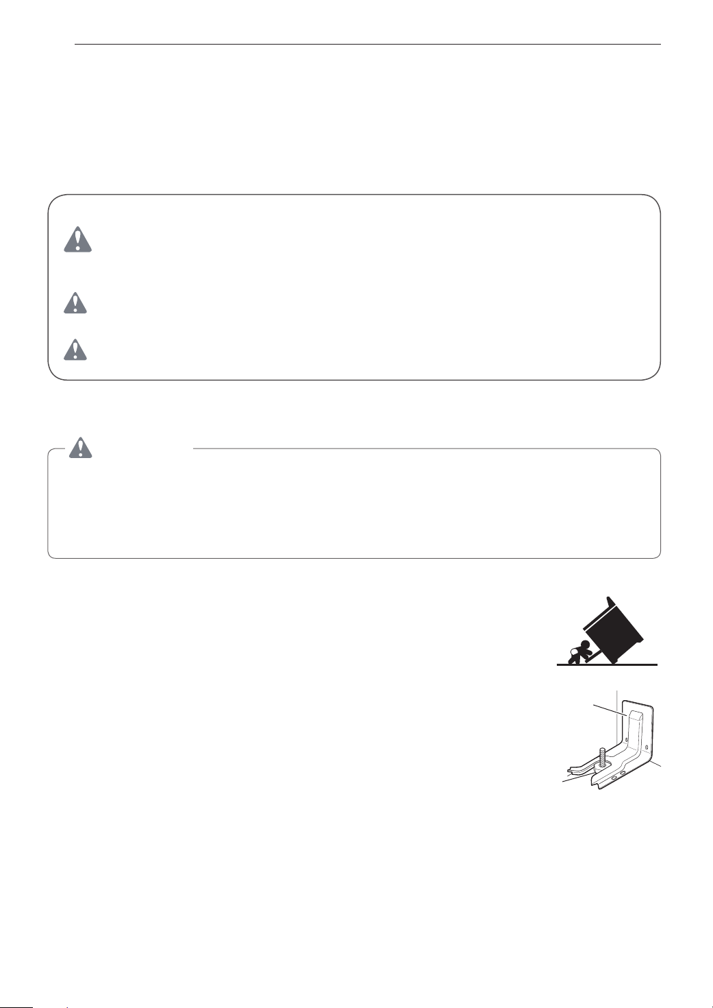
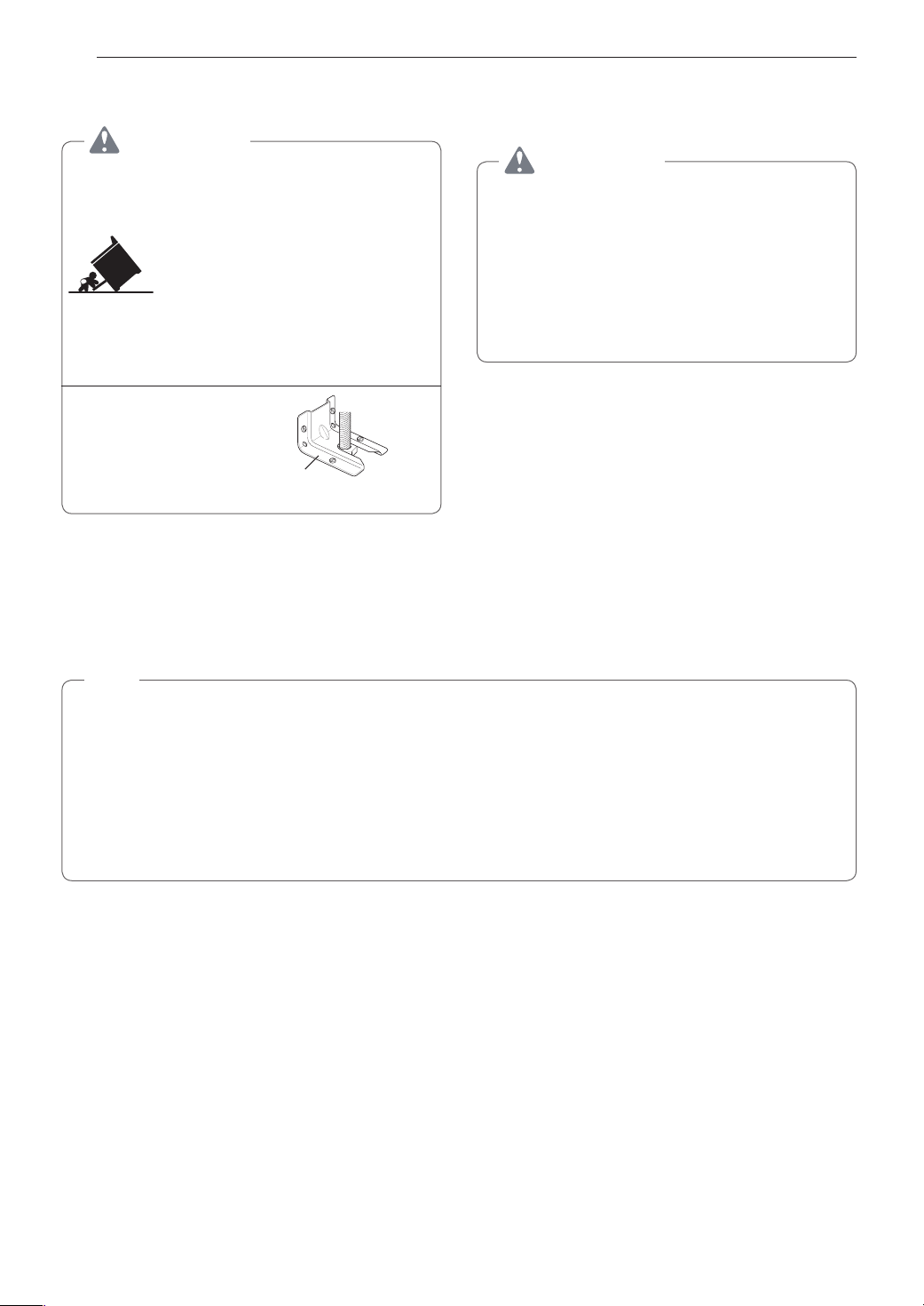
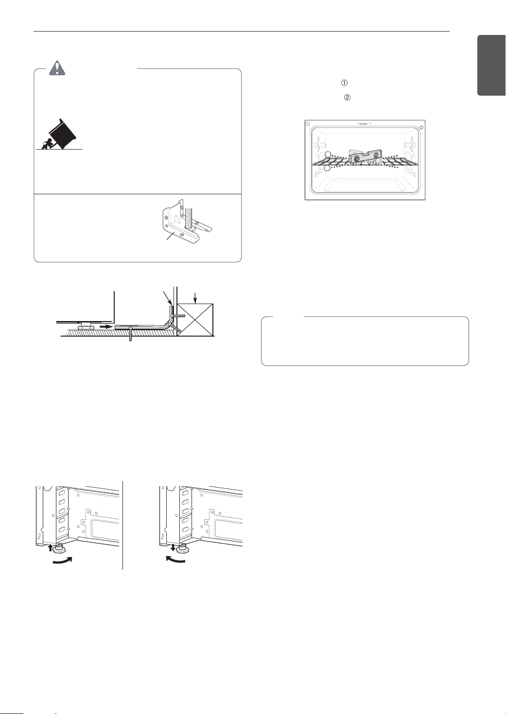
ANTI-TIP DEVICE
WARNING
TO REDUCE THE RISK OF TIPPING, THE APPLIANCE MUST BE SECURED BY A
PROPERLY INSTALLED ANTI-TIP DEVICE. TO CHECK IF THE DEVICE IS INSTALLED
PROPERLY, VERIFY THAT THE ANTI-TIP DEVICE IS ENGAGED, OR GRASP THE
TOP REAR EDGE OF THE RANGE BACK GUARD AND CAREFULLY ATTEMPT TO
TILT IT FORWARD. Refer to the installation section for instructions.
•It is possible for a child or adult to tip the range and be killed.
•Verify that the anti-tip device has been properly installed and
attached to the floor or wall and engaged to the leveling leg of the
range.
•Do not operate the range without the anti-tip device in place and
engaged.
•Never remove the oven legs. The range will not be secured to the
anti-tip bracket if the legs are removed.
•Do not step or sit on the oven door. The range could be tipped and
injury might result from spilled hot liquid, food, or the range itself.
•Do not rest large, heavy items such as whole turkeys on the open
oven door. The range could tip forward and cause injury.
•Reengage the anti-tip device after pulling the range out for
cleaning, service, or any other reason.
•Failure to follow these instructions can result in death or serious burns to children or
adults.
Anti-tip
bracket
Leveling
leg

IMPORTANT SAFETY INSTRUCTIONS
5
INSTALLATION SAFETY PRECAUTIONS
Have the installer show you the location of the range gas shut-off valve and how to shut it
off if necessary.
WARNING
•Make sure the range is properly installed and grounded by a qualified installer,
according to the installation instructions. Any adjustment and service should be
performed only by qualified gas range installers or service technicians.
•Make sure the range is properly adjusted by a qualified service technician or installer
for the type of gas (natural or LP) that is to be used. The range can be converted for
use with either type of gas. See the installation instructions.
•These adjustments must be done by a qualified service technician according to the
manufacturer’s instructions and all codes and requirements of the authority having
jurisdiction. Failure to follow these instructions could result in serious injury or property
damage. The qualified agency performing these adjustments assumes responsibility for
the conversion.
•Disconnect the electrical supply before servicing the appliance.
•Never use the appliance door as a step stool or seat, as this may result in tipping of the
appliance and serious injuries.
•This product should not be installed below ventilation type hood systems that direct air
in a downward direction.
Doing so may cause ignition and combustion problems with the gas burners resulting in
personal injury and may affect the cooking performance of the unit.
•To prevent fire hazard or electrical shock, do not use an adapter plug or an extension
cord, or remove the grounding prong from the electrical power cord. Failure to follow
this warning can cause serious injury, fire or death.
•To prevent poor air circulation, place the range out of the kitchen traffic path and out of
drafty locations.
•Do not attempt to repair or replace any part of the range unless it is specifically
mentioned in this manual. All other services should be referred to a qualified technician.
•Make sure that all packaging materials are removed from the range before operating it
to prevent fire or smoke damage should the packaging material ignite.
•After using the range for an extended period of time high floor temperatures may result.
Many floor coverings will not withstand this kind of use.
•Never install the range over vinyl tile or linoleum that cannot withstand such type of
use. Never install it directly over interior kitchen carpeting.
ENGLISH
6
IMPORTANT SAFETY INSTRUCTIONS
SAFETY PRECAUTIONS
The Safe Drinking Water and Toxic Enforcement Act requires the Governor of California to
publish a list of substances known to the state to cause birth defects or other reproductive
harm, and requires businesses to warn customers of potential exposure to such substances.
Gas appliances can cause minor exposure to four of these substances, namely benzene,
carbon monoxide, formaldehyde and soot, caused primarily by the imperfect combustion
of natural or LP gas. Correctly adjusted burners, indicated by a bluish rather than a yellow
flame, will minimize imperfect combustion. Exposure to these substances can be minimized
by opening windows or using a ventilation fan or hood.
WARNING
This product contains chemicals known to the State of California to cause cancer and
birth defects or other reproductive harm. Wash hands after handling.
•DO NOT TOUCH HEATING ELEMENTS OR INTERIOR SURFACES OF OVEN. Heating
elements may be hot even though they are dark in color. Interior surfaces of an oven
become hot enough to cause burns. During and after use, do not touch or let clothing or
other flammable materials contact heating elements or interior surfaces of oven until they
have had sufficient time to cool. Other surfaces, such as oven vent openings and surfaces
near these openings, oven doors, and windows of oven doors, also get hot and may cause
burns if not cooled.
•Use care when opening door. The hot air and steam that escape can cause burns to
hands, face and eyes. Let hot air or steam escape from the oven before removing or
replacing food in the oven.
•Do not repair or replace any part of the appliance unless specifically recommended in the
manual. All other servicing should be performed by a qualified technician.
•Do not use harsh etching, abrasive cleaners or sharp metal scrapers to clean the oven
door glass since they can scratch the surface. Scratches may cause the glass to shatter.
WARNING
If the door glass, surface, or oven heating unit of the range are damaged, discontinue
use of the range and call for service.
•Do not operate the oven without the charcoal heater mesh.
•Do not use plastic to cover food. Use foil or oven-safe lids only.
•Do not allow anyone to climb, stand or hang on the door or cooktop. They could damage
the range and even tip it over, causing severe personal injury.
•Do not line the oven walls, racks, bottom, or any other part of the oven with aluminum foil
or any other material. Doing so will disrupt heat distribution, produce poor baking results
and cause permanent damage to the oven interior (aluminum foil will melt to the interior
surface of the oven)
•Never attempt to dry a pet in the oven.
•Never use your appliance for warming or heating the room.
•Always use pot holders or oven mitts when removing food from the oven or the surface
element. Cookware will be hot. Use only dry pot holders. Moist or damp pot holders on
hot surfaces may result in burns from steam. Do not let the pot holder touch hot heating
elements. Do not use a towel or other bulky cloth to remove food.
•Do not heat unopened food containers. Pressure in the containers may cause them to
burst which may result in injury.
•Large scratches or impacts to glass doors can lead to broken or shattered glass.
•Leak testing of the appliance must be conducted according to the manufacturer’s
instructions.

IMPORTANT SAFETY INSTRUCTIONS
7
•To eliminate the risk of burns or fire by reaching over heated surface units, cabinet storage
space located above the surface units should be avoided. If cabinet storage is to be
provided, the risk can be reduced by installing a range hood that projects horizontally a
minimum of 5 inches beyond the bottom of the cabinets.
WARNING
•Gas leaks may occur in the system and result in a serious hazard. Gas leaks may
not be detected by smell alone. Gas suppliers recommend you purchase and install
a UL approved gas detector. Install and use in accordance with the gas detector
manufacturer’s instructions.
•To prevent staining or discoloration, clean appliance after each use.
•Do not attempt to open or close the door or operate the oven until the door is properly
installed.
•Never place fingers between the hinge and front oven frame. Hinge arms are spring
mounted. If accidentally hit, the hinge will slam shut against the oven frame and injure
your fingers.
CAUTION
•Wear gloves when cleaning the range to avoid injury or burns.
•Do not use the oven for storing food or cookware.
•To prevent damage to the oven door, do not attempt to open the door when Lock is
displayed.
•Do not stand or place excessive weight on an open door. This could tip the range,
break the door, or injure the user.
•Do not use delayed baking for highly perishable foods such as dairy products, pork,
poultry, or seafood.
ENGLISH
FLAMMABLE MATERIALS
WARNING
Be certain that all packing materials are removed from the appliance before operating.
Keep plastic, clothes, paper, and other flammable materials away from parts of the
appliance that may become hot.
•Do not store or use flammable material in the oven or near or on the cooktop. Flammable
materials include paper, plastic, pot holders, linens, wall coverings, curtains, and gasoline
or other flammable vapors and liquids such as grease or cooking oil. These materials can
be ignited when the oven and cooktop are in use.
•Wear proper apparel. Do not wear loose-fitting or hanging garments, which may ignite if
they contact hot surfaces, and cause severe burns.
•Do not use the oven for drying clothes. Only use the oven for its intended purpose.
•If a cabinet storage is provided directly above cooking surface, place items that are not
frequently used and can be safely stored in an area subjected to heat. Temperatures may
be unsafe for volatile items such as flammable liquids, cleaners or aerosol sprays.
8
IMPORTANT SAFETY INSTRUCTIONS
ELECTRICAL SAFETY
CAUTION
Be certain that all packing materials are removed from the appliance before operating.
Keep plastic, clothes, paper, and other flammable materials away from parts of the
appliance that may become hot.
•Always disconnect power from the appliance before servicing.
•Do not use aluminum foil or any other material to line the oven bottom.
Improper installation of these liners may result in a risk of electric shock or fire.
•Do not allow aluminum foil or the temperature probe to contact heating elements.
WARNING
Before replacing the oven light bulb, switch off the electrical power to the oven at the
main fuse or circuit breaker panel. Failure to do so can result in severe personal injury,
death, or electrical shock.
DEEP FAT FRYER
•Use extreme caution when moving or disposing of hot grease.
•Always heat fat slowly, and watch as it heats.
•If frying combinations of oils and fats, stir them together before heating.
•Use a deep fat thermometer, if possible, to prevent overheating fat beyond the smoking
point.
•Use the least possible amount of fat for effective shallow or deep-fat frying. Filling the pan
with too much fat can cause spillovers when food is added.
CHILD SAFETY
•Do not leave small children unattended near the oven.
WARNING
Do not leave children alone or unsupervised near the appliance when it is in use or is
still hot. Children should never be allowed to sit or stand on any part of the appliance as
they could be injured or burned.
CAUTION
Do not store items of interest to children in cabinets above a range or on the back guard
of a range – children climbing on the range to reach items could be seriously injured.
•Never let a child hang on the oven door.
•Do not allow children to crawl into the oven.
•Let hot utensils cool in a safe place, out of reach of small children.
•Children should not be allowed to play with controls or other parts of the appliance.

IMPORTANT SAFETY INSTRUCTIONS
9
SURFACE BURNERS
WARNING
•Even if the top burner flame goes out, gas is still flowing to the burner until the knob is
turned to the Off position. If you smell gas, immediately open a window and ventilate
the area for five minutes prior to using the burner. Do not leave the burners on
unattended.
•Use proper pan size. Do not use pans that are unstable or that can be easily tipped.
Select cookware with flat bottoms large enough to cover burner grates. To avoid
spillovers, make sure the cookware is large enough to contain the food properly. This
will both save cleaning time and prevent hazardous accumulations of food, since heavy
spattering or spillovers left on the range can ignite. Use pans with handles that can be
easily grasped and remain cool.
CAUTION
•Be sure that all surface controls are set in the Off position prior to supplying gas to the
range.
•Never leave the surface burners unattended at high flame settings. Boilovers may
cause smoke and greasy spillovers that may ignite.
•Always turn the knobs to the Lite position when igniting the top burners and make sure
the burners have ignited.
•Control the top burner flame size so it does not extend beyond the edge of the
cookware. Excessive flame is hazardous.
•Only use dry pot holders- moist or damp pot holders on hot surfaces may result in
burns from steam. Do not let pot holders come near open flames when lifting cookware.
Do not use towels or other bulky cloth items. Use a pot holder.
•If using glass cookware, make sure the cookware is designed for range-top cooking.
•To prevent burns from ignition of flammable materials and spillage, turn cookware
handles toward the side or back of the range without extending them over adjacent
burners.
•Never leave any items on the cooktop. The hot air from the vent may ignite flammable
items and will increase pressure in closed containers, which may cause them to burst.
•Carefully watch foods being fried at a high flame setting.
•Always heat fat slowly, and watch as it heats.
•If frying combinations of oils and fats, stir together before heating.
•Use a deep fat thermometer if possible to prevent fat from heating beyond the smoking
point.
•Use the least possible amount of fat for effective shallow or deep fat frying. Filling the
pan with too much fat can cause spillovers when food is added.
•Do not cook foods directly on an open flame on the cooktop.
•Do not use a wok on the surface burners if the wok has a round metal ring that is
placed over the burner grate to support the wok. This ring acts as a heat trap, which
may damage the burner grate and burner head. It may also cause the burner to work
improperly. This may cause carbon monoxide levels which are higher than what is
allowed by current standards, resulting in a health hazard.
•Foods for frying should be as dry as possible. Frost or moisture on foods can cause hot
fat to bubble up and spill over the sides of the pan.
•Never try to move a pan of hot fat, especially a deep fryer. Wait until the fat is cool.
•Do not place plastic items on the cooktop- they may melt if left too close to the vent.
•Keep all plastics away from the surface burners.
ENGLISH
10
IMPORTANT SAFETY INSTRUCTIONS
CAUTION
•To prevent burns, always be sure that the controls for all burners are in the Off position
and all grates are cool before attempting to remove them.
•If you smell gas, turn off the gas to the range and call a qualified service technician.
Never use an open flame to locate a leak.
•Always turn the knobs to the Off position before removing cookware.
•Do not lift the cooktop. Lifting the cooktop can cause damage and improper operation
of the range.
•If the range is located near a window, do not hang long curtains that could blow over
the surface burners and catch on fire.
•Use care when cleaning the cooktop. The pointed metal ends on the electrodes could
cause injury.
•Stand away from the range while frying.
•Keep an eye on foods being fried at high or medium high heat settings.
ENERGY SAVING TIPS
•Multiple-rack cooking saves time and energy. Whenever possible, cook foods requiring the
same cooking temperature together in one oven.
•For optimal performance and energy savings, follow the guides on page 37 for proper rack
and pan placements.
•Match the size of the cookware to the amount of food being cooked to save energy when
heating. Heating ½ quart of water requires more energy in a 3-quart pot than in a 1-quart
pot.
•Match the size of the cooktop burner or element to the size of the cookware in use. Using
a large element for a small pan wastes heating energy, and the exposed surface of the
element is a burn or fire hazard.
•Reduce energy use by cleaning light oven soils with the EasyClean
self-clean.
•Avoid opening the oven door more than necessary during use. This helps the oven
maintain temperature, prevents unnecessary heat loss, and saves on energy use.
®
feature instead of
SAFETY DURING USE
•Do not touch the oven racks while they are hot.
•If a rack must be moved while the oven is hot, do not let the pot holder contact the hot
heating element in the oven.
•Use caution with the Timed Cook or Delayed Timed Cook features. Use the automatic
timer when cooking cured or frozen meats and most fruits and vegetables. Foods that can
easily spoil, such as milk, eggs, fish, meat or poultry, should be chilled in the refrigerator
first. Even when chilled, they should not stand in the oven for more than 1 hour before
cooking begins, and should be removed promptly when cooking is complete. Eating
spoiled food can result in sickness from food poisoning.
•Accessible parts may become hot when the grill is in use.
•Do not place food or cookware on the bottom of the oven cavity. Doing so will cause
permanent damage to the oven bottom finish.
•Do not use water on grease fires. Should an oven fire occur, leave the oven door closed
and turn the oven off. If the fire continues, throw baking soda on the fire or use a fire
extinguisher. Do not put water or flour on the fire. Flour may be explosive and water can
spread a grease fire and cause personal injury.

IMPORTANT SAFETY INSTRUCTIONS
11
•When disposing of the range, cut off the power cord and remove the door.
•Do not make any attempt to operate the electric ignition oven during an electrical power
failure.
•Pull the oven rack to the stop-lock position when loading and unloading food from the
oven. This helps prevent burns caused by touching hot surfaces of the door and oven
walls.
•Do not use the oven if a heating element develops a glowing spot during use or shows
other signs of damage. A glowing spot indicates the heating element may fail and present
a potential burn, fire, or shock hazard. Turn the oven off immediately and have the heating
element replaced by a qualified service technician.
•When using cooking or roasting bags in the oven, follow the manufacturer’s directions.
SAFETY WHEN CLEANING
•Open a window or turn on a ventilation fan or hood before self-cleaning.
•If the oven is heavily soiled with oil, self-clean the oven before using the oven again. The
oil could cause a fire.
•Wipe up heavy soil on the bottom of the oven before using the Self Clean function.
•Do not use oven cleaners. Commercial oven cleaner or oven liner protective coating of
any kind should not be used in or around any part of the oven.
•Never keep pet birds in the kitchen. The health of birds is extremely sensitive to the fumes
released during an oven self-clean cycle. Fumes may be harmful or fatal to birds. Move
birds to a well-ventilated room.
•Clean in the self-clean cycle only parts listed in this manual. Before self-cleaning the oven,
remove the broiler pan, all oven racks, the meat probe and any utensils or food from the
oven.
•Important Instruction. The oven displays an F error code and sounds three long beeps
during the self-cleaning process if it malfunctions in the self-clean mode. Switch off the
electrical power to the main fuse or breaker and have the oven serviced by a qualified
technician.
•It is normal for the cooktop of the range to become hot during a self-clean cycle. Do not
touch the cooktop during a self-clean cycle.
•Never pour cold water over a hot oven for cleaning. Doing so may cause the oven to
malfunction.
•Make sure oven lights are cool before cleaning.
•Do not clean door gasket. The door gasket is essential for a good seal. Care should be
taken not to rub, damage, or move the gasket.
•If there is a fire in the oven during self-clean, turn the oven off and wait for the fire to go
out. Do not force the door open. Introduction of fresh air at self-clean temperatures may
lead to a burst of flame from the oven. Failure to follow this instruction may result in severe
burns.
•For your safety, do not use high-pressure water cleaners or steam jet cleaners to clean the
product.
ENGLISH
COOK MEAT AND POULTRY THOROUGHLY
•To protect against food-borne illnesses, cook meat and poultry thoroughly. The USDA has
indicated the following as safe minimum internal temperatures for consumption:
•Ground meats: 160 °F
•All poultry: 165 °F
•Beef, veal, pork, or lamb: 145 °F
•Fish/seafood: 145 °F
12
PRODUCT OVERVIEW
PRODUCT OVERVIEW
Parts
Cooktop
Cooktop
controller
Upper
oven door
Lower
oven door
Accessories
Included Accessories
Heavy rack (2ea)
Meat probe (1ea) Griddle (1ea) Rear ller (1ea) Owner’s manual
Gliding rack (1ea) Spray bottle
(1ea)
Non-scratch scouring
pad (1ea)
(1ea)
Oven mode knob
Gasket
Rack
Wok grate (1ea)
Anti-tip kit
Optional Accessories
Anti-tip Screws (6ea) Anchors (6ea) Template
LP nozzle conversion kit
Cooktop nozzles (5ea) Installation guide (1ea) Choke (1ea) Set screw (1ea)
NOTE
•Contact the LG SIGNATURE Customer Information Center at 1-800-984-6306 if any accessories are
missing.
•For your safety and for extended product life, only use authorized components.
•The manufacturer is not responsible for product malfunction or accidents caused by the use of separately
purchased, unauthorized components or parts.
•The images in this guide may be different from the actual components and accessories, which are subject
to change by the manufacturer without prior notice for product improvement purposes.
Grid
Broiler pan
INSTALLATION
13
INSTALLATION
Installation Overview
Please read the following installation instructions first after purchasing this product or transporting it to another
location.
Check and choose the
proper location
Black White Red
Conduit
connection
plate
Install anti-tip device Level the range Connect electric range
Terminal
block
ENGLISH
240 V or 208 V
Pressure regulator
Plug in the power cordConnect the range to gas Engage the anti-tip device Test run
Product Specifications
The appearance and specifications listed in this manual may vary due to constant product improvements.
Oven Range Models LUTD4919SN
Description Dual Fuel Double Oven Range
Electrical requirements 6.9 kW 120/240 VAC or 5.2kW 120/208 VAC
Exterior Dimensions
Height to cooking surface 36" (91.4 cm)
Net weight 196.2 lb (89.0 kg)
29 7/8" (W) x 37 59/64" (H) x 28 15/16" (D) (D with door closed)
75.9 cm (W) x 96.3 cm (H) x 73.5 cm (D) (D with door closed)
Total capacity
Upper Oven: 3.0 cu. ft.
Lower Oven: 4.3 cu. ft.
Total cap.: 7.3 cu. ft.
14
INSTALLATION
Before Installing the Range
If you did not receive an anti-tip bracket with your
purchase, call 1-800-984-6306 to receive one at no
charge.
WARNING
Tip - Over Hazard
A child or adult can tip the range and
be killed. Verify the anti-tip bracket
has been installed. Ensure the
anti-tip bracket is engaged when the
range is moved.
Do not operate the range without the
anti-tip bracket in place. Failure to
follow these instructions can result
in death or serious burns to children
and adults.
To check that leveling leg is
inserted into anti-tip bracket,
grasp the top rear edge
of the range and carefully
attempt to tilt it forward.
Anti-tip
bracket
Leveling
leg
In the Commonwealth of Massachusetts
•This product must be installed by a licensed plumber or gas fitter.
•When using ball type gas shut-off valves, they must be the T-handle type.
•When using a flexible gas connector, it must not exceed 3 feet in length.
WARNING
•The information in this manual should be
followed exactly. Failure to do so may result
in fire, electrical shock, property damage,
personal injury, or death.
•Wear gloves during the installation
procedure. Failure to do so can result in bodily
injury.
•Make sure no parts came loose during shipping.
NOTE
•Observe all governing codes and ordinances.
•Have the installer show you the location of the circuit breaker or fuse. Mark it for easy reference.
•As when using any appliance generating heat, there are certain safety precautions you should follow.
•Be sure your range is installed and grounded properly by a qualified installer or service technician
according to the installation instructions.
•Any adjustment and service should be performed only by qualified gas range installers or service
technicians.
INSTALLATION
15
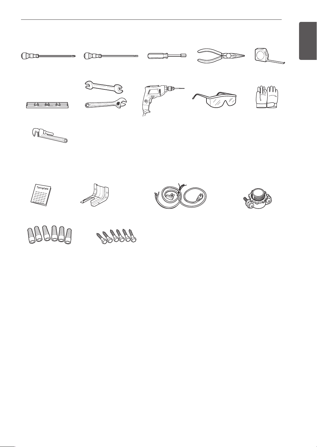
Preparing for Installation
Tools Needed
Phillips screwdriver
Level
Pipe wrench (2)
(one for support)
Parts Provided
Flat-blade screwdriver
Open-end or
adjustable wrench
1
/4" Nut driver
Drill
Parts not Provided
Pliers
Safety glasses
ENGLISH
Tape measure
Gloves
Template (1)
Anchor sleeves (6) Lag bolts (6)
Anti-tip bracket kit (1)
4-Wire cord or
3-Wire cord
(UL approved 40 or 50
AMP)
Materials You May Need
•Gas line shut-off valve
•Pipe joint sealant that resists action of natural and LP gases
•Flexible metal appliance connector (
3
/4" or 1/2" NPT x 1/2" I.D.)
Never use an old connector when installing a new range.
•Flare union adapter for connection to gas supply line (
3
/4" or 1/2" NPT x 1/2" I.D.)
•Flare union adapter for connection to pressure regulator on range (
•Liquid leak detector or soapy water
•Lag bolt or
1
/2" O.D. sleeve anchor (for concrete floors only)
1
/2" NPT x 1/2" I.D.)
Strain relief
(For conduit
Installations only)
16
INSTALLATION
Installing the Range
Unpacking and Moving the Range
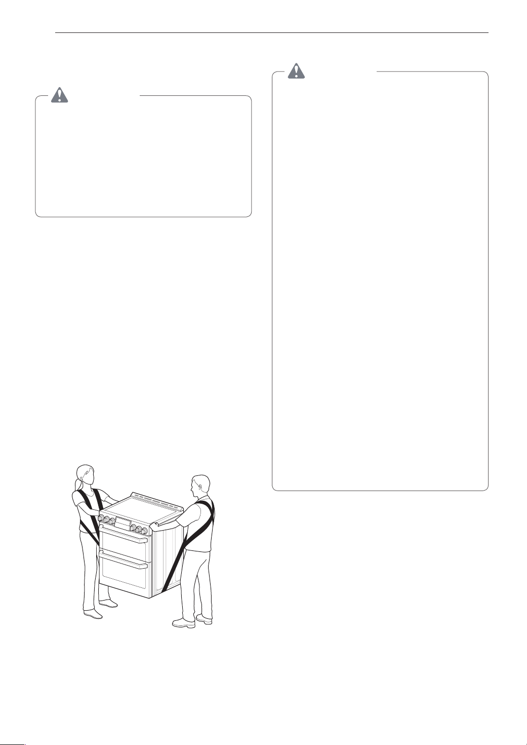
CAUTION
•You should use two or more people to move
and install the range. (Excessive Weight
Hazard) Failure to do so can result in back or
other injury.
•Do not use the door handles to push or
pull the range during installation or when
moving the range out for cleaning or
service. Doing so can result in serious damage
to the door of the range.
Remove packing material, tape and any temporary
labels from your range before using. Do not remove
any warning-type labels, the model and serial number
label, or the Tech Sheet that is located on the back of
the range.
To remove any remaining tape or glue, rub the area
briskly with your thumb. Tape or glue residue can also
be easily removed by rubbing a small amount of liquid
dish soap over the adhesive with your fingers. Wipe
with warm water and dry.
Do not use sharp instruments, rubbing alcohol,
flammable fluids, or abrasive cleaners to remove tape
or glue. These products can damage the surface of
your range.
The range is heavy and can be installed on soft
floor coverings such as cushioned vinyl or carpeting.
Use care when moving the range on this type of
flooring. Use a belt when moving the range to prevent
damaging the floor. Or slide the range onto cardboard
or plywood to avoid damaging the floor covering.
Choosing the Proper Location
CAUTION
•Avoid placing cabinets above the range. To
minimize the hazard caused by reaching over
the open flames of operating burners, install a
ventilation hood over the range that projects
forward at least five inches beyond the front of
the cabinets.
•Do not locate your range where it may be
subject to strong drafts. Any openings in the
floor or wall behind the range should be sealed.
Make sure the openings around the base of
the range that supply fresh air for combustion
and ventilation are not blocked by carpeting or
woodwork.
•This range is for indoor, household use
only. Do not install the range in areas exposed
to the weather and/or water.
•If the range is located near a window, do not
hang long curtains or paper blinds on that
window.
•Make sure wall covering, countertop and
cabinets around the range can withstand
the heat (up to 194 °F) generated by the
range. Discoloration, delamination or melting
may occur. This range has been designed to
comply with the maximum allowable wood
cabinet temperature of 194 °F.
•Before installing the range in an area
covered with linoleum or other synthetic
floor covering, make sure the floor covering
can withstand temperatures of at least
160 °F(70°C).
•Use an insulated pad or
plywood under the range if installing the
range over carpeting.
1
/4 in. (0.64 cm)
The range should always be plugged into its own
individual properly grounded electrical outlet. This
prevents overloading house wiring circuits which
could cause a fire hazard from overheated wires. It is
recommended that a separate circuit serving only this
appliance be provided.
This appliance must not be installed with a ventilation
system that blows air downward toward the range.
This type of ventilation system may cause ignition and
combustion problems with the gas cooking appliance
resulting in personal injury or unintended operation.
When the floor covering ends at the front of the
range, the area that the range will be installed on
should be built up with plywood to the same level
or higher than the floor covering. This will allow the
range to be moved for cleaning and servicing, as well
as provide proper air flow to the range.

INSTALLATION
17
Mobile Home - Additional Installation
Requirements
The installation of this range must conform to the
Manufactured Home Construction and Safety
Standard, Title 24 CFR, Part 3280 (formerly the
Federal Standard for Mobile Home Construction
and Safety, Title 24, HUD Part 280), or when
such standard is not applicable, the Standard for
Manufactured Home Installations, ANSI A225.1/NFPA
501A or with local codes.
•When this range is installed in a mobile home, it
must be secured to the floor during transit. Any
method of securing the range is adequate as long
as it conforms to the standards listed above.
•A four-wire power supply cord or cable must be
used in a mobile home installation.
ENGLISH
18
INSTALLATION
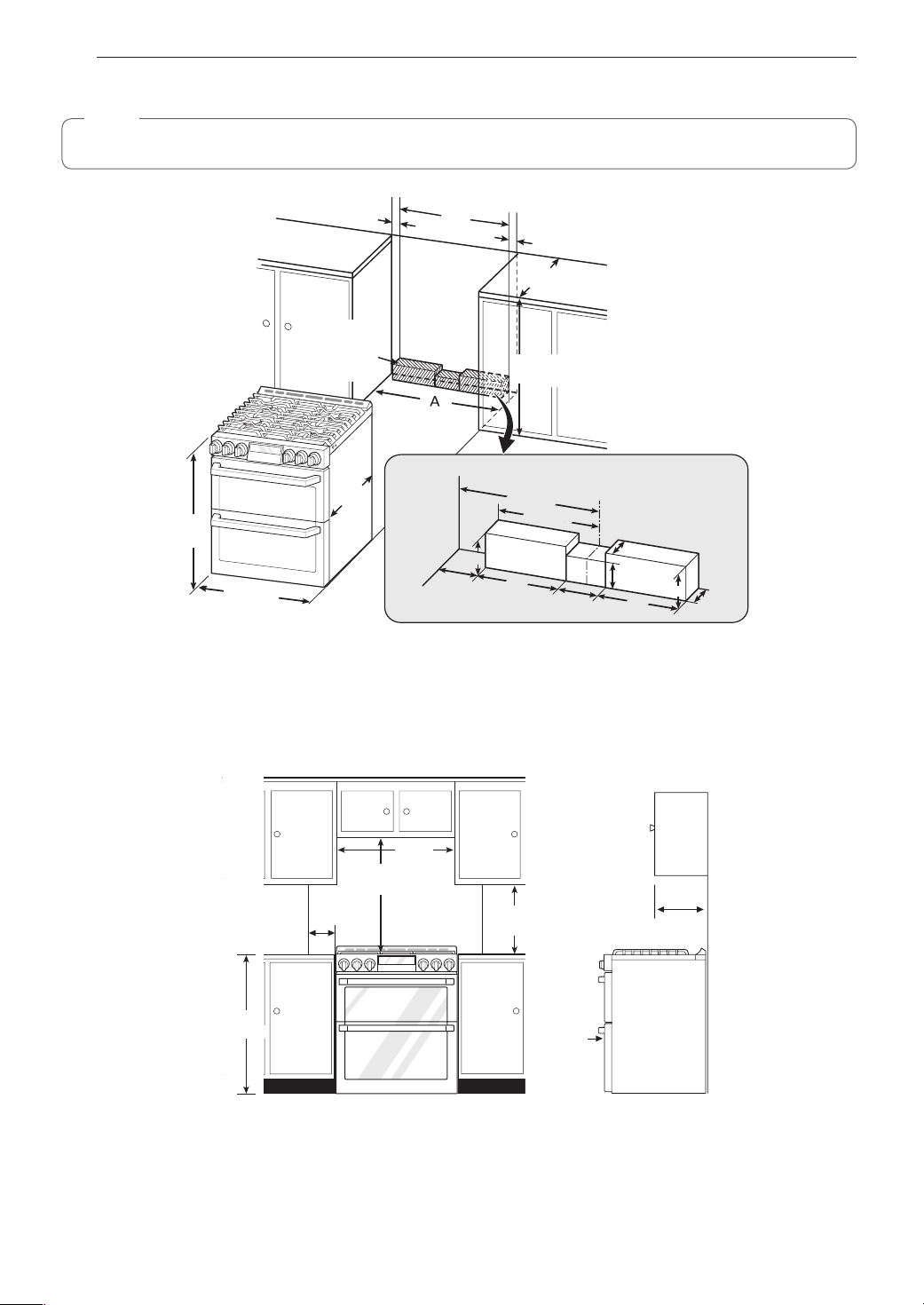
Dimensions and Clearances
NOTE
Save for the use of the local electrical inspector.
3" (7.6 cm)
24"
(60.9 cm)
3" (7.6 cm)
25"
(63.5 cm)
Normal counter
top depth
Acceptable
gas pipe and
electrical
outlet area
36"
(91.4 cm)
Counter
top height
Cabinet
opening
Wall
36"
(91.4 cm)
29.8"
(75.7 cm)
24"
(60.9 cm)
Cabinet
(10 cm)
15" (38 cm)
6"
(15.2 cm)
4"
9"
(23 cm)
11" (28 cm)
(10 cm)
Center
4"
5"
(13 cm)
(23 cm)
A = 30" (76.2 cm) For U.S.A
= 30" (76.2 cm) ~ 31" (78.7 cm) For CANADA
For installation in Canada, a free-standing range is not to be installed closer than
adjacent surface.
2.5" (6.3 cm)
6"
(15.2 cm)
9"
15
/32" (12 mm) from any
2.5"
(6.3 cm)
Maximum
depth for
cabinets above
countertops
1
/4"
(0.64 cm)
13"
(33.0 cm)
Front edge of
the range side
panel forward
from cabinet
36"
(91.4 cm)
*30" (76.2 cm)
Minimum
5"(12.7 cm)
Minimum
30"
(76.2 cm)
**15"
(38.1 cm)
Minimum Dimensions
* 30" (76.2 cm) minimum clearance between the top of the cooking surface and the bottom of an unprotected
wood or metal cabinet; or 24" (60.9 cm) minimum when bottom of wood or metal cabinet is protected by not less
1
/4" (0.64 cm) flame retardant millboard covered with not less than no. 28 MSG sheet steel, 0.015"
than
mm)
stainless steel, 0.024" (0.610 mm) aluminum or 0.020" (0.508 mm) copper.
(0.381
** 15" (38.1 cm) minimum between countertop and adjacent cabinet bottom.
INSTALLATION
19
Installing the Anti-tip Device
WARNING
Tip - Over Hazard
A child or adult can tip the range and
be killed. Verify the anti-tip bracket
has been installed. Ensure the anti-tip
bracket is engaged when the range
is moved. Do not operate the range
without the anti-tip bracket in place.
Failure to follow these instructions
can result in death or serious burns to
children and adults.
To check that leveling leg is
inserted into anti-tip bracket,
grasp the top rear edge
of the range and carefully
attempt to tilt it forward.
Screw must
enter wood or
concrete
Locate the anti-tip bracket using the template
An anti-tip bracket is packaged with the template.
The instructions include necessary information to
complete the installation. Read and follow the range
installation instruction sheet (template).
Anti-tip
bracket
Anti-tip
bracket
Leveling the Range
Level the range by adjusting the leveling legs with a
wrench. Extending the legs slightly may also make it
easier to insert the rear leg into the anti-tip bracket.
Leveling
leg
Wall plate
Use a level to check your adjustments. Place the level
diagonally on the oven rack, and check each direction
for level.
First check direction
Then check direction
on the rack, adjust the leveling legs with a wrench.
.
. If the level doesn’t show level
2
1
Optional Rear Filler
If the counter does not bridge the opening at the rear
wall, use the rear filler kit provided with the slide-in
range.
NOTE
If the countertop depth is greater than 26" there
will be a gap between the filler kit and the back
wall.
If the countertop depth is less than 25", the control
panel will not sit flush with the countertop.
Installing the Rear Filler
Using a screwdriver, remove the upper four
1
screws that attach the rear bracket and loosen
the lower two screws.
Place the rear filler on the rear bracket.
2
ENGLISH
Tighten the two lower screws on the rear
3
bracket. Insert one of the screws removed in
step 1 in the slot at each end of the rear filler.
Store the remaining two screws with these
4
instructions for future use.
20
INSTALLATION
Providing Adequate Gas
Supply
The range is designed to operate at a pressure of
5" of water column on natural gas or 10" of water
column on LP.
Make sure you are supplying the range with the type
of gas for which it is configured.
This range is convertible for use on natural or LP gas.
When using this range on LP gas, conversion must
be made by a qualified LP installer before attempting
to operate the range.
For proper operation, the pressure of natural gas
supplied to the regulator must be between 5" and 13"
of water column.
For LP gas, the pressure supplied to the regulator
must be between 10" and 13" of water column. When
checking for correct operation of the regulator, the
inlet pressure must be at least 1" more than the
operating (manifold) pressure as given above.
The pressure regulator located at the inlet of the
range must remain in the supply line regardless of
which type of gas is being used.
A flexible metal appliance connector used to connect
the range to the gas supply line should have an I.D.
5
of
/8" and a maximum length of 5 feet. In Canada,
flexible connectors must be single wall metal
connectors less than 6 feet in length.
Connecting the Range to Gas
Shut off the range gas supply valve before removing
the old range and leave it off until the new hook-up
has been completed.
Because hard piping restricts movement of the range,
a CSA International-certified flexible metal appliance
connector should be used unless local codes require
a hard-piped connection.
A manual valve shall be installed in an accessible
location in the gas piping external to the appliance
for the purpose of turning on or shutting off gas to the
appliance.
Never reuse an old connector when installing a new
range.
To protect against gas leaks, use a qualified pipe joint
sealant on all external threads.
Install a male 1/2" or 3/4" flare union adapter to the
1
NPT internal thread of the manual shut-off valve,
taking care to back-up the shut-off valve to keep
it from turning.
Install a male 1/2" flare union adapter to the 1/2"
2
NPT internal thread at the inlet of the pressure
regulator. Use a backup wrench on the pressure
regulator fitting to prevent damage.
Connect a flexible metal appliance connector to
3
the adapter on the range. Position the range to
permit connection at the shut-off valve.
When all connections have been made, be sure
4
all range controls are in the Off position and turn
on the main gas supply valve. Gas leaks may
occur in your system and create a hazard. Gas
leaks may not be detected by smell alone.
Check all gas connection joints and fittings for
leaks with a non-corrosive leak detection fluid,
then wipe off.
Gas suppliers recommend you purchase and
install a UL approved gas detector. Install
and use in accordance with the installation
instructions.
WARNING
•Do not use a flame to check for gas leaks.
•Isolate the range from the gas supply system
by closing its individual shut-off valve during
any pressure testing of the gas supply system
at test pressures equal to or less than
(3.5 kPa).
1
/2" psig
INSTALLATION
21
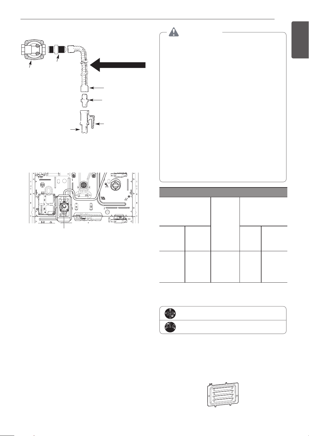
Flexible Connector Hookup
1
Adapter
/2"
Pressure regulator
1
/2" or 3/4" Gas
Installer: Inform the consumer of the location of the gas
shutoff valve
pipe
.
Gas Flow into Range
Flex connector
(6 ft. max.)
Adapter
Gas shut-off
valve
Pressure Regulator Position
Pressure Regulator
Connecting Electricity
Electrical Requirements
This appliance must be installed and grounded on a
branch circuit by a qualified technician in accordance
with the National Electrical code ANSI/NFPA NO. 70 latest edition.
All wiring should conform to Local and NEC codes.
This range requires a single-phase, 3 wire, A.C
120/208 V or 120/240 V 60 Hz electrical system. Use
only a 3-conductor or a 4-conductor UL- listed range
cord with closed-loop terminals, open-end spade
lugs with upturned ends or similar termination. Do not
install the power cord without a strain relief.
A range cord rated at 40 amps with 120/208 or
120/240 minimum volt range is required. If a 50 amp
range cord is used, it should be marked for use with
3
1
/8" diameter connection openings. This appliance
may be connected by means of a conduit or power
cord. If a conduit is being used, go to page 23 for
3 wire conduit connections or 4 wire conduit
connections.
WARNING
•Allow 2 to 3 ft (61.0 cm to 91.4 cm) of slack
in the line so that the range can be moved if
servicing is ever necessary.
•The power supply cord and plug should
not be modified. If it will not fit the outlet,
have a proper outlet Installed by a qualified
electrician.
•Using an extension cord to connect the
power is prohibited. Connect the power cord
and plug directly.
•Electrical ground is required on this appliance.
•Make sure that the power cord is not pinched
by the range or heavy objects. Failure to do so
can result in serious burns or electrical shock.
•Do not use a damaged power plug, power
cord, or loose power outlet.
•Do not put a fuse in a neutral or ground circuit.
•Do not connect the ground wire to plastic
plumbing lines, gas lines, or hot water pipes.
Specified power-supply-cord kit rating
Diameter (inches)
Range rating, watts
Specified
rating of
power
120/240
volts
3-wire
8,750 16,500
16,501 22,500
120/208
volts
3-wire
7,801 12,500
12,501 18,500
supply-
cord kit,
amperes
40 or 50A
50
3, 4 - Wire electrical wall Receptacle
4 Wire receptacle (14-50R)
3 Wire receptacle (10-50R)
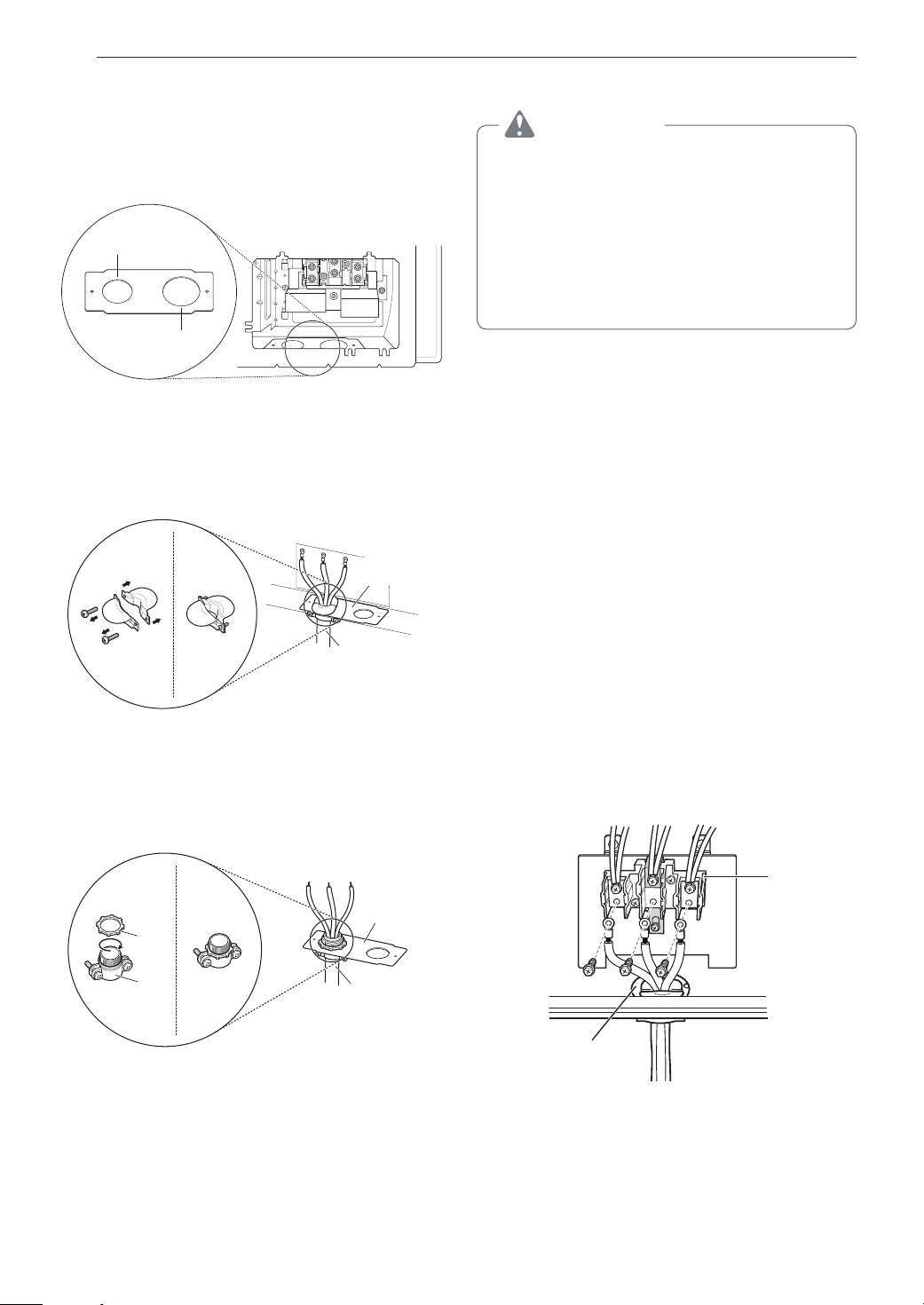
Connecting the Power Cord
The rear access cover must be removed. Loosen the
two screws with a screwdriver. The terminal block will
then be accessible.
Access cover
of Range
connection
Opening
Power
cord
3
/8"
1
1 3/4"
Conduit
1
/8"
1
1 3/8"
ENGLISH
22
INSTALLATION
Use the cord/conduit connection plate to install the
power cord or conduit. Leave the connection plate
as installed for power cord installations. Remove the
connection plate for conduit installations and use the
smaller 11/8 in. (2.8 cm) conduit hole instead of the
13/8 in. (3.5 cm) power cord hole.
1
/8"
(2.8 cm) Conduit
1
13/8"
(3.5 cm) Cord
Remove the Conduit connection plate
For power cord installations, hook the strain relief
over the 1
3
/8 in. (3.5 cm) power cord hole located
below the rear of the oven. Insert the power cord
through the strain relief and tighten it.
Conduit
connection
plate
Power cord
3-Wire Connection : Power Cord
WARNING
•The middle (neutral or ground) wire, which
is white, of a 3-wire power cord or a 3-wire
conduit has to be connected to the middle
post of the main terminal block. The
remaining two wires of the power cord or
conduit have to be connected to the outside
posts of the main terminal connection block.
Failure to do so can result in electrical shock,
severe personal injury or death.
Install the power cord as follows:
For power cord installations, hook the strain relief
over the power cord hole (1
rear of the oven. Insert the power cord through the
strain relief and tighten it.
Do not install the power cord without a strain
relief.
Remove the lower 3 screws from the terminal
1
block and retain them.
Insert the 3 screws through each power cord
2
terminal ring and into the lower terminals of
the terminal block. Make sure that the center
(neutral) wire, which is white, is connected to the
center lower position of the terminal block.
3
/8") located below the
3
Assembling power cord strain relief at the 1
/8" opening
For conduit installations, insert the conduit strain
relief in the 11/8 in. (2.8 cm) conduit hole. Then install
the conduit through the body of the strain relief and
fasten the strain relief with its ring.
Cord/
Conduit
connection
plate
Ring
Body
Assembling conduit cord strain relief at the 1
Conduit
1
/8" opening
Tighten the 3 screws securely into the terminal
3
block. Do not remove the ground strap
connections.
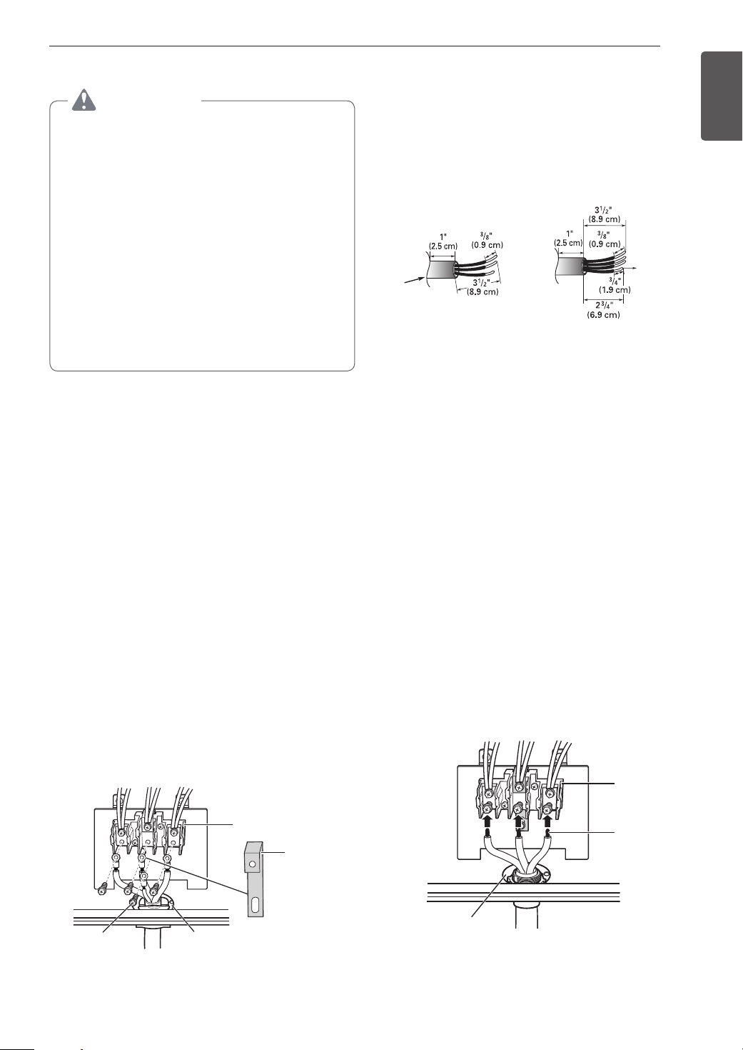
3-wire connection
Black White Red
Terminal
block
Conduit
connection plate
If screws are not tightened securely, it can result in
electrical spark and severe personal injury or death.
INSTALLATION
23
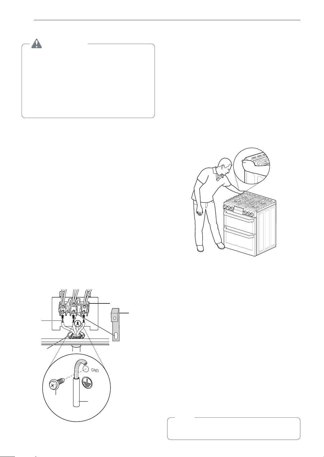
4-Wire Connection : Power Cord
WARNING
•Only a 4-conductor power-supply cord kit
rated 120/208 or 120/240 volts, 50 amperes
and marked for use with ranges with closedloop connectors or opened spade lugs with
upturned ends shall be used.
The white middle (neutral) wire of the power
cord or 4-wire conduit has to be connected
to the middle post of the main terminal
block. The other two wires of the power
cord or conduit have to be connected to
the outside posts of the main terminal
connection block. The 4th ground wire
(green) must be connected to the frame of
the range with the ground screw. Failure
to do so can result in electrical shock, severe
personal injury or death.
Install the power cord as follows:
Do not install the power cord without a strain
relief.
Remove the lower 3 screws from the terminal
1
block and retain them.
Remove the ground screw and bend the end of
2
the ground strap up so the slot is over the hole
of the center screw removed in step 1.
Insert the ground screw into the power cord
3
ground wire (green) terminal ring and secure it to
the range frame.
Insert the 3 screws through each power cord
4
terminal ring and into the lower terminals of the
terminal block. Make sure that the white center
(neutral) wire is connected to the center lower
position of the terminal block.
Tighten the 3 screws securely into the terminal
5
block. The center screw now attaches the bent
up ground strap to the block.
3-Wire Connection: Conduit
Install the conduit as follows:
Remove the conduit connection plate from the rear of
the oven and rotate it. The conduit hole (1
be used.
First, prepare the conduit wires as shown below.
3-Wire
Conduit
connection
plate
Second, install the conduit strain relief.
For conduit installations, purchase a strain relief and
insert it in the 1
install the conduit through the body of the strain relief
and fasten the strain relief with its ring. Reinstall the
bracket.
For conduit connections:
If the wire in the conduit is copper it must be 8 or 10
AWG wiring.
If the wire in the conduit is aluminum it must be 6 or 8
AWG wiring.
Loosen the lower 3 screws from the terminal
1
block.
Insert the bare wire (white/neutral) end through
2
the center terminal block opening. Do not
remove the ground strap connections.
Insert the two side bare wire ends into the lower
3
left and the lower right terminal block openings.
Tighten the 3 screws securely into the terminal
block. (approximately 35 - 50 IN-LB)
3-wire connection
1
/8 in. (2.8 cm) conduit hole. Then
or
Black White Red
4-Wire
1
/8") must
Ground
wire
ENGLISH
4-wire connection
Black White Red
Terminal
block
Ground
screw
If screws are not tightened securely, it can result in
electrical spark and severe personal injury or death.
Conduit
connection plate
Ground
strap
Bend strap up
and attach
Terminal
block
Wire
ends
Conduit
connection plate
If screws are not tightened securely, it can result in
electrical spark and severe personal injury or death.
24
INSTALLATION
4-Wire Connection: Conduit
WARNING
•The white middle (neutral) wire of the power
cord or 4-wire conduit has to be connected
to the middle post of the main terminal
block. The other two wires of the power
cord or conduit have to be connected to
the outside posts of the main terminal
connection block. The 4th ground wire
(green) must be connected to the frame of
the range with the ground screw. Failure
to do so can result in electrical shock, severe
personal injury or death.
Follow the instructions for installing the conduit
1
under 3-Wire Connection: Conduit until the strain
relief and bracket are installed. Do not install the
conduit without a strain relief.
Loosen the 2 lower left and right screws from
2
the terminal block. Remove the lower 2 center
screws. Do not discard any screws.
Remove the ground screw and bend the end of
3
the ground strap up so the slot is over the hole
of the center screw removed in step 1.
Attach the ground (green) bare wire end to
4
the range frame and secure it in place with the
ground screw.
Insert the bare wire (white/neutral) end through the
5
center terminal block opening. The center screw
now attaches the bent up ground strap to the block.
Insert the two side bare wire ends into the left
6
and the right terminal block openings. Tighten
the 3 screws securely into the terminal block.
(approximately 35 - 50 IN-LB)
4-wire connection
Black White Red
Terminal
block
Ground
Wire
ends
Conduit
connection
plate
strap
Bend strap
up and
attach
Engaging the Anti-tip Device
•Move the range close enough to the opening to
plug into the receptacle.
•Slide the range into position ensuring that the back
leg slides under the anti-tip bracket. The range
should sit flush against the back wall when properly
installed.
•Carefully attempt to tip the range forward to ensure
that the anti-tip bracket is engaged properly. If
properly installed, the anti-tip bracket will prevent
the range from being tipped. If the range can be
tipped, reinstall the range until the anti-tip bracket is
properly installed and the range will not tip forward.
•Turn on electrical power. Check the range for
proper operation.
Test Run
Check if the range is properly installed and run a test
cycle.
Remove all packing materials from inside the
1
oven. Press Lower Clear/Off to start the test.
Check the oven’s operation. Turn oven mode
2
knob to select Lower Bake. 350 °F appears in the
display.
Press Start.
3
The oven should finish preheating in 15 minutes,
4
and the convection fan should operate while the
oven is preheating.
Ground
screw
If screws are not tightened securely, it can result in
electrical spark and severe personal injury or death.
Ground
wire
After checking the oven’s operation, turn the
5
temperature up to 450 °F and leave the oven on
for at least an hour to help remove any oil which
might cause smoke and odors when first using
the oven.
NOTE
Smoke may come out of the range when it is first
used.
INSTALLATION
25
Assembling the Surface
Burners
CAUTION
Do not operate the burners without all parts in
place.
Place the burner caps and heads on the cooktop.
Make sure that the caps and heads are placed in the
correct locations. There is one small, one medium,
one large, one oval(center), and one extra large
burner head and cap.
Center Burner
Oval (Center) burner
head/cap assembly
Medium
burner
head
and cap
head and cap
Large burner
Front of range
Hole
Extra large burner
Small burner
head and
cap
head and cap
Quality of Flames
The combustion quality of the burner flames needs to
be confirmed visually.
A Yellow flames - Call for service.
B Yellow tips on outer cones - This
is normal for LP gas.
C Soft blue flames - This is normal
for natural gas.
NOTE
•With LP gas, some yellow tipping on outer
cones is normal.
Adjusting the Surface Burner to the
Low Flame (Simmer) Setting
Light all surface burners.
1
Turn the knob on the burner being adjusted to
2
Lo.
Remove the knob.
3
Insert a small, flat-blade screwdriver into the
4
valve shaft.
ENGLISH
Electrode
Make sure the hole in the burner head is positioned
over the electrode.
Checking Ignition of the
Surface Burners
Electric Ignition
Select a surface burner knob and simultaneously
push in and turn to the Lite position. You will hear
a clicking sound indicating proper operation of the
spark module.
Once the air has been purged from the supply lines
the burner should ignite within 4 seconds. After the
burner ignites, rotate the knob out of the Lite position.
Try each burner in succession until all burners have
been checked.
NOTE
Hold the valve shaft with one hand while turning
the screw to adjust with the other.
Replace the knob.
5
Test the flame stability.
6
Test 1: Turn the knob from Hi to Lo quickly. If the
flame goes out, increase the flame size and test
again.
Test 2: With the burner on a Lo setting, open
and close the oven door quickly. If the flame is
extinguished by the air currents created by the
door movement, increase the flame height and
test again.
Repeat steps 1-6 for each surface burner.
7
26
OPERATION
OPERATION
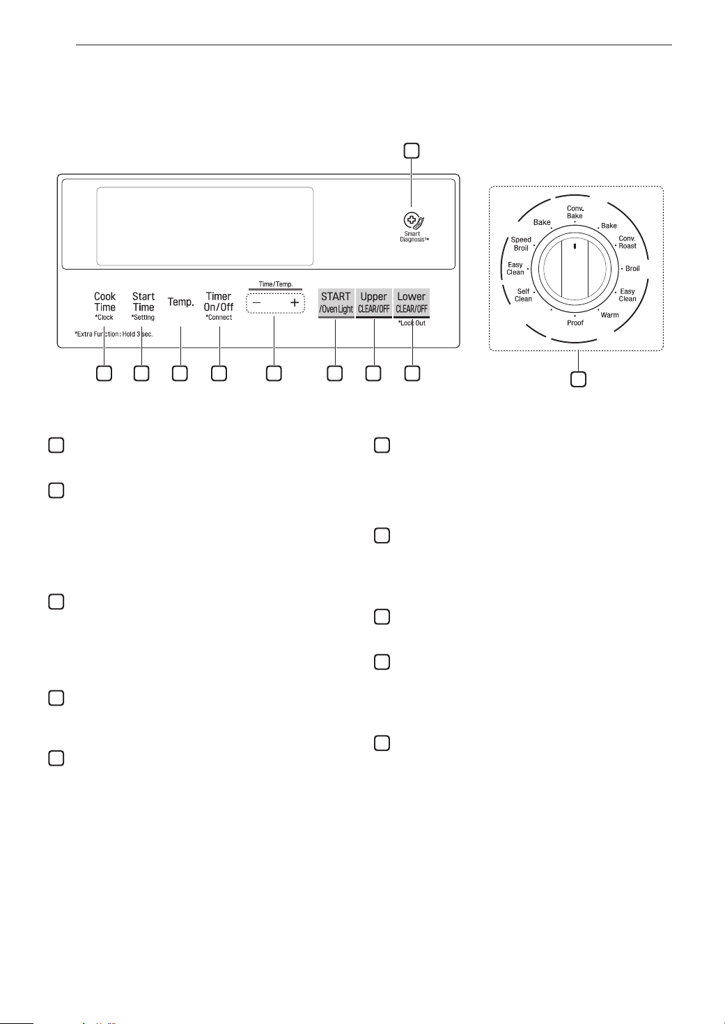
Control Panel Overview
2
3 4 5 6 7 8 9
1
/RZHU
8SSHU
/RZHU
5HPRWH
6WDUW
FRPPRQ
/RZHU
10
1
Smart Diagnosis
TM
Use during the Smart Diagnosis feature.
2
Cook Time / Clock
•Press the button to set the desired amount of time
for food to cook. The oven shuts off when the set
cooking time runs out.
•Press and hold button for three seconds to set the
time of day.
3
Start Time / Setting
•Press the button to set the delayed timed cook. The
oven starts at the set time.
•Press and hold button for three seconds to select
and adjust oven settings.
4
Temp.
•Press the button to change the oven or meat probe
temperature during cooking.
5
Timer On/Off / Connect
•Press the button to set or cancel automatic timer.
•Press and hold button for three seconds to connect
to Wi-Fi network.
6
- /+
Press the plus button to increase cooking time or
oven temperature.
Press the minus button to decrease cooking time or
oven temperature.
7
START / Oven Light
•Press the button to start all oven features.
•Press the button to manually turn the oven light on/
off.
8
Upper CLEAR/OFF
Press the button to end all upper oven features.
9
Lower CLEAR/OFF / Lock Out
•Press the button to end all lower oven feature.
•Press and hold button for three seconds to lock the
door and control panel.
10
Oven Mode Knob
Turn the knob to select oven operating mode.
OPERATION
27
Changing Oven Settings
Clock
The clock must be set to the correct time of day in
order for the automatic oven timing functions to work
properly.
Press and hold Cook Time for three seconds.
1
CLO shows in the display.
Press plus(+) or minus(-) to select the desired
2
time. Plus(+) to increase the time and minus(-)
to decrease the time.
Press Start to enter the time and start the clock.
3
NOTE
•The time of day cannot be changed during a
timed baking or self-clean cycle.
Oven Light
The interior oven light automatically turns on when
the door is opened. Press Oven Light to manually
turn the oven light on.
NOTE
The oven light cannot be turned on if the Self
Clean function is active.
Minimum & Maximum Default
Settings
All of the features listed have a minimum and a
maximum time or temperature setting that may be
entered into the control. An entry acceptance beep
sounds each time a control key is pressed.
An entry error tone (two short tones) sounds if the
entry of the temperature or time is below the minimum
or above the maximum setting for the feature.
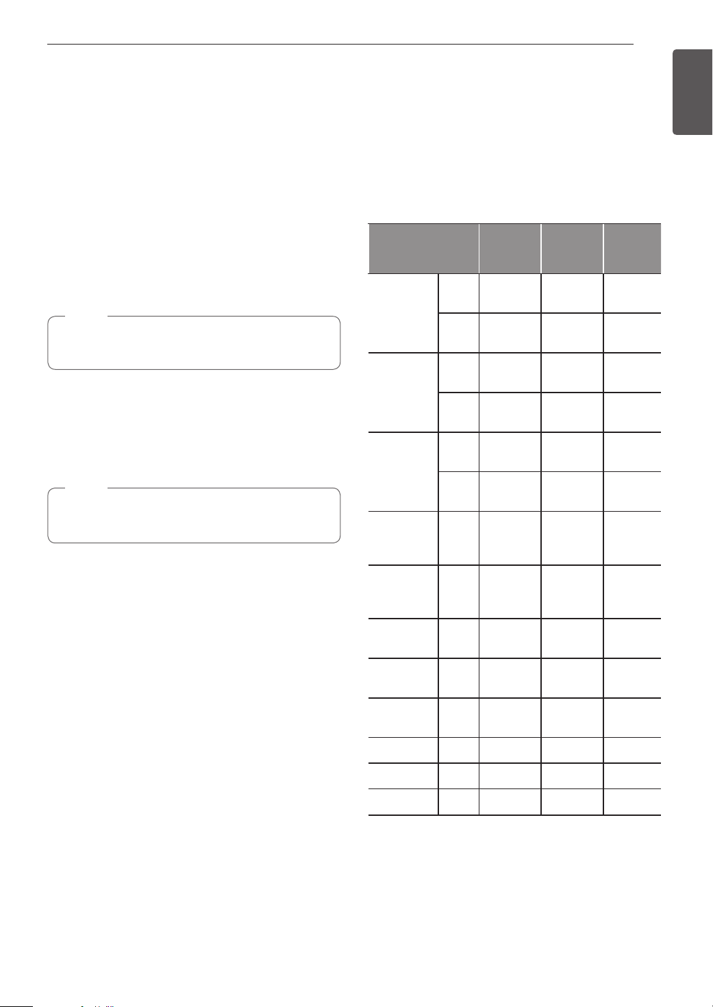
Feature
Clock
Timer
Cook Time
Conv. Bake
min.
Temp. /
Time
12 Hr.
24 Hr.
12 Hr. 0:10 min.
24 Hr. 0:10 min.
12 Hr. 1:00 min.
24 Hr. 1:00 min.
1:00
Hr. / min.
0:00
Hr. / min.
300 °F /
150 °C
max.
Temp. /
Time
12:59
Hr. / min.
23:59
Hr. / min.
11:59
Hr. / min.
11:59
Hr. / min.
11:59
Hr. / min.
11:59
Hr. / min.
550 °F /
285 °C
Default
350 °F
(*325 °F)/
12 Hr.
ENGLISH
Conv.
Roast
Speed Broil
& Broil
Bake
Proof 1:00 min.
Warm 3 Hr.
Self Clean 3 Hr. 5 Hr. 4 Hr.
EasyClean
* Using Auto Conversion
•Default cook mode times are without setting cook
time.
®
300 °F /
150 °C
Lo
400 °F
170 °F /
80 °C
550 °F /
285 °C
Hi
500 °F
550 °F /
285 °C
11:59
Hr. / min.
350 °F
(*325 °F)/
12 Hr.
Hi /
3 Hr.
350 °F /
12 Hr.
10 min.
28
OPERATION
Timer On/Off
The Lower Timer On/Off serves as an extra timer in
the kitchen that beeps when the set time has run out.
It does not start or stop cooking.
The Timer On/Off feature can be used during any of
the oven control function.
Setting the Timer (for example to set 5 minutes)
Press Timer On/Off. 0:00 with HR inside it
1
appears and Timer flashes in the display.
Press plus(+) or minus(-) to select the desired
2
time. Plus(+) increases the time and minus(-)
decreases the time.
Press Timer On/Off or Start to start the Timer.
3
The remaining time countdown appears in the
display.
When the set time runs out, End shows in the
4
display. The indicator tones sound every
15 seconds until Timer On/Off is pressed.
NOTE
•If the remaining time is not in the display, recall
the remaining time by pressing Timer On/Off.
•Press Timer On/Off twice to set the time in
minutes and seconds.
•Press Timer On/Off once to set the time in
hours and minutes.
Cancelling the Timer
Press Timer On/Off once.
1
Connect
The Connect button is used to connect the appliance
to a home Wi-Fi network.
Press Upper CLEAR/OFF and Lower CLEAR/
1
OFF.
Press and hold Timer On/Off for 3 seconds.
2
The power-on chime sounds, Set appears in the
3
display, and the Wi-Fi icon ( ) blinks.
Settings
Press and hold Start Time for three seconds.
Then press the Start Time key repeatedly to toggle
through and change oven settings.
The Settings key allows you to:
•set the hour mode on the clock (12 or 24 hours)
•enable/disable convection auto conversion
•adjust the oven temperature
•activate/deactivate the preheating alarm light
•set the beeper volume
•switch the temperature scale between Fahrenheit
and Celsius
Setting the Hour Mode
The control is set to use a 12-hour clock. To reset the
clock to 24-hour mode, follow the steps below.
Press and hold Start Time for three seconds.
1
Press plus(+) or minus(-) to set the desired
2
hour mode on the clock.
Press Start to accept the desired change.
3
Setting Convection Auto Conversion
When Conv. Bake and Conv. Roast are selected,
Convection Auto Conversion automatically converts the
standard recipe temperature entered to a convection
temperature by subtracting 25 °F / 14 °C. This
auto-converted temperature shows on the display. For
example, select Conv. Bake, enter 350 °F, and 325 °F
shows on the display after preheat.
Convection Auto Conversion is enabled by default. To
change the setting, follow these instructions.
Press and hold Start Time for three seconds.
1
Then press Start Time repeatedly until Auto
appears in the display
Press plus(+) or minus(-) to enable or disable
2
the feature.
Press Start to accept the change.
3
Register the appliance on the Wi-Fi network
4
using the smart phone app. (See page 42.)
To disconnect the appliance from the network,
5
press and hold Timer On/Off for 3 seconds.

OPERATION
29
Adjusting the Oven Temperature
Your new oven may cook differently from the one
it replaced. Use your new oven for a few weeks to
become more familiar with it before changing the
temperature settings. If after familiarizing yourself with
the new oven, you still think that it is too hot or too
cold, you can adjust the oven temperature yourself.
NOTE
To begin, either raise or lower the thermostat
15 °F (8 °C). Try the oven with the new setting. If
the oven still needs adjustment, raise or lower the
thermostat again, using the first adjustment as a
gauge. For example, if the adjustment was too
much, raise or lower the thermostat 10 °F (5 °C).
If the adjustment was not enough, raise or lower
the thermostat 20 °F (12 °C). Proceed in this way
until the oven is adjusted to your satisfaction.
Press and hold Start Time for three seconds.
1
Then press Start Time repeatedly until U_AJ or
L_AJ appears in the display.
To increase the temperature, press plus (+) until
2
the desired amount appears in the display.
To decrease the temperature, press minus (-)
until the desired amount appears in the display.
Adjusting the Beeper Volume
Press and hold Start Time for three seconds.
1
Then press Start Time repeatedly until BEEP
appears in the display.
Press plus(+) or minus(-) to select the desired
2
volume.
Press Start to accept the change.
3
Selecting Fahrenheit or Celsius
Set the oven temperature display to show either
Fahrenheit (°F) or Celsius (°C) units. The oven
defaults to Fahrenheit unless changed by the user.
Press and hold Start Time for three seconds.
1
Then press Start Time repeatedly until Unit
appears in the display.
Press plus(+) or minus(-) to select
2
F(Fahrenheit) or C(Centigrade).
Press Start to accept the change.
3
ENGLISH
Press Start to accept the change.
3
NOTE
•This adjustment does not affect the broiling
or Self Clean temperatures. The adjustment
is retained in memory after a power failure.
The oven temperature can be increased (+) or
decreased (-) as much as 35 °F or 19 °C.
•Once the temperature is increased or
decreased, the display shows the adjusted
temperature until it readjusts.
Turning the Preheat Alarm Light On/Off
When the oven reaches its set-temperature, the
preheating alarm light flashes 5 times or until the
oven door is opened.
You can activate or deactivate the preheating alarm
light.
Press and hold Start Time for three seconds.
1
Then press Start Time repeatedly until PrE
appears in the display.
Press plus(+) or minus(-) to turn the function
2
on/off.
Lock Out
The Lock Out feature automatically locks the oven
door and prevents most oven controls from being
turned on. It does not disable the clock, timer or the
interior oven light.
Press and hold Lower CLEAR/OFF for three
1
seconds.
The lock melody sounds, Loc appears in the
2
Display and the lock icon
Once the oven door is locked, the lock
3
indicator stops blinking and remains on.
To deactivate the Lock Out feature, press and
4
hold Lower CLEAR/OFF for three seconds. The
unlock melody sounds and the door and the
controls unlock.
blinks in the display.
Press Start to accept the change.
3
30
OPERATION
Start Time (Delayed Timed Cook)
The automatic timer of the Delayed Timed Cook
function turns the oven on and off at the time you
select. This feature can be used with the Bake, Conv.
Bake and Conv. Roast modes.
Setting a Delayed Timed Cook
For example, to bake at 300 °F and delay the start
of baking until 4:30, first set the clock for the correct
time of day.
Turn the oven mode knob to select the Bake
1
mode. 350 °F appears in the display.
Set the temperature: press minus(-) until 300 °F
2
appears in the display.
Press Cook Time and press plus (+) or minus (-)
3
to set the baking time.
Press Start Time.
4
Set the start time: press plus(+) until 4:30
5
appears in the display.
Press Start. A short beep sounds and Timed
6
Delay and the start time appear in the display.
The oven begins baking at the set start time.
Cook Time (Timed Cook)
Set the oven to cook for a specific length of time
using the Timed Cook feature. This feature can only
be used with the Bake, Conv. Bake and Conv. Roast
modes.
Setting the Cook Time Function
For example, to bake at 300 °F for 30 minutes, first
set the clock to the correct time of day.
Turn the oven mode knob to select the Bake
1
mode. 350 °F appears in the display.
Set the oven temperature. For this example,
2
press minus(-) until 300 °F appears in the
display.
Press Cook Time. Timed flashes in the display.
3
Bake, 0:00 and 300 °F appear in the display.
Set the baking time: press plus(+) until 30:00
4
appears in the display. The baking time can be
set for any amount of time between 1 minute
and 11 hours and 59 minutes.
Press Start.
5
NOTE
•To cancel the Delayed Timed Cook function,
Press Clear/Off at any time.
•To change the cooking time, repeat step 3 and
press Start.
•If the oven clock is set as a 12-hour clock, you
can delay the cook time for 12 hours. If the
oven clock is set as a 24-hour clock, you can
delay the cook time for 24 hours.
The oven will continue to cook for the set amount
of time and then turn off automatically. When the
cooking time has elapsed:
•End and the time of day show in the display.
•The cook-end indicator tone sounds every 60
seconds until Clear/Off is Pressed.
CAUTION
•Use the automatic timer when cooking cured or
frozen meats and most fruits and vegetables.
Foods that can easily spoil, such as milk, eggs,
fish, meat or poultry, should be chilled in the
refrigerator. Even when chilled, they should
not stand in the oven for more than 1 hour
before cooking begins, and should be removed
promptly when cooking is completed.
•Eating spoiled food can result in sickness from
food poisoning.
The oven will continue to cook for the set amount
of time and then turn off automatically. When the
cooking time has elapsed:
•End and the time of day show in the display.
•The cook end indicator tone sounds every 60
seconds until Clear/Off is Pressed.
Changing the Cook Time during Cooking
For example, to change the cook time from 30
minutes to 1 hour and 30 minutes, do the following.
Press Cook Time.
1
Change the baking time: press plus(+) until
2
1 hour and 30 minutes appears in the display.
Press Start to accept the change.
3
 Loading...