

LG LSU243HLV Extended Piping, LSN363HLV, LS243HLV, LS303HLV, LS363HLV Engineering Manual
...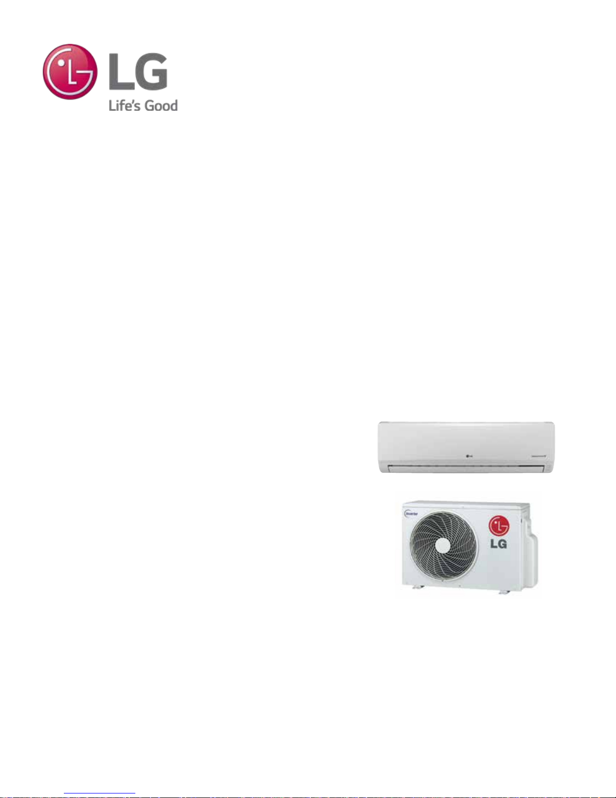
SINGLE ZONE WALL MOUNTED
EXTENDED PIPING ENGINEERING MANUAL
Single Zone Wall Mount Systems
2 to 2-3/4 Tons

PROPRIETARY DATA NOTICE
This document, as well as all reports, illustrations, data, information,
and other materials are the property of LG Electronics U.S.A., Inc., and are
disclosed by LG Electronics U.S.A., Inc. only in confidence.
This document is for design purposes only.
A summary list of safety precautions is on page 4.
For more technical materials such as submittals, catalogs, installation,
owner’s, and service manuals, visit www.lghvac.com.
For continual product development, LG Electronics U.S.A., Inc., reserves the right to change specifications without notice.
© LG Electronics U.S.A., Inc.
About LG Electronics, Inc.
LG Electronics, Inc. is a global leader and technology innovator
in consumer electronics, mobile communications, and home
appliances. LG Electronics, Inc. comprises five business units—
Home Entertainment, Mobile Communications, Air Conditioning,
Business Solutions, and Home Appliance. LG is one of the world’s
leading producers of flat panel televisions, audio and video products,
mobile handsets, air conditioners, and washing machines. LG’s
commercial air conditioning business unit was established in 1968
and has built its lineup of residential and commercial products to
include VRF, Multi F, duct-free split systems, packaged terminal air
conditioners (PTACs), and room air conditioners. In 2011, the air
conditioning and energy solutions business unit grew to include LED
lighting and solar products. For more information, visit www.lg.com.
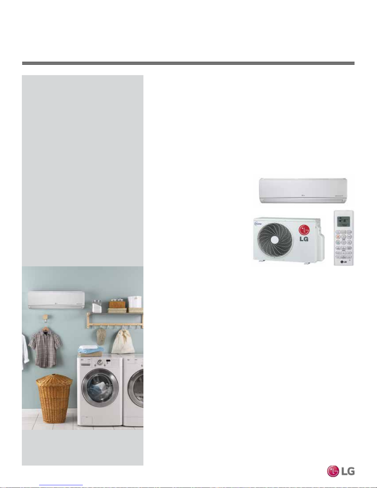
Duct Free Split (DFS) Technology
LG HVAC systems offer a range of solutions that are cost efficient,
quiet and attractive. Duct-Free Split (DFS) systems are “split” into
indoor and outdoor units, and provide a smart alternative to both
central HVAC and window-mounted air conditioners. These inverter
heat pump systems are available in a variety of configurations to suit
different cooling and heating situations. Installation by a qualified
HVAC contractor is safe and easy – little to no duct work or sheet
metal is required.
Inverter Systems
LG Single Zone Wall Mounted Extended Piping air-source systems
offer the opportunity to minimize ductwork in the same configuration.
The systems offer zoning without the need for zone damper systems.
LG Single Zone Wall Mounted Extended Piping systems’ advanced
controls provide exceptional building dehumidification and temperature control, and can rapidly adapt system operating parameters
to the ever changing building load. LG Single Zone Wall Mounted
Extended Piping systems are easy to design, install, and maintain.
The modular design allows occupants to control their environmental
condition, providing individualized control of the setpoint temperature
and allowing occupants to condition only the occupied zones.
Quality Commitment
LG is committed to the success of Duct-Free Split projects. We
provide industry leading technical support during installation and
commissioning. LG offers a variety of classes designed for installers
and servicers to ensure that every system installation is completed
successfully.
Classes are conducted at LG’s training centers and in field locations
at various times throughout the year and upon special request.
Introduction
Due to our policy of continuous product innovation, some specications may change without notication.
LG Electr onics U.S.A., Inc., Englewood Cl iffs, NJ. All r ights reserved. “LG” is a registered tra demark of LG Corp.
©
3

TABLE OF CONTENTS
DANGER
CAUTION
Introduction ..................................................................................................................................................................................................5
Architectural Appeal .....................................................................................................................................................................................6
Product Data ............................................................................................................................................................................................7-24
Product Features and Benefits ....................................................................................................................................................................8
Unit Nomenclature ......................................................................................................................................................................................9
General Data .......................................................................................................................................................................................10-11
Electrical Data ..........................................................................................................................................................................................12
Functions, Controls, Options .....................................................................................................................................................................13
Outdoor Unit Dimensions ..........................................................................................................................................................................14
Outdoor Unit Center of Gravity / Corner Weight .........................................................................................................................................15
Indoor Unit Dimensions .............................................................................................................................................................................16
Acoustic Data ......................................................................................................................................................................................17-18
Refrigerant Flow Diagrams ...................................................................................................................................................................19-20
Indoor Unit Wiring Diagrams .....................................................................................................................................................................21
Outdoor Unit Wiring Diagrams ..............................................................................................................................................................22-23
Accessories ..............................................................................................................................................................................................24
Performance Data ..................................................................................................................................................................................25-37
Cooling Capacity ..................................................................................................................................................................................26-27
Heating Capacity .................................................................................................................................................................................28-29
Maximum Heating Capacity ..................................................................................................................................................................30-31
Air Flow and Temperature Distributions Graphs .................................................................................................................................... 32-37
Application Guidelines ..........................................................................................................................................................................38-44
Equipment Selection Procedure ................................................................................................................................................................39
Building Ventilation Design Guide ........................................................................................................................................................40-41
Placement Considerations ...................................................................................................................................................................42-44
Refrigerant Piping Design & Layout Best Practices ............................................................................................................................45-53
Refrigerant Piping Design .........................................................................................................................................................................46
Installation & Best Layout Practices .....................................................................................................................................................48-52
Electrical Connections ..............................................................................................................................................................................53
Technical Data .......................................................................................................................................................................................54-56
Mechanical Specifications .........................................................................................................................................................................55
Acronyms ..................................................................................................................................................................................................56
Single Zone High Wall Mounted Extended Piping Engineering Manual
TABLE OF SYMBOLS
This symbol indicates an imminently hazardous situation which, if not avoided, will result in death or serious injury.
This symbol indicates a potentially hazardous situation which, if not avoided, could result in death or serious injury.
This symbol indicates a potentially hazardous situation which, if not avoided, may result in minor or moderate injury.
This symbol indicates situations that may result in equipment or property damage accidents only.
This symbol indicates an action should not be completed.
Due to our policy of continuous product innovation, some specications may change without notication.
LG Electr onics U.S.A., Inc., Englewood Cl iffs, NJ. All r ights reserved. “LG” is a registered tra demark of LG Corp.
4 | INTRODUCTION
©

INTRODUCTION
“Architectural Appeal” on page 6
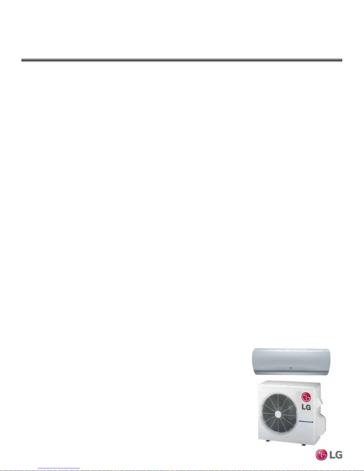
ARCHITECTURAL APPEAL
Convergence of Technological Innovation with Flexibility and Style
Single Zone Wall
Benefits of Single Zone Wall
Mounted Extended Piping Systems
• Available from 22,000 - 33,000 Btu/h
• Inverter technology
• All season use - heat pump models for both
cooling and heating capabilities
• Operating range for outdoor units of 14°F to
118°F (DB) in cooling and -4°F to 75°F (WB)
in heating
• Operating range for indoor units of 53°F to
75°F in (WB) cooling and 60°F to 86°F (DB)
in heating
• Quiet operation inside and outside
• Duct-free split system
Mounted Extended
Piping Systems
Single zone wall mounted extended piping
systems are among the industry’s best
air-conditioning units. Choosing an LG
single zone wall mount product provides
a system designer an edge to engineer a
system with individual control, and design
flexibility with advanced controls.
Single zone systems are available in a
nominal capacity range of 2 to 2-3/4 tons.
These are best suited for applications
with zones that require heating or cooling,
such as residential, and small business
office buildings. Single zone wall mount
outdoor and indoor units are available in
208–230V/60Hz/1Ph.
Adaptable and Flexible
Single zone wall mounted extended piping
systems allow cooling or heating for the
entire residence or just a single room
without the need for evasive ductwork.
There is no tearing down of walls or altering the homes appearance. Long refrigerant piping lengths allow for extra design
flexibility in indoor unit installation.
These units may be used for a number of
residential or commercial environments
such as:
• Older homes
• New home construction
• Office buildings
• Restaurants
• Hospitals / Medical facilities
• Schools
• Nursing homes
• Retail establishments
• Place of worship
Single Zone High Wall Mounted Extended Piping Engineering Manual
Inverter Technology
Inverter variable-speed DFS systems are
measurably quieter and consume less
energy than conventional air conditioners. The inverter compressor ramps up or
down to match the required room capacity
and maintain the comfort level. When the
selected temperature is reached, the inverter compressor operates at low speed
to maintain that comfort level, thereby
using less energy.
Due to our policy of continuous product innovation, some specications may change without notication.
LG Electr onics U.S.A., Inc., Englewood Cl iffs, NJ. All r ights reserved. “LG” is a registered tra demark of LG Corp.
6 | INTRODUCTION
©

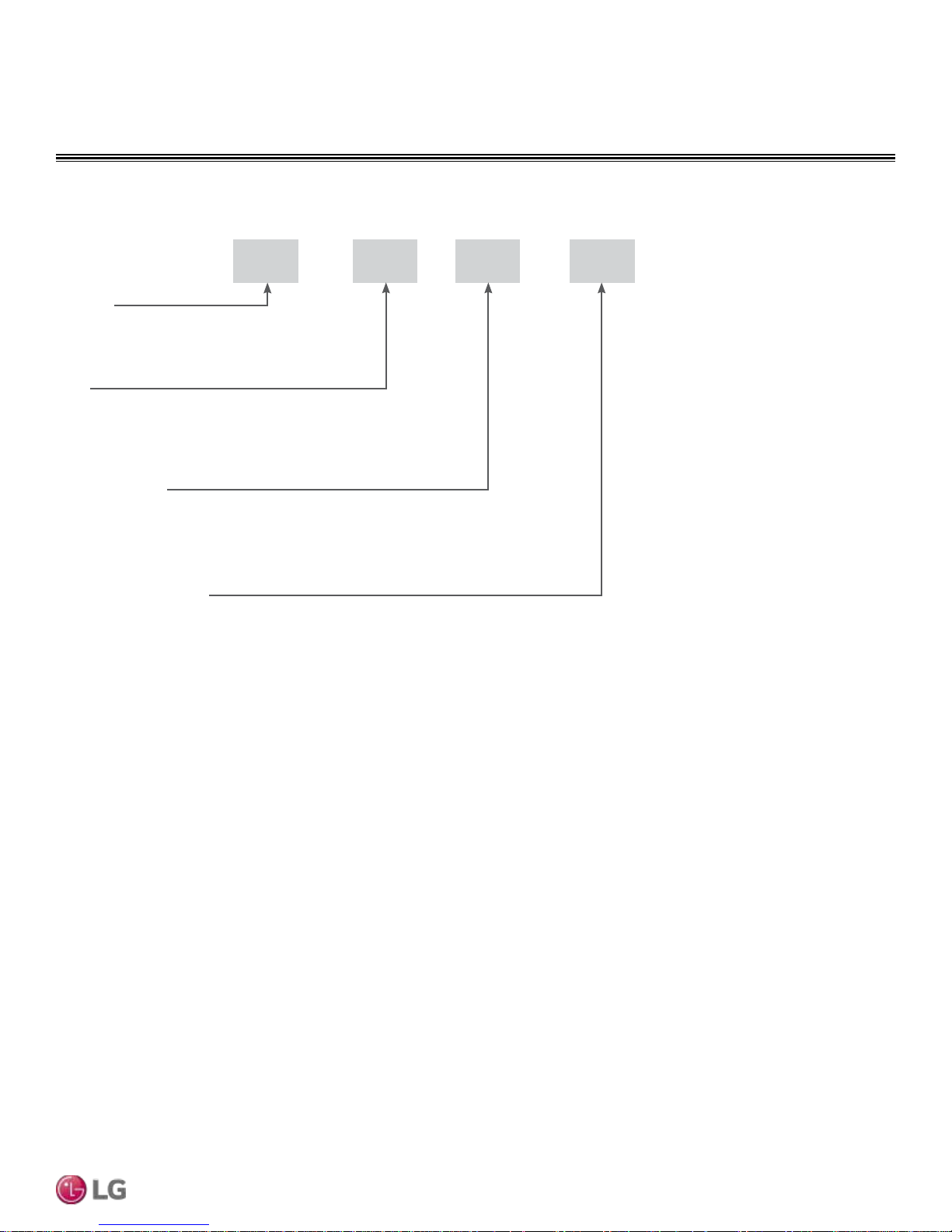
PRODUCT DATA
“Product Features and Benefits” on page 8
“Unit Nomenclature” on page 9
“General Data” on page 10
“Electrical Data” on page 12
“Functions, Controls, Options” on page 13
“Outdoor Unit Dimensions” on page 14
“Outdoor Unit Center of Gravity / Corner Weight” on page 15
“Indoor Unit Dimensions” on page 16
“Acoustic Data” on page 17
“Refrigerant Flow Diagrams” on page 19
“Indoor Unit Wiring Diagram” on page 21
“Outdoor Unit Wiring Diagrams” on page 22
“Accessories” on page 24
PRODUCT FEATURES AND BENEFITS
Single Zone Systems
Single zone wall mounted extended piping
systems are equipped with inverter components that offer superior load matching
and long piping installation. The product
works for optimizing power consumption in
residential and small office buildings. Utilizing multiple indoor wall mount units each
with custom temperature controls allow for
precise temperature settings in each zone
of the building. Single zone systems allow
flexibility in interior design and complement
any decor.
Inverter Driven
The twin rotary compressors are optimized
to maximize compressor efficiency, which
reduces power consumption and monthly
utility bills. This latest inverter technology
allows single zone system outdoor units to
vary the compressor motor shaft speed to
deliver an appropriate amount of cooling to
the indoor unit. Precise refrigerant volume
delivery translates into long periods with coil
surface temperatures below dew point and
minimizes compressor and fan component
run time. Occupants remain comfortable
while utility costs are reduced.
Low Sound Levels
When outdoor units operate fully loaded,they
have one of the quietest sound levels in
the industry. Sound is almost undetectable
during off-peak operation. To promote a
quiet, comfortable environment, the single
zone system indoor units operate at sound
levels as low as 37 dB(A) and outdoor units
as low as 55 dB(A) at full load. LG customers often ask if the outdoor unit is running
after commissioning is complete. All rotating
components are soft-started by the controller using digitally controlled inverters, which
reduce undesirable noise caused by fans
and compressors cycling on and off.
Comfort Control at Its
Best
Tight temperature control through precise
load matching maximizes the time that
the indoor units remove moisture. Unlike
traditional air conditioning control systems,
which use thermostatic controls to maintain
room temperatures, LG single zone Inverter
controls continuously adjust the indoor unit
fan speed and refrigerant flow, indirectly providing lower and more consistent humidity
levels in the conditioned space. The longer
Single Zone Wall Mounted Extended Piping Engineering Manual
the indoor coil temperature is below the
dew-point of the room in conjunction with air
movement across the coil, the space humidity level will vary little, compared to technologies that cycle fans and compressors on and
off multiple times per hour. The outdoor unit
responds by varying the compressor speed
and outdoor fan motors as needed to maintain system operating pressure. As a result,
the single zone systems deliver precise
space temperature control.
Simplified Installation
Cooling and heating applications that use
single zone systems simplify and reduce
the mechanical and control system design
time. The designer no longer has to be
concerned with interconnecting chilled and
condenser water piping, air-distribution duct
systems,matching and selecting chillers,
towers,pumps, coils, fans, air handlers, or
Variable Air Volume (VAV) boxes.
Operating Range
Single zone systems have a nominal capacity range of 2 to 2-3/4 tons (depending on
outdoor/indoor units).
Operating ranges for single zone systems:
Cooling: 14°F DB to 118°F DB
Heating: -4°F WB to 65°F WB
Installing an optional Low Ambient Wind
Baffle Kit will allow operation down to 0°F in
cooling mode for all single zone systems.
Compact Size
Single zone outdoor units have the following
footprints:
LSU243HLV, LSU303HLV, LSU363HLV
(WxHxD (in)) 34-1/4 x 31-1/2 x 12-5/8.
Fin Design with GoldFin™ Coating
All single zone outdoor units are provided
with large surface coils made of copper
tubes with louvered aluminum fins designed
to maximize unit operating efficiency over a
wide range of ambient conditions.
Standard from the factory, every single zone
outdoor unit coil fin surface is coated with
LG’s exclusive GoldFin™ anti-corrosive
coating designed to prevent natural surface
corrosion of the aluminum fins. This maintains heat transfer properties of the coil for
an extended time.
A hydrophilic coating is applied to the
outdoor unit coil fin surface over the GoldFin
coating. This coating enhances the development of heavier water droplets gathering
on the fin surface. As a result, the droplets
roll off the fin surfaces, delaying the point
when frost forms on the coil surface during
heating operation. This coating also makes it
possible to easily clean the outdoor unit coil
using a mild soap.
Other Features
• Inverter variable speed compressor
• Jet Cool / Jet Heat
• Dehumidifying mode
• Chaos Wind
• Auto restart
• Auto operation
• Self-cleaning indoor coil
• Condensate sensor connection
• Cooling only function
• Precision load matching
• Meets AHRI 210/240
Due to our policy of continuous product innovation, some specications may change without notication.
LG Electr onics U.S.A., Inc., Englewood Cl iffs, NJ. All r ights reserved. “LG ” is a re gistered trademark of LG C orp.
8 | PRODUCT DATA
©
Single Zone Indoor and Outdoor Units
LS N 243 HLV
Family
LS = Wall Mounted
Type
N = Indoor Wall Mount Unit
U = Outdoor Heat Pump Unit
Nominal Capacity
(Nominal cooling capacity in Btu/h)
243 = 22,000 303 = 30,000 363 = 33,000
UNIT NOMENCLATURE
Product Data
Indoor/Outdoor Product
HLV - Extended Piping
Due to our policy of continuous product innovation, some specications may change without notication.
LG Electr onics U.S.A., Inc., Englewood Cl iffs, NJ. All r ights reserved. “LG ” is a re gistered trademark of LG C orp.
©
PRODUCT DATA | 9

GENERAL DATA
Single Zone Wall Mounted Extended Piping System Pairing Table
The following tables show the available outdoor and indoor units, along with the factory provided controllers.
Table 1: Single Zone Wall Mounted Extended Piping System Pairing Table
Outdoor Unit Model Indoor Unit Model Controller
LSU243HLV
LSU303HLV
LSU363HLV
LSN243HLV
LSN303HLV
LSN363HLV
AKB74955602
Single Zone Wall Mounted Extended Piping Engineering Manual
Due to our policy of continuous product innovation, some specications may change without notication.
LG Electr onics U.S.A., Inc., Englewood Cl iffs, NJ. All r ights reserved. “LG ” is a re gistered trademark of LG C orp.
10 | PRODUCT DATA
©
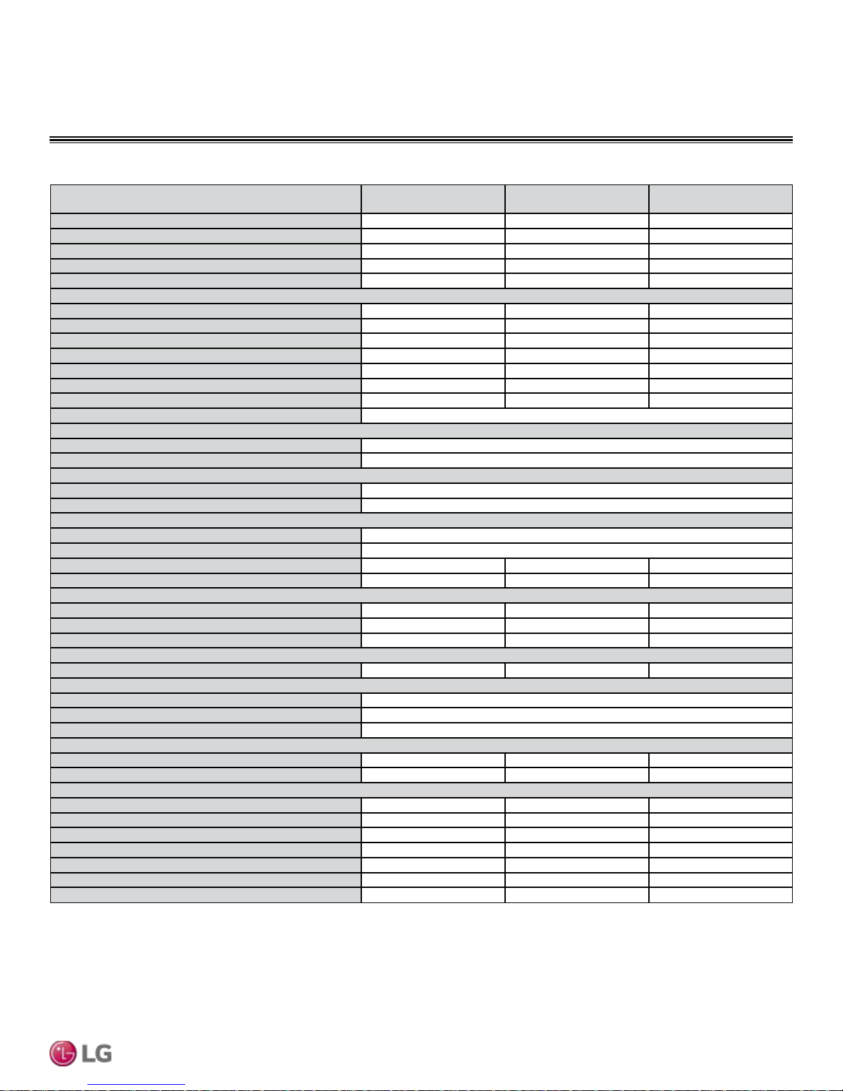
Table 2: Single Zone Wall Mounted Extended Piping Specications.
System (Model) (Indoor Unit / Outdoor Unit)
Cooling Capacity
1
(Min/Rated/Max) (Btu/h)
Cooling Power Input1 (Rated) (kW)
Heating Capacity (Min/Rated/Max) (Btu/h)
Heating Power Input1 (Rated) (kW)
COP
Maximum Heating Capacity (Btu/h)
Outdoor 17°F (WB)/Indoor 70°F (DB)
Outdoor 5°F (WB)/Indoor 70°F (DB)
Outdoor 0°F (WB)/Indoor 70°F (DB)
Outdoor -4°F (WB)/Indoor 70°F (DB)
EER
SEER
HSPF
Power Supply V, Ø, Hz2
Outdoor Unit Operating Range
2
Cooling (°F DB)
Heating (°F WB)
Indoor Unit Operating Range
2
Cooling (°F WB)
Heating (°F DB)
Unit Data
Refrigerant Type
3
Refrigerant Control
IDU Sound Pressure Level dB(A) (H/M/L/SL)4
ODU Sound Pressure Level dB(A)
4
Unit Weight (lbs.)
IDU (Net/Shipping)
ODU (Net/Shipping)
Power Wiring / Communications Cable (No. x AWG)
Compressor
Compressor (Qty.)
Fan
IDU Type x Qty.
ODU Type x Qty.
Motor / Drive
Airflow Rate
IDU (H / M / L [CFM])
ODU (Max. [CFM])
Piping
Liquid (in.)
Vapor (in.)
Condensate Drain O.D. / I.D. (in.)
Additional Refrigerant Charge (oz./ft.)
Pipe Length5 (Minimum/ Maximum) (ft.)
Piping Length5 (no add’l refrigerant, ft.)
Max. Elevation Difference (ft.)
EEV: Electronic Expansion Valve IDU: Indoor Unit ODU: Outdoor Unit
Cooling capacity rating obtained with air entering the indoor unit at 80ºF dry bulb (DB) and 67ºF wet
bulb (WB) and outdoor ambient conditions of 95ºF dry bulb (DB) and 75ºF wet bulb (WB).
Heating capacity rating obtained with air entering the indoor unit at 70ºF dry bulb (DB) and 59ºF wet
bulb (WB) and outdoor ambient conditions of 47ºF dry bulb (DB) and 43ºF wet bulb (WB).
This data is rated 0 ft above sea level with 24.6 of refrigerant line per indoor unit and a 0 ft level
difference outdoor and indoor units.
This unit comes with a dry helium charge.
Power wiring to the ODU is field supplied, solid or stranded, and must comply with the applicable local
and national codes
Due to our policy of continuous product innovation, some specications may change without notication.
LG Electr onics U.S.A., Inc., Englewood Cl iffs, NJ. All r ights reserved. “LG ” is a re gistered trademark of LG C orp.
©
GENERAL DATA
Single Zone Wall Mounted Extended Piping Specications
LS243HLV
(LSN243HLV/LSU243HLV)
3,070 ~ 22,000 ~ 29,515 3,070 ~ 30,000 ~ 34,000 3,070 ~ 33,000 ~ 34,000
1.76 3.0 4.04
3,070 ~ 27,000 ~ 38,898 3,070 ~ 32,000 ~ 38,898 3,070 ~ 35,200 ~ 38,898
2.38 3.1 3.84
11.34 10.32 9.17
27,410 (102%) 32,490 (102%) 35,740 (102%)
23,690 (88%) 28,080 (88%) 30,890 (88%)
22,090 (82%) 26,180 (82%) 28,800 (82%)
20,580 (76%) 24,390 (76%) 26,820 (76%)
12.50 10.00 8.18
21.50 19.00 17.50
11.0 10.0 10.0
49/44/40/37 49/44/40/37 49/44/40/37
55 55 55
39.7/45.2 39.7/45.2 39.7/45.2
2
124.6/132.3 124.6/132.3 124.6/132.3
4 x 18 4 x 18 4 x 18
Twin Rotary (1) Twin Rotary (1) Twin Rotary (1)
Brushless Digitally Controlled/Direct
953/848/706/530 953/848/706/530 953/848/706/530
2,119 2,119 2,119
3/8 3/8 3/8
5/8 5/8 5/8
27/32 / 5/8 27/32 / 5/8 27/32 / 5/8
0.38 0.38 0.38
9.8/164 9.8/164 9.8/164
24.6 24.6 24.6
98.4 98.4 98.4
1
Power Input is rated at high speed.
2
Low Ambient Wind Baffle Kit allows operation down to 0°F in cooling mode.
3
Take appropriate actions at the end of HVAC equipment life to recover, recycle, reclaim or destroy
R410A refrigerant according to applicable regulations (40 CFR Part 82, Subpart F) under section 608
of CAA.
4
Sound Pressure levels are tested in an anechoic chamber under ISO Standard 1996.
5
All power/communication cables to be minimum 18 AWG, 4-conductor, stranded, shielded and must
comply with applicable and national code.
6
Piping lengths are equivalent.
LS303HLV
(LSN303HLV/LSU303HLV)
208-230/60/1
14 to 118
-4 to +65
53 to 75
60 to 86
R410A
EEV
Cross Flow Fan (1)
Propeller (1)
LS363HLV
(LSN363HLV/LSU363HLV)
PRODUCT DATA | 11
Product Data
ELECTRICAL DATA
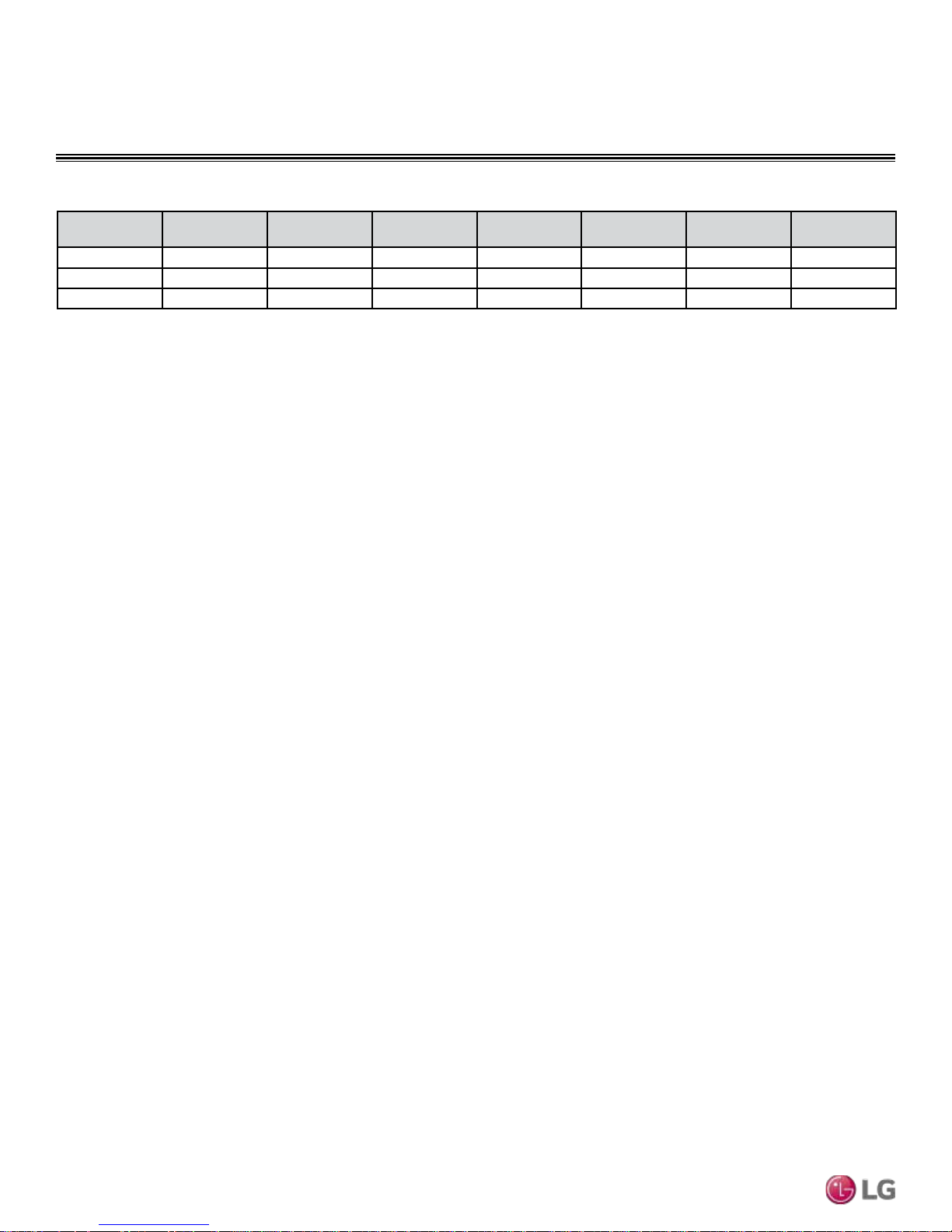
Table 3: Single Zone Wall Mounted Extended Piping Electrical Data
Model Number Nominal Tons Compressor Qty
LS243HLV
LS303HLV
LS363HLV
Voltage tolerance is ±10%.
Maximum allowable voltage unbalance is 2%.
RLA = Rated Load Amps.
2 1 14.6/14.6 1 0.25 19 30
2-1/2 1 14.6/14.6 1 0.25 19 30
2-3/4 1 14.6/14.6 1 0.25 19 30
Compressor (A)
Cool / Heat
MCA = Minimum Circuit Ampacity.
Maximum Overcurrent Protection (MOP) is calculated as follows:
(Largest motor FLA x 2.25) + (Sum of other motor FLA) rounded down
to the nearest standard fuse size.
Fan Qty
Outdoor Unit
Fan (A)
Recommended fuse size: 25A.
MCA (A) MOP (A)
Single Zone Wall Mounted Extended Piping Engineering Manual
Due to our policy of continuous product innovation, some specications may change without notication.
LG Electr onics U.S.A., Inc., Englewood Cl iffs, NJ. All r ights reserved. “LG ” is a re gistered trademark of LG C orp.
12 | PRODUCT DATA
©
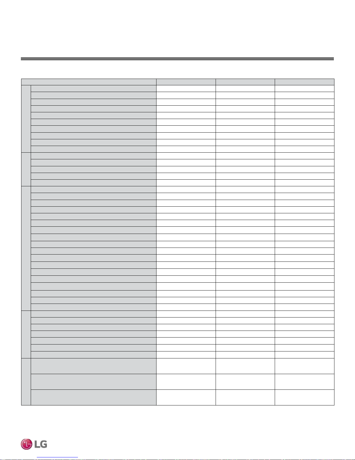
Table 4: Indoor Units—Functions, Controls and Options.
Indoor Unit Type LS243HLV LS303HLV LS363HLV
Air supply outlet
Airflow direction (left/right)
Airflow direction (up/down)
Auto swing (left/right)
Auto swing (up/down)
Airflow steps (fan/cool/heat)
Airow
Auto swing
Auto wind
Jet-cool/heat
Comfort air
Washable anti-fungal
1
Deodorizing filter
2
Plasma
3M Micro Dust filter
Air Purifying
3M Micro Protection filter
2
Drain pump
Electric heater
Defrost
Low ambient
Hot start
Self diagnostics
Outdoor Unit Drain Pan Heater
Dry (Dehumidification operation)
Auto changeover
Auto clean (coil dry)
Functions
Auto restart
Child lock (applicable with wired controller)
Forced operation
Sleep mode
Timer (24hr on/off)
Weekly timer (applicable with wired controller)
Two thermistor control (applicable with wired controller)
Energy saving
Wireless Remote Controller
Simple Controller with Mode Selection
Simple Controller without Mode Selection
LG Programmable Thermostat
Dry contact
Controllers
Central control (LGAP)
PI 485
FUNCTIONS, CONTROLS, OPTIONS
1 1 1
5 Steps 5 Steps 5 Steps
6 Steps 6 Steps 6 Steps
√ √ √
√ √ √
6 / 6 / 6 6 / 6 / 6 6 / 6 / 6
√ √ √
√ √ √
√ / √ √ / √ √ / √
X X X
√ √ √
X X X
X X X
X X X
√ √ √
X X X
X X X
√ √ √
√ √ √
√ √ √
√ √ √
X o o
√ √ √
√ √ √
√ √ √
√ √ √
o o o
√ √ √
√ √ √
√ √ √
o o o
o o o
√ √ √
o o o
o o o
o o o
o o o
o o o
o o o
Product Data
Wi-Fi Module
Water level sensor connection (for optional AG-9300-LG)
Wind baffle kit
Special Function Kit
1
Primary washable filters.
2
Secondary filters.
√ = Standard feature
o = Optional accessory (must be purchased separately)
X = Not available
Due to our policy of continuous product innovation, some specications may change without notication.
LG Electr onics U.S.A., Inc., Englewood Cl iffs, NJ. All r ights reserved. “LG ” is a re gistered trademark of LG C orp.
©
√ √ √
o o o
ZLABGP02A ZLABGP02A ZLABGP02A
• When Dry Contact Mode active, Wi-Fi Function can not be used.
• When changing from Wi-Fi mode to dry contact mode, normal operation resumes in approximately 3 minutes.
PRODUCT DATA | 13
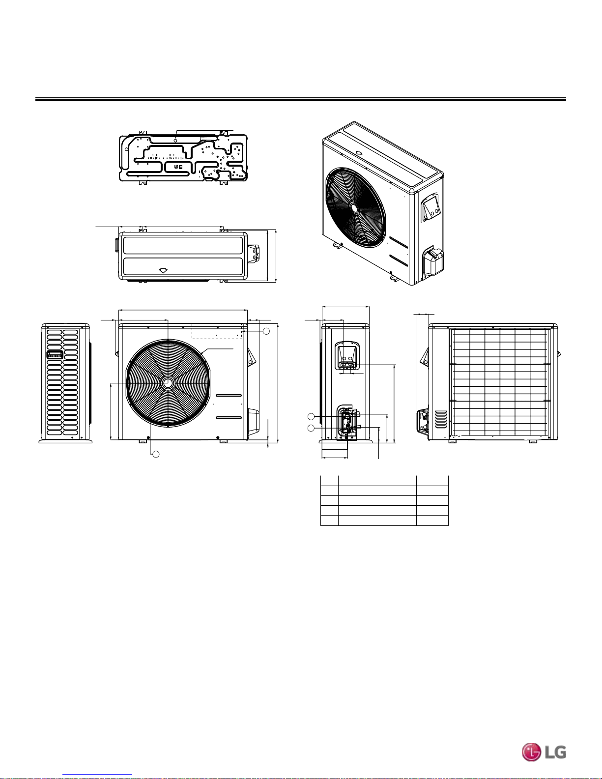
OUTDOOR UNIT DIMENSIONS
LSU243HLV, LSU303HLV, LSU363HLV
Drain Hole 2-Ø13/16
6-15/32 21-1/2
14-3/16
13-13/32
29/32
13-3/32
15-3/32
34-1/4
3-5/32
4
21-1/2
7/8
1
17/32
31-1/2
2
3
Unit : inch (mm)
Single Zone Wall Mounted Extended Piping Engineering Manual
12-19/32
5-7/8
1-25/32
25°
14°
6-25/32
6-29/32
Air Discharge Grille 1
Gas Pipe Connection Port
2
3
Liquid Pipe Connection Port
Control Box
4
2-3/4
20-27/32
7-11/16
4-7/32
Part Name RemarkNo
Due to our policy of continuous product innovation, some specications may change without notication.
LG Electr onics U.S.A., Inc., Englewood Cl iffs, NJ. All r ights reserved. “LG ” is a re gistered trademark of LG C orp.
14 | PRODUCT DATA
©
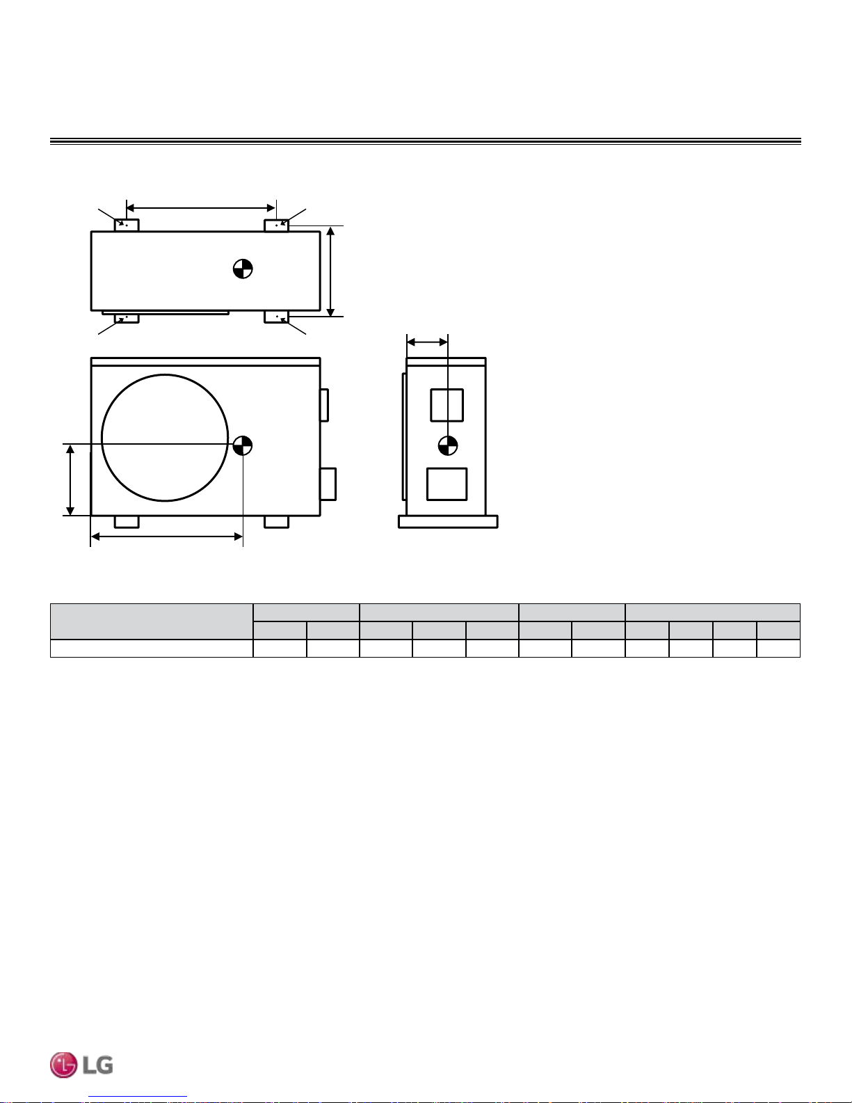
d
OUTDOOR UNIT CENTER OF GRAVITY /
Figure 1: Center of Gravity and Corner Weight Dimensions Diagram.
CORNER WEIGHT
A
B
b
a
Table 5: Center of Gravity and Corner Weight Dimensions.
Model
LSU243HLV, LSU303HLV, LSU363HLV 132.3 124.6 21-3/32 13-25/32 6-23/32 21-1/2 13-13/32 21.2 18.7 39.9 44.8
Shipping Net a b c d e A B C D
D
e
C
Weight (lb.) Center of Gravity (inch) Leg (inch) Corner Weight (lb.)
c
Product Data
Due to our policy of continuous product innovation, some specications may change without notication.
LG Electr onics U.S.A., Inc., Englewood Cl iffs, NJ. All r ights reserved. “LG ” is a re gistered trademark of LG C orp.
©
PRODUCT DATA | 15
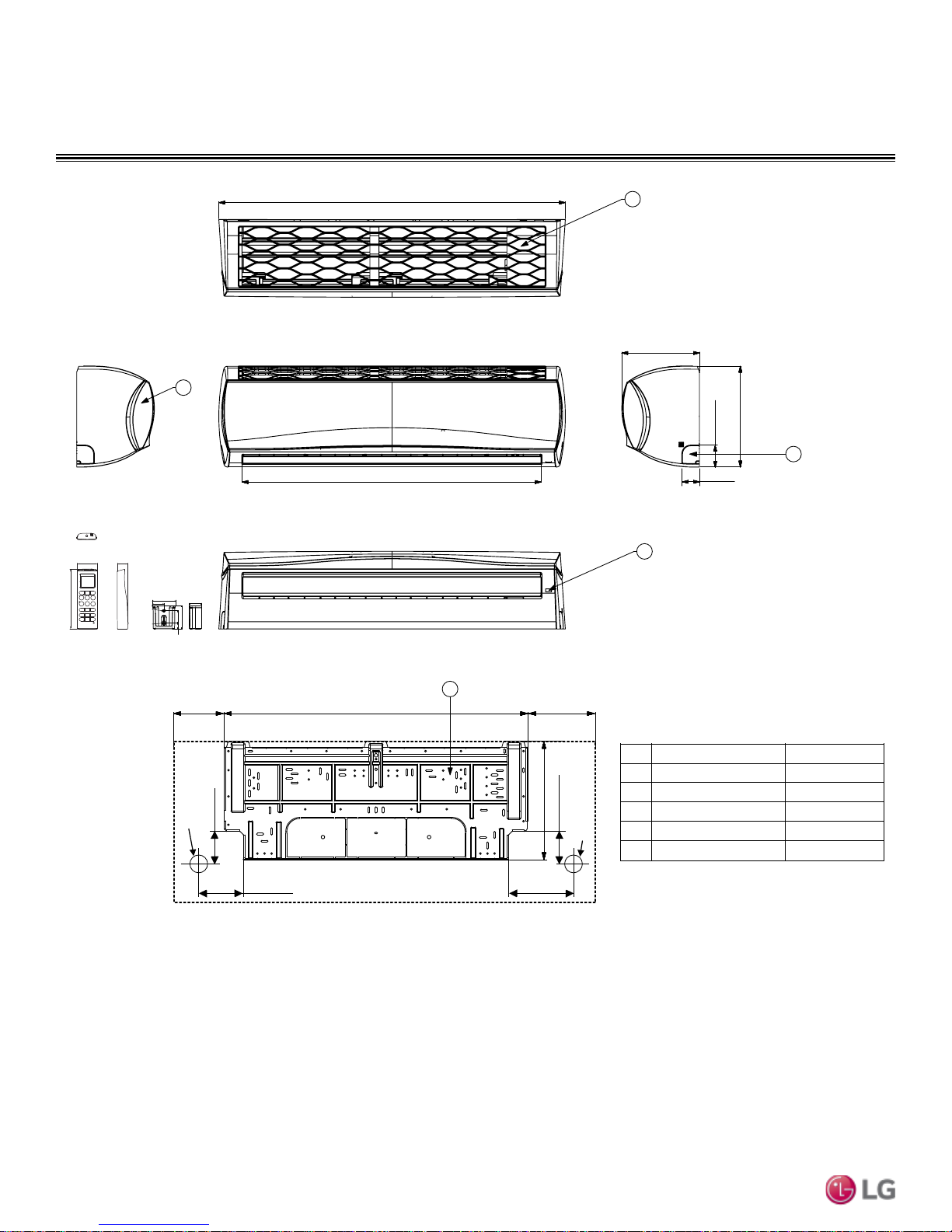
INDOOR UNIT DIMENSIONS
LSN243HLV, LSN303HLV, LSN363HLV
1-3/32
5-31/32
1-1/16
46-7/8
3
10-7/16
1
13-5/8
2-17/32
4
40-9/16
2-11/32
2
2-7/16
1-7/16
1-1/4
1/4 x 1/8
1-9/32
2-13/32
1/8 x 1/4
5/8
5
6-9/16
2-17/32Ø
1-11/16
4-23/32
33-25/32
Single Zone Wall Mounted Extended Piping Engineering Manual
4-23/32
6-9/16
13-3/16
1-11/16
2-17/32Ø
Part NameNo Remark
Front Panel 1
2
Display & Signal Receiver
3
Air Suction Grille
4
Knockout Hole For pipe and cable
5
Installation Plate
Unit: inch
Due to our policy of continuous product innovation, some specications may change without notication.
LG Electr onics U.S.A., Inc., Englewood Cl iffs, NJ. All r ights reserved. “LG ” is a re gistered trademark of LG C orp.
16 | PRODUCT DATA
©

OUTDOOR UNIT ACOUSTIC DATA
3.28 ft
Center of
Outdoor Unit
Octave Band Sound Pressure Level (0dB = 20μPa)
Figure 2: Outdoor Unit Sound Levels
Figure 3: LSU243HLV, LSU303HLV, LSU363HLV
80
70
60
50
40
30
• Measurements are taken 3.28 ft away from the front of the unit.
• Sound pressure levels are measured in dB(A) with a tolerance of ±3.
• Sound pressure levels are tested in an anechoic chamber under
ISO Standard 3745.
• Sound level will vary depending on a range of factors including the
construction (acoustic absorption coefficient) of a particular room in
which the unit was installed.
Table 6: Outdoor Unit Sound Pressure Data
Model H
LSU243HLV 55
LSU303HLV 55
LSU363HLV 55
Product Data
NC-65
NC-60
NC-55
NC-50
NC-45
NC-40
NC-35
NC-30
20
Approximate
Hearing
Threshold
10
63 125 250 500 1000 2000 4000 8000
Octave Band Center Frequency (Hz)
Due to our policy of continuous product innovation, some specications may change without notication.
LG Electr onics U.S.A., Inc., Englewood Cl iffs, NJ. All r ights reserved. “LG ” is a re gistered trademark of LG C orp.
©
NC-25
NC-20
NC-15
PRODUCT DATA | 17
INDOOR UNIT ACOUSTIC DATA
2.62 ft
3.28 ft
Microphone
Octave Band Sound Pressure Level (0dB = 20μPa)
Figure 4: Indoor Unit Sound Levels
Figure 5: LSU243HLV, LSU303HLV, LSU363HLV
80
70
60
50
40
30
• Measurements are taken 3.28 ft away from the front of the unit.
• Sound pressure levels are measured in dB(A) with a tolerance of
±3.
• Sound pressure levels are tested in an anechoic chamber under
ISO Standard 3745.
• Sound level will vary depending on a range of factors including the
construction (acoustic absorption coefficient) of a particular room in
which the unit was installed.
Table 7: Indoor Unit Sound Pressure Data
Model H M L
LSN243HLV 49 44 40
LSN303HLV 49 44 40
LSN363HLV 49 44 40
NC-65
NC-60
NC-55
NC-50
NC-45
NC-40
NC-35
NC-30
20
Approximate
Hearing
Threshold
10
63 125 250 500 1000 2000 4000 8000
Octave Band Center Frequency (Hz)
NC-25
NC-20
NC-15
Single Zone Wall Mounted Extended Piping Engineering Manual
18 | PRODUCT DATA
Due to our policy of continuous product innovation, some specications may change without notication.
LG Electr onics U.S.A., Inc., Englewood Cl iffs, NJ. All r ights reserved. “LG ” is a re gistered trademark of LG C orp.
©
 Loading...