

LG TRUE, LSN090CE, LSU240CE, LSN240CE, LSN180CE User Manual 2
...
LG
Room Air Conditioner
SERVICE MANUAL
LG
MODELS: LSN090CE LSU090CE
LSN120CE LSU120CE
LSN180CE LSU180CE
LSN240CE LSU240CE
LSN090HE LSU090HE
LSN120HE LSU120HE
LSN180HE LSU180HE
LSN240HE LSU240HE
CAUTION
website http://www.lgservice.com
• BEFORE SERVICING THE UNIT, READ THE SAFETY
PRECAUTIONS IN THIS MANUAL.
• ONLY FOR AUTHORIZED SERVICE PERSONNEL.

2 Room Air Conditioner
Air Conditioner Service Manual
TABLE OF CONTENTS
Safety Precautions..........................................................................................................................................3
Dimensions......................................................................................................................................................9
Symbols Used in this Manual.....................................................................................................................9
Indoor Unit..................................................................................................................................................9
Outdoor Unit.............................................................................................................................................11
Installation.....................................................................................................................................................14
Selection of the Best Location..................................................................................................................17
Piping Length and Elevation.....................................................................................................................18
How to Fix Installation Plate.....................................................................................................................19
Drill a Hole in the Wall..............................................................................................................................19
Drain hose junction...................................................................................................................................19
Flaring work and connection of piping.......................................................................................................20
Flaring work..............................................................................................................................................20
Connection of Piping Indoor.....................................................................................................................21
Connection of the Pipes-Outdoor.............................................................................................................26
Connecting the cable between indoor unit and outdoor unit...................................................................27
Connect the Cable....................................................................................................................................27
Checking the drainage and forming the pipings........................................................................................29
Checking the Drainage.............................................................................................................................29
Form the Piping........................................................................................................................................30
AIR PURGING................................................................................................................................................31
Air purging................................................................................................................................................31
Air purging with vacuum pump.................................................................................................................31
Test Running.................................................................................................................................................34
Operation.......................................................................................................................................................35
Function of Controls.................................................................................................................................35
Display Function ......................................................................................................................................39
Self-diagnosis Function............................................................................................................................39
Remote Control Operations......................................................................................................................40
Disassembly..................................................................................................................................................41
Indoor Unit................................................................................................................................................41
Troubleshooting Guide.................................................................................................................................44
Refrigeration Cycle Diagram....................................................................................................................44
2-way, 3-way Valve .................................................................................................................................45
Cycle Parts...............................................................................................................................................51
Electronic Parts........................................................................................................................................52
Schematic Diagram.......................................................................................................................................62
Electric Control Device.............................................................................................................................62
Wiring Diagram.........................................................................................................................................65
Components Location ..............................................................................................................................67
Product Specifications.................................................................................................................................72
Exploded View...............................................................................................................................................74
Replacement Parts List ................................................................................................................................78
Service Manual 3
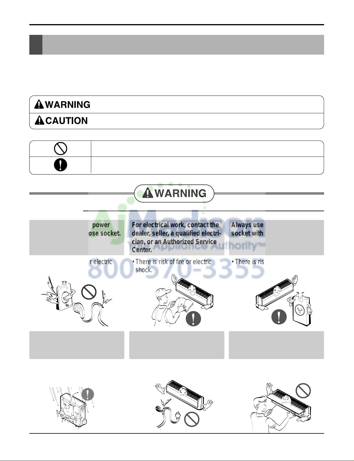
Safety Precautions
Safety Precautions
To prevent injury to the user or other people and property damage, the following instructions must
be followed.
■ Incorrect operation due to ignoring instruction will cause harm or damage. The seriousness is
classified by the following indications.
■ Meanings of symbols used in this manual are as shown below.
This symbol indicates the possibility of death or serious injury.
This symbol indicates the possibility of injury or damage to properties only.
Be sure not to do.
Be sure to follow the instruction.
■ Installation
Do not use damaged power
cords, plugs, or a loose socket.
• There is risk of fire or electric
shock.
For electrical work, contact the
dealer, seller, a qualified electri-
cian, or an Authorized Service
Center.
• There is risk of fire or electric
shock.
Always use the power plug and
socket with the ground terminal.
• There is risk of electric shock.
Install the panel and the cover of
control box securely.
• There is risk of fire or electric
shock.
Do not modify or extend the
power cord.
• There is risk of fire or electric
shock.
Do not install, remove, or reinstall the unit by yourself (customer).
• There is risk of fire, electric
shock, explosion or injury.
4 Room Air Conditioner
Safety Precautions
■ Operation
Be cautious when unpacking
and installing the product.
• Shape edges could cause injury.
Be especially careful of the sharp
edges.
For installation, always contact
the dealer or an Authorized
Service Center.
• There is risk of fire, electric
shock, explosion, or injury.
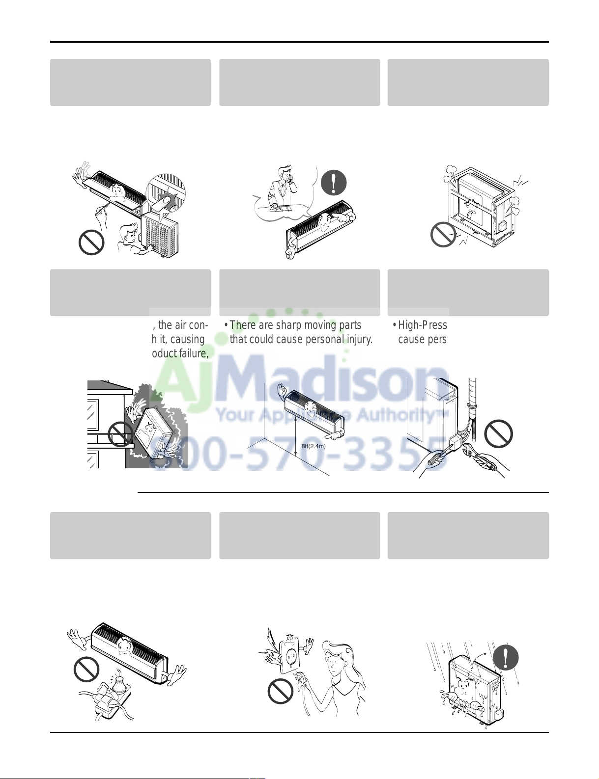
Do not install the product on a
defective installation stand.
• It may cause injury, accident, or
damage to the product.
Be sure the installation area
does not deteriorate with age.
• If the base collapses, the air con-
ditioner could fall with it, causing
property damage, product failure,
and personal injury.
Install the indoor unit on the
wall where the height from the
floors more then 8ft(2.4m)
• There are sharp moving parts
that could cause personal injury.
Do not handle the pipe by yourself(customer)
• High-Pressure refrigent may
cause personal injury.
Use a dedicated outlet for this
appliance.
• There is risk of fire or electric
shock.
Grasp the plug to remove the
cord from the outlet. Do not
touch it with wet hands.
• There is risk of fire or electric
shock.
Do not allow water to run into
electric part.
• There is risk of fire, failure of the
product, and/or electric shock.
8ft(2.4m)
Service Manual 5
Safety Precautions
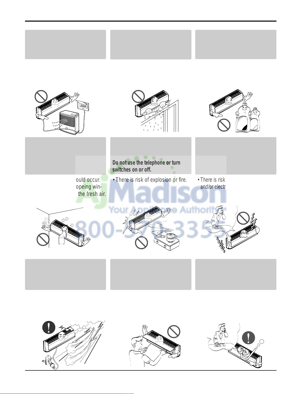
Do not place a heater or other
appliances near the power
cable.
•
There is risk of fire, failure of the
product, and/or electric shock.
Do not let the air conditioner run
for a long time when the humidity is very high and a door or a
window is left open.
• Moisture may condense and wet
or damage furnishings.
Do not store of use flammable
gas or combustibles near the air
conditioner.
• There is risk of fire or product failure.
Do not use the product in a
tightly closed space for a long
time.
• Oxygen deficiency could occur.
• Some ventilation by opeing win-
dow is necessary for the fresh air.
When flammable gas leaks, turn off
the gas and open a window for ventilation before turning the product on.
Do not use the telephone or turn
switches on or off.
• There is risk of explosion or fire.
Unplug the unit if strange
sounds odors or smoke comes
from it.
•
There is risk of fireproduct failure
and/or electric shock.
Stop operation and close any
window in storm or hurricane.
before the hurricane arrives.
• There is risk of property damage,
failure of product, or electric
shock.
Do not open the inlet grill of the
product during operation. (Do
not touch the electrostatic filter,
if the unit is so equipped.)
• There is risk of physical injury,
electric shock, or product.
When the product is soaked
(flooded or submerged), contact
an Authorized Service Center.
• There is risk of electrical shock.
Thinner
Wax
6 Room Air Conditioner
Safety Precautions
Ventilate the product from time
to time when operating it together with a stove, etc.
• There is risk of fire or electrical
shock.
Unplug the appliance before
performing cleaning or maintenance.
• There is risk of electric shock.
When the product is not be used
for a long time disconnect the
power supply plug or turn off
the breaker.
• There is risk of product damage
or failure, or unintended operation.
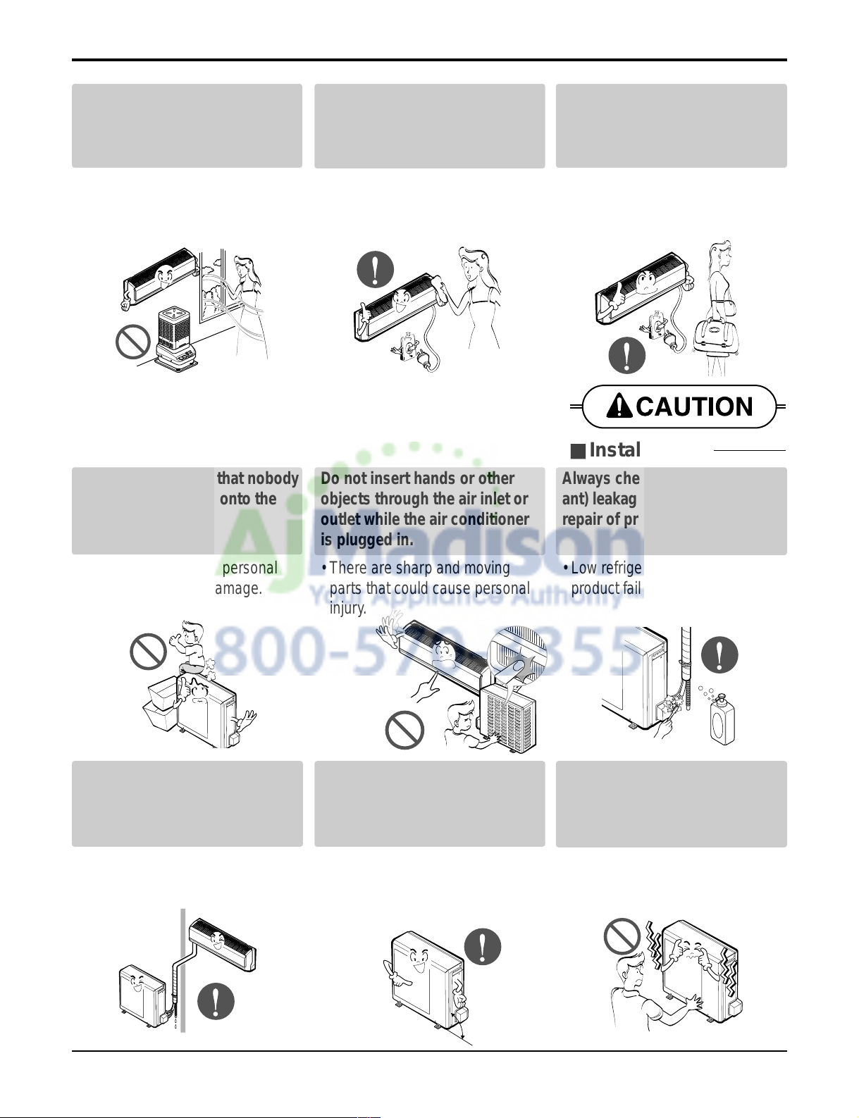
Take care to ensure that nobody
could step on or fall onto the
outdoor unit.
• There could result in personal
injury and product damage.
Do not insert hands or other
objects through the air inlet or
outlet while the air conditioner
is plugged in.
• There are sharp and moving
parts that could cause personal
injury.
Always check for gas(refrigerant) leakage after installation or
repair of product.
• Low refrigerant levels may cause
product failure.
Install the drain hose to ensure
that water is drained away properly.
• A bad connection may cause
water leakage.
Keep level even when installing
the product.
• To avoid vibration or w ater leakage.
Do not install the product where
the noise or hot air from the outdoor unit could damage the
neighborhoods.
• It may cause a problem for your
neighbors.
■ Installation
90˚
Service Manual 7
■ Operation
Safety Precautions
Use two or more people to lift
and transport the air conditioner
• Avoid personal injury.
Do not install the product where
it will be exposed to sea wind
(salt spray) directly.
• It may cause corrosion in the
product. Corrosion, particularly
on the condenser and evaporator
fins, could cause product malfunction or inefficient operation.
Do not direct airflow at room
occupants.
• This could damage your health.
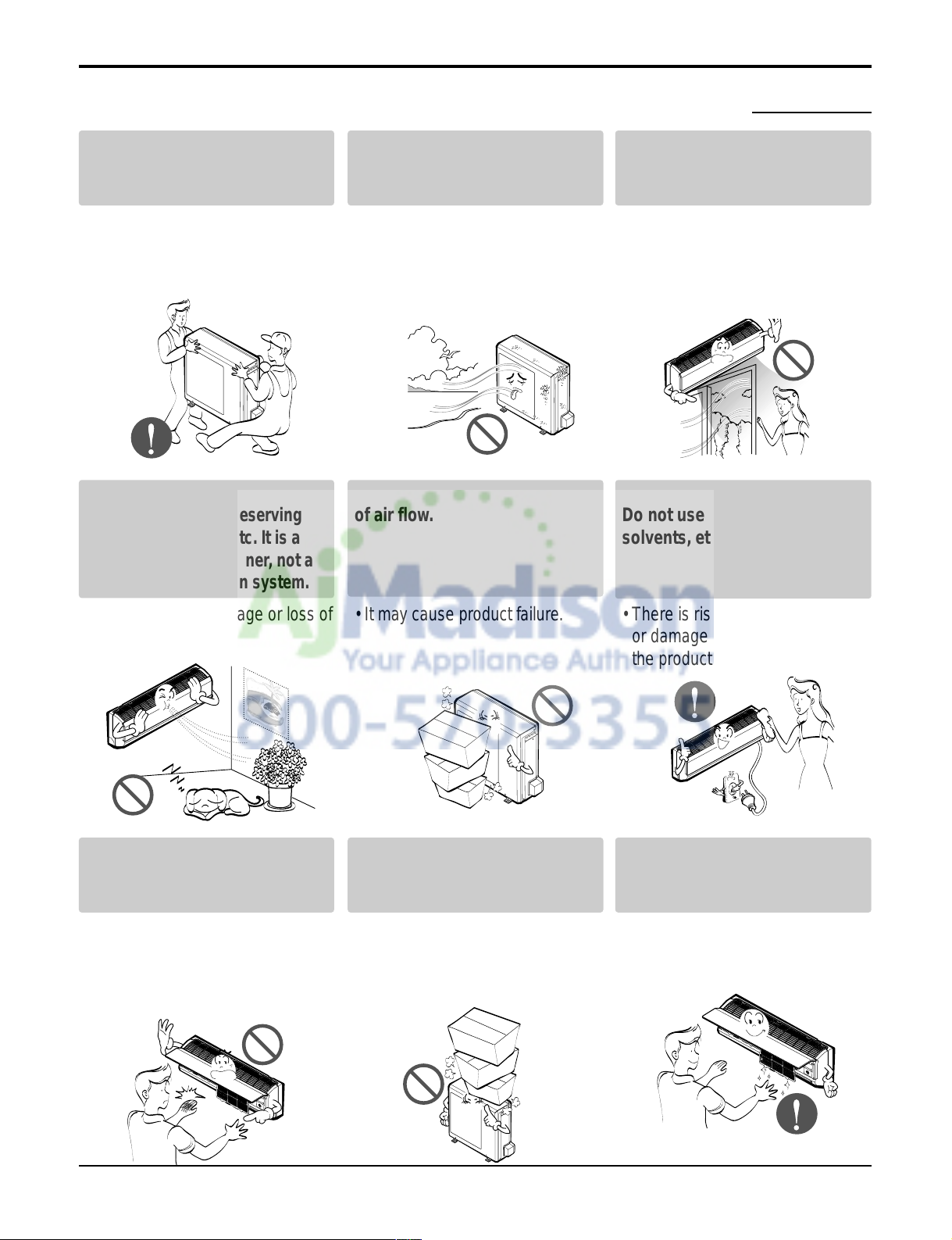
Do not use the product for special
purposes, such as preserving
foods, works of art, etc. It is a
consumer air conditioner, not a
precision refrigeration system.
• There is risk of damage or loss of
property.
Do not block the inlet or outlet
of air flow.
• It may cause product failure.
Use a soft cloth to clean.
Do not use harsh detergents,
solvents, etc.
• There is risk of fire, electric shock
or damage to the plastic parts of
the product.
Do not touch the metal parts of
the product when removing the
air filter. They are very sharp!
• There is risk of personal injury.
Do not step on or put anything
on the product. (outdoor unit)
• There is risk of personal injury
and failure of product.
Always insert the filter securely.
Clean the filter every two weeks
or more often if necessary.
• A dirty filter reduces the efficiency of the air conditioner and
8 Room Air Conditioner
Dimensions
Do not drink the water drained
from the unit.
• It is not sanitary and could cause
serious health issues.
Use a firm stool or ladder when
cleaning or maintaining the air
conditioner.
• Be careful and avoid personal
injury.
Replace all the batteries in the
remote.
• There is risk of fire or explosion.
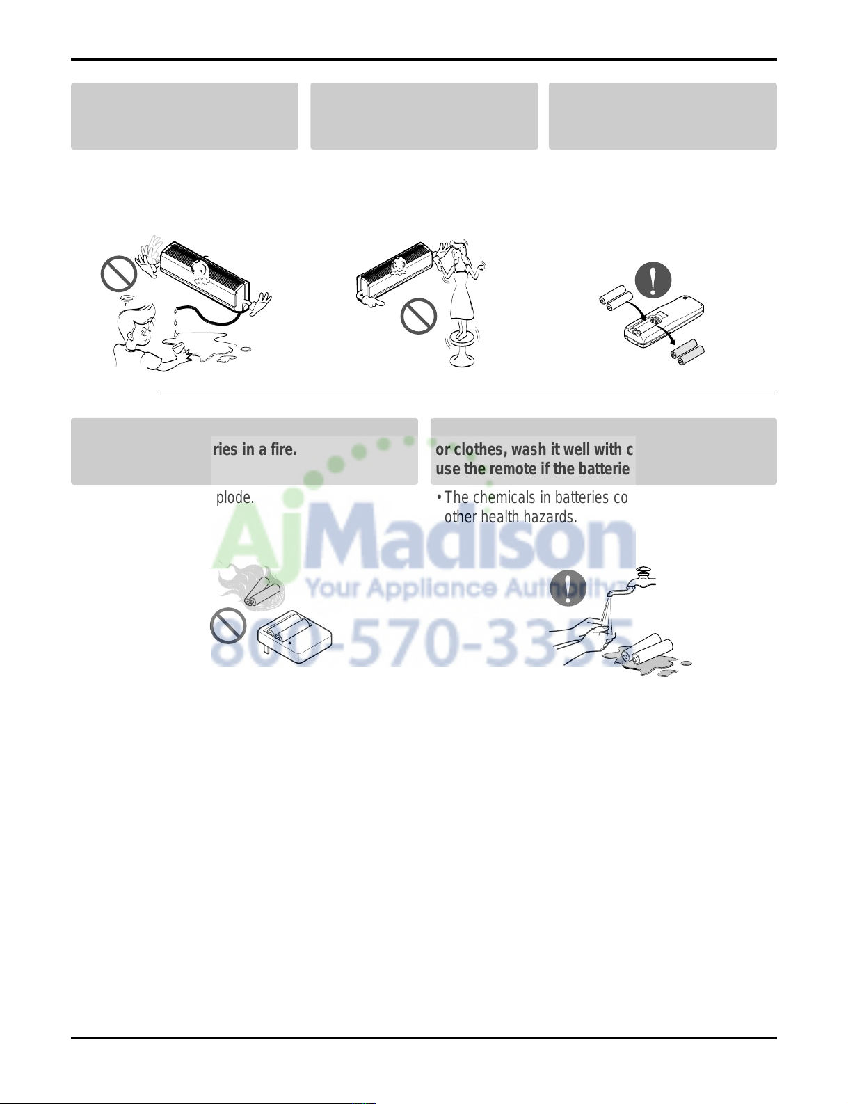
Do not recharge or disassemble the batteries. Do
not dispose of batteries in a fire.
• They may burn or explode.
If the liquid from the batteries gets onto your skin
or clothes, wash it well with clean water. Do not
use the remote if the batteries have leaked.
• The chemicals in batteries could cause burns or
other health hazards.
■ Disuse
Service Manual 9
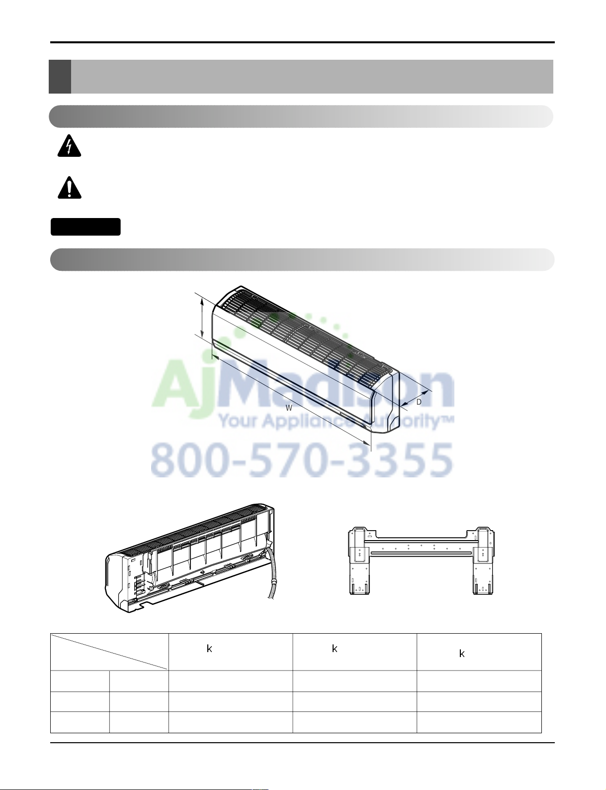
Dimensions
Dimensions
D
H
W
Installation plate
W mm(inch) 840(33.1) 894(35.2) 894(35.2)
H mm(inch) 270(10.6) 295(11.6) 295(11.6)
D mm(inch) 153(6.0) 165(6.5) 165(6.5)
Model
Dimension
9 Btu Series
(C/O)
9 Btu Series
(H/P)
12
Btu Series
Indoor Unit
This symbol alerts you to the risk of electric shock.
This symbol alerts you to hazards that could cause harm to the
air conditioner.
This symbol indicates special notes.
Symbols Used in this Manual
NOTICE
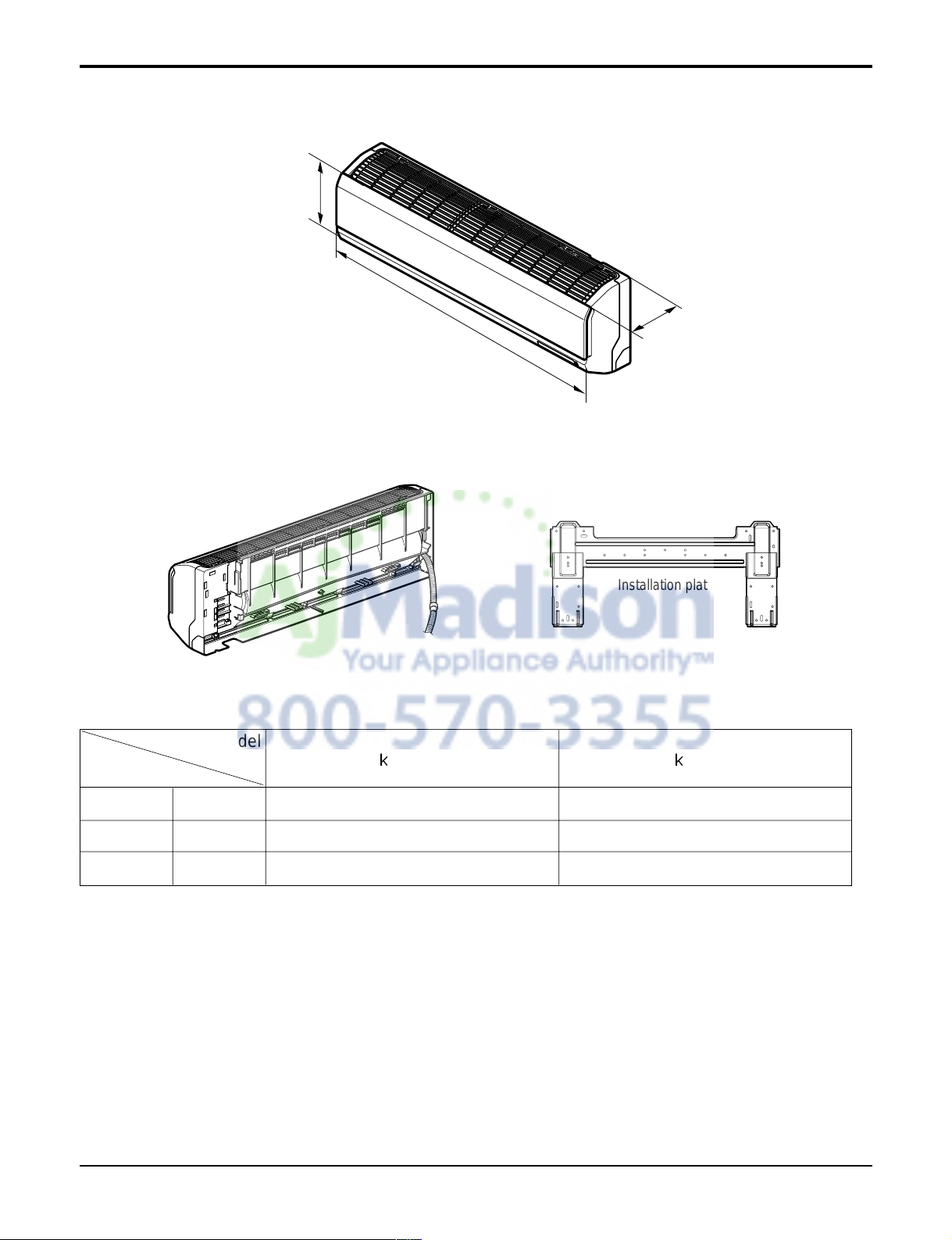
10 Room Air Conditioner
D
H
W
Installation plate
Dimensions
W mm(inch) 1090(42.9) 1090(42.9)
H mm(inch) 300(11.8) 300(11.8)
D mm(inch) 178(7.0) 178(7.0)
Model
Dimension
18 Btu Series 24 Btu Series
Service Manual 11
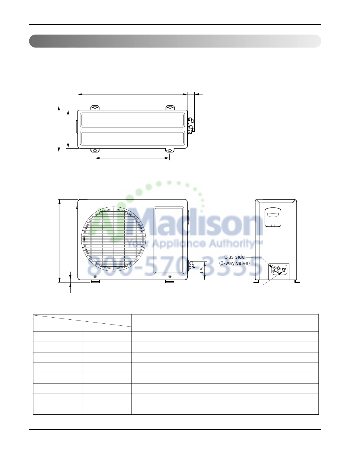
Dimensions
Outdoor Unit
1. 9k, 12k
W
L2
L3
L1
D
H
L4
L5
Gas side
(3-way valve)
Liquid side
(2-way valve)
MODEL
9k, 12k
DIM unit
W mm(inch) 770(30.3)
H mm(inch) 540(21.3)
D mm(inch) 245(9.6)
L1 mm(inch) 287(11.3)
L2 mm(inch) 64(2.5)
L3 mm(inch) 518(20.4)
L4 mm(inch) 10(0.4)
L5 mm(inch) 100(3.9)
12 Room Air Conditioner
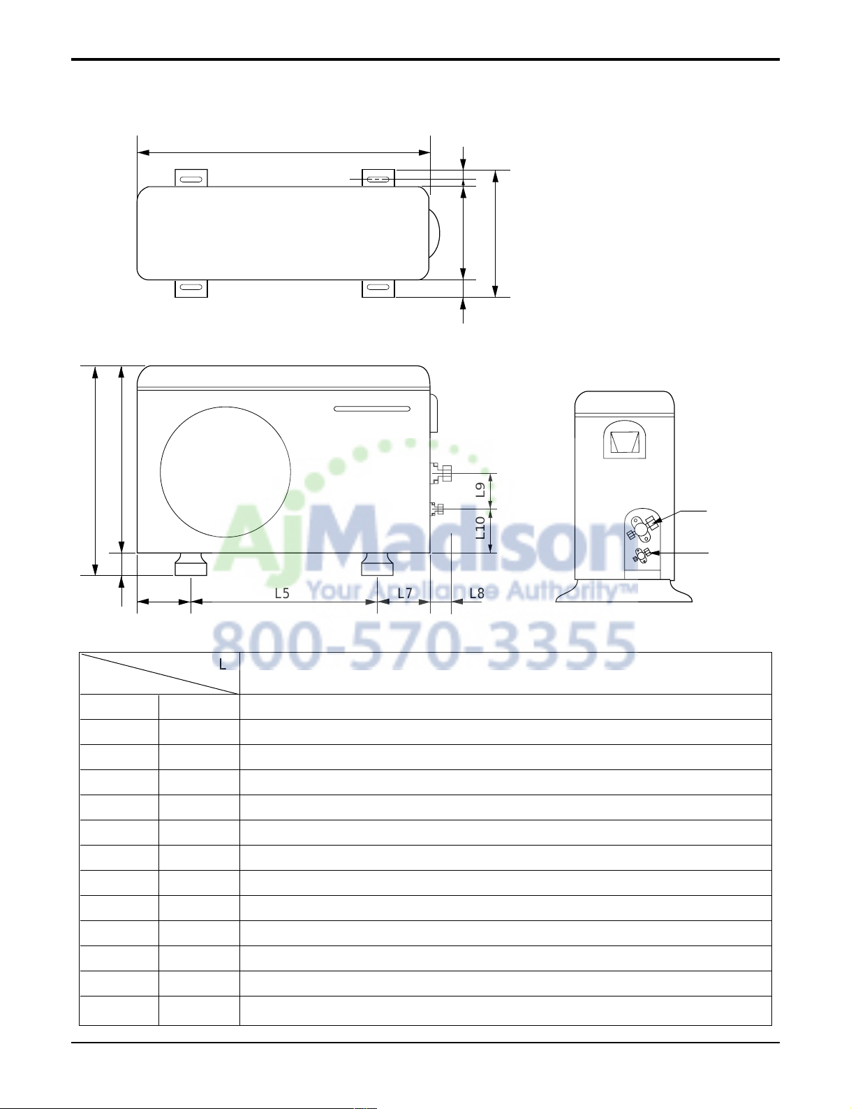
Dimensions
2. 18k, 24k
W
L6 L5 L7 L8
D
L1
L2
L9L10
L3L4
H
MODEL
18k, 24k
DIM
W mm(inch) 870(34.3)
H mm(inch) 655(25.8)
D mm(inch) 320(12.6)
L1 mm(inch) 370(14.6)
L2 mm(inch) 25(1.0)
L3 mm(inch) 630(24.8)
L4 mm(inch) 25(1.0)
L5 mm(inch) 546(21.5)
L6 mm(inch) 162(6.4)
L7 mm(inch) 162(6.4)
L8 mm(inch) 54(2.1)
L9 mm(inch) 74.5(2.9)
L10 mm(inch) 79(3.1)
Service Manual 13
Introduction
Introduction
This symbol alerts you to the risk of electric shock.
This symbol alerts you to hazards that may cause harm to the air conditioner.
This symbol indicates special notes.
Symbols Used In This Manual
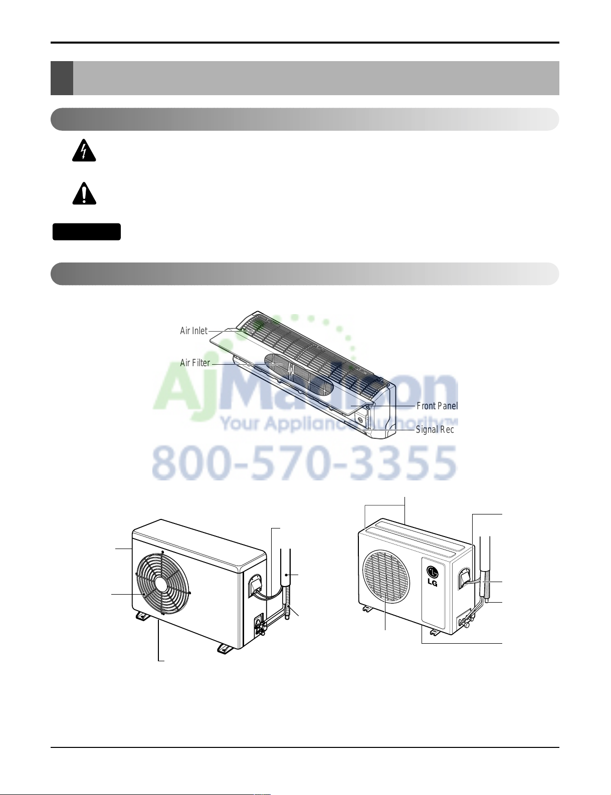
Features
Air Intake Vents
Air Outlet Vents
Connecting
Wires
Piping
Drain Hose
Base Plate
Air Outlet
Vents
Air Intake
Vents
Piping
Connecting
Wires
Drain Hose
Signal Receptor
Base Plate
Front Panel
Air Inlet
Air Filter
NOTICE
14 Room Air Conditioner
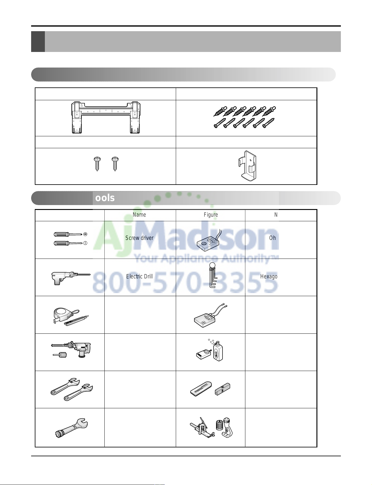
Installation
Type "A" screw and plastic anchor
Type "B" screw
Remote Control Holder
Installation plate
Figure FigureName
Screw driver
Electric Drill
Measuring Tape, Knife
Hole Core Drill
Spanner
Torque wrench
Ohmmeter
Hexagonal wrench
Ammeter
Gas Leak Detector
Thermometer,
Level
Flaring Tool Set
Name
Installation Parts
Installation Tools
Read carefully, and then follow step by step.
Installation
Service Manual 15
Installation
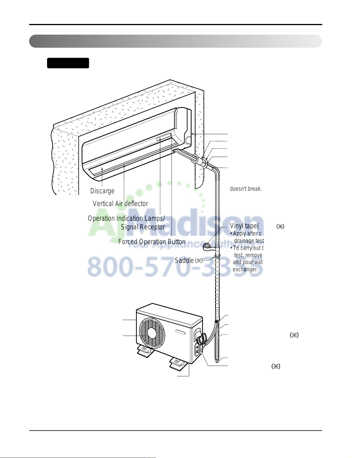
Installation Map
Installation parts you should purchase.
Vertical Air deflector
Air Discarge
Forced Operation Button
Operation Indication Lamps/
Signal Receptor
Vinyl tape(Wide)
• Apply after carrying out a
drainage test.
• To carry out the drainage
test, remove the air filters
and pour water into the heat
exchanger.
Saddle
Gas side piping
Liquid side piping
Additional drain pipe
Drain Hose
Base Plate
Air Inlet Vents
Connecting cable
Installation Plate
Sleeve
Bushing-Sleeve
Putty(Gum Type Sealer)
Bend the pipe as closely
on the wall as possible,
but be careful that it
doesn't break.
NOTICE
NOTE: refrigerant line wall thickness must be at least 0.8 mm (0.031 inch)
Air Outlet Vents
16 Room Air Conditioner
1. Check the quality label on the indoor and outdoor unit.
2. Make certain that the refrigerant is R-410A.
THIS PRODUCT CONTAINS R-410A REFRIGERANT
1) Different compressor oil
- R-410A(Polyol ester) / R-22(Mineral).
- Do not mix the existing mineral oil.
- Do not apply used pipe, tools and gauges covered with the existing mineral oil.
2) Absorption of moisture
-Compressor’s oil has the high absorption rate of moisture.
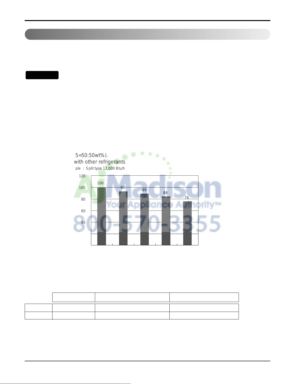
3) Composition
- R-410A(R32:R125=50:50wt%).
NOTE: Never mix with other refrigerants
4) High pressure.
- 1.6 times higher than R-22.
- High Pressure refrigerant may cause personal injury.
Do not handle the pipe by yourself (customer) High-pressure refrigerant may cause personal injury.
- manifold gauge ,charging and any piping tools must be dedicated to R-410A systems.
Confirm The Refrigerant
Boiling Pt.(
°C) V apor pressure(25°C)(kg f/cnf) V apor density(25°C)(kg/m
2
)
R-410A -51.4 15.9 64
R-22 -40.8 9.6 44.4
NOTICE
Example : Split type 12,000 Btu/h
120
100
100
80
93
89
84
76
60
40
20
0
R-410A
R-22
100%
70% 50% 30%
0%
100%70%50%30%0%
Service Manual 17
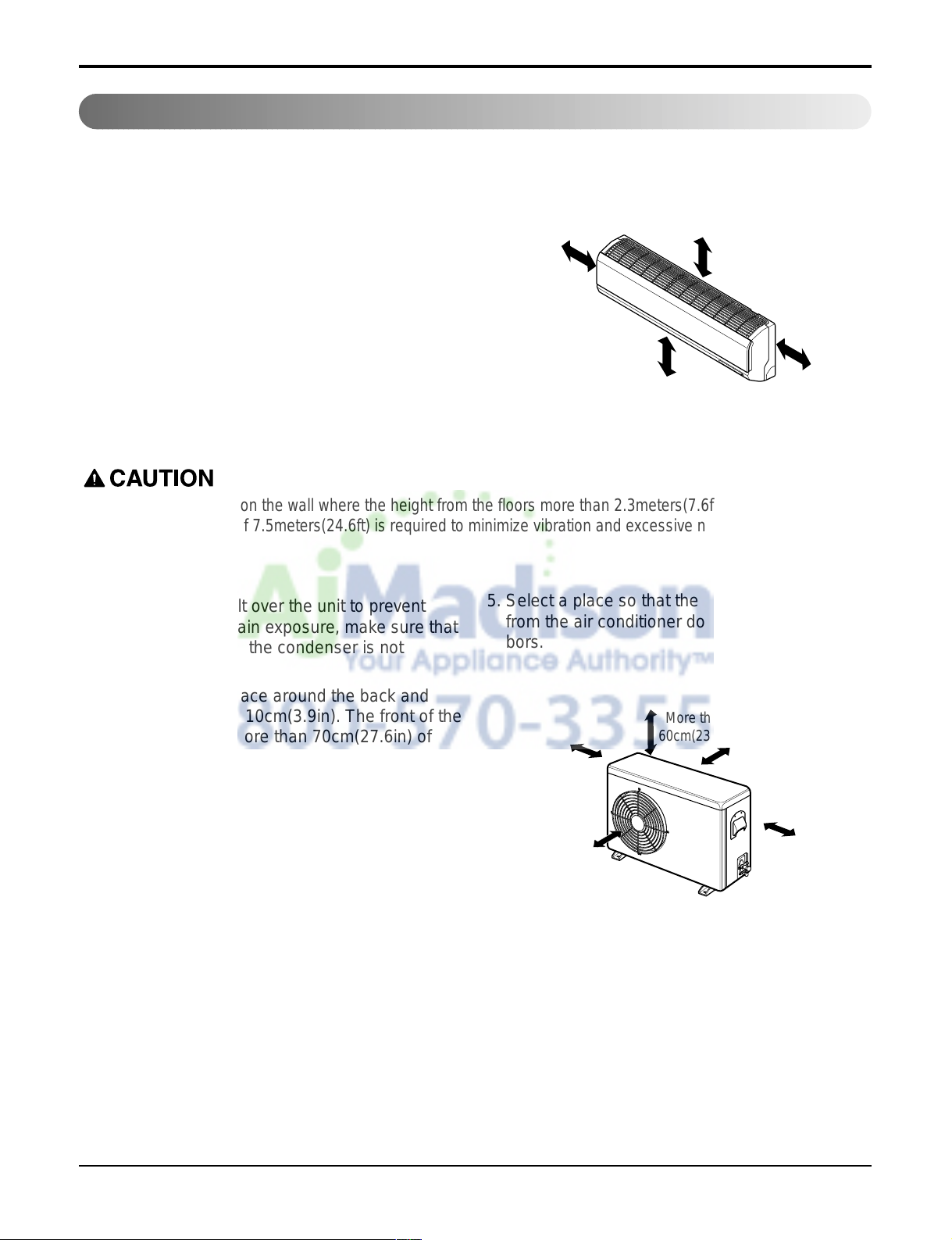
Outdoor unit
1. If an awning is built over the unit to prevent
direct sunlight or rain exposure, make sure that
heat radiation from the condenser is not
restricted.
2. Ensure that the space around the back and
sides is more than 10cm(3.9in). The front of the
unit should have more than 70cm(27.6in) of
space.
3. Do not place animals and plants in the path of
the warm air.
4. Take the air conditioner weight into account and
select a place where noise and vibration are
minimum.
5. Select a place so that the warm air and noise
from the air conditioner do not disturb neighbors.
Rooftop Installations
If the outdoor unit is installed on a roof structure, be sure to level the unit. Ensure the roof structure and
anchoring method are adequate for the unit location. Consult local codes regarding rooftop mounting.
If the outdoor unit is installed on roof structures or walls, this may result in excessive noise and vibration, and may be also classed as non serviceable installation.
Indoor unit
1. Do not have any heat or steam near the unit.
2. Select a place where there are no obstacles in
front of the unit.
3. Make sure that condensation drainage can be
conveniently routed away.
4. Do not install near a doorway.
5. Ensure that the space around the left and right
of the unit is more than 30cm(11.8in). The unit
should be installed as high on the wall as possible, allowing a minimum of 12cm(4.7in) from
ceiling.
6. Use a stud finder to locate studs to prevent
unnecessary damage to the wall.
Select The Best Location
Install the indoor unit on the wall where the height from the floors more than 2.3meters(7.6ft).
A minimum pipe run of 7.5meters(24.6ft) is required to minimize vibration and excessive noise.
More than
12cm(4.7in)
More than
30cm(11.8in)
More than
30cm(11.8in)
More than 8ft(2.4m)
More than
10cm(3.9in)
More than
10cm(3.9in)
More than
60cm(23.6in)
More than
60cm(23.6in)
More than
70cm(27.6in)
18 Room Air Conditioner
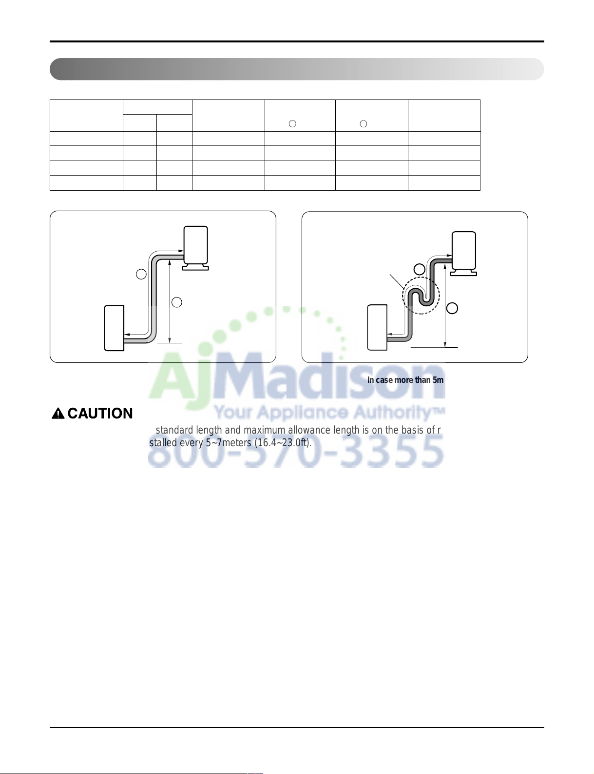
Piping Length And Elevation
• Capacity is based on standard length and maximum allowance length is on the basis of reliability.
• Oil trap should be installed every 5~7meters (16.4~23.0ft).
Pipe Size
Capacity
(Btu/h)
Suction
Evap
Max.
length
A m(ft)
Additional Refrigerant
g/m(oz/ft)
Max.
Elevation
B m(ft)
Standard
Length
m(ft)
In case more than 5m(16.4ft)
Outdoor unit
Indoor unit
A
B
A
Oil trap
Outdoor unit
Indoor unit
B
9k(C/O) 3/8" 1/4" 7.5(25) 7.5(25) 15(49) 20(0.22)
9k(H/P), 12k 1/2" 1/4" 7.5(25) 7.5(25) 15(49) 20(0.22)
18k(C/O) 1/2" 1/4" 7.5(25) 15(49) 30(98) 20(0.22)
18k(H/P), 24k 5/8" 1/4" 7.5(25) 15(49) 30(98) 30(0.32)
Service Manual 19
The wall you select should be strong and solid enough
to prevent vibration
1. Mount the installation plate on the wall with
type "A" screws. If mounting the unit on a concrete
wall, use anchor bolts.
• Mount the installation plate horizontally by aligning the
centerline using a level.
How To Mount Installation Plate
Chassis
Hook
Installation Plate
Type “A”
• Drill the piping hole with a ø70mm(2.76in) hole
core drill. Drill the piping hole at either the right
or the left with the hole slightly slanted to the outdoor side.
Drill a Hole In The Wall
5-7mm
(0.2~0.3")
Indoor
WALL
Outdoor
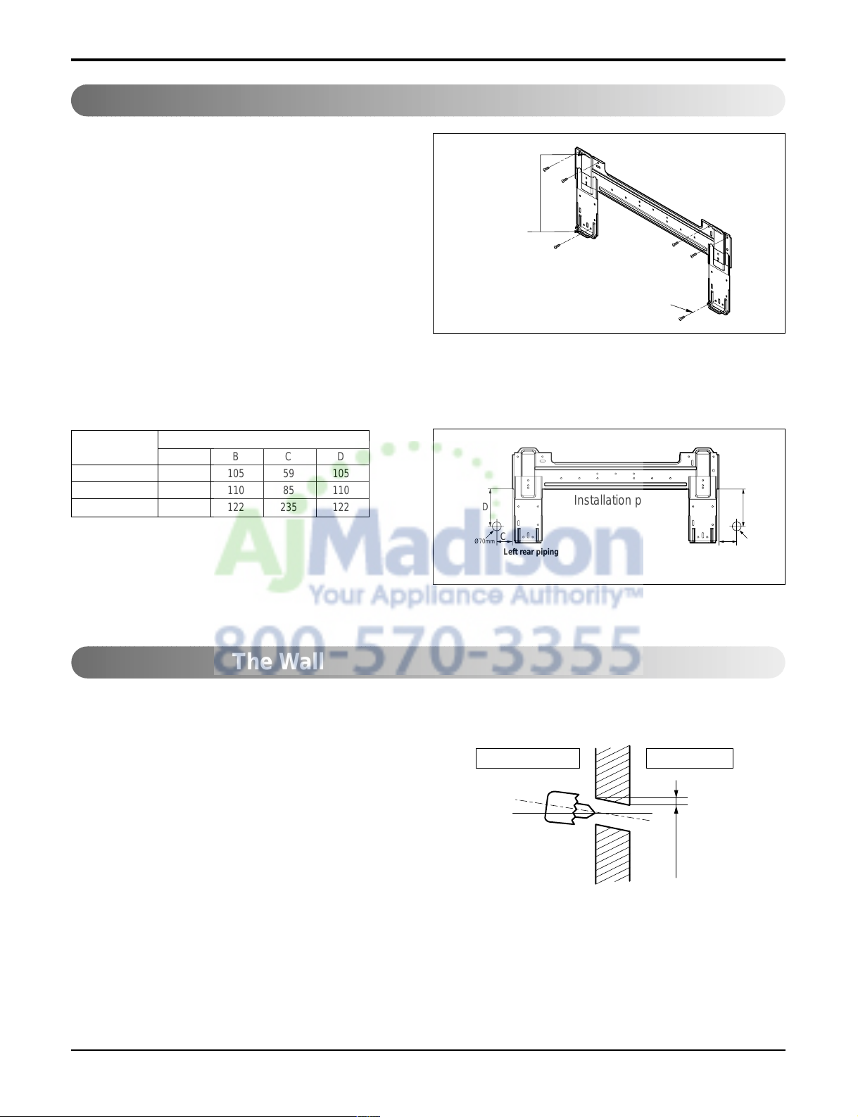
2. Measure the wall and mark the centerline. It is also important to use caution concerning the location of the installation plate-routing of the wiring to power outlets is through the walls typically. Drilling the hole through the wall
for piping connections must be done safely.
Installation plate
Left rear piping Right rear piping
Ø70mm
Ø70mm
D
B
A
C
ABCD
S4 50 105 59 105
SE 65 110 85 110
S5 95 122 235 122
CHASSIS
(Grade)
Distance (mm)
20 Room Air Conditioner
Flaring Work
Cut the pipes and the cable.
1. Use the piping kit accessory or the pipes purchased
locally.
2. Measure the distance between the indoor and the outdoor unit.
3. Cut the pipes a little longer than measured distance.
4. Cut the cable 1.5m(59.1in) longer than the pipe length.
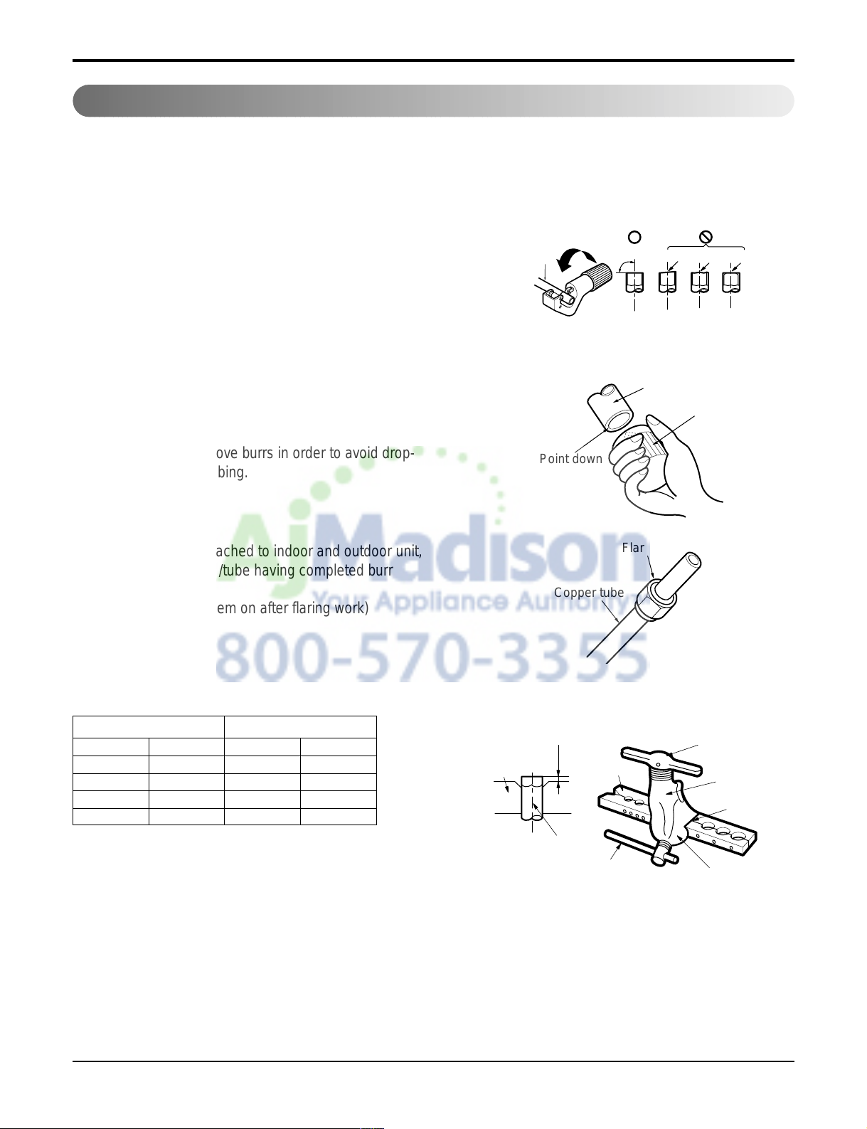
Burrs removal
1. Completely remove all burrs from the cut cross section
of pipe/tube.
2. Put the end of the copper tube/pipe in a downward
direction as you remove burrs in order to avoid drop-
ping burrs into the tubing.
Putting nut on
• Remove flare nuts attached to indoor and outdoor unit,
then put them on pipe/tube having completed burr
removal.
(not possible to put them on after flaring work)
Flaring work
• Carry out flaring work using flaring tool as shown below.
Main cause for gas leakage is due to defect in flaring work. Carry out correct flaring work in the following procedure.
mm inch mm inch
Ø6.35 1/4 0~0.5 0~0.020
Ø9.52 3/8 0~0.5 0~0.020
Ø12.7 1/2 0~0.5 0~0.020
Ø15.88 5/8 0~1.0 0~0.039
Outside diameter A
Bar
Copper pipe
Clamp handle
Red arrow mark
Cone
Yoke
Handle
Bar
"A"
Pipe
Reamer
Point down
Copper
pipe
90°
Slanted Uneven Rough
Firmly hold copper pipe in a die in the dimension shown in the table abov e .
Flare nut
Copper tube
Service Manual 21
Indoor
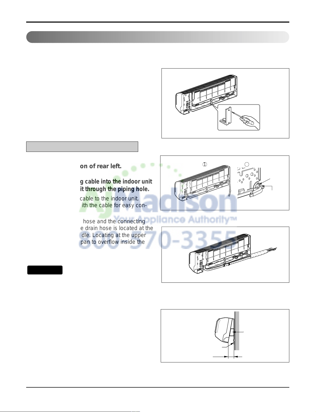
1. Prepare the indoor unit's piping and drain hose for installation through the wall.
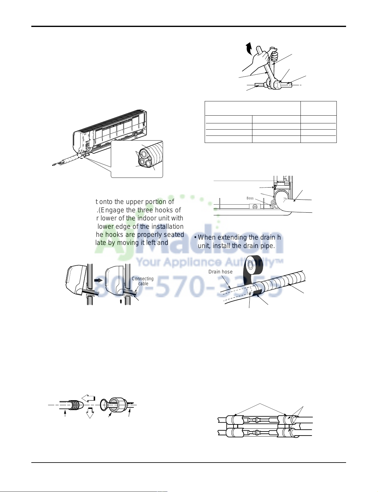
2. Remove the plastic tubing retainer(see the illustration by) and pull the tubing and drain hose
away from chassis.
3. Replace only the plastic tubing holder 1, not the
holder 2 in the original position.
Route the indoor tubing and the drain
hose in the direction of rear left.
Insert the connecting cable into the indoor unit
from the outdoor unit through the piping hole.
• Do not connect the cable to the indoor unit.
• Make a small loop with the cable for easy con-
nection later.
Tape the tubing, drain hose and the connecting
cable. Be sure that the drain hose is located at the
lowest side of the bundle. Locating at the upper
side can cause drain pan to overflow inside the
unit.
If the drain hose is routed inside the room, insulate the hose with an insulation material* so that
dripping from "sweating"(condensation) will not
damage furniture or floors.
*Foamed polyethylene or equivalent is recom-
mended.
Indoor unit installation
• Hook the indoor unit onto the upper portion of
the installation plate.(Engage the three hooks of
the rear top and rear lower of the indoor unit with
the upper edge and lower edge of the installation
plate.) Ensure that the hooks are properly seated
on the installation plate by moving it left and
right.
Connecting The Piping
For left rear piping
NOTICE
1 2
Connecting
cable
Drain pipe
Indoor unit
Spacer
Installation plate
8cm
22 Room Air Conditioner
Wrap the insulation material around the
connecting portion.
• Overlap the connection pipe insulation material
and the indoor unit pipe insulation material. Bind
them together with vinyl tape so that there is no
gap.
Route the indoor tubing and the drain
hose to the required piping hole position.
Plastic bands
Insulation material
Connection pipe
Flare nut
Indoor unit tubing
Torque wrench
Spanner (fixed)
Vinyl tape(narrow)
Adhesive
Drain pipe
Indoor unit drain hose
• When extending the drain hose at the indoor
unit, install the drain pipe.
• Tighten the flare nut with a wrench.
For right rear piping
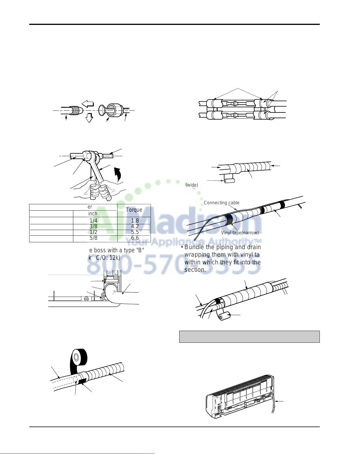
Connecting the pipings to the indoor unit
and drain hose to drain pipe.
• Put a couple drops of refrigerant oil on the face
of the flare before assembling taking care not to
add any contaminants.
• Align the center of the pipings and sufficiently
tighten the flare nut by hand.
Indoor unit tubing Flare nut Pipings
Drain hose
Ø6.35 1/4 1.8
Ø9.52 3/8 4.2
Ø12.7 1/2 5.5
Ø15.88 5/8 6.6
Outside diameter
mm inch
Torque
Vinyl tape(narrow)
Connection
pipe
Connecting cable
Vinyl tape
(wide)
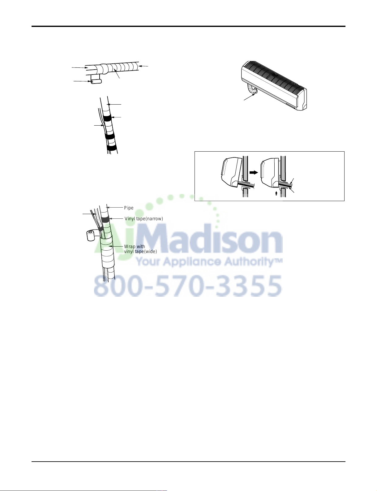
Wrap with vinyl tape
Indoor
unit pipe
Pipe
• Bundle the piping and drain hose together by
wrapping them with vinyl tape over the range
within which they fit into the rear piping housing
section.
Wrap with vinyl tape
Drain hose
Pipe
Vinyl tape(wide)
• Wrap the area which accommodates the rear piping
housing section with vinyl tape.
• Mount the clamp on the boss with a type "B"
screw.(SE-H/P: 9k, 12k C/O: 12k)
Type "B" screw
Clamp
Boss
Drain hose
Service Manual 23
Insert the connecting cable into the indoor
unit.
• Don't connect the cable to the indoor unit.
• Make a small loop with the cable for easy con-
nection later.
Tape the drain hose and the connecting cable.
• Connecting cable
Connecting the pipings to the indoor unit
and the drain hose to drain pipe.
• Put a couple drops of refrigerant oil on the face
of the flare before assembling taking care not to
add any contaminants
• Align the center of the pipings and sufficiently
tighten the flare nut by hand.
• Tighten the flare nut with a wrench.
Indoor unit tubing Flare nut Pipings
Torque wrench
Indoor unit tubing
Spanner (fixed)
Connection pipe
Flare nut
Indoor unit installation
• Hook the indoor unit onto the upper portion of
the installation plate.(Engage the three hooks of
the rear top and rear lower of the indoor unit with
the upper edge and lower edge of the installation
plate.) Ensure that the hooks are properly seated
on the installation plate by moving it left and
right.
Vinyl tape
Adhesive
Drain hose
Indoor unit drain hose
(narrow)
• When extending the drain hose at the indoor
unit, install the drain pipe.
Connecting
pipe
Connecting cable
Tape
Drain hose
Drain hose
Connecting
cable
Ø6.35 1/4 1.8
Ø9.52 3/8 4.2
Ø12.7 1/2 5.5
Ø15.88 5/8 6.6
Outside diameter Torque
• Mount the clamp on the boss with a type "B"
screw.(SE-H/P: 9k, 12k C/O: 12k)
Wrap the insulation material around the
connecting portion.
• Overlap the connection pipe heat insulation and
the indoor unit pipe heat insulation material.
Bind them together with vinyl tape so that there
is no gap.
Plastic bands
Insulation material
Type "B" screw
Clamp
Boss
Drain hose
24 Room Air Conditioner
Reroute the pipings and the drain hose
across the back of the chassis.
Reroute the pipings and the drain hose
across the back of the chassis.
Drain hose
Vinyl tape(narrow)
Pipe
Wrap with
vinyl tape(wide)
• Bundle the piping and drain hose together by
wrapping them with cloth tape over the range
within which they fit into the rear piping housing
section.
Piping for
passage through
piping hole
Drain hose
Connecting
cable
• Wrap the area which accommodates the rear
piping housing section with vinyl tape.
Vinyl tape(narrow)
Connection
pipe
Connecting cable
Indoor
unit piping
Pipe
Vinyl tape
(wide)
Wrap with vinyl tape
Service Manual 25
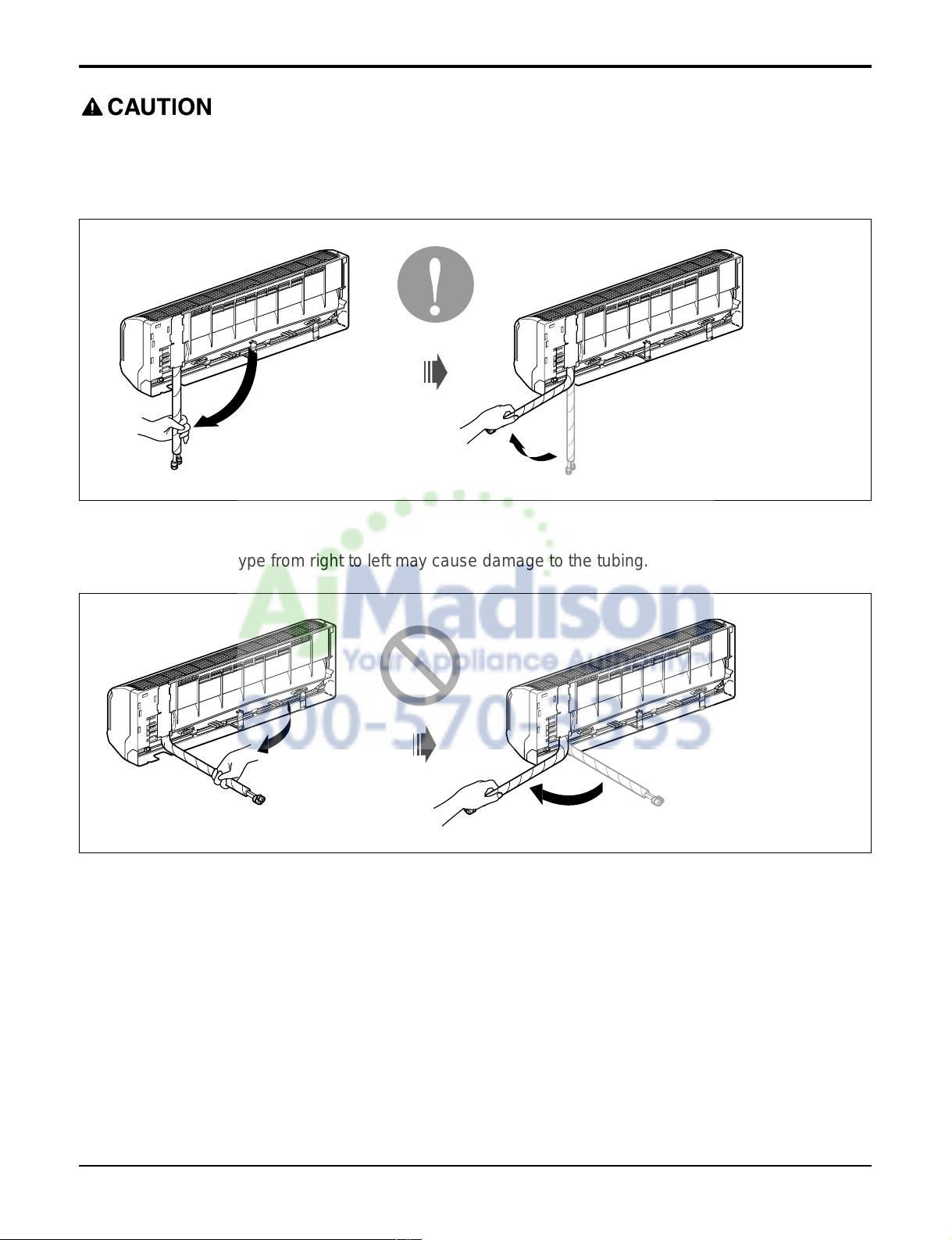
Installation Information. For left piping. Follow the instruction below.
Correct case
• Press on the upper side of clamp and unfold the tubing to downward slowly.
Incorrect case
• Following bending type from right to left may cause damage to the tubing.
 Loading...