


LST-280T USER GUIDE
Please read this manual carefully before operating your
set. Retain it for future reference.

3
TEBLE OF CONTENTS
2
1.1 Safety Instruction
WARNING/CAUTION
To reduce the risk of fire or electric shock, do not
expose this product to rain or moisture. Do not use
this product near swimming pools or other water
bodies.
IMPORTANT
Before installing or operating this product read this
information.
1.2 Optimal Phone Performance
▶
Do not operate your product when holding the
antenna, or when someone is within four inches
(ten centimeters) of the antenna. Holding the
antenna affects call quality and may cause the
telephone to operate at a higher power level than
needed.
▶
For the best call quality, keep the antenna free from
obstructions and position the antenna straight up.
▶
Do not use the phone with a damaged antenna.
Have your antenna replaced by a qualified
technician immediately. Use only the Authorized
LGE Service Center-approved antenna. Non-
approved antennas, modifications, or attachments
could impair call quality, damage the phone.
▶
RF energy may affect improperly installed or
inadequately shielded personal medical devices
such as pace makers, hospital monitor. Consult the
manufacturer of any personal medical devices to
determine if they are adequately shielded from
external RF energy. Turn your terminal OFF in
health care facilities when any regulations posted in
the areas instruct you to do so.
Hospitals or health care facilities may be using
equipment that could be sensitive to external RF
energy.
▶
If this equipment does cause harmful interference
to radio or television reception, which can be
determined by turning the equipment off and on,
the user is encouraged to try to correct the
interference by one or more of the following
measures:
- Reorient or relocate the receiving antenna.
- Increase the distance between the radio or
television and the telephone.
- Connect the equipment into an outlet on a circuit
different from that to which the terminal is
connected.
- Consult your experienced radio/TV technician of
Before You Start 3
1.1 Safety Instruction 3
1.2 Optimal Phone Performance 3
1.3 Care and Service 4
1.4 Safety Information 5
Introduction 8
2.1 Component List 9
2.2 Front, Side and Rear View of the Terminal 10
2.3 3 LEDs Indicators 12
2.4 Installation 13
2.5 Installation Steps 16
Basic Operation 17
3.1 Power On 17
3.2 Placing a Call 17
3.3 Receiving a Call 18
3.4 Ending a Call 18
3.5 Warning Tone after Remote Disconnect 18
3.6 Emergency Call 18
3.7 Power Off 18
System Features 19
4.1 Hook Flash 19
4.2 ROH (Receiver Off Hook) 19
4.3 System Features 19
4.4 Applications 20
Programming 21
5.1 Speed Dial 21
5.2 Emergency Call 22
5.3 Hot Line 23
5.4 Alarm 24
5.5 Volume Level 25
5.6 Outgoing Call Lock 26
5.7 Restrict Call Mode Setting 27
5.8 Auto Dial Time 29
Troubleshooting 30
General Information 31
Limited warranty statement 33
FCC RF Exposure Information 36
LGE Service Center List 37
Before You Start
Before You StartTable of Contents

Before You Start
5
Before You Start
4
1.4 Safety Information
WWAARRNNIINNGG
▶
Do not use harsh chemicals,
cleaning solvents, or strong
detergents to clean it. Wipe it
with a soft cloth that has been
slightly dampened in a mild soapand water solution.
▶
Do not paint it. Paint can clog the
device’s moving parts and
prevent proper operation.
▶
During lightning, do not touch
power plug or phone line. It may
cause an electric shock or death.
CC AAUU TTIIOONN
▶
Do not use with car battery. It
may cause an electric shock, fire,
breakdown or transformation.
▶
For safety use, use only adapter
approved by LG.
To all problems arising from not
following this guide, LG does
not bear responsibility.
▶
Avoid exposure to high
temperature or humidity.
Avoid wetting the unit with any
liquids. If the unit gets wet, turn
the power off immediately and
remove the backup battery and
AC power supply.
▶
Keep it dry. Precipitation,
humidity, and liquids contain
minerals that may corrode
electronic circuits.
▶
Do not use or store it in dusty,
dirty areas as its moving parts
can be damaged.
▶
Do not store it in hot areas.
High temperatures can shorten
the life of electronic devices,
damage batteries, and warp or
melt certain plastics.
the Authorized LGE Service Center
▶
Use only the battery, antenna and AC power supply
provided by LGE.
Using any other type will invalidate the warranty.
▶
Only authorized personnel should service the
phone and its accessories.
Faulty installation or service can be dangerous and
may invalidate the warranty.
▶
Do not use the phone in designated “no cellular
phone use” area.
Avoid exposure to high temperature or humidity.
▶
Avoid wetting the phone with any liquids. If the
phone gets wet, turn the power off immediately and
remove the backup battery and AC power supply.
If the phone is inoperable, then return to the
service agent for service.
▶
Avoid shock or impact.
▶
We recommend you to charge the backup battery
before initial use. Backup battery may be
discharged during delivery.
▶
This phone complies with part 15 of the FCC Rules.
Operation is subject to the following two
conditions:
- This phone may not cause harmful interference,
and
- This phone must accept any interference
received, including interference that may cause
undesired operation.
1.3 Care and Service
▶
Unplug the telephone from the wall outlet and
remove antenna (or disconnect antenna cable)
before cleaning. Do not use liquid or aerosol
cleaners.
Use a damp cloth for cleaning.
▶
If the phone fails for any reason, do not attempt to
disassemble; contact the Authorized LGE Service
Center for assistance.
▶
If any of the following conditions exist: unplug the
phone at the wall plug, remove battery, and call the
service provider.
- The power supply cord is damaged or frayed.
- Liquid has been spilled into the phone.
- The phone has been exposed to rain or water.
- The phone has been dropped or damaged.
- The phone does not work normally by following
the operating instructions.
Before You Start
Before You Start

Before You Start
7
Before You Start
Before You Start
6
▶
Do not short-circuit. It may start
a fire or may explode causing
injury.
▶
Do not throw and impact
battery. Do not dispose of
batteries by putting them in fire.
It may explode or catch fire by
electrolyte.
▶
When you disconnect the power
cord of any accessory, grasp and
pull the plug, not the cord. It may
cause an adapter breakdown.
Before You Start
▶
Do not store it in cold areas.
When the phone warms up to its
normal operating temperature,
moisture can form inside the
phone, which could damage the
phone’s electronic circuit boards.
▶
Do not attempt to open it. Nonexpert handling of the device
could damage it. Consult your
authorized LGE Service Center
for help. It may be a cause of fire,
electric shock and breakdown.
▶
Do not drop, knock or shake it.
Rough handling can break
internal circuit boards.
▶
Do not install under direct
sunlight or on an uneven surface.
▶
Before using plug, check with
available power voltage.
Inaccurate power voltage may be
a cause of fire.
▶
Do not plug many power cords
in outlet. It may be a cause of
fire or electric shock.
▶
Do not remodel the power cord
or disassemble. If power cord or
plug is impaired, do not use it. It
may be a cause of fire or electric
shock.
▶
Do not install in an ill-ventilated
place. It may be a cause of fire or
breakdown.
▶
Do not touch the plug with wet
hands. When disconnecting the
power cord of any accessory,
grasp and pull the plug, not the
cord. It may be a cause of fire or
electric shock.
▶
Do not put heavy things on the
power cord. Do not bend power
cord too much. It may be a
cause of fire or electric shock.
Introduction
9
Congratulations on your purchase of the LG Fixed
Wireless Terminal that has been designed to operate
on the latest digital mobile communications
technology,
Code Division Multiple Access (CDMA). This CDMA
digital technology has greatly enhanced voice clarity
and can provide various advanced features.
The terminal enables the normal operation and direct
connection of standard telephone equipment into the
cellular network.
The standard unit provides:
▶
A phone jack to plug in the telephone
equipment(RJ-11 Port).
▶
Ring voltage used to ring the telephone connected
to the unit, with a Ringer Equivalence Number of 4.
▶
Data Port for repair(RJ-45 Port).
▶
AC Power supply with barrel plug connector.
▶
Support Dial tone.
▶
Touch tone(DTMF) or Pulse Dialing.
▶
Support Caller ID Telephone(DTMF only, not
Support FSK).
▶
One light (LED) to indicate the status of the unit.
▶
Dipole Antenna.
Some features can not be supported by service
provider’s equipment status.
For instance, the following features may not be
supported:
▶
Speed Dial
▶
Emergency Call
▶
Hot Line Call
▶
Alarm
▶
Outgoing Call Lock
▶
Quick Dial Option with “J”
Other features as determined by your service
provider.
Note:
- Telephones with multiple terminating impedance
should be set for 600ohms.
Introduction
Introduction
8
Introduction
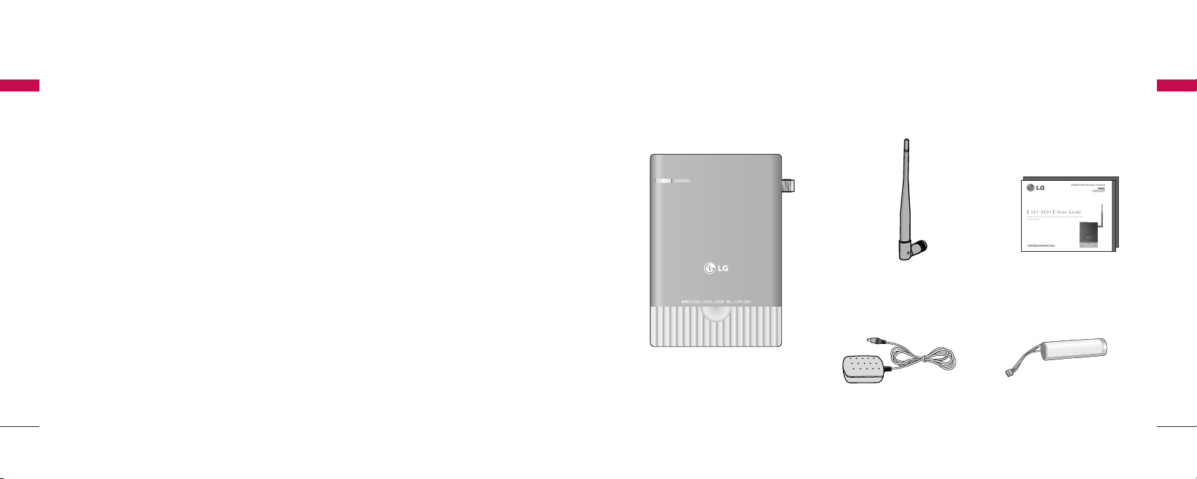
2.1 Component List
< AC/DC Power Adapter >
< Terminal >
< Backup Battery(Built-in) >
< User Guide >
< Dipole Antenna >
10
Introduction
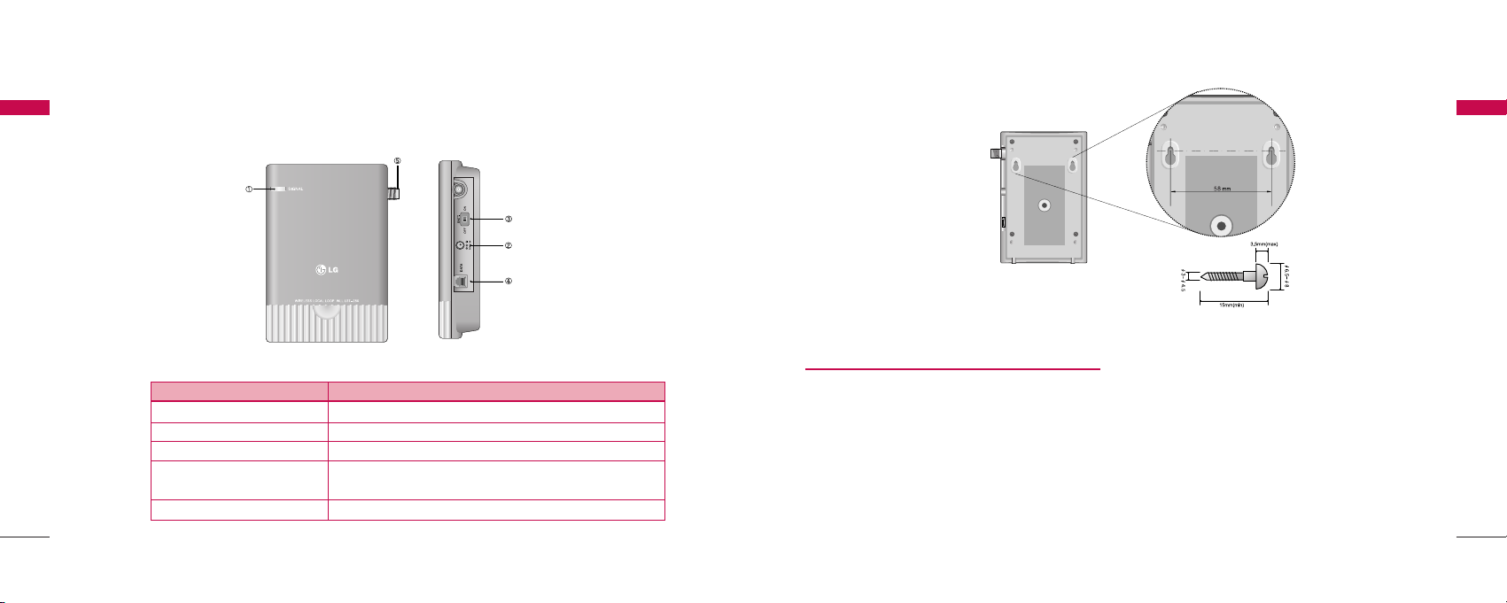
Installation for Wall Mounting
▶
To mount terminal on the wall, please follow the
procedure to install it correctly.
1. Determine suitable location to mount terminal
with mounting template.
2. Mark the two openings and select round or panhead type screw.
3. Drill out the holes with drill bit smaller in
diameter than the screws.
4. Secure two screws into the wall, leaving about
65mm gap between the screw heads.
5. Insert the DC power jack into an electrical outlet
and attach the telephone line into the Phone
Jack (RJ-11) of the terminal.
6. Place the terminal over the two screws.
7. Slide the terminal downward until the screw head
is locked at the top of the opening and the
terminal is secure.
8. Check that set is fixed on the screws.
11
Introduction
Introduction
Introduction
2.2 Front, Side and Rear View of the Terminal
< Figure 1 >
< Mounting Template >
IITTEE MM DDEESSCCRRIIPPTTIIOONN
(1) LED Indicate the status of the unit
(2) DC IN 12V AC/DC Power Adapter
(3) Battery Switch Battery On/Off Switch
(4) TEL (RJ-11 Port) Connecting Ports for SLT
(Single Line Telephone)
(5) Antenna Connector Connecting Port for TNC Antenna
1312
2.4 Installation
You should follow each step carefully as shown below
in order to guarantee proper operation of CDMA
Fixed Wireless Telephone.
STEP I. Check Components
▶
Fixed Wireless Terminal is supplied with the
following standard unit and accessories:
1. LST-280T Unit -1EA-
2. Dipole Antenna -1EA-
3. Backup Battery -1EA-
4. User Guide -1EA-
5. AC/DC Power Adapter -1EA-
▶
Please make sure that these components are
present and check for evidence of shipping before
you begin the unit installation.
▶
If components are missing or damage is found,
contact your authorized LGE Service Center
immediately.
STEP II. Place the Terminal
▶
Place the terminal on the stable flat secure surface
area (desk, table, etc.).
Avoid direct exposure to the sunlight and damp
areas.
▶
Read the SAFETY INFORMATION located at the
first part of this document before you place the
terminal.
STEP III. Connect Components
▶
Connect the Dipole antenna to the TNC connector
located at the topside of the terminal. (See Figure 1
to locate the TNC connector.)
If you have placed the terminal on the flat surface,
position the antenna up side.
▶
Connect your phone cord to the RJ-11 port located
at the side of the terminal.
▶
Connect the battery cable to the DC battery
connector at the side of the terminal.
- Remove the battery compartment cover.
Introduction
Introduction
Introduction
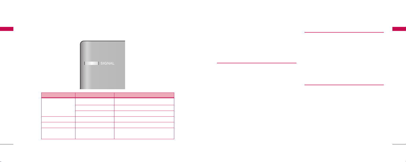
2.3 3 LED Indicators
< Table 1 >
Introduction
IInnffoorrmmaattiioo nn AAcc ttii vviittyy MM ee aann ii nngg
Green Good signal strength
Service Yellow Poor signal strength
Red(Blink) No service Area
PWR (AC/Batt) Red(Solid) Low Battery (Only battery mode)
Mode Green(Blink) Alarm alert, Incoming ringing
Over charger
Red(Fast Blink) Over voltage charger connected
warning
15
- Connect battery to the connector.
- Replace the battery cover.
▶
Connect the AC power supply cable to the DC
input port located at the side of the terminal.
““RR ee ff ee rr ttoo ccoonnnn ee ccttiioonn DDii aagg rraamm wwiitthh
eexxtteerr nnaa ll eeqq uuiippmmeenn tt iinn FFiigg uurree 22 ””
STEP IV. Check LED Indicators
▶
When you followed the installation instruction STEP
I to STEP III, please check the LED for normal
operation.
▶
When DC power is fed at the first time, LED will
operate as follows:
If receiving signal strength is strong enough, then
LED is GREEN.
If not, it is ORANGE solid or RED blinking.
14
Introduction
Introduction
Introduction
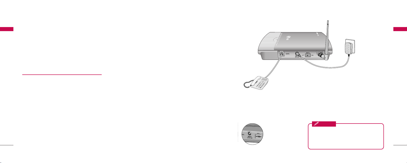
Introduction
< Figure2. Connection Diagram with External Equipment >
LST-280T
Note:
- Length between LST-280T and Telephone : over 1m.
.. TThhee aaddaapptt eerr ttyyppee((wwii tthh ppooww ee rr ccoo rrdd )) mmaayy bbee dd iiffffeerree nntt ffrroomm ccoouunnttrryy ttoo ccoouunn ttrryy..
! Connection telephone jack to data port will cause malfunction of data service
Before using the terminal, please check
battery switch is on.
After switching on it, use the phone. When charging
the battery, check that battery switch is “on”.
Notice
Battery Switch
1716
3.1 Power On
1. The LED indicates the present status:
Using internal battery and battery is weak capacity:
Solid RED
2. When the terminal succeeded in getting the service,
LED indicates the strength of the signal(Table 1).
LL iifftt iinngg hhaa nndd ss ee tt oonn tt ee lleepphhoonnee,, ddiiaall ttoonnee ii ss
hheeaarr dd aanndd yyoouu ccaann eenn tteerr aa pp hhoonnee nnuu mmbb ee rr..
Note:
- Not entering any key for 15 seconds warning
tone will be produced.
- In the overlap dial mode, it may take over
15seconds.
- If Hot Line function is enabled, busy tone is not
produced and hot line number is automatically
connected.
- While having maintenance request order or lock
order from the system, neither dial tone nor busy
tone is produced. Instead of them, the lock
tone(“pi-pi-pi”) will be heard one time and there
will be no sound and LED will blinking with
YELLOW color.
3. If the radio service is not available or radio signal is
too weak to detect:
The LED will blinking with RED color.
(No Service status)
3.2 Placing a Call
When lifting handset of the connected telephone (“off
hook”), the terminal determines whether cellular
service is available.
If it is available, dial tone is produced and a number
can be dialed normally.
If phone service is not available and no dial tone will be
heard.
If user presses “
J
” button after dialed the number,
the terminal makes a call immediately.
Basic Operations
Basic Operations
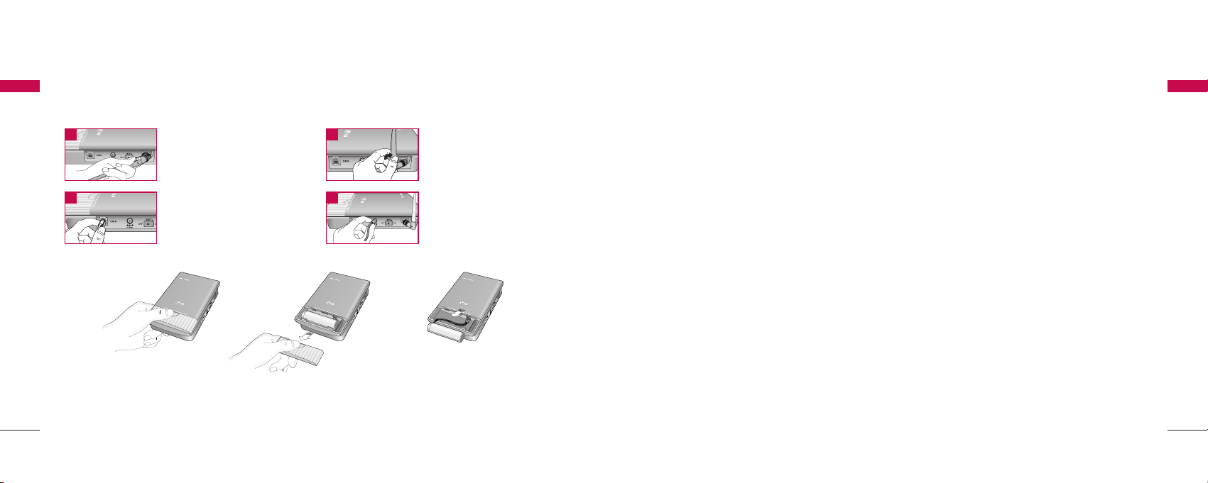
2.5 Installation Steps
Please follow the below procedure to install the unit properly.
Introduction
Introduction
<Terminal Connection >
Connect the antenna
to the TNC connector
Turn right).
Connect your phone
Cord.
Bend the antenna up
right.
Connect the DC
Power supply.
1 2
3 4
<Battery Connection >
▶
First, slow down the terminal slide switch and unscrew.
▶
To connect battery, disassemble terminal like above figure.
▶
Battery connector’s groove must be slid into the jack like above figure.

1918
4.1 Hook Flash
When the terminal receives a hook-flash from the
connected telephone device, it will automatically
allow:
1. For producing dial tone again after a phone
number has been dialed without connection.
2. The use of special cellular services which may be
available in your cellular service area.
Note:
- Hook-flash is accomplished in a call through either
pressing the dedicated hook-flash key which is
available on some phones or through a rapid
single press of the hang-up mechanism upon
which the handset rests when the phone is hung
up.
4.2 ROH (Receiver Off Hook)
If the telephone equipment remains “off-hook”,
meaning that the handset is left off of its cradle as it
would be when you hang up, with no dialing activity
for about 60 seconds, a ROH tone emits from the
receiver for a period of 60 seconds.
This feature may be different or not by country
specification.
4.3 System Features
Many cellular systems offer special services such as
call waiting, call forwarding, etc. You can purchase
these services from your cellular service provider.
There are certain dialing sequences to be earned,
which vary from service provider to service provider.
The service provider will provide the dialing
instructions for your system.
Call Forwarding - An incoming call can be delivered to
another telephone number programmed. Please
contact your cellular service provider to use this
feature.
Call Waiting - You can receive another incoming call
during a call.
In this case, you will hear beep tone and then you can
connect the second call holding the first call by
entering a code required by cellular service provider.
Your cellular service provider may require hook-flash
(a quick, simulated “hang up”) to answer the waiting
System Features
System Features
3.3 Receiving a Call
The connected telephone rings when an incoming call
is detected.
Pick up the handset and begin talking.
3.4 Ending a Call
When you have completed the call, place the handset
back on telephone. Also you can hook flash more than
about 1 second to end a call and place a new call
without hanging up the handset.
3.5 Warning Tone after Remote
Disconnect
A warning tone may be heard in the telephone after a
remote party hangs up from a call, allowing another
call to be initiated after hook-flash.
3.6 Emergency Call
When emergency call number is connected once, it will
not be terminated unless the called party disconnects
the call (Emergency Call Hold Service).
Therefore even caller hangs up the telephone, the line
will be still connected, so if the caller picks up the
telephone again, he can continue talking.
If emergency call is connected, cellular service is not
supported.
As long as your telephone is registered on a system,
you can place a call to emergency number even if your
telephone is locked or restricted.
Please check the available emergency call number with
your service provider.
3.7 Power Off
When you don’t need to use terminal anymore, you
should do power off before removing AC/DC adapter
cable.
If you do terminal power off, Press “#” + “#” + “8” +
“8” + “*” continuously. If so, the terminal will LED off
and stop all operations. Then you shall separate
External Power jack from Terminal.
Basic Operations
Basic Operations

LST-280T provides various convenience and various
features to user. This chapter describes how to
program these features and to use them. The
followings are main features can be used:
-
Speed Dial
-
Emergency Call
-
Hot Line Call
-
Wake-up Alarm
-
Conversation Voice Level
-
Outgoing Call Lock
-
Restrict Call
▶
Programming Instruction
1. Lift Handset and press “#” key twice and you will
hear the Menu Entering tone.
2. Enter the field number (1~ 9).
3. Press “#” key and you will hear confirmation
tone.
4. Enter sub-fields and their options.
5. Press “
J
” key to save and you will hear
confirmation tone.
Note:
- As to the characteristic quality of some telephones,
confirm tone or error tone could not be heard.
5.1 Speed Dial
LST-280T has 30 memory locations (1~30:1 or 2
digits) to store frequently used phone numbers and
you can make a call by pressing memory location
number only when the speed dial feature is enabled.
Storing the Speed Dial Number
1. Press “#” + “#” + “1” continuously to enter
Speed Dial programming mode.
2. Press “#” and one of memory numbers (1~30).
3. Press “#” and the phone number (Max. 32
digits).
4. Press “
J
” to store.
Programming
2120
Programming
call. Other providers may require entering the codes
involving digits 1-9,
J
, and # to answer a waiting call.
Three-way Conference Calls - For three-way
conference calls, a hook-flash transmits the SEND
command.
Please contact your cellular service provider for more
information on using this service.
Example
(1) Dial the first number and wait until connected:
(2) When connected, give hook-flash and dial the
second number and give one more hook-flash to
be connected:
(3) When the second call is connected, give hook
flash to complete a 3-way conference call.
Caller ID - LST-280T can support caller ID service if
you have a telephone with Caller ID feature.
*
During a call, CID is not displayed.
Please contact your cellular service provider for more
information on using this service.
*
Only DTMF Caller ID is Supported, FSK Caller ID is
not Supported.
4.4 Applications
Multi-extension Installations - For a multi-extension
installation, make sure that all the extensions are onhook.
If one extension is off-hook (not hung up), none of the
extensions on that line will ring when a call is being
received.
System Features
System Features

2322
Enable or Disable Emergency Call
1. Press “#”+ “#”+ “2” continuously to enter
Emergency Call programming mode.
2. Press “#” and Enable code (“1”) or Disable code
(“2”).
3. Press “J” to save.
Erase All Emergency Call Numbers
1. Press “#”+ “#”+ “2” continuously to enter
Emergency Call programming mode.
2. Press “#” and “3” to erase all Emergency Call
Numbers.
3. Press “
J
” to store.
Note1: Emergency Call feature is disabled after erase
operation executed
Note :
- If Emergency Call is disabled and Emergency Call
number has been already programmed, you can
make enable Emergency Call by pressing “#”+
“#”+ “2”+ “#”+ “1”+”
J
”without entering a
Emergency Call Number again.
5.3 Hot Line
While the Hot line function is enabled, the
programmed number will be automatically dialed when
you pick up the handset and wait for the programmed
hot line time (2~10sec) without any key press.
Programming the Hot Line Number
1. Press “#”+ “#”+ “3” continuously to enter Hot
Line programming mode.
2. Press “#” and Hot Line Enable code “1”.
3. Press “#”and Hot Line phone number (Max. 32
digits).
4. Press “
J
” to save and enable this function.
Enable the Hot Line Feature
1. Press “#”+ “#”+ “3” continuously to enter Hot
Line programming mode.
2. Press “#” and Hot Line Enable code “1”.
3. Press “
J
” to save.
Programming
Programming
Programming
Programming
Enable or Disable Speed Dial
1. Press “#”+ “#”+ “1” continuously to enter
Speed Dial programming mode.
2. Press “#” and “1” or “2” to Enable or Disable
respectively.
“1” - Speed Dial Enable
“2” - Speed Dial Disable
3. Press “
J
” to store.
Erase All Speed Dials
1. Press “#” + “#” + “1” continuously to enter
Speed Dial programming mode.
2. Press “#” and “3” to erase all Speed Dials.
3. Press “
J
” to store.
Note1: Speed Dial feature is disabled after erase
operation executed
Operation
1. Make a Speed Dial function enable.
2. Lift handset and dial tone will be heard.
3. Press Speed Dial number and wait for dial
timeout.
If user press “
J
” button after dialed the
number, the terminal make a call immediately.
5.2 Emergency Call
LST-280T has 3 emergency call numbers (1~3) and
max. 32 digits can be stored in each emergency call
number.
Entering the Emergency Phone Number
1. Press “#”+ “#”+ “2” continuously to enter
Emergency Call programming mode.
2. Press “#” and one of the emergency memory
location numbers (1~3).
3. Press “#” and the phone number (Max. 32
digits).
4. Press “J” to save and enable this function.

2524
Entering alarm time (24-hour Mode)
1. Press “#”+ “#”+ “4”continuously to enter
Alarm Time programming mode.
2. Press “#” and Alarm Time code “2” for 24-hour
mode.
3. Press “#” and Alarm Time (HHMM).
(0000~2359)
4. Press “J” to save and enable Alarm Time.
Disable alarm feature
1. Press “#”+ “#”+ “4” continuously to enter
Alarm Time programming mode.
2. Press “#” and Alarm Disable code “2”.
3. Press “
J
” to save.
Note :
- If Alarm is disabled and time has been already
programmed, you can make enable Alarm feature by
pressing “#”+ “#”+ “4”+”#”+ “1” + “J” without
entering Alarm Time again.
5.5 Volume Level
There are three kinds of volume to be controlled by
software, and you can set three levels for each volume.
Changing the Conversation Volume Level
1. Press “#” + “#”+ “5” + “1” continuously to
enter Volume Level programming mode.
2. Press “#” and Volume Level (1~3).
“1” - LOW Level
“2” - MIDDLE Level
“3” - HIGH Level
3. Press “
J
” to save.
Before pressing “
J
” you can enter Volume Level
continuously.
Changing the Dial tone Volume Level
1. Press “#” + “#”+ “5” + “2” continuously to
enter Dial tone Volume Level programming
mode.
Programming
Programming
Disable the Hot Line Feature
1. Press “#”+ “#”+ “3”continuously to enter Hot
Line programming mode.
2. Press “#” and Hot Line Disable code “2”.
3. Press “
J
” to save.
Programming the Hot Line Time
1. Press “#”+ “#”+ “3” continuously to enter Hot
Line programming mode.
2. Press “#” and Hot Line Time code “3”.
3. Press “#” and enter desired Hot Line Time
(2~10 seconds).
4. Press “
J
” to save.
Note :
- If Hot Line is disabled and Hot Line number has been
already programmed, you can make enable Hot Line
feature by pressing “#”+ “#”+ “3”+ “#”+ “1”+
“
J
” without entering a Hot Line Number again.
5.4 Alarm
If alarm feature is enabled, you will hear ring at the
programmed alarm time every day for 1 minute.
Alarm does not ring on the state of hook off,
conversation or no service.
Entering alarm time (12-hour Mode)
1. Press “#”+ “#”+ “4” continuously to enter
Alarm Time programming mode.
2. Press “#” and Alarm Time code “1” for 12-hour
mode.
3. Press “#” and Alarm Time (HHMM +am(“1”) /
pm(“2”).
*
In the forenoon, time range is 0000~1159
In the afternoon, time range is 1200~1259
and 0100 ~1159
4. Press “
J
” to save and enable Alarm Time.
Programming
Programming

27
3. Press “#” and “3” to change LOCK code.
4. Press “#” and “new LOCK code (4 digits)”.
5. Press “#” and re-enter “new LOCK code (4
digits)”.
6. Press “
J
” to save.
Note :
- If Emergency Call has been enabled, then Emergency
Call Numbers stored can be made even when
Outgoing Call Lock has been activated on the
terminal.
5.7 Restrict Call Mode Setting
While the Restrict Call function is enabled, the
specified numbers cannot be called. These specified
numbers start with specific digits. The specific digits
are set according to the following procedure (Storing
the Deny dial number).
Among these specified numbers you can permit some
numbers by designating start digits by following
procedure (Storing the Permit dial number).
LST-280T has 10 Deny dial numbers (1~10), and
max. 32 digits can be stored in each Deny dial
number.
LST-280T has 10 Permit dial numbers (1~10), and
max. 32 digits can be stored in each Permit dial
number.
If you set Emergency Call, the emergency number is
not applied to this restrict call.
Set Restrict Call Level
1. Press “#”+ “#”+ “8”+ continuously to enter
Restrict Call programming mode.
2. Press “#” and “LOCK code”
(4 digits : set in Outgoing call lock / default is
0000).
3. Press “#” and restrict level (1~4).
“1” - No restriction
“2” - Restriction
“3” - Emergency only (All excepting emergency are
restricted.)
Programming
Programming
26
2. Press “#” and Volume Level (1~3).
“1” - LOW Level
“2” - MIDDLE Level
“3” - HIGH Level
3. Press “
J
” to save.
Before pressing “
J
” you can enter Volume Level
continuously.
Changing the Busy tone Volume Level
1. Press “#” + “#”+ “5” + “3” continuously to
enter Busy tone Volume Level programming
mode.
2. Press “#” and Volume Level (1~3).
“1” - LOW Level
“2” - MIDDLE Level
“3” - HIGH Level
3. Press “
J
” to save.
Before pressing “
J
” you can enter Volume Level
continuously.
5.6 Outgoing Call Lock
If you try to make an outgoing call while outgoing call
lock is enabled, then you will hear warning tone after
dial time-out as an indication of entering the LOCK
code. You should enter LOCK code to make an
outgoing call. LOCK code is composed of 4 digits.
Outgoing Call Lock feature is disabled as a factory
setting.
Enable or Disable Outgoing Call Lock
1. Press “#”+ “#”+ “6” + continuously to enter
Outgoing Call Lock programming mode.
2. Press “#” and “LOCK code (4 digits)”.
3. Press “#” and Enable (“1”) or Disable (“2”)
code.
4. Press “
J
” to save.
Changing Outgoing LOCK Code
1. Press “#” + “#” + “6” + continuously to enter
Outgoing Call Lock programming mode
2. Press “#” and “LOCK code (4 digits)”
Programming
Programming

5.8 Auto Dial Time
LST-280T will be automatically dialed when wait for
the programmed Auto Dial Time(2 ~9sec) after any
key press.
You can set the time to make a call after dial last digit.
Changing the Auto Dial Time
1. Press “#”+ “#”+ “9”+ continuously to enter
Auto Dial Time programming mode.
2. Press “#” and Auto Dial Time (2 ~9).
3. Press “*” to save.
Before pressing “*” you can enter Auto Dial Time
continuously.
The default time is 4 seconds.
Programming
Programming
2928
“4” - Clear restrict table
4. Press “
J
” to save.
Storing the Permit Dial Number
1. Press “#”+ “#”+ “8”+ continuously to enter
Restrict Call programming mode.
2. Press “#” and “LOCK code”.
(4 digits : set in Outgoing call lock / default is
0000).
3. Press “#” and “1” to enter Permit Dial Number
store step.
4. Press “#” and one of “Memory number” for
permit dial number(1~10).
5. Press “#” and the “digits” (Max. 32digits).
6. If you want to store more Permit Dial Numbers
continue from step 3.
If you want to finish at this point, Press “
J
” to
save.
Storing the Deny Dial Number
(Restricted dial number)
1. Press “#” + “#”+ “8”+ continuously to enter
Restrict Call programming mode.
2. Press “#” and “LOCK code”.
(4 digits : set in Outgoing Call Lock / default is
0000).
3. Press “#” and “2”to enter Deny Dial Number
store step.
4. Press “#” and one of “Memory number” for
Deny Dial Number(1~10).
5. Press “#” and the “digits” (Max. 32digits).
6. If you want to store more Permit Dial Numbers
continue from step3.
If you want to finish at this point, Press “
J
” to
save.
Programming
Programming


3332
Limited Warranty Statement
Limited Warranty Statement
Note : Talk time condition: sector power -80dBm ~-85dBm full data rate
Standby time condition: sector power -80 dBm ~-85dBm slot cycle index 2
General Information
General Information
▶
Internal Back-up Battery(A)
II tteemm DDeesscc rriipptt iioonn
Capacity 3.6V Li-ion
Talk duration time 4 Hours
Standby duration time 35 Hours
Charging duration time Normal/Trickle, 4 Hours 30Minuts
LG ELECTRONICS Inc. represents and warrants that
this subscriber unit and its accessories (“PRODUCT”)
is free from defects in material and workmanship.
This warranty is subject to the following terms and
conditions;
1. This warranty of the PRODUCT extends for a
period of 12 months commencing from the date
of the activation or 15 months from the date of
manufacture whichever is less, except for the
battery, for which the warranty is 9 months from
the date of activation or 12 months from the
date of manufacture whichever is less.
2. During the warranty period, LG ELECTRONICS
Inc. or its authorized service network will repair
or replace, at LG ELECTRONICS Inc.’s option,
the PRODUCT or any relevant parts thereof in
the event that the PRODUCT is found to be
defective. The repaired PRODUCT or the
Product/part provided as a replacement for a
defective PRODUCT/part, shall be free from
defects. The END USER/consumer purchaser of
the PRODUCT or his/her assignee
(“CONSUMER”) shall not be charged (whether
for parts, labour or otherwise) for the repair or
replacement of a defective PRODUCT during the
warranty period. All replaced parts, boards or
equipment shall become the property of LG
ELECTRONICS Inc.
3. warranty in respect of a repaired or replaced
PRODUCT/part shall extend for the remaining
warranty period of the repaired PRODUCT or
replacement thereof to the CONSUMER.
4. Upon request from LG ELECTRONICS Inc. , the
CONSUMER may be required to provide the
purchase receipt or other documentation or
information in respect of the date and place of
purchase.
5. The CONSUMER shall have no coverage or
benefits under this warranty in the event that
any of the following conditions are applicable:
(a) The PRODUCT has been subject to
abnormal use or conditions, improper storage,
exposure to excessive moisture or dampness,
exposure to excessive temperatures,

3534
unauthorized modifications, unauthorized repair
(including but not limited to use of unauthorized
spare parts in repairs), abuse, accident, Acts of
God, spills of food or liquids, improper
installation and breakage or damage to
antennae (otherwise than by reason of any
defects in material or workmanship).
(b) LG ELECTRONICS Inc. has not been notified
by the CONSUMER of the defects of the
PRODUCT during the applicable warranty
period.
(c) The PRODUCT serial number code or the
accessory date code has been removed, defaced
or altered.
(d) The PRODUCT has been used with or
connected to an accessory (i) not supplied by
LG ELECTRONICS Inc. or its affiliates, (ii) not fit
for use with the PRODUCT or (iii) used
otherwise than in the manner intended.
(e) The seals of the PRODUCT’s battery
enclosure have been broken or show evidence of
tampering or the PRODUCT’S battery has been
used in equipment other than that for which it
has been specified usable by LG
ECLECTRONICS Inc.
(f) All plastic surfaces and all other externally
exposed parts that are scratched or damages
due to normal customer use.
(g) Breakage or damage to antenna unless
caused by defects in material or workmanship.
6. Order to derive benefits of this warranty in
respect of any defects in the PRODUCT, the
CONSUMER shall ship the PRODUCTS or part
thereof at its cost to the authorized service
center of LG ELECTRONICS Inc. LG
ELECTRONICS Inc. shall bear the cost of
shipping the PRODUCT or part thereof back to
the CONSUMER after the completion of the
service under this limited warranty.
NO OTHER EXPRESS WARRANTY IS
APPLICABLE TO THISPRODUCT. THE
DURATION OF ANY IMPLIED WARRANTIES,
INCLUDING THE IMPLIED WARRANTY OF
MARKETABILITY OR MERCHANTABILITY OR
FITNESS FOR A PARTICULAR PURPOSE OR
USE IS LIMITED TO THE DURATION OF THE
Limited Warranty Statement
Limited Warranty Statement
Limited Warranty Statement
Limited Warranty Statement
EXPRESS WARRANTY HEREIN. LG
ELECTRONICS Inc. SHALL NOT BE LIABLE FOR
THE LOSS OF USE OF THE PRODUCT,
INCONVENIECE, LOSS OR ANY OTHER
CONSEQUENTIAL DAMAGE, ARISING OUT OF
THE USE OF, OR INABILITY OF USE, OF THIS
PRODUCT OR FOR BREACH OF ANY EXPRESS
OR IMPLIED WARRANTY, INCLUDING THE
IMPLIED WARRANTY OF MARKETABILTY OR
MERCHANTABILITY OR FITNESS APPLICABLE
TO THIS PRODUCT.
7. It is hereby expressly clarified that all warranties
(express or implied) in respect of the PRODUCT
are provided by LG ELECTRONICS Inc. alone.

3736
FCC RF Exposure Information
WWAARRNNIINNGG!!
The antenna used for this transmitter must not
exceed 2.5dBi and must be installed to provide a
minimum separation distance of 20 cm from all
persons.
CC AA UU TTIIOONN
Use only the supplied and approved antenna. Use of
unauthorized antennas or modifications could impair
call quality, damage the phone, void your warranty
and/or result in violation of FCC regulations.
Do not use the phone with a damaged antenna. If a
damaged antenna comes into contact with skin, a
minor burn may result. Contact your local dealer for a
replacement of antenna.
FFCC CC PP aarrtt 1155 CCll aassss BB CC oommppll iiaa nncc ee
This device and its accessories comply with part 15 of
FCC rules.
Operation is subject to the following two conditions:
(1) This device and its accessories may not
cause harmful interference, and (2) this device and its
accessories must accept any interference received,
including interference that may cause undesired
operation.
LGE Service Center List
LGE Service Center List
FCC RF Exposure Information
FCC RF Exposure Information
Authorized LGE Service Center List
SS rr CC ii rr ccllee CC ii tt yy NN aamm ee AA SS CCss AA dd dd rr eessss PP eerr ss oo nn CC oo nn tt aacctt PP hhoo nn ee
1 Andhra Pradesh Guntur Vasavi Associates Door no 6-20-4, Swarnalok complex, 4/1 Arandal Pet, Mr. Satyam 0863-2233678,
Guntur-522003 9848105789,
09394155554
2 Andhra Pradesh Hydrabad Sri Varun Electronics D.No 5-8-344/1, " DHAN BHAGYA ESTATE ", Chirag Ali Lane, Abids, Mr. Raghavendra 040-55781999,
Next to Raghava Ratna Towers, Hyderabad- 500 001 040-55253888,
040-56878822,
09391001463
3 Andhra Pradesh Hydrabad JVR Infotech Pvt Ltd Shop No 8, Vanijya Vihar, Nalanda Building, EV Ramakanth 040-24161848,
Dilsukh Nagar Main Road, Hydrabad-500060 040-55109604,
040-56524157,
09391131067,
040-36060606
4 Andhra Pradesh Hydrabad S V Electronics Shop No. 41, Nilagiri Block, Aditya Enclave, Mr. Vankteshwara 040-55754477,
Ameerpet Main Road, Hydrabad-500038 Rao 55343030
5 Andhra Pradesh Hydrabad Reliable G-8, 3-6-561, AALTO'S A & M Trade Centre, Mr. Mahesh Heda 04030913251,
Communication HIMAYATNAGAR, HYDERABAD - 500029 09346320705,
09849251173
6 Andhra Pradesh Hydrabad Shweta Shop No.9, Ground Floor, Pavani Ansuya Complex, Mr. Sandeep 040-55918841,
Communciations Opp. Huda Complex, Tarnaka, Hyderabad Heda 040-55918842,
09346698606
7 Andhra Pradesh Kurnool R K LG CDMA #40-37-J1, Opp. Indian Bank, Near Balaji Hotel, Kurnool- 518002. Mr.Paraveen 08518-220201,
Krishna 09393810688
8 Andhra Pradesh Nellore Siri Enterprises Opp. Archana Thearter, A C Centre, Nellore PIN-524001 Mr. Paraveen 09398309571,
09347000000
9 Andhra Pradesh Rajamund Siri Infotech Police Welfare Complex, City Hospitals Junction, Mr. Raghvendra 0883-2421567,
-hary Danvai Pet Main Road, Rajhamundry-533103 09397925799
10 Andhra Secundr Shweta # 1-7-69/1 & 2, OPP Aditya Delux Hotel, Near Paradaise circle Mr. Jagdish 040-55334180,
Pradesh -abad Computers Sarojini Devi Road, Secunderabad - 500003 040-27721076,

LGE Service Center List
LGE Service Center List
39
LGE Service Center List
38
LGE Service Center List
SS rr CC ii rr ccllee CC ii tt yy NN aamm ee AA SS CCss AA dd dd rr eessss PP eerr ss oo nn CC oo nn tt aacctt PP hhoo nn ee
09396532358,
09391041673
11 Andhra Pradesh Tirupathi CMT Computer 18-1-624 VV Mahal Road, OPP HDFC BANK, Mr. K Vasu Naidu 0877-5561979,
Services Tirupathi, PIN-517501 09393620209
12 Andhra Pradesh Vijaywada K L Computer 39-9-46 SVS Temple Street, Labbipet, Mr. Kartik 0866-5520461,
House Vijaywada PIN- 520 010 5671461,
09392105222
13 Andhra Pradesh Visakhapa GVS G5, Ground Floor, Backside of Sangam-Sarat Theatre, Mr. Satish Kumar 0891-2598610,
-tnam Enterprises 1st Lane, Dwarka Nagar, Visakhapatnam - 530 016. 9394206074
14 Andhra Warrangal S S Marketers 6-1-73/1,Sai Bhavan, Sridevi Theatre Road, Hanamkonda, Mr. L.Srinivas 0870-2552223,
Pradesh Warrangal-506001 Rao 09390100708
15 Andhra Kakinada
Delta Infotech
Pradesh Door No. 6-1-29, Opp. Swami Vivekananda Park, Mr. Shivanand 0884-5593533
Jawahar Street, Surya Rao Pet, Kakinada - 533001 9346846009
16 Bihar
Patna Company
Infotek Trading 1st floor, City Palace, New Dak Bunglow Road, Patna-800001 Sanjay Chowbey 0612-2227166
17 Bihar Patna Competent Shop 1, Hotel Lalitha Complex, East Bowring Canal Road, Mohit Ahluwalia 9334022706
Mobile Service Patna
18 Delhi Delhi Comhard Systems D-30, 31, First floor, Near Hotel Shipra, Mr. Ravi Kant 011-30955887,
Main Vikas Marg, Lakshmi Nagar Gupta 9818867678
19 Delhi Delhi Innovative Telecom 305, Aggarwal Millenium Tower, Netaji Subash Place, Mr. Manoj Garg 011-55154343,
Pitam Pura, Delhi-110088 9811682453,
011-30925753
20 Delhi Delhi Sagar Technologies W-8, First Floor, Main Patel Road, West Patel Nagar, Mr. Deepak / 9810320170,
New Delhi - 110008 Mr. Amit 011-55433100
21 Delhi Delhi Sagar J-39, Central Mkt, Lajpat Nagar-II, New Delhi-110024 Mr. Prabhat 011- 55425644,
Technologies 011-55425645
22 Delhi Delhi Ucom Technologies 45, 1st Flr, Corner Mrkt, Malviya Nagar, New Delhi - 110017 Bhuwan Chandra 011-26675900 ,
Pvt Ltd. 55655382,
09313088818
23 Delhi Delhi Nice Telecommunica 15/23,First Floor, DDA Complex, Nangal raya, Anurag 011-28521044,
-tion D Block, Janakpuri, Delhi - 110046 9810778310
SS rr CC ii rr ccllee CC ii tt yy NN aamm ee AA SS CCss AA dd dd rr eessss PP eerr ss oo nn CC oo nn tt aacctt PP hhoo nn ee
24 Delhi Delhi Telecom Touch Tone B-52, First Floor, Kalkaji, New Delhi Ashish Dey 011-30939031
25 Delhi Delhi Cube Engineers and A-65, Naraina Industrial Area, Atul Gupta 09312224103,
Consultants Pvt Ltd Phase-1, New Delhi 011-55450272,
51411623
26 Delhi Delhi Comhard Systems B-120, Hardev Puri, 100 Feet Main Road, Near MTNL Office, Mr. Ravi Kant 011-39572430,
Nathu Colony Chowk, Shahdra, New Delhi - 110 093. Gupta 011-39572427
27 Delhi Delhi R K Communications 2516 Hudson Lines, Kingsway Camp-Nr. Kamla Nagar , New Delhi
Mr. Pradeep Aggarwal
011-39508861
28 Delhi Delhi Arham Infotech 1/1, Regal Building, Near Malik Sweets, Connaught Place,
Mr. Anil Surana
9350286361
Services New Delhi - 110 001. 9350286361
29 Gujarat Ahmedabad
Visual Enterprises
104, Saarthak Complex, behind Urja House, Swastik Char Rasta, Vallabh Patel 079-26463305,
Navrangpura, Ahmedabad-380009 09376171851
30 Gujarat Ahmedabad Silicon Valley F/6,Silver lake, Jagabhai Park, Rambaug Road, Rajesh Patel 079-5430634,
Maninagar, Ahmedabad-380008 9824025430
31 Gujarat Ahmedabad Mishree 75,Management Enclave, Opp. Indraprastha Mitesh Patel 9327037582,
Communication Bungalows, Vastrapur, Ahmedabad. 079-55314224,
9327800611
32 Gujarat Ahmedabad
A Com Technologies
Shop No-40, 1st Floor, Shubh Complex, Near Rajasthan Hospital, Vijay.S.Gohel 9824544230,
Camp Road, Shahibaug, Ahmedabad-380004 079-30940560
33 Gujarat Bhavnagar Teletext Gold G/8,Radheshyam Complex,Radha Mandir,Vaghavadi Nilesh Bagadia 0278-2415545,
Road,Bhavnagar-364001 9824497766
34 Gujarat Gandhinagar Creative Shop No 102, Suman City, Sector 11, Gandhinagar-382011 K.J.Barot 079-23226241,
Communications 9825059590
35 Gujarat Jamnagar Sudarshan 3, Prerna Building, Cricket Bunglow-3, Indira Nagar, Jamnagar Amit Unadkat 0288-2552696,
Infosys 9824478203
36 Gujarat Rajkot Roopang infocare
Vinod Nivas, 4, Sardarnagar(West), Nr Astron Cinema, Rajkot-360001
Kalpesh Rugani 0281-2464485,
09374103622,
9824068880
37 Gujarat Surat Excel Solutions G-48, Ascon Plaza, Anand Mahal Road, Adajan Surat-395009 Nitesh Jain 0261-5544500,
09327344500,
9825399870

LGE Service Center List
LGE Service Center List
41
LGE Service Center List
LGE Service Center List
40
SS rr CC ii rr ccllee CC ii tt yy NN aamm ee AA SS CCss AA dd dd rr eessss PP eerr ss oo nn CC oo nn tt aacctt PP hhoo nn ee
38 Gujarat Surat Omsai Services 37,Golden Point, Near Science Laboratory, Dharmesh Patel 0261-5593716,
Ring Road, Surat -3940003 9374710610,
9825406129
39 Gujarat Vadodra
Aashnik Infotech
F 50,National Plaza, R.C.Dutt Road, Alkapuri, Vadodara-390005 Aashish Parmar 0265-3112123,
3090969,
9327230793
40 Gujarat Vapi Klassik Statino 116,Bhanudarshan Co-Op Society, Koparli Road, Avishek Suhasaria 0260-3092363,
Products Near Gunjan Cinema, GIDC, Vapi 9377000911
41 Haryana Ambala Bee Ess Aar 92-93, Gandhi market, Ambala Cantt-133001 Rajiv Gupta 0171-2641234,
Communication 9416021234
42 Haryana Faridabad Hi-Tech 105, Sector 10, Faridabad-121006 Rahul Jindal 0129-2223422,
Communication 9810456663
43 Haryana Gurgaon Signature B-100 A, South City -1, Opposite - Huda Gymkhana Raj Kumar Garg 0124-3956565,
Communications Club - Gurgaon 122001 0124-5102709
44 Haryana Karnal Mass Communication 7, Dayal Singh Colony, Kunj Pura Road, Ms Pinki 0184-3090717,
Karnal-132001 09896354205
45 Haryana Panipat INS Telecom 2,Bishan Sarup Colony, Opp Bus Stand, Near Hotel Deep, Panipat Sachdeva 0180-3091860,
Jagdeep 5005360,
9812072860
46 Haryana Rohtak
Telecentre
Shakti Market, Civil Hospital Road,
Mr. Madaan 01262-247242,
Near Chhotu Ram Chowk, Rohtak-124001 9896243092,
09355671666
47 Haryana Sonipat
Teleworld
Ground Floor, Main Market, Main Railway Road, Vipin Dua 1303090889
Opp. Old Civil Hospital, Sonipat - 138001.
48 Haryana Yamunanagar Manish Shop No.3, Sharma Colony, Near Mahindra Petrol Bunk, Vinod Kumar 9355327374
Communications Yamunanagar - 135005 Mittal
49 Jharkhand Jamshedpur Tirupati Teletech Chakravarti Compound, Near Hotel Castel, Abhijeet 09334800350
Contractors area, Bistupur, Jamshedpur-831001 Mukherjee
50 Jharkhand Ranchi Satya Systems 158, Opp Hotel Palace, Kadru, Ranchi-834002 Amit Rastogi 0651-2341361,
& Solutions 9835167667
51 Karnataka Bangalore Meenakshi #129, Lalbagh Main Road, Bangalore-560027 Mr. Ramesh. 080-56992943,
SS rr CC ii rr ccllee CC ii tt yy NN aamm ee AA SS CCss AA dd dd rr eessss PP eerr ss oo nn CC oo nn tt aacctt PP hhoo nn ee
Electronics 30617345,
09341210375,
51146822
52 Karnataka Bangalore Optima Mobile 24/2, Rajkumar Road, Near Subramanyanagar Police Station, Unni Krishnan 080-23131953,
Services 1st Block, Rajajinagar, Bangalore - 560 010. 080-57722205,
09341266656
53 Karnataka Bangalore Optima Mobile B-3, Mallikaarjun Complex, Opp R T Nagar Police Prasad 8030610202
Services Station, 80 Feet Road, R T Nagar, Bangalore-560032
54 Karnataka Bangalore Pranav infocom 91/92, Hemachandra complex, Near VGP Show room, S.V.Sirish 080-56697937,
4th block, jayanagar, Bangalore-560011 26552551
55 Karnataka Bangalore Pranav infocom 267/1,1st Main Road, 6th Cross, Behind Shanti S.V.Sirish 80-56969937,
Sagar, Domlur Layout, Bangalore-560071 51256309
56 Karnataka Bangalore Ascent No:113, St Johns Church road, Bangalore - 5 Naveen 080-30914856
Communication
57 Karnataka Belgaum Hello India Telecom G-4, Maratha Mandir Complex, Khanapur Road, Sanjay 9845327531,
Near Railway Flyover, Belgaum - 590 001. 09341101800
58 Karnataka Hubli Networld shop no : B6, Laxmi complex, Court circle, Hubli- 580020 Mr. Mahendar 0836-3090671,
98452-54251,
0836-3090671
59 Karnataka Mangalore Innovative Infocom 15-10-537/11, Jayavarma Centre, Mallikatte Circle, Sebastin 0824-56632441
Kadri, Mangalore - 575002. Fernades
60 Karnataka Mysore K.K.Marketing, 1432/9, Tribhuvan Towers, opp Vetenary Hospital, Mr. Karunakaran. 09342115003,
Dewan's Road, Dhanwantri Road Cross, Mysore -570001 09342120789
61 Karnataka Gulbarga Aishwaraya G-15, G.R. Complex, Opp Mini Vidhan Soudha Mallikarjun 9342356000,
Communication Main Road, Gulbarga 9342355116
62 Kerala Ernakulam Zenicon Infocom(P) 2nd floor, Tharian's Building, opp. Ship Yard, M.G. Road, Jaimon Joseph 0484-2359511,
limited Ernakulam-682015 9349271511
63 Kerala Irinjalkuda Akbar Mobiles 376-44, Near St. Josephs college junction, Mr. Sebastian 0480-830796
Irinjalakuda-680121
64 Kerala Karunaga pally Supreme Enterprises Opp to KSRTC Bus stand, Karunagapally-690518 Mr. Ratish 0476-2620282

LGE Service Center List
LGE Service Center List
43
LGE Service Center List
LGE Service Center List
42
SS rr CC ii rr ccllee CC ii tt yy NN aamm ee AA SS CCss AA dd dd rr eessss PP eerr ss oo nn CC oo nn tt aacctt PP hhoo nn ee
65 Kerala Kollam Digital Infosystems MC-3087, New Block, Bishop Jeromi Nagar, Johnson 0474-2760647,
Chinnakada, Kollem-691001 Lawrence 9846007059
66 Kerala Kottayam SVM NSS Builbing, Near Pallippurathukavu Temple, Kodimapha, Rajesh K S 0481-2565303,
Technologies Kottayam - 686 002 9847310123
67 Kerala Kozhikode Domain Domain Infosystems, 2nd Floor, Darussalam Complex, Mukundan 0495-2722222
Infosystems Mavoor Road, Kozhikode - 673 004
68 Kerala Manjeri Integrated Computer Royal Tower, TB Road, Manjeri - 676121 Mr. Thomas 0483-3099686
Systems Chacko
69 Kerala Mavellikarr Ettutharayl Ettutharayil complex, K P Road, Kayamkulam-690502 Anu T cheriyan 0479-2441760,
Agency 09388900025
70 Kerala Pallakad Akbar Mobiles N.S. Towers, Kalamandapam junction, Suresh 0491-2529829,
Palakkad - 678 001 9847086446
71 Kerala Thiruva Appolo TC 20/2392, Kalpalayam, Karamana P.O., Thiruvananthapuram Santosh 0471-2340523
nanthapuram Systems - 695 002.
72 Kerala Trichur Akbar Mobiles Kadarathodh Building, North Bus stand, Trichur - 680 001 Sojan 0487-2323424
73 Madhya Pradesh Bhopal Neha Sales F-104, Anmol Tower, E-5/14, Commercial Zone, Ashok Hirwani 0755-5277247
Corporation Arera Colony, Bhopal-462016 2424088,
9826072327
74 Madhya Pradesh Gwalior Computer Clinic Global Appartments, City Centre, Opp Income Tax Office, Rishi Sharma 9329302200
Gwalior.
75 Madhya Pradesh Indore Neha Sales Shop No.18, Ground Floor, Johari Palace, Ashok Hirwani 0731-5091833,
Corporation M.G.Road, Indore - 452001 9826072327
76 Madhya Pradesh Jabalpur S M Shopee 846, Chattarpur Bhavan, Nr. Ashoka Hotel, Wright Town, Vikas Jain 0761-5063183
Jabalpur,Pin 482002
77 Chattisgarh Raipur Cybernet B-2, 1st Floor, Garchaz Complex, Jail Road, Raipur - 492001 Anand Singh 9826132918
Systems 9826132918
78 Madhya Pradesh Ujjain Galaxy Computers & 43/2, Varruchi Marg, Opp Madhav Nagar Police Amitabh 9893003099
Communication Staion, Freeganj, Ujjain Chhajhlani
79 Maharashtra Amravati Scorpio Services Shop No. 84, Ground Floor, GulshanTowers, Nr. Panchasheel Cinema, Mr. Pramod 0721-2567302,
Amrawati, Pin-444601 09370151826,
SS rr CC ii rr ccllee CC ii tt yy NN aamm ee AA SS CCss AA dd dd rr eessss PP eerr ss oo nn CC oo nn tt aacctt PP hhoo nn ee
9422156874
80 Maharashtra Aurangabad Unique Shop no.108/B, Behind Sajawat Handloom, Tapdiya Super Market, Mr. Mahesh 0240-2356447,
Teletmatics Nirala Bazar, Aurangabad-431001 9823007730,
09325210364
81 Maharashtra Chinchwad Ritz Shop No 22, Gawde Kunal garden, Pimpri-Chinchwad Link Mr. Reyaz 020-7485613,
(Pimpri) Communication Road, Chinchwad, Pune-411033 020-30961900,
09890339777
82 Maha rashtra Jalgaon Saranag B-288, Golani Market, Jalgaon Mr. 982331703
Services P.M.Waghanna
83 Maha rashtra Kohlapur SMS Services S5, Diwan Tower, Opp. Nutan Marathi School, Prakash Patil 0231-2541120,
Near Mirajkar Tikkty, Kolhapur, Pin -416005. 9823026120
84 Maha rashtra Margoa Comlink Ground Floor, Shop No.i, Garden view building, Sunil 09326105629,
Synergies India Next to UTI Bank, Near Margao Municipal 9822101522,
Pvt Limited. Garden, Margao-403601 09326105637
85 Maha rashtra Nagpur Spectrum Shop No.2, Dharampeth Towers, West High Court (WHC) Sonali 0712-3095700
Marketing Road, Dharampeth, Nagpur - 440010 5618186,
2527823
86 Maha rashtra Nasik MOBS SHOP NO. 12, FIRST FLOOR, KAPOTE-MEHER' MARKET, Girish Bhangre 0253-5623613,
Associates RENUKA NAGAR, WADALA NAKA, DAWRKA, NASIK - 422 001. 09370291070,
09371531078
87 Maha rashtra Panjim Comlink Shop No. 5, Dr Atmaram Borkar Road, Next to RIL Mutual Fund, Sunil 9326105629
Synergies India Pvt Ltd Panjim, Goa-403001
88 Maha rashtra Pune Digital Shop No. 5, Indulal Complex, Besides Kaka Halvai, A Ahmed 020-4012921,
Concepts LBS Marg, Navi Peth, Pune-411030 09371029798
89 Maha rashtra Pune Mobile World G-25, AKSHAY COMPLEX, DHOLE PATIL ROAD, PUNE-411 001 Pawan Mantri 098230 93335
90 Maha rashtra Sangli Ramesh Opp. Kanya Purohit prashala, Rajwada, Sangli-416416 Suresh Shegane 0233-2327601,
Electronics 9823085176,
09372107601
91 Maha rashtra Solapur Jawaharlal 184, Gold Finch Peth, nr Hotel Ritesh, Solapur - 413007. Prasanna J 0217-2725030,
Radio Service Chavan 9422458830,
9823317081

LGE Service Center List
LGE Service Center List
45
LGE Service Center List
LGE Service Center List
44
SS rr CC ii rr ccllee CC ii tt yy NN aamm ee AA SS CCss AA dd dd rr eessss PP eerr ss oo nn CC oo nn tt aacctt PP hhoo nn ee
92 Mumbai Kalyan Vintech SHOP- 14, GROUND FLR, ARCHIES APARTMENT, Pawan 09322877555
Solutions OAK BAUG,KALYAN-421301
93 Mumbai Vasai E-Link Shop No.5, Type C, Bldg no.5/6, Shanti Vihar,
Kamlesh
022-28552087,
Solutions Mira Road -E, Pin Code : 401107. 09323182084
94 Mumbai Mumbai Asbolute A007, Vishal Shopping Centre, Next to Vishal Hall, Arun 022 39544800,
Networks Near Station, M.V.Road, Andheri (E), Mumbai - 400 069 9322252390
95 Mumbai Mumbai Bombay Telecom 211, 212, Navjeewan Commercial Society. Building No:3., Tejinder Singh 9323900612,
Services
Second Floor, Above Hasmukh Tea, Mumbai Central (E), Mumbai: 400004.
Kalha
96 Mumbai Mumbai
Sai Tele Services
A-110, Satyam Commercial Complex,M.G.Road, Ghatkoper (E), Mr. Suresh Kotle 022-56299540 ,
Mumbai - 400 077. 39533603,
9820188338
97 Mumbai Mumbai Creative Solutions SHOP NO 6 AMBIKA COOPERATIVE HOUSING SOCIETY, JAWAHARAnand 022-28769003,
NAGAR ROAD NO 2 NEAR RAILWAY CROSSING, GOREGAON 022-39533603,
WEST, MUMBAI 400062 9820188338
98 Mumbai Mumbai LG Service Centre Third Floor, Trade World,Kamala Mills Compound, Rajib Saha 022-24947375,
Senapati Bapat Marg, Lower Parel, Mumbai-400013 09323190401
99 Mumbai Thane Vinay Technologies Shop no 3, Minal Chhaya Aptt, Muncipal Corporation Road, Vinod Jakotiya 022-25304960,
Pvt Ltd Panch Pakhadi, Thane (W) - 400601 9821068231,
09322213342
100 Mumbai Navi
Hello World
Shop No 53,GF, Welfare Chambers, Sector-17, Vashi, Mahesh 022-27657705,
Mumbai Mumbai-400703 09322641396
101 Mumbai
Khar(W) Telecom
Komplex 1,Satguru Shopping Center, IIIrd road, Khar(W), Mumbai Mr. Mohammad 022-26461917,
Corporation 09323395024
102 Mumbai Panvel Oceanic Tele System Shop No.10, Prajapati Arcade,Sector 15, New Panvel (E), Shailash Bobade 022-56104542,
Dist. Raigad. 09322217221
103 Orissa Bhubneshwar S.A.INFOSYS 291.Bomikhal, Opp.Akamra cinema hall, Bhubaneswar-751010 Sarabjeet Singh
0674-2573113/ 4
104 Orissa Cuttack O.A. INFOTECH Behind Govt Bus Stand, Badambadi, Cuttack -753012 Manas Mahapatro 0671-2312613
105 Punjab Amritsar Bajaj 87, G Floor, Nehru Complex, Lawrence Road, Suman Bajaj 09356024827,
Telecommunication Amritsar-143001 9814650314,
0183-3958859
SS rr CC ii rr ccllee CC ii tt yy NN aamm ee AA SS CCss AA dd dd rr eessss PP eerr ss oo nn CC oo nn tt aacctt PP hhoo nn ee
106 Punjab Barnala Unique Infotech Mittal Street, Near M C Office, Barnala-148101 Pankaj Goyal 01679- 238007
107 Punjab Bathinda Lalli's Lalli's 1139-A, First Floor, Amrik Singh Road, Ashok Kakria 0164- 2239500
Gallery Nr Gole Diggi, Bhatinda-151005 2236337,
9814222310
108 Punjab Chandigarh Vignesh Services
S.C.O- 189-90, Sec- 34,Chandigarh
Mukesh Arya 0172-3018028,
09316134655
109 Punjab Hoshiarpur Kuldip's Dhobian Wali Gali, Phagwara Road, Hoshiarpur-146001 Kuldip 01882-226906,
Mobile Care 9815073906
110 Punjab Jallandhar Mobile Center Shop No-7, Gobind Market, Jogesh Diwan 0181-3092666,
Opp-Beri Hospital, Nakodar Road, Jalandhar. 9814029696,
9815314060
111 Punjab Ludhiana Shahi Shop No.5, 4X International, 583 L, Model Town, Amit Shahi 0161-3944190
Communication Ludhiana
112 Punjab Malerkotla Prime Opp. Main gate, Govt College, MalerKotla-148023 Rohit Bansal / 01675-253899,
Infocomm Raj Verma 9814040066,
01675-331979
113 Punjab Moga
Super
Pawan Market, Opp shankar Batteries, Court Road, Moga-142001 Jai Deep Mehta 9356314398
Communication
114 Punjab Patiala Image Services 84, First Floor, Leela Bhawan, Patiala-147001 Rohit Bansal 0175-2222796,
9815761262
115 Rajasthan Jaipur
Kamakshi Telecom
105,1st floor,Paradise, C-61(A), Sarojini Marg, Rahul Bhargav 0141-2365575,
C-Scheme, Jaipur-302001 09314512863
116 Rajasthan Jaipur Alpha Infotech F-1, First Floor, Krishna Mall, Lakshmi Mandir Crossing, Shatrughan 0141-5106777,
Systems Tonk Road, Jaipur-302015 Mangal 09314717171
0141-3099724
117 Rajasthan Jodhpur Omega UG/4, Adeshwar Tower, Main Chopasani Road, Pratap Singh 0291-3091214,
Electronics Opp.Gehlot Watch Co, Jodhpur-342003 09314717171
118 Rajasthan Kota Cyber 26, Ground floor, Kalawati Paliwal market, Shyam 0744-2398153,
Infosystems Gumanpura, Kota-324007 Maheshwari 09352603354,
09352620153
119 Rajasthan Udaipur Ficusa 13, Darshanpura, Opp. M.B. Commerce College Gate, Virendra Ranka 0294-2410002,

LGE Service Center List
LGE Service Center List
47
LGE Service Center List
LGE Service Center List
46
SS rr CC ii rr ccllee CC ii tt yy NN aamm ee AA SS CCss AA dd dd rr eessss PP eerr ss oo nn CC oo nn tt aacctt PP hhoo nn ee
Enterprises Nr Computer Zone, Udaipur-313002 2413002,
09314410002
120 Tamilnadu Chennai Unicare Infocomm 73, Nutech Plaza, Shop no G-3, G Floor, Arcot Road, Kodambakkam, R M Rajesh / 044-24724666,
Services Chennai - 600 024. Kartik 9841036466
121 Tamilnadu Chennai GS Systems 547/352, F M Towers, Mount Road, Nandanam, Kanirajan 044-24330889,
Chennai-6000035 9884160010
122 Tamilnadu Chennai U Com Technologies Shop#3, Door # 24, New #30, Balfour Apartments, Shyam 044-52174656 ,
Pvt. Ltd. Balfour Road, Kilpauk. Chennai - 600 010. 52175115,
9884187800
123 Tamilnadu Chennai Escomm Systems No 57-7, Arunodaya Apartments Next to Hotel Sindhoori, Mrs N S Vijaysri 044-30901688,
India P Ltd Near by Everest Bus Stop, Ponnamalai High Road, Chennai-600003 25612212
124 Tamilnadu Chennai
Genesis 63/3, First main road, Gandhi Nagar, Adyar, Chennai-600020
Mr. Suresh 044-24401188
Communication
125 Tamilnadu Coimbatore Fast Track Sudera Complex, 354B, 100 Feet Road, COIMBATORE - 641012 Anand Prakash 0422-2490577,
9843080040,
09363100080
126 Tamilnadu Cuddlore Kasturi NO: 37 (2C) BHARATHI ROAD, CUDDALORE. Mr. Raghupati 04142-220183
Cellular Service 607 001, CUDDALORE DISTRICT, TAMIL NADU.
127 Tamilnadu Erode JANS Electronics 148, Mettur Road, Opposite shakti vinayak temple, Dana Complex, M Kanan 0424-2258526,
Erode-638011 9443263508
128 Tamilnadu Madurai Devaa Electronics No.4, Thirumakulam North Street, Near Ayyappan koil, Guna 0452-5360995,
Thhallakulam, Madurai-625002 0452-2526179,
09344107995
129 Tamilnadu Pondicherry Digital Logistics 126/2, Perumal Koil Street (Bharathi Street Cutting), G Singaravelu 9843093348,
Pondicherry-605001 09345455351,
0413-5210148
130 Tamilnadu Salem Global Care Service Sixer Complex, 121/19A, Sarada College Road, Vasudev Nayak 0427-3090535
Next to Abi Medical Centre, Salem - 636007
131 Tamilnadu Thanjavur Z M Electronics 33, New Municipal Shopping Complex, Opp LIC, Gandhi Ziauddin 04362-272595,
ji road, Thanjavur-613001 09360313254
SS rr CC ii rr ccllee CC ii tt yy NN aamm ee AA SS CCss AA dd dd rr eessss PP eerr ss oo nn CC oo nn tt aacctt PP hhoo nn ee
132 Tamilnadu Tirunevelli Classic 39, Trivendrum Road, Opposite Kalimark, Welcome Complex, Erkins 0462-2575801
Electronic Palayamkottai, Tirunilveli-627002
133 Tamilnadu Tirupur Shri Vasavi # 155-303, Mangalam Road, Karuvam palayam, MR.U.B. 0421-3091438,
Electronics Tirupur -641604 Bala Murali 98422-74300,
09363005560
134 Tamilnadu Trichy S K Electronics Raj Complex, 9/A EVR Road, Puthur, Trichy- 620017 Krishnan 0431-2771946,
9843178104,
09345101502
135 Tamilnadu Vellore Matha
4, S.L.N Plaza, Opposite Odai Pilliar Koil,
Gunaa Shekhar 0416-2240800
Communication Gandhinagar, Vellor - 632006
136 Uttar pradesh Agra NSC Computers
Shop No G-124, Block No- 29, Sanjay Place,
Rajiv Singhal 0562-2520032,
Agra - 282 002 09319111350
137 Uttar pradesh Agra Space Consultancy & UG 1 & 2, & Opp. Jaihind Hotel, Merchant Chamber, Tanviir 9358311202
Services Sadar Bazar, Agra-282001.
138 Uttar pradesh Aligarh A V Computer G-1, Ganpati Plaza, Jha Compund, Vaibhav 0571-2506148,
Services Marris Rd, Aligarh-202001 9412274391
139 Uttar pradesh Allahbad B. P. G-11, Indira Bhawan, Ground Floor, Civil Lines, Ms Naina Pandey 0532-2608088
Electronics Allahbad-211001
140 Uttar pradesh Bareilly Sapan Infotech G - 64 A Kunwar Complex, Near Gupta Watch Co, Sanjeev Singh 9359102467
116 Civil Lines,Bareilly
141 Uttar pradesh Dehradun Krishna Shop No 15A, Meedo Plaza, Rajpur Road, Vinod 0135 3090895,
Communication Dehradun, Uttaranchal-248001 09358112922,
09358119696
142 Uttar pradesh Ghaziabad Concessionair C-83, Rajnagar District Center (RDC), Ghaziabad Arun Sharma 0120-3092011
Documentation
India Pvt Ltd(CDIL)
143 Uttar pradesh Gorakhpur Eternal Electronics Shop No.11, Pandey Complex, 33, Kasya Road, Ram Pratap 0551-2204520
Opp DIG Bunglow, Gorakhpur -273001
144 Uttar pradesh Kanpur AR Infotech 111/402, Ashok Nagar, Kanpur Pin 208012 Manoj Shukla 0512 3111662,
9839068734,
0512-3093011

LGE Service Center List
LGE Service Center List
48
SS rr CC ii rr ccllee CC ii tt yy NN aamm ee AA SS CCss AA dd dd rr eessss PP eerr ss oo nn CC oo nn tt aacctt PP hhoo nn ee
145 Uttar pradesh Lucknow NET COM 3 way road, City Point, Opp Krishi Bhawan, Kawaljeet 0522-3094222
Lucknow-226024
146 Uttar pradesh Meerut Systech Computers F-124/125 Ist floor Ganga Plaza, Begum Bridge Road, Vineet Goyal 0121-2691167,
Meerut-250002 09358416631
147 Uttar pradesh Muzaffarnagar Jai Computer Shop No. 4, 1st Floor, Roorkee road, Near Shiv Chowk, Manohar Singh 0131-2635483,
Services Central Bank Mkt, Muzaffarnagar-251001 9412110215
148 Uttar pradesh Noida M R Telecom J-45, First Floor, Sector-18, NOIDA-201301 Kailash Aggarwal 0120-2591440,
9871197801
149 Uttar pradesh Saharanpur Maharaj Near Maharaja Palace, Delhi Road, Pankaj Malhotra 0132-2720881,
Communications Saharanpur-247001 09358311202
150 Uttar pradesh Varanasi Shivam Mobile Shop No.5, B37/115-B-1 Baradari Complex, Rishi Mohan 0542-2363296,
Distributers Rathyatra Crossing, Varansi Pin 221010 9839241004
151 W Bengal Assansol Sky Computer Islam Market, Nuruddin Road, Assansol-713301 Syed Arshad Ali 0341- 2207719,
& Telecom 9832160886
152 W Bengal Burdwan San Infosys Tikonia Bus Stand, Central Mkt, GT Road, Sanjit Debnath 0342-3090265,
Burdawan-713101 9832192170
153 W Bengal Calcutta Benma P-168/1 CIT Road, Scheme VIIM, Arun Surana 033-30943176
Infosol Pvt Ltd. KOLKATA 700 067
154 W Bengal Calcutta JP Computers 5B Ekdalia Place, Kolkata - 700019 Somim Kabir 033-24401923
155 W Bengal Calcutta Jaksom Block-A, Shop-1, Ambika Vihar, 1/1 Harduttrai Chamaria P.Mukherjee 033- 30950383
Engineering Pvt Ltd Road, Howrah- 711001
156 W Bengal Calcutta Skylink 8/1A, Little Russel Street, Calcutta-700071 H R Molla 033-30903814,
033-32091037
157 W Bengal Durgapur Tech International Red Cross Road, City Centre, Durgapur-713216 Amitava Banerjee 0343-2546893,
9434002244

LST-280LGE CDMA Fixed Wireless Telephone
FCC RF Exposure Information
Finding Stored Phone Numbers
WARNING!
The antenna used for this transmitter must not exceed 2.5dBi and must be installed to provide a
minimum separation distance of 20 cm from all persons.
CAUTION
Use only the supplied and approved antenna. Use of unauthorized antennas or modifications could
impair call quality, damage the phone, void your warranty and/or result in violation of FCC regulations.
Do not use the phone with a damaged antenna. If a damaged antenna comes into contact with skin,
a minor burn may result. Contact your local dealer for a replacement of antenna.
59

P/N : MMBB
DEC/2006/ISSUE 1.0
PRINTED IN KOREA
 Loading...