

Page 1

P/NO : MFL59506817
www.lge.com
INSTALLATION MANUAL
AIR CONDITIONER
• Please read this installation manual completely before installing the product.
• Installation work must be performed in accordance with the national wiring
standards by authorized personnel only.
• Please retain this installation manual for future reference after reading it
thoroughly.
TYPE : WALL MOUNTED
ENGLISH
FRANÇAIS
ESPAÑOL
Page 2

2 Air Conditioner
Air Conditioner Installation Manual
CONTENTS
Safety Precautions............................4
Introduction........................................7
Symbols used in this Manual..........7
Installation ..........................................8
Installation Parts ..............................8
Installation Tools ..............................8
Installation Map................................9
Select the best Location ..............10
Fixing Installation Plate..................11
Drill a Hole in the Wall...................11
Flaring Work...................................12
Connecting the Piping...................13
Connecting the Cables..................19
Checking the Drainage .................22
Forming the Piping ........................23
Air Purging .....................................24
Test Running..................................26
Installation guide at the seaside ...28
Piping Length and Elevation.........29
❏ Some pieces of type "A" screws
❏ Connecting cable
❏ Installation guide map
❏ Pipes: Gas side
Liquid side
❏ Insulation materials
❏ Additional drain pipe
(Outer diameter ..............15.5mm)
❏ Some pieces of type "B" screws
❏ Some pieces of type "C" screws
❏ Level gauge
❏ Screw driver
❏ Electric drill
❏ Hole core drill(ø70mm)
❏ Horizontal meter
❏ Flaring tool set
❏ Specified torque wrenches
1.8kg.m, 4.2kg.m, 5.5kg.m,
6.6kg.m
(different depending on model No.)
❏ Spanner ........................Half union
❏ A glass of water
❏ Hexagonal wrench(4mm)
❏ Gas-leak detector
❏ Vacuum pump
❏ Gauge manifold
❏ Owner's manual
❏ Thermometer
❏ Remote controller holder
Installation
Requirements
Required Parts Required Tools
Page 3
IMPORTANT!
Please read this instruction sheet completely before installing the product.
This air conditioning system meets strict safety and operating standards. As the installer or service person,
it is an important part of your job to install or service the system so it operates safely and efficiently.
CAUTION
: Improper installation, adjustment, alteration, service or maintenance can void the warranty.
The weight of the condensing unit requires caution and proper handling procedures when lifting
or moving to avoid personal injury. Use care to avoid contact with sharp or pointed edges.
Safety Precautions
• Always wear safety eye wear and work gloves when installing equipment.
• Never assume electrical power is disconnected. Check with meter and equipment.
• Keep hands out of fan areas when power is connected to equipment.
• R-410A causes frostbite burns.
• R-410A is toxic when burned.
NOTE TO INSTALLING DEALER: The Owners Instructions and Warranty are to be given to the owner
or prominently displayed near the indoor Furnace/Air Handler Unit.
When wiring:
Electrical shock can cause severe personal injury or death. Only a qualified,
experienced electrician should attempt to wire this system.
• Do not supply power to the unit until all wiring and tubing are completed or reconnected and checked.
• Highly dangerous electrical voltages are used in this system. Carefully refer to the wiring diagram and these
instructions when wiring. Improper connections and inadequate grounding can cause accidental injury or death.
• Ground the unit following local electrical codes.
• Connect all wiring tightly. Loose wiring may cause overheating at connection points and a possible fire hazard.
When transporting:
Be careful when picking up and moving the indoor and outdoor units. Get a partner to help, and
bend your knees when lifting to reduce strain on your back. Sharp edges or thin aluminum fins on
the air conditioner can cut your finger.
When installing...
... in a wall: Make sure the wall is strong enough to hold the unit's weight.
It may be necessary to construct a strong wood or metal frame to provide added support.
... in a room: Properly insulate any tubing run inside a room to prevent "sweating" that can cause
dripping and water damage to wall and floors.
... in moist or uneven locatinons: Use a raised concrete pad or concrete blocks provide a solid,
level foundation for the outdoor unit. This prevents water damage and abnormal vibration.
... in an area with high winds: Securely anchor the outdoor unit down with bolts and a metal
frame. Provide a suitable air baffle.
... in a snowy area(for Heat Pump Model): Install the outdoor unit on a raised platform that is
higher than drifting snow. Provide snow vents.
When connecting refrigerant tubing
• Keep all tubing runs as short as possible.
• Use the flare method for connecting tubing.
• Check carefully for leaks before starting the test run.
When servicing
• Turn the power OFF at the main power box(mains) before opening the unit to check or repair
electrical parts and wiring.
• Keep your fingers and clothing away from any moving parts.
• Clean up the site after you finish, remembering to check that no metal scraps or bits of wiring have
been left inside the unit being serviced.
WARNING
WARNING
•
• Refer to local code for all wiring size.
Installation or repairs made by unqualified persons can result in hazards to you and others.
Installation MUST conform with local building codes or, in the absence of local codes, with the National Electrical
Code NFPA 70/ANSI C1-1993 or current edition and Canadian Electrical Code Part1 CSA C.22.1.
• The information contained in the manual is intended for use by a qualified service technician familiar with safety
procedures and equipped with the proper tools and test instruments.
• Failure to carefully read and follow all instructions in this manual can result in equipment malfunction, property
damage, personal injury and/or death.
Wall Mounted Mini-Split System
Single Zone
INSTALLATION INSTRUCTIONS
Installation Manual 3
ENGLISH
Page 4
4 Air Conditioner
Safety Precautions
To prevent the injury of the user or other people and property damage, the following instructions
must be followed.
■ Be sure to read before installing the air conditioner.
■ Be sure to observe the cautions specified here as they include important items related to safety.
■ Incorrect operation due to ignoring instruction will cause harm or damage. The seriousness is
classified by the following indications.
■ The meanings of the symbols used in this manual are as shown below.
This symbol indicates the possibility of death or serious injury.
This symbol indicates the possibility of injury or damage to properties only.
■ Installation
Be sure not to do.
Be sure to follow the instruction.
Safety Precautions
Always perform grounding.
• Otherwise, it may cause
electrical shock.
Donʼt use a power cord, a
plug or a loose socket which
is damaged.
• Otherwise, it may cause a fire
or electrical shock.
For installation of the product,
always contact the service
center or a professional
installation agency.
• Otherwise, it may cause a fire,
electrical shock, explosion or
injury.
Securely attach the electrical
cover to indoor and pipe
cover to outdoor unit.
• If the electrical part cover to
indoor unit and pipe cover to
outdoor unit are not attached
securely, it could result in a fire
or electric shock due to dust,
water, etc.
Always install an air leakage
breaker and a dedicated
switching board.
• No installation may cause a fire
and electrical shock.
Do not keep or use flammable
gases or combustibles near
the air conditioner.
• Otherwise, it may cause a fire
or the failure of product.
Ensure that an installation frame of the
outdoor unit is not damaged due to use for a
long time.
• It may cause injury or an accident.
Do not disassemble or repair the product
randomly.
• It will cause a fire or electrical shock.
Page 5

Installation Manual 5
ENGLISH
Safety Precautions
Do not install the product at a place that there
is concern of falling down.
• Otherwise, it may result in personal injury.
Use caution when unpacking and installing.
• Sharp edges may cause injury.
Take the power plug out if
necessary, holding the head
of the plug and do not touch
it with wet hands.
• Otherwise, it may cause a fire
or electrical shock.
Do not use the power cord
near the heating tools.
• Otherwise, it may cause a fire
and electrical shock.
Do not open the inlet of the
indoor/outdoor unit during
operation.
• Otherwise, it may cause
electrical shock and failure.
Do not allow water to run
into electrical parts.
• Otherwise, it may cause the
failure of machine or electrical
shock.
Hold the plug by the head
when taking it out.
• It may cause electric shock
and damage.
Never touch the metal parts
of the unit when removing
the filter.
• They are sharp and may
cause injury.
Do not share the outlet with
other appliances.
• It will cause an electric shock
or a fire due to heat
generation.
Do not use the damaged
power cord.
• Otherwise, it may cause a fire
or electrical shock.
Do not modify or extend the
power cord randomly.
• Otherwise, it may cause a fire
or electrical shock.
Take care so that the power
cord may not be pulled
during operation.
• Otherwise, it may cause a fire
or electrical shock.
Unplug the unit if strange
sounds, smell, or smoke
comes from it.
• Otherwise, it may cause
electrical shock or a fire.
Keep the flames away.
• Otherwise, it may cause a fire.
Do not step on the indoor/outdoor unit and
do not put anything on it.
• It may cause an injury through dropping of the
unit or falling down.
Do not place a heavy object on the power
cord.
• Otherwise, it may cause a fire or electrical
shock.
When the product is submerged into water,
always contact the service center.
• Otherwise, it may cause a fire or electrical
shock.
Take care so that children may not step on
the outdoor unit.
• Otherwise, children may be seriously injured
due to falling down.
■ Operation
Page 6
6 Air Conditioner
Safety Precautions
■ Installation
Install the drain hose to ensure that drain
can be securely done.
• Otherwise, it may cause water leakage.
Install the product so that the noise or hot
wind from the outdoor unit may not cause
any damage to the neighbors.
• Otherwise, it may cause dispute with the
neighbors.
Always inspect gas leakage after the
installation and repair of product.
• Otherwise, it may cause the failure of product.
Keep level parallel in installing the product.
• Otherwise, it may cause vibration or water
leakage.
Avoid excessive cooling and perform
ventilation sometimes.
• Otherwise, it may do harm to your health.
Use a soft cloth to clean. Do not use wax,
thinner, or a strong detergent.
• The appearance of the air conditioner may
deteriorate, change color, or develop surface
flaws.
Do not use an appliance for special purposes
such as preserving animals vegetables,
precision machine, or art articles.
• Otherwise, it may damage your properties.
Do not place obstacles around the flow inlet
or outlet.
• Otherwise, it may cause the failure of
appliance or an accident.
■ Operation
Page 7
Installation Manual 7
ENGLISH
The figure of product can be different according to the type of model.
Introduction
This symbol alerts you to the risk of electric shock.
This symbol alerts you to hazards that may cause harm to
the air conditioner.
This symbol indicates special notes.
NOTICE
Introduction
Symbols used in this Manual
Page 8
8 Air Conditioner
Installation
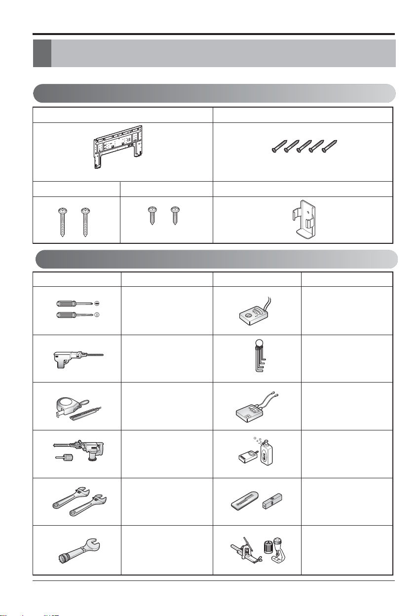
Installation Parts
Installation Tools
Installation
Read carefully, and then follow step by step.
Installation plate
The feature can be changed according to a type of model.
Type "C" screwType "B" screw
Figure FigureName
Screw driver
Electric drill
Type "A" screw
Remote control holder
Name
Multi-meter
Hexagonal wrench
Measuring tape, Knife
Hole core drill
Spanner
Torque wrench
Ammeter
Gas-leak detector
Thermometer,
Level
Flaring tool set
Page 9
Installation Manual 9
ENGLISH
Installation
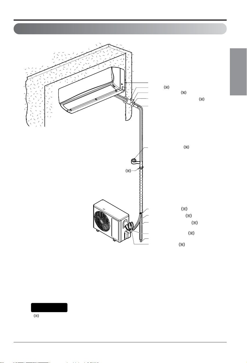
Installation Map
Connecting cable
(Optional Parts)
Vinyl tape (Wide)
• Apply after carrying out a
drainage test.
• To carry out the drainage
test, remove the air filters
and pour water into the heat
exchanger.
Saddle
Gas side piping (Optional Parts)
Liquid side piping (Optional Parts)
Additional drain pipe
Vinyl tape (Narrow)
Drain Hose
Installation plate
Sleeve
Bushing-Sleeve
Putty(Gum Type Sealant)
Bend the pipe as closely
on the wall as possible,
but be careful that it
doesn't break.
You should purchase the installation parts.
NOTICE
- The feature can be changed according a type of model.
Page 10
10 Air Conditioner
Installation
Indoor unit
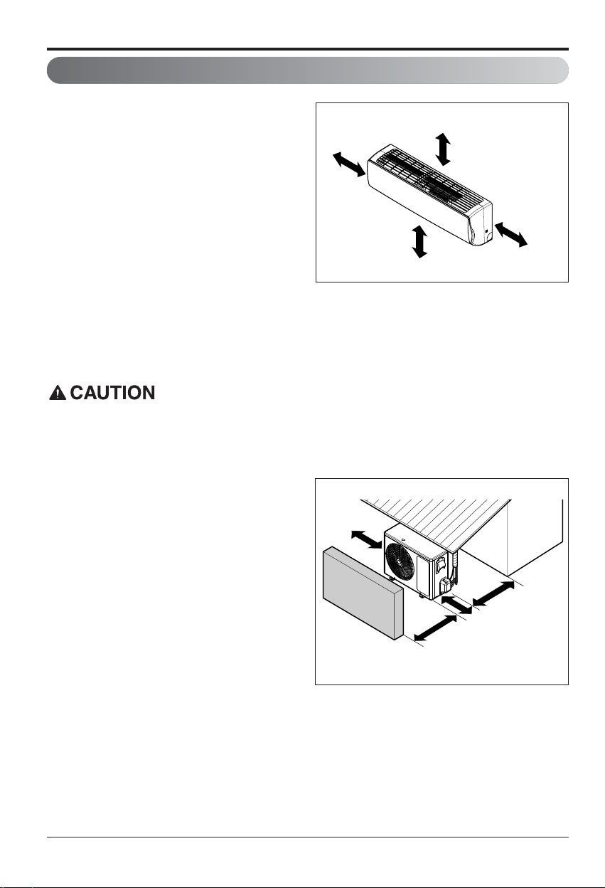
1. There should not be any heat or steam near
the unit.
2. Select a place where there are no obstacles
around of the unit.
3. Make sure that condensation drainage can
be conveniently routed away.
4. Do not install near a doorway.
5. Ensure that the interval between a wall and
the left (or right) of the unit is more than
10cm(3.9in). The unit should be installed as
high as possible on the wall, allowing a
minimum of 20cm(7.9in) from ceiling.
6. Use a metal detector to locate studs to
prevent unnecessary damage to the wall.
Select the best Location
More than
200mm(7.9in)
More than
100mm(3.9in)
More than
2400mm(8ft)
More than
100mm(3.9in)
Install the indoor unit on the wall where the height from the floor is more than 2.4m(8ft).
Outdoor unit
1. If an awning is built over the unit to prevent
direct sunlight or rain exposure, make sure
that heat radiation from the condenser is not
restricted.
2. Ensure that the space around the back and
sides is more than 30cm(11.8in). The space
in front of the unit should be more than
70cm(27.6in) of space.
3. Do not place animals and plants in the path
of the warm air.
4. Take the weight of the air conditioner into
account and select a place where noise and
vibration are minimum.
5. Select a place where the warm air and noise
from the air conditioner do not disturb
neighbors.
More than
30cm(11.8in)
More than
30cm(11.8in)
Sunroof
Fence or
obstacles
More than
70cm(27.6in)
More than
60cm(23.6in)
Page 11

Installation Manual 11
ENGLISH
Indoor unit
The wall you select should be strong and solid
enough to prevent vibration
1. Mount the installation plate on the wall with
type "A" screws. If mounting the unit on a
concrete wall, use anchor bolts.
• Mount the installation plate horizontally by
aligning the centerline using Horizontal meter
.
2. Measure the wall and mark the centerline. It is also important to use caution concerning the
location of the installation plate. Routing of the wiring to power outlets is through the walls
typically. Drilling the hole through the wall for piping connections must be done safely.
Fixing Installation Plate
Installation Plate
Chassis
Hook
Type "A" Screws
Ø70(2.76)
Ø70
(2.76)
69
(2.72)
56(2.2)
Right rear
piping
Left rear
piping
Installation Plate
Measuring Tape
Measuring Tape
Hanger
Place a level on raised tab
Unit Outline
207(8.15)
105(4.13)
[Unit : mm(inch)]
460(18.11) 570(22.44)
• Drill the piping hole with a ø70mm (2.76in)
hole core drill. Drill the piping hole at either
the right or the left with the hole slightly
slanted to the outdoor side.
Drill a Hole in the Wall
5-7mm
(3/16in~5/16in)
Indoor
WALL
Outdoor
Page 12

12 Air Conditioner
Installation
Flaring Work
Main cause for gas leakage is due to defect of flaring work. Carry out correct flaring work in the
following procedure.
Cut the pipes and the cable.
1. Use the piping kit accessory or the pipes
purchased locally.
2. Measure the distance between the indoor and
the outdoor unit.
3. Cut the pipes a little longer than measured
distance.
4. Cut the cable 1.5m(59.1in) longer than the pipe
length.
Burrs removal
1. Completely remove all burrs from the cut cross
section of pipe/tube.
2. While removing burrs put the end of the copper
tube/pipe in a downward direction while
removing burrs location is also changed in
order to avoid dropping burrs into the tubing.
Putting nut on
• Remove flare nuts attached to indoor and
outdoor unit, then put them on pipe/tube having
completed burr removal.
(not possible to put them on after finishing flare
work)
Flaring work
1. Firmly hold copper pipe in a bar with the
dimension shown in table below.
2. Carry out flaring work with the flaring tool.
Copper
pipe
90°
Slanted Uneven Rough
Pipe
Reamer
Point down
Flare nut
Copper tube
mm inch mm
Ø6.35 1/4 1.1~1.3
Ø9.52 3/8 1.5~1.7
Ø12.7 1/2 1.6~1.8
Ø15.88 5/8 1.6~1.8
Ø19.05 3/4 1.9~2.1
Outside diameter A
Bar
Copper pipe
Clamp handle
Red arrow mark
Cone
Yoke
Handle
Bar
"A"
Page 13

Installation Manual 13
ENGLISH
Installation
Check
1. Compare the flared work with the figure by.
2. If a flared section is defective, cut it off and
do flaring work again.
Indoor unit
1.
Pull the screw cap at the bottom of the indoor unit
2. Remove the chassis cover from the unit by
loosing 3 screws
3. Pull back the tubing holder.
4. Remove pipe port cover and positioning the
tubing
Inclined
Inside is shiny without scratches
Smooth all round
Even length
all round
Surface
damaged
Cracked Uneven
thickness
= Improper flaring =
Connecting the Piping
Chassis cover
Right
Indoor unit back side view
Pipe Port
Left
Tubing holder
Backwards
Page 14
14 Air Conditioner
Installation
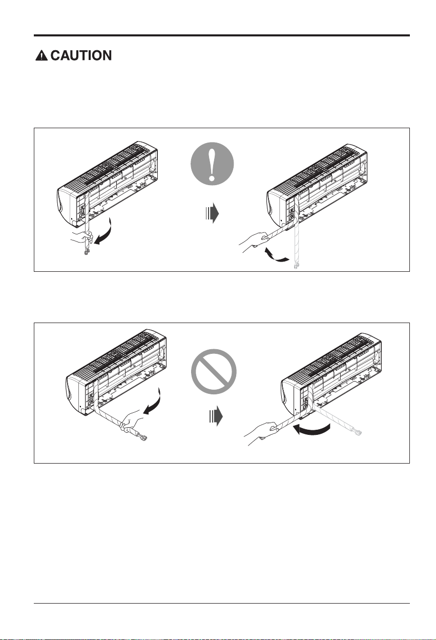
Installation Information. For right piping. Follow the instruction below.
Good case
• Press on the tubing cover and unfold the tubing to downward slowly. And then bend to the left
side slowly.
Bad case
• Following bending case from right to left directly may cause damage to the tubing.
Page 15

Installation Manual 15
ENGLISH
Installation
Installation of Indoor Unit
1. Hook the indoor unit onto the upper portion of
the installation plate.( engage the three hooks
at the top of the indoor unit with the upper edge
of the installation plate) Ensure that the hooks
are properly seated on the installation plate by
moving it left and right
2. Unlock the tubing holder from the chassis and
mount between the chassis and installation
plate in order to separate the bottom side of the
indoor unit from the wall
Installation plate
Tubing Holder
Page 16

16 Air Conditioner
Installation
If the drain hose is routed inside the room insulate the hose with an insulation material* so that
dripping from sweating (condensation) will not damage furniture or floors.
Be sure to install in the sequence of Connecting cable (Conduit), Drain hose and Connecting
pipe as the picture below describes.
* Foamed polyethylene or equivalent is recommended.
Connecting the installation pipe and
drain hose to the indoor unit.
1. Align the center of the pipes and sufficiently
tighten the flare nut by hand
2. Tighten the flare nut with a wrench
3. When needed to extend the drain hose of
indoor unit, assemble the drain pipe as
shown on the drawing
Connecting pipe
Connecting
cable(conduit)
Tape
Drain hose
Indoor unit tubing Flare nut Pipes
Wrench
Indoor unit tubing
Open-end wrench (fixed)
Connection pipe
Flare nut
Vinyl tape(narrow)
Adhesive
Drain pipe
Indoor unit drain hose
<Left side piping> <Right side piping>
Connecting pipe
Connecting
cable(conduit)
Tape
Drain hose
mm inch kgf.m lbf.ft
Ø6.35 1/4 1.8~2.5 13~18
Ø9.52 3/8 3.4~4.2 24.6~30.4
Ø12.7 1/2 5.5~6.6 39.8~47.7
Ø15.88 5/8 6.3~8.2 45.6~59.3
Outside diameter Torque
Page 17

Installation Manual 17
ENGLISH
Installation
Wrap the insulation material around the
connecting portion.
1. Overlap the connection pipe insulation
material and the indoor unit pipe insulation
material. Bind them together with vinyl tape
so that there may be no gap.
2. Wrap the area which accommodates the rear
piping housing section with vinyl tape.
3. Bundle the piping and drain hose together by
wrapping them with vinyl tape sufficient
enough to cover where they fit into the rear
piping housing section.
Finishing the indoor unit installation
1.
Mount the tubing holder in the original positon.
2.
Ensure that the hooks are properly seated on
the installation plate by moving it left and right.
3. Press the lower left and right sides of the unit
against the installation plate until the hooks
engage into their slots (clicking sound).
4.
Finish the assembly by screwing the unit to the
installation plate by using two pieces of type
"C" screws. And assemble a chassis cover.
Insulation material
Vinyl tape(narrow)
Connection pipe
Connecting cable
Vinyl tape (wide)
Wrap with vinyl tape
Indoor unit pipe
Pipe
Wrap with vinyl tape
Drain hose
Pipe
Vinyl tape(wide)
Type 'C' screw
Installation of filters
1. Pull out the triple filter and allergy free filter
from the separately packed plastic bag.
2. Insert the triple filter into the left case and
insert the allergy free filter into the right case.
3. Detach two attached tapes from the plasma
filter.
Triple Filter Plasma FilterAllergy Free Filter
Page 18

18 Air Conditioner
Installation
2. Align the center of the pipings and sufficiently
tighten the flare nut by hand.
3. Finally, tighten the flare nut with torque
wrench until the wrench clicks.
• When tightening the flare nut with torque
wrench, ensure the direction for tightening
follows the arrow on the wrench.
Liquid side piping
(Smaller diameter)
Torque wrench
Gas side piping
(Bigger diameter)
Outdoor unit
Outdoor unit
1. Remove the tubing cover from the unit by
loosening the screw.
Tubing Cover
Terminal Block
Cover control
mm inch kgf.m lbf.ft
Ø6.35 1/4 1.8~2.5 13~18
Ø9.52 3/8 3.4~4.2 24.6~30.4
Ø12.7 1/2 5.5~6.6 39.8~47.7
Ø15.88 5/8 6.3~8.2 45.6~59.3
Ø19.05 3/4 9.9~12.1 71.6~87.5
Outside diameter Torque
Page 19

Installation
Installation Manual 19
ENGLISH
Indoor
Connect the cable to the indoor unit by connecting the wires to the terminals on the control board
individually according to the outdoor unit connection. (Ensure that the color of the wires of the
outdoor unit and the terminal No. are the same as those of the indoor unit.)
Connecting the Cables
• The circuit diagram is a subject to change without notice.
• The earth wire should be longer than the common wires.
• When installing, refer to the circuit diagram on the chassis cover.
• Connect the wires firmly so that they may not be pulled out easily.
• Connect the wires according to color codes, referring to the wiring diagram.
Provide a circuit breaker between
power source and the outdoor unit as
shown below.
The power cord connected to the outdoor unit should be complied with the following
specifications (UL recognized or CSA certified).
The power connecting cable connected to the indoor and outdoor unit should be
complied with the following specifications
(UL recognized or CSA certified).
Air
Conditioner
Main power source
Circuit Breaker
Use a circuit breaker
or time delay fuse.
GN/YL
20mm
AWG_"B"
Connecting cable (208/230V)
10±
3m
m
GN/YL
20mm
Power supply cable (208/230V)
AWG_"A"
10±3m
m
18k 24k
20 25
Circuit
Breaker
(A)
Capacity(Btu/h)
18k 24k
14 12
Power
"A"
Capacity(Btu/h)
18k/24k
18
Power
"B"
Capacity(Btu/h)
When using the separate wire as the power cord, please fix the separate wire into the
control box panel by using tie wrap as the fixture.
Page 20

20 Air Conditioner
Installation
Outdoor
1. Remove the cover control from the unit by
loosening the screw.
Connect the wires to the terminals on the
control board individually as the following.
2. Secure the cable onto the control board with
the holder (clamper).
3. Refix the cover control to the original position
with the screw.
1. Separately wire power supply cord and connecting cable.
2. Use heat-proof electrical wiring capable of withstanding temperature up to 75°C(167°F).
3. Use outdoor and waterproof connection cable rated more than 300V for the connection between
indoor and outdoor unit. (For example, Type SJO-WA)
• Be sure to comply with local codes while running the wire from the indoor unit to the outdoor
unit(size of wire and wiring method, etc).
• Every wire must be connected firmly.
• No wire should be allowed to touch refrigerant tubing, the compressor or any moving parts.
NOTICE
Wiring Diagram
Outdoor unit
Terminal block
Over 5mm
(0.2")
Power supply
cord
Cover control
Conduit panel
Connecting
cable
Page 21

Installation
Installation Manual 21
ENGLISH
According to the confirmation of the above conditions, prepare the wiring as follows.
1.
Never fail to have an individual power circuit specifically for the air conditioner. As for the
method of wiring, be guided by the circuit diagram posted on the inside of control cover.
2.
The screw which fasten the wiring in the casing of electrical fittings are liable to come loose from
vibrations to which the unit is subjected during the course of transportation. Check them and
make sure that they are all tightly fastened. (If they are loose, it could cause burn-out of the wires.)
3. Specification of power source.
4. Confirm that electrical capacity is sufficient.
5. See that the starting voltage is maintained at more than 90 percent of the rated
voltage marked on the name plate.
6. Confirm that the cable thickness is as specified in the power source specification.
(Particularly note the relation between cable length and thickness.
7. Always install an earth leakage circuit breaker in a wet or moist area.
8. The following would be caused by voltage drop.
• Vibration of a magnetic switch, which will damage the contact point, fuse breaking, disturbance of
the normal function of the overload.
9.
The means for disconnection from a power supply shall be incorporated in the fixed wiring
and have an air gap contact separation of at least 3mm in each active(phase) conductors.
How to connect wiring to the terminals
◼ For strand wiring
(1) Cut the wire end with a wire cutter or wire-
cutting pliers, then strip the insulation to
expose the strand wiring about 10mm(3/8in).
(2) Using a screwdriver, remove the terminal
screw(s) on the terminal plate.
(3) Using a round terminal fastener or pliers,
securely clamp each stripped wire end with a
round terminal.
(4) Position the round terminal wire, and replace
and tighten the terminal screw using a
screwdriver.
Power supply cable
Connecting cable
Strip 10mm(3/8in)
Round
terminal
Connecting cable
Loosening the
terminal block
screw
Fastening the
wire tightly
Strand wire
Page 22

22 Air Conditioner
Installation
Checking the Drainage
To check the drainage.
1. Pour a glass of water on the evaporator.
2. Ensure the water flows through the drain
hose of the indoor unit without any leakage
and goes out the drain exit.
Drain piping
1. The drain hose should point downward for
easy drain flow.
2. Do not make drain piping like the following.
Drain Pan
Drain
Hose
Leakage
Checking
Connecting area
drain hose
Leakage
checking
Downward slope
Do not raise
Accumulated
drain water
Tip of drain hose
dipped in water
Air
Waving
Water
leakage
Water
leakage
Ditch
Less than
50mm gap
Water
leakage
Page 23

Installation Manual 23
ENGLISH
Installation
Forming the Piping
In cases where the outdoor unit is
installed below the indoor unit
perform the following.
1. Tape the piping, drain hose and connecting
cable from down to up.
2. Secure the tapped piping along the exterior
wall using saddle or equivalent.
In cases where the Outdoor unit is
installed above the Indoor unit
perform the following.
1. Tape the piping and connecting cable from
down to up.
2. Secure the taped piping along the exterior
wall. Form a trap to prevent water entering
the room.
3. Fix the piping onto the wall using saddle or
equivalent.
Trap is required to prevent water
from entering into electrical parts.
Taping
Saddle
Drain hose
Pipings
Connecting cable
(Conduit)
Seal small openings
around pipings with a
gum type sealant.
Seal a small opening
around the pipings
with gum type sealant.
Trap
Trap
Page 24

24 Air Conditioner
Installation
Air Purging
The air and moisture remaining in the refrigerant system have undesirable effects as indicated below.
1. Pressure in the system rises.
2. Operating current rises.
3. Cooling(or heating) efficiency drops.
4. Moisture in the refrigerant circuit may freeze and block capillary tubing.
5. Water may lead to corrosion of parts in the refrigeration system.
Therefore, after evacuating the system, take a leak test for the piping and tubing between the
indoor and outdoor unit.
Air purging with vacuum pump
1. Preparation
• Check that each tube(both liquid and gas side tubes) between the indoor and outdoor units have been
properly connected and all wiring for the test run has been completed. Remove the service valve caps
from both the gas and the liquid side on the outdoor unit. Note that both the liquid and the gas side
service valves on the outdoor unit are kept closed at this stage.
2. Leak test
• Connect the manifold valve(with pressure gauges) and dry nitrogen gas cylinder to this service port with
charge hoses.
Be sure to use a manifold valve for air purging. If it is not available, use a stop valve for this
purpose. The knob of the 3-way valve must always be kept close.
• Pressurize the system to not more than 150 P.S.I.G. with dry nitrogen gas and close the cylinder
valve when the gauge reading reaches 150 P.S.I.G. Next, test for leaks with liquid soap.
To avoid nitrogen entering the refrigerant system in a liquid state, the top of the cylinder must be
higher than its bottom when you pressurize the system. Usually, the cylinder is used in a vertical
standing position.
1. Do a leak test of all joints of the tubing(both indoor and outdoor) and both gas and liquid side
service valves.
Bubbles indicate a leak. Be sure to
wipe off the soap with a clean
cloth.
2. After the system is found to be free
of leaks, relieve the nitrogen
pressure by loosening the charge
hose connector at the nitrogen
cylinder. When the system
pressure is reduced to normal,
disconnect the hose from the
cylinder.
Lo Hi
Indoor unit
Outdoor unit
Manifold valve
Charge hose
Nitrogen gas
cylinder(in vertical
standing position)
Pressure
gauge
Page 25

Installation Manual 25
ENGLISH
Installation
Soap water method
1. Remove the caps from the 2-way and 3-way
valves.
2. Remove the service-port cap from the 3-way valve.
3. Apply a soap water or a liquid neutral detergent on
the indoor unit connection or outdoor unit
connections by a soft brush to check for leakage of
the connecting points of the piping.
4. If bubbles come out, the pipes have leakage
Evacuation
1. Connect the charge hose end described in the
preceding steps to the vacuum pump to
evacuate the tubing and indoor unit.
Confirm the "Lo" knob of the pressure Gauge is
open. Then, run the vacuum pump.
The operation time for evacuation varies with
tubing length and capacity of the pump. The
following table shows the time required for
evacuation.
2. When the desired vacuum is reached, close the
knob of the 3-way valve and stop the vacuum
pump.
Finishing the Job
1. With a service valve wrench, turn the valve of
liquid side counter-clockwise to fully open the
valve
2. Turn the valve of gas side counter clockwise to
fully open the valve
3. Loosen the charge hose connected to the gas
side service port slightly to release the pressure,
then remove the hose.
4. Replace the flare nut and its bonnet on the gas
side service port and fasten the flare nut
securely with an adjustable wrench. This
process is very important to prevent leakage
from the system
5. Replace the valve caps at both gas and liquid
side service valves and fasten them tight.
This completes air purging with a vacuum pump.
6. Replace the pipe cover to the outdoor unit by
one screw
Now the air conditioner is ready for test run.
Outdoor unit
Gas side
Liquid side
Cap
Hexagonal wrench
3-way valve
(Open)
3-way valve
(Close)
Required time for evacuation when 30 gal/h vacuum
pump is used
10 min. or more 15 min. or more
If tubing length is less
than 10m (33 ft)
If tubing length is longer
than 10m (33 ft)
Outdoor unit
Lo Hi
Manifold valve
Vacuum pump
Pressure
gauge
Open
Close
Indoor unit
Page 26

26 Air Conditioner
Installation
1. Check that all tubing and wiring are properly connected.
2. Check that the gas and liquid side service valves are fully open.
Prepare remote controller
1. Remove the battery cover by pulling it
according to the arrow direction.
2. Insert new batteries making sure that the (+)
and (–) of battery are installed correctly.
3. Reattach the cover by pushing it back into
position.
• Use 2 AAA(1.5volt) batteries. Do not use
rechargeable batteries.
•
Remove the batteries from the remote controller
if the system is not used for a long time.
NOTICE
Test Running
Page 27

Installation Manual 27
ENGLISH
Installation
If the actual pressure is higher than shown, the system is most likely over-charged, and charge
should be removed. If the actual pressure are lower than shown, the system is most likely
undercharged, and charge should be added.
NOTICE
PUMP DOWN
This is performed when the unit is relocated or the refrigerant circuit is serviced.
Pump Down means collecting all refrigerant into the outdoor unit without the loss of refrigerant.
Be sure to perform Pump Down procedure in the cooling mode.
Pump Down Procedure
1. Connect a low-pressure gauge manifold hose to the charge port on the gas side service valve.
2.
Open the gas side service valve halfway and purge the air in the manifold hose using the refrigerant.
3. Close the liquid side service valve(all the way).
4. Turn on the unit's operating switch and start the cooling operation.
5. When the low-pressure gauge reading becomes 1 to 0.5kg/cm
2
G(14.2 to 7.1 P.S.I.G.), fully close
the gas side valve and then quickly turn off the unit. Now Pump Down procedure is completed,
and all refrigerant is collected into the outdoor unit.
Settlement of outdoor unit
1. Fix the outdoor unit with a bolt and
nut(ø10mm) tightly and horizontally on a
concrete or rigid mount.
2.
When installing on the wall, roof or rooftop, anchor
the mounting base securely with a nail or wire
assuming the influence of wind and earthquake.
3.
If the vibration of the unit is transmitted to the
pipe, secure the unit with an anti-vibration rubber.
Evaluation of the performance
Operate the unit for 15~20 minutes, then check
the system refrigerant charge:
1. Measure the pressure of the gas side service
valve.
2. Measure the air temperature from inlet and
outlet of air conditiioner.
3. Ensure the difference between the inlet and
outlet temperature is more than 8°C(46.4°F).
4. For reference; the gas side pressure at
optimum condition is shown on table
(cooling)
The air conditioner is now ready to use.
Bolt
Tubing connection
Discharge
temperature
Discharge air
Intake temperature
R-410A 35°C (95°F) 8.5~9.5kg/cm2G(120~135 P.S.I.G.)
Outside ambient
TEMP.
Refrigerant
The pressure of the gas side
Page 28
28 Air Conditioner
Installation
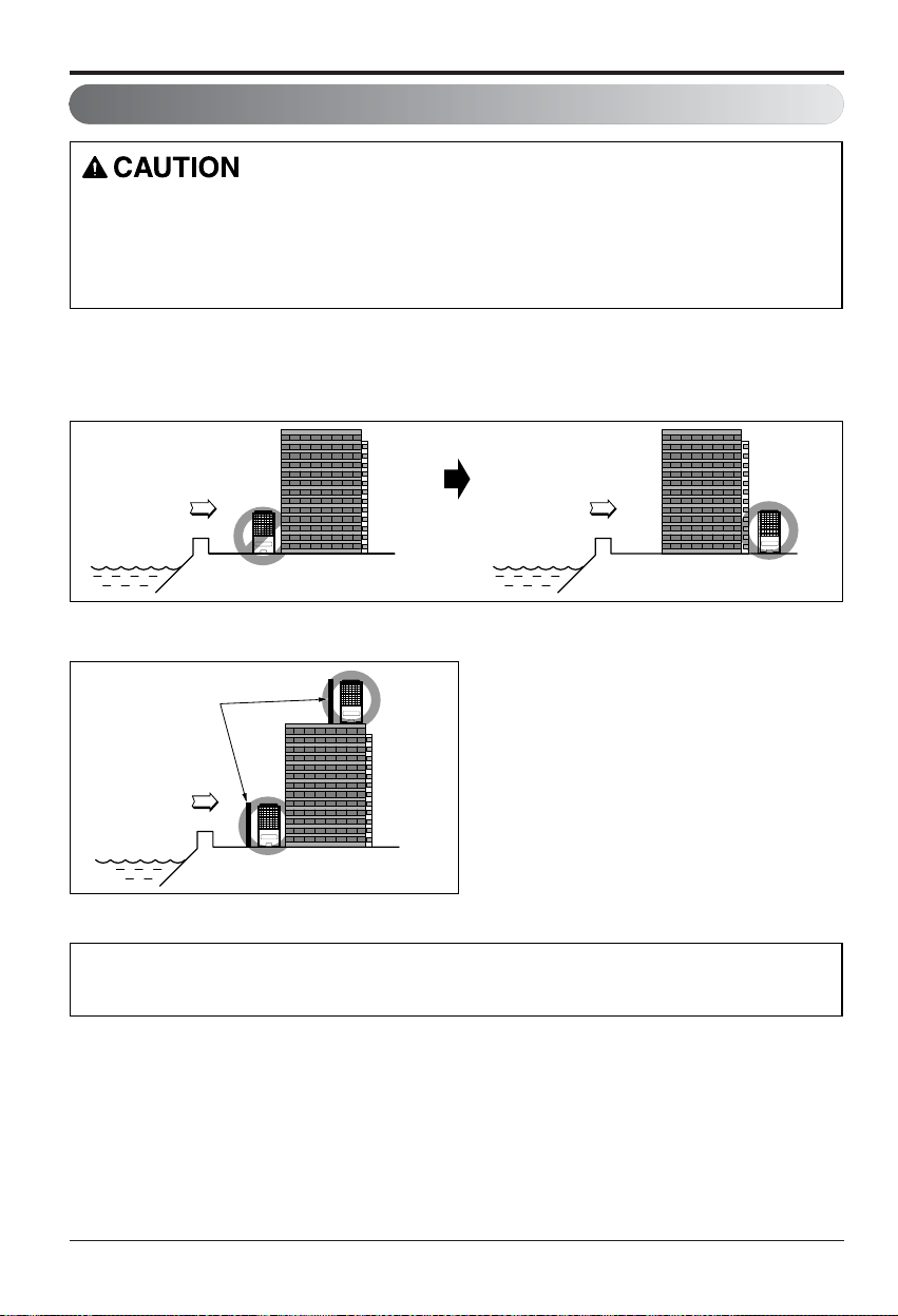
Installation guide at the seaside
1.
Air conditioners should not be installed in areas where corrosive gases, such as acid or alkaline gas, are produced.
2. Do not install the product where it could be exposed to sea wind (salty wind) directly. It can result corrosion
on the product. Corrosion, particularly on the condenser and evaporator fins, could cause product malfunction or inefficient performance.
3. If outdoor unit is installed close to the seaside, it should avoid direct exposure to the sea wind. Otherwise it
needs additional anticorrosion treatment on the heat exchanger.
1.
If you can’t meet above guide line in the seaside installation, please contact LG Electronics for the additional anticorrosion treatment.
2. Periodic ( more than once/year ) cleaning of the dust or salt particles stuck on the heat exchanger by using water
Selecting the location(Outdoor Unit)
1) If the outdoor unit is to be installed close to the seaside, then direct exposure to the sea wind should be avoided.
Install the outdoor unit on the opposite side of the sea wind direction.
2) In case of installing the outdoor unit on the sea side, setup a windbreak to prevent sea wind.
3) Select a well-drained place.
• It should be strong enough like concrete to prevent the
sea wind from the sea.
• The height and width should be more than 150%
of the outdoor unit.
• Keep more than 70 cm of space between
outdoor unit and the windbreak for easy air flow.
Sea wind
Windbreak
Sea wind Sea wind
Page 29

Installation Manual 29
ENGLISH
Installation
Piping Length and Elevation
Outdoor unit
Indoor unit
A
B
Outdoor unit
Indoor unit
A
B
18k Ø12.7 1/2 Ø6.35 1/4 7.5(25) 15(50) 30(99) 20
24k Ø15.88 5/8 Ø9.52 3/8 7.5(25) 15(50) 30(99) 35
Pipe Size
Capacity
(Btu/h)
GAS LIQUID
mm inch mm inch
Additional
Refrigerant (g/m)
Standard
Length
m (ft)
Max.
Elevation
B m(ft)
Max.
Length
A m(ft)
Capacity is based on standard length and maximum allowable length is on the basis of reliability.
Additional refrigerant must be charged after 7.5m(25ft).
Page 30

30 Air Conditioner
Page 31

After reading this manual, keep it in a place easily accessible to the user for
future reference.
LGEUS
LG Electronics, Air conditioning Division
1000 Sylvan Ave., Englewood Cliffs, NJ 07632
USA, press #2 for PTAC, TTW
USA, press #3 for DFS, Multi V
CANADA
888-865-3026
888-865-3026
1-888-LG-Canada
www.lge.com
LG Customer Information Center
Register your product Online!
LGECI
LG Electronics Canada Inc.
550 Matheson Blvd. East, Mississauga, Ontario, L4Z 4G3
 Loading...